

Page 1

INSTRUCTION MANUAL
Digital Video Recorder
with Multiplexer Function
About this manual
Before installing and using this unit, please read this manual carefully.
Be sure to keep it handy for later reference.
DSR-2004
GB
● Refer to the included CD-ROM for the German, French, Spanish and Italian “INSTRUCTION MANUAL”.
● Die “BEDIENUNGSANLEITUNG” in den Sprachen Deutsch, Französisch, Spanisch und Italienisch
finden Sie auf der beiliegenden CD-ROM.
● Utilisez le CD-ROM fourni pour consulter le “MANUEL D’INSTRUCTIONS” en allemand, français,
espagnol et italien.
● Consulte en el CD-ROM suministrado el “MANUAL DE INSTRUCCIONES” en alemán, francés, español e
italiano.
● Per il “MANUALE DI ISTRUZIONI” in Tedesco, Francese, Spagnolo e Italiano, fare riferimento al
CD-ROM allegato.
Page 2

Table of Contents
Safety precautions . . . . . . . . . . . . . . . . . . . . . . . . . . . . . . . ii
These precautions must be followed for safety reasons. . . . iii
Follow the points outlined below for proper use . . . . . . . . . viii
Main Features . . . . . . . . . . . . . . . . . . . . . . . . . . . . . . . . . . . 1
Main parts replacement timings . . . . . . . . . . . . . . . . . . . . 1
Accessories . . . . . . . . . . . . . . . . . . . . . . . . . . . . . . . . . . . . 1
Installing a hard disk . . . . . . . . . . . . . . . . . . . . . . . . . . . . . 2
Names and functions of parts. . . . . . . . . . . . . . . . . . . . . . 3
Names of each part and connections. . . . . . . . . . . . . . . . 4
Basic connections. . . . . . . . . . . . . . . . . . . . . . . . . . . . . . . . . . . 4
Network connection (ETHERNET) . . . . . . . . . . . . . . . . . . . . . . 5
Pre-operation preparation . . . . . . . . . . . . . . . . . . . . . . . . . 6
Screen display . . . . . . . . . . . . . . . . . . . . . . . . . . . . . . . . . . . . . . 6
ASetting the television system and the monitor output . . . 7
BSetting the clock (CLOCK SET) . . . . . . . . . . . . . . . . . . . . . . 7
CSetting the language (LANGUAGE). . . . . . . . . . . . . . . . . . . 9
DSetting the summer time (D.S.T./SUMMER TIME) . . . . . . . 9
Monitoring the camera videos. . . . . . . . . . . . . . . . . . . . . 10
A
Single-screen display . . . . . . . . . . . . . . . . . . . . . . . . . . . . . 10
BQuad-screen display . . . . . . . . . . . . . . . . . . . . . . . . . . . . . . 10
CCamera sequencing . . . . . . . . . . . . . . . . . . . . . . . . . . . . . . 10
Operating the PTZ camera. . . . . . . . . . . . . . . . . . . . . . . . 11
Connection. . . . . . . . . . . . . . . . . . . . . . . . . . . . . . . . . . . . . . 11
1
2Settings . . . . . . . . . . . . . . . . . . . . . . . . . . . . . . . . . . . . . . . . 11
3Operation . . . . . . . . . . . . . . . . . . . . . . . . . . . . . . . . . . . . . . . 11
Recording . . . . . . . . . . . . . . . . . . . . . . . . . . . . . . . . . . . . . 12
Real time recording. . . . . . . . . . . . . . . . . . . . . . . . . . . . . . . 12
A
BCONTINUOUS recording. . . . . . . . . . . . . . . . . . . . . . . . . . . 13
CBY MOTION recording . . . . . . . . . . . . . . . . . . . . . . . . . . . . 13
DBY EXT. SENSOR recording. . . . . . . . . . . . . . . . . . . . . . . . 14
EBY SCHEDULE recording . . . . . . . . . . . . . . . . . . . . . . . . . . 15
Playing back recorded videos. . . . . . . . . . . . . . . . . . . . . 17
EVENT SEARCH . . . . . . . . . . . . . . . . . . . . . . . . . . . . . . . . . 18
A
BTIMELINE SEARCH . . . . . . . . . . . . . . . . . . . . . . . . . . . . . . . 19
CT/D SEARCH . . . . . . . . . . . . . . . . . . . . . . . . . . . . . . . . . . . . 19
DGO FIRST . . . . . . . . . . . . . . . . . . . . . . . . . . . . . . . . . . . . . . . 19
EGO LAST . . . . . . . . . . . . . . . . . . . . . . . . . . . . . . . . . . . . . . . 20
FLOG. . . . . . . . . . . . . . . . . . . . . . . . . . . . . . . . . . . . . . . . . . . . 20
GBOOKMARK. . . . . . . . . . . . . . . . . . . . . . . . . . . . . . . . . . . . . 20
Copying the recorded videos to a USB device . . . . . . . 21
A
Marking and copying live videos. . . . . . . . . . . . . . . . . . . . 21
BMarking and copying playback videos . . . . . . . . . . . . . . . 22
Configuration and function of the Menu settings . . . . . 23
LIVE settings. . . . . . . . . . . . . . . . . . . . . . . . . . . . . . . . . . . 25
Setting the OSD and OSD CONTRAST . . . . . . . . . . . . . . . 25
A
BSetting the SEQUENCE and SEQ-DWELL TIME. . . . . . . . 25
CSetting the EVENT BEEP . . . . . . . . . . . . . . . . . . . . . . . . . . 25
DSetting a CHANNEL. . . . . . . . . . . . . . . . . . . . . . . . . . . . . . . 26
ESetting the VGA SCREEN MODE . . . . . . . . . . . . . . . . . . . . 26
FSetting an ERROR ALARM . . . . . . . . . . . . . . . . . . . . . . . . . 26
RECORD settings . . . . . . . . . . . . . . . . . . . . . . . . . . . . . . . 27
Setting the RESOLUTION . . . . . . . . . . . . . . . . . . . . . . . . . . 27
A
BSetting a CHANNEL. . . . . . . . . . . . . . . . . . . . . . . . . . . . . . . 27
CSetting the TIMER SET . . . . . . . . . . . . . . . . . . . . . . . . . . . . 28
SYSTEM settings . . . . . . . . . . . . . . . . . . . . . . . . . . . . . . . 29
A
Setting the DVR ID. . . . . . . . . . . . . . . . . . . . . . . . . . . . . . . . 29
BDESCRIPTION confirmation . . . . . . . . . . . . . . . . . . . . . . . . 29
CSetting the LOAD DEFAULT. . . . . . . . . . . . . . . . . . . . . . . . 29
DSetting an ADMIN PASSWORD . . . . . . . . . . . . . . . . . . . . . 30
ESetting a NETWORK PASSWORD . . . . . . . . . . . . . . . . . . . 31
FSetting the DATE FORMAT. . . . . . . . . . . . . . . . . . . . . . . . . 31
GSetting the CLOCK SET . . . . . . . . . . . . . . . . . . . . . . . . . . . 31
HSetting the PTZ CONTROL . . . . . . . . . . . . . . . . . . . . . . . . . 31
ISetting the LANGUAGE . . . . . . . . . . . . . . . . . . . . . . . . . . . 31
JSetting a REMOTE CONTROLLER ID . . . . . . . . . . . . . . . . 32
NETWORK settings . . . . . . . . . . . . . . . . . . . . . . . . . . . . . .33
Setting the PORT. . . . . . . . . . . . . . . . . . . . . . . . . . . . . . . . . 33
A
BSetting a CLIENT ACCESS . . . . . . . . . . . . . . . . . . . . . . . . . 33
CSetting the BANDWIDTH SAVING . . . . . . . . . . . . . . . . . . . 33
DSetting the NETWORK TYPE . . . . . . . . . . . . . . . . . . . . . . . 34
ESetting the SEND E-MAIL . . . . . . . . . . . . . . . . . . . . . . . . . . 35
HDD SET settings . . . . . . . . . . . . . . . . . . . . . . . . . . . . . . .37
A
Setting the OVERWRITE. . . . . . . . . . . . . . . . . . . . . . . . . . . 37
BFORMAT settings . . . . . . . . . . . . . . . . . . . . . . . . . . . . . . . . 37
SERVICE settings . . . . . . . . . . . . . . . . . . . . . . . . . . . . . . .38
Setting the USB UPGRADE . . . . . . . . . . . . . . . . . . . . . . . . 38
A
BSetting the SAVE SETUP TO A USB . . . . . . . . . . . . . . . . . 38
CSetting the LOAD SETUP FROM A USB . . . . . . . . . . . . . . 38
Operations using the Network . . . . . . . . . . . . . . . . . . . . .39
Connection and settings. . . . . . . . . . . . . . . . . . . . . . . . . . . . . 39
Operating environment . . . . . . . . . . . . . . . . . . . . . . . . . . . . . . 39
Installing "Sanyo DVR Utility 2004" . . . . . . . . . . . . . . . . . . . . 39
To uninstall the software. . . . . . . . . . . . . . . . . . . . . . . . . . . . . 40
Connecting to this unit . . . . . . . . . . . . . . . . . . . . . . . . . . .41
Main screen structure and function of each part . . . . . .42
Function of the operation panel. . . . . . . . . . . . . . . . . . . . . . . 43
Main screen basic operations . . . . . . . . . . . . . . . . . . . . .44
A
Switching the display mode of the screen . . . . . . . . . . . . 44
BRecording live video . . . . . . . . . . . . . . . . . . . . . . . . . . . . . . 45
CFreezing the live video . . . . . . . . . . . . . . . . . . . . . . . . . . . . 45
DThe audio is output . . . . . . . . . . . . . . . . . . . . . . . . . . . . . . . 45
ESaving images . . . . . . . . . . . . . . . . . . . . . . . . . . . . . . . . . . . 46
FOperating the PTZ camera . . . . . . . . . . . . . . . . . . . . . . . . . 46
Search mode operations. . . . . . . . . . . . . . . . . . . . . . . . . .47
Searching and playing recorded video . . . . . . . . . . . . . . . 48
A
BBacking up DVR recorded video . . . . . . . . . . . . . . . . . . . . 49
Setup menu settings . . . . . . . . . . . . . . . . . . . . . . . . . . . . .50
A
General settings (General) . . . . . . . . . . . . . . . . . . . . . . . . . 50
BCamera designation settings (Site) . . . . . . . . . . . . . . . . . . 51
CEvent settings (Event). . . . . . . . . . . . . . . . . . . . . . . . . . . . . 51
DEvent log search, view, save (Log View). . . . . . . . . . . . . . 52
ERecord settings (Record) . . . . . . . . . . . . . . . . . . . . . . . . . . 52
FDisk settings (Disk). . . . . . . . . . . . . . . . . . . . . . . . . . . . . . . 53
GVersion information (About). . . . . . . . . . . . . . . . . . . . . . . . 53
Part names of the remote control . . . . . . . . . . . . . . . . . .54
Specifications . . . . . . . . . . . . . . . . . . . . . . . . . . . . . . . . . .55
i
Page 3
Safety precautions
CAUTION
RISK OF ELECTRIC SHOCK
DO NOT OPEN
CAUTION: TO REDUCE THE RISK OF ELECTRIC
SHOCK, DO NOT REMOVE COVER (OR BACK).
NO USER-SERVICEABLE PARTS INSIDE.
REFER SERVICING TO QUALIFIED SERVICE
PERSONNEL.
WARNING: To reduce a risk of fire or electric shock, do not expose
this product to rain or moisture.
CAUTION: Changes or modifications not expressly approved by the
manufacturer may void the user’s authority to operate this equipment.
The lightning flash with arrowhead symbol, within an
equilateral triangle, is intended to alert the user to the
presence of uninsulated “dangerous voltage” within the
product’s enclosure that may be of sufficient magnitude to
constitute a risk of electric shock to persons.
The exclamation point within an equilateral triangle is
intended to alert the user to the presence of important
operating and maintenance (servicing) instructions in the
literature accompanying the product.
This equipment has been tested and found to comply with the limits
for a Class B digital device, pursuant to Part 15 of the FCC Rules.
These limits are designed to provide reasonable protection against
harmful interference in a residential installation. This equipment
generates, uses and can radiate radio frequency energy and, if not
installed and used in accordance with the instructions, may cause
harmful interference to radio communications. However, there is no
guarantee that interference will not occur in a particular installation.
If this equipment does cause harmful interference to radio or television
reception, which can be determined by turning the equipment off and
on, the user is encouraged to try to correct the interference by one or
more of the following measures.
• Reorient or relocate the receiving antenna.
• Increase the separation between the equipment and receiver.
• Connect the equipment into an outlet on a circuit different from
that to which the receiver is connected.
• Consult the dealer or an experienced radio/TV technician for help.
For the customers in Canada
This class B digital apparatus complies with Canadian ICES-003.
Declaration of Conformity
Model Number : DSR-2004
Trade Name : SANYO
Responsible party : SANYO FISHER COMPANY
Address : 21605 Plummer Street, Chatsworth, California
91311
Telephone No. : (818) 998-7322
• This device complies with Part 15 of the FCC Rules.
Operation is subject to the following two conditions:
(1) this device may not cause harmful interference,and
(2) this device must accept any interference received,
including interference that may cause undesired operation.
CAUTION
Danger of explosion if battery is incorrectly replaced.
Replace only with the same or equivalent type recommended by the
manufacturer.
Discard used batteries according to the manufacture’s instructions.
FOR CALIFORNIA, U.S.A. ONLY
This product contains a CR Coin Lithium Battery which
contains Perchlorate Material - special handling may apply.
See www.dtsc.ca/gov/hazardouswaste.perchlorate.
Licensed Under U.S. Patent No. 4,974,088
Please note:
Your SANYO product is designed and
manufactured with high quality materials and
components which can be recycled and
reused.
This symbol means that electrical and
electronic equipment, at their end-of-life,
should be disposed of separately from your
household waste.
Please dispose of this equipment at your local
community waste collection/recycling centre.
In the European Union there are separate
collection systems for used electrical and
electronic products.
Please help us to conserve the environment
we live in!
This symbol mark and recycle system
are applied only to EU countries and
not applied to the countries in the
other area of the world.
ii
Page 4
Safety precautions
These precautions must be followed for safety reasons.
Warning
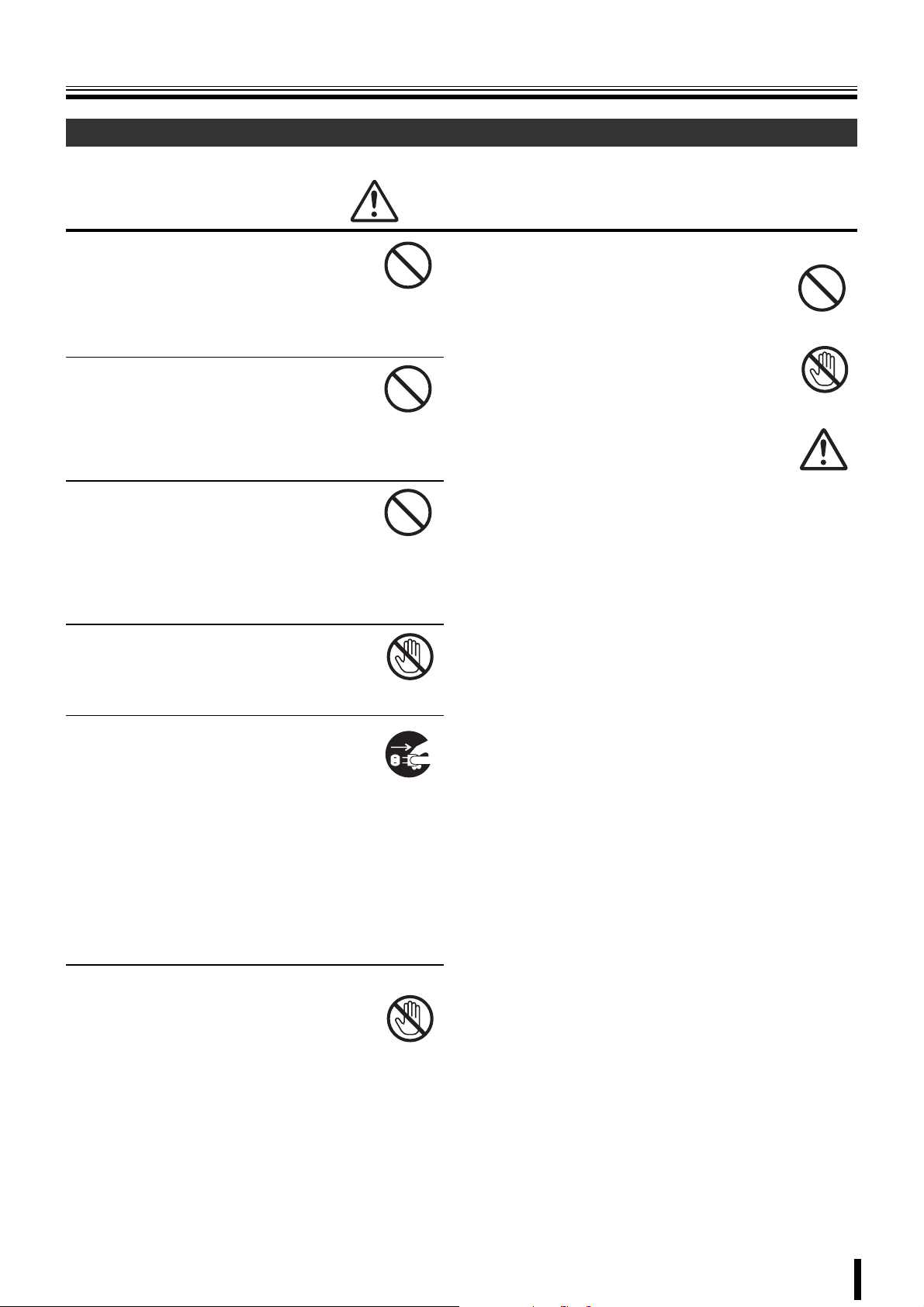
b Do not use if the unit emits smoke,
strange sounds are heard or odor is
emitted.
Continued use may cause electrocution and/
or fire. Immediately remove the power plug
Remove the power
plug from the outlet.
from the outlet. Once the unit stops emitting
smoke, consult the dealership where this unit
was purchased or factory shop for repairs.
Do not attempt repairs on your own.
b Make sure the power cable is not damaged.
• Always use the power cable supplied with
the unit.
• Do not place heavy objects on the power
cable or place the power cable near
Prohibited
heating equipment. Also, do not bend the
power cable forcefully, work upon or staple
it.
A damaged power cable may result in fire
and/or electrocution.
• Should the power cable become damaged
it must be replaced by the dealership
where this unit was purchased or factory
shop.
b Make sure there is no dust accumulation on the
power plug or the outlet.
• Dust accumulation may result in a
short-circuit and heat generation and
cause fire.
• Be especially careful when using an outlet
Prohibited
situated in a room exposed to high
humidity, condensation and/or dust, or in a
kitchen.
• Periodically remove the power plug from
the outlet and clean any dust and dirt
between the plug and the outlet.
b Caution when connecting the power cable
• Connect the power plug directly with the
outlet. Faulty connection may result in
heat generation and cause fire.
• Do not use the power cable while it is tied
in a bundle. This may result in heat
generation and cause fire.
• When using the extension cord supplied,
make sure the power consumption of the
connected unit does not exceed the
electrical rating of the extension cord.
Higher power consumption may result in
heat generation and cause fire.
Prohibited
b Disassembly prohibited
• Do not place your hand inside this unit as
this may cause fire and/or electrocution.
• Consult the dealership where this unit was
Disassembly
prohibited.
purchased or factory shop for diagnostics,
adjustments, and repairs.
b Do not place any foreign objects inside the unit.
• Do not insert or push in any metal or
combustible objects through openings
such as air ducts. This may cause fire and/
or electrocution.
Prohibited
• In the event that a foreign object is inside
the unit, turn off and unplug the unit.
Consult the dealership where this unit was
purchased or factory shop. Continued use
may result in fire and/or electrocution.
Remove the power
plug from the outlet.
b Do not place a container holding
water or other liquids above the unit
when it is connected to power.
In the event that water gets inside the unit,
turn off and unplug the unit. Consult the
dealership where this unit was purchased or
factory shop.
Continued use may result in a fire or
electrocution.
Water is prohibited
Remove the power
plug from the outlet.
b Do not allow the unit to get wet.
• This unit is not waterproof. Do not expose
the unit to water. This may cause fire and/
or electrocution.
Do not use in a bath or shower room.
• In the event that the internal components
have been exposed to water, turn the
power off and remove the power plug from
the outlet. Consult the dealership where
this unit was purchased or factory shop.
Continued use may cause electrocution
and/or fire.
Water is prohibited
Exposing to water
is prohibited
iii
Page 5
Safety precautions
Warning
b Do not use during thunder/thunder storms.
Do not use during thunder/thunder storms.
Never touch the connection cable during
thunder/thunder storms. This may cause
electrocution.
b Do not place in an unstable position.
• Doing so may cause accidents and/or
breakdowns through falling or toppling.
• In the event that the unit has been
dropped or the casing has been damaged,
turn the power off and remove the power
plug from the outlet. Consult the
dealership where this unit was purchased
or factory shop.
Continued use may cause electrocution
and fire.
b Do not expose to shock or vibration.
Stored data may be damaged or lost through
hard-disk breakdowns caused by shock/
vibration.
b Do not use this unit in areas where it is exposed
to the possibility of explosion.
Do not use this unit in areas where explosive
and/or flammable gases are present. This
may cause fire and/or explosion.
Contact prohibited
Prohibited
Remove the power
plug from the outlet.
Prohibited
Prohibited
Caution
b Do not pull on the power cable when removing
the power plug from the outlet.
Hold the power plug when disconnecting the
power cable from the outlet. Pulling on the
power cable may damage the cord. This may
cause fire and/or electrocution.
b Do not touch the power plug with wet
hands.
Doing so may result in electrocution.
b Do not sit on.
Doing so may cause the unit to fall, be
damaged and/or result in injury.
b Make sure the cables are connected properly.
Connect and install the power cable and
connection cable very carefully. Tripping over
the cable may result in the unit capsizing or
falling and cause injury.
b Do not place heavy objects on connected units.
Doing so may affect the stability of the unit
and cause it to fall which may result in injury.
Doing so may also damage the unit
depending on the weight of the object.
b Shipment and portability
• Never move this unit while the power is
turned on.
• When shipping, remove the power plug
from the outlet, confirm that the
connection cable has been removed, and
store in original packaging. Ship using a
method that causes the least amount of
shock and/or damage to this unit. Also, do
not drop this unit.
Prohibited
Wet hands
prohibited
Prohibited
Prohibited
Remove the power
plug from the outlet.
b Maintenance when the unit is going to remain
unused for long periods of time
Remove the power plug from the outlet.
Carrying out maintenance without removing
the power plug may cause electrocution.
Remove the power
plug from the outlet.
iv
Page 6
Safety precautions
Caution
b Cleaning the internal components
Consult the dealership where this unit was
purchased or factory shop for cleaning
internal components. Leaving the unit unused
for long periods of time may attract dust to the
internal components, which in turn may
cause fire and/or breakdowns.
b Do not block the cooling fans or air ducts.
• This unit is equipped with air ducts and
cooling fans in order to assist the
ventilation of hot air produced by the hard
disk drive.
Placing covers, placing in a case, or
placing inside bookcases may cause heat
build up, and may result in fire and/or
electrocution.
When the unit is set up in a rack, leave open space on all
sides.
• Leave 1 cm or more of space above and below.
• Leave 5 cm or more of space on both sides and on the
rear.
b Do not expose to extreme temperatures or
humidity changes.
• Do not place in areas where the unit will
be exposed to extreme temperatures (±10
degrees C per hour) or humidity changes.
Prohibited
Prohibited
b Cautionary points on condensation
Droplets may form on the outside when very cold water is
poured into a cup. In the same way, droplets may form
around the internal components of this unit. This is called
condensation.
Do not use this unit if condensation has formed.
Using this unit while condensation is formed may cause
breakdowns. In the event of sudden sharp temperature
changes, turn off the power and do not use this unit until
the temperature of the room where it is positioned
stabilizes (about 2 hours).
Condensation will not occur while the power is turned on.
When condensation is likely to occur ...
Use the unit after turning the power off and leaving it for
1~2 hours.
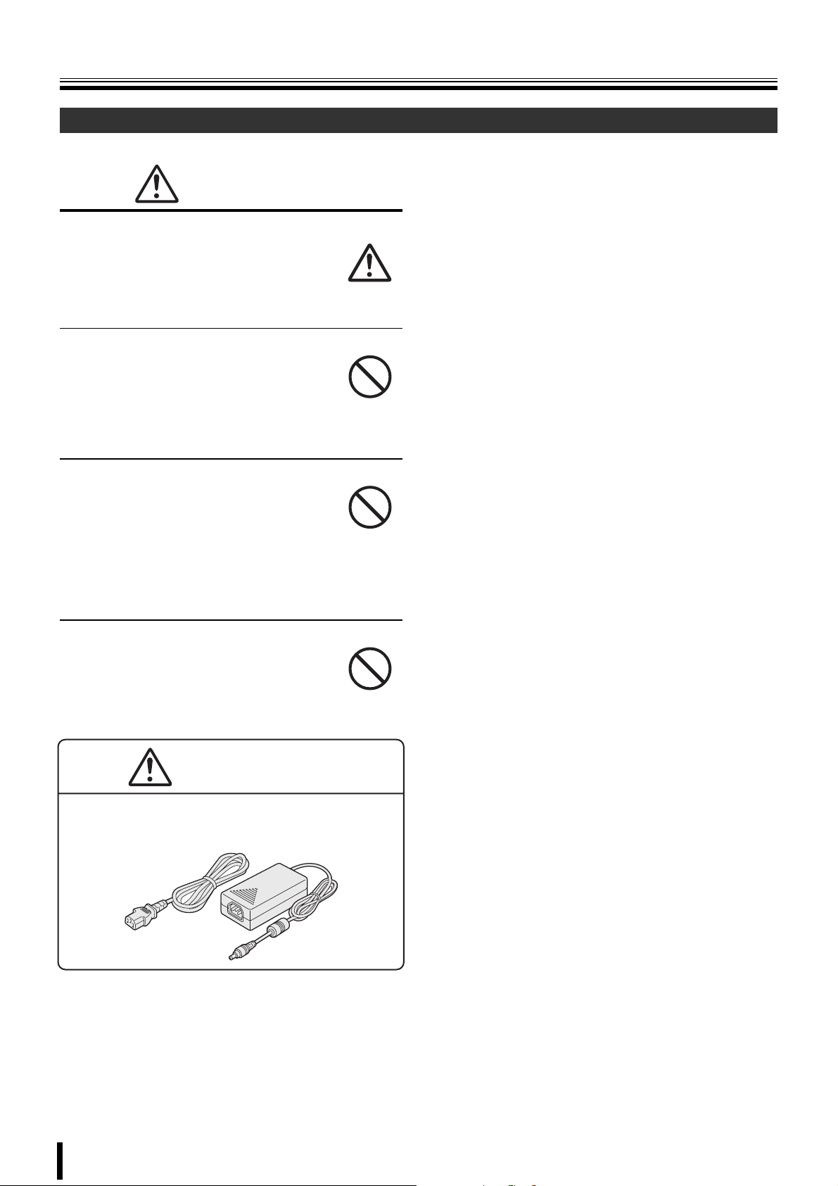
Supplied AC Adapter
Danger
b Never disassemble or modify.
• Touching the internal parts is dangerous,
and can cause fire and electrocution.
• Never use as a DC power source unit.
Disassembly
prohibited.
b Points on unit positioning
This unit is constructed using precision
electronic parts. Avoid placing it in areas
described below as this may cause faulty
operation and/or breakdowns.
• In direct sunlight
• In places exposed to water
• In the vicinity of cooling and heating units or humidifiers
• Near the air conditioner where the unit is exposed to
cool air
• Dusty areas
• Areas that contain fire hazards
• Areas that contain magnetic items
• In the vicinity of volatile substances
• Areas where the unit will be exposed to constant
vibration (in trains, cars, etc.)
Prohibited
b Never get the unit wet.
• Never submerge the unit in water or get it
wet. Doing so can cause fire and
electrocution.
• Do not use in a bath or shower room.
• In the event that water gets inside the unit,
unplug the power plug from the outlet, and
consult the dealership where this unit was
purchased. Continued use can cause fire,
electrocution, and unit breakdowns.
Water is prohibited
Exposing to water
is prohibited
v
Page 7
Safety precautions
Supplied AC Adapter
Warning
b Use only the supplied AC adapter.
Use the supplied AC adapter. Using a
different AC adapter can cause fire or
electrocution, due to differences in current
carrying capacity of the power cord.
b Do not connect to other appliances.
The AC adapter supplied is to be used with
this unit only. Connecting it with other
appliances may result in fire and/or
electrocution.
b Do not connect this unit with the AC
adapter in areas reachable to children
or where pets move freely.
Children or pets may mistakenly wrap the
adapter cable around their neck and
suffocate.
b Never touch the AC adapter with wet
hands.
Doing so can cause electrocution.
b If the unit emits smoke, strange
sounds or smells immediately remove
the AC adapter from the outlet.
• Continued use may result in fire and/or
electrocution.
• In the event that the unit does not function
correctly, immediately remove the AC
adapter from the outlet. Once the unit
stops emitting smoke, consult the
dealership where this unit was purchased.
Do not attempt to repair the unit. Doing so
may be dangerous.
Prohibited
Prohibited
Prohibited
Wet hands
prohibited
Remove the power
plug from the outlet.
b Precaution on AC adapter and plug
• Do not connect the AC adapter to a
loose outlet.
• Make sure the AC adapter is properly
plugged to the outlet.
• Do not use if the plug of the AC adapter
is damaged.
Continued use when insecurely plugged
may result in heat generation and cause
fire and/or electrocution.
• When removing the AC adapter plug
from the outlet do not pull forcefully.
Doing so may damage the plug and/or the
cable and cause fire and/or electrocution.
• Do not remove the DC plug from the DC input
terminal of the unit while the AC adapter is inserted
in the outlet.
Do not touch the plug with wet hands and/or put the
plug in your mouth. Doing so may result in
electrocution.
• Make sure there is no dust accumulation on the AC
adapter and the outlet contact area.
Dust accumulation may result in a short circuit and/or
heat generation and cause fire and/or electrocution.
Be especially careful when using an outlet situated in a
room exposed to high humidity, condensation and/or
dust, or in a kitchen.
Wiping away dust:
Remove the AC adapter from the outlet and wipe away
any dust on the metal parts using a dry cloth.
• When using an extension cord with an outlet, make
sure the power consumption of the connected unit
does not exceed the electrical rating of the
extension cord.
Higher power consumption may result in heat
generation and cause fire.
Prohibited
Wet hands
prohibited
b Do not use during thunder/thunder storms.
Do not touch the AC adapter during thunder/
thunder storms. Doing so may result in
electrocution.
Contact prohibited
vi
Page 8
Safety precautions
Supplied AC Adapter
Caution
b Make sure the cable is connected properly.
Make sure the AC adapter cable and the
connecting cables are connected properly.
Tripping over the cable may result in the unit
capsizing or falling and cause injury.
b Preventing damage to a cable
Do not place heavy objects on the AC
adapter cable or place the adapter cable near
heating equipment.
Also, do not bend the power cable forcefully,
work upon or staple it.
Prohibited
b Do not place the unit in an unstable position
• Doing so may result in the unit toppling or
falling and cause injuries and/or damages.
• In the event that the unit has fallen or the
casing has been damaged, consult the
dealership where this unit was purchased.
Continued use may result in fire,
electrocution and/or breakdown.
b Precaution on unit positioning
Do not use this unit where it is exposed to
heat (in front of a stove) or direct sunlight.
Prohibited
Prohibited
Warning
The supplied power cable/ AC Adapter is for exclusive use
with this unit. Do not use with other appliances.
vii
Page 9

Safety precautions
Follow the points outlined below for proper use
bBack up battery.
• A built-in lithium battery allows the date to be set. The
lithium battery is not rechargeable.
The life expectancy of the lithium battery is
approximately 2 years.
• When the battery is flat the monitor displays the "THE
CLOCK IS NOT RESPONDING" message. The clock is
automatically reset in case of battery fluid leak or when
the battery has reached the end of its life expectancy.
Consult the dealership where this unit was purchased
or the nearest repair center for battery replacement.
Battery fluid leaks
In the event that the battery fluid has leaked rinse hands/
clothes thoroughly with water.
Loss of eyesight may result if battery fluid enters the eyes.
Do not rub the eyes. Immediately rinse with clean water
and consult a physician.
When disposing of this unit
Consult the dealership where this unit was purchased for
information concerning the disposal of the lithium battery.
bIf unused for a lengthy period of time
Remove the power plug from the outlet. Remember to
occasionally turn the power on in order to maintain correct
function.
bPre-confirm important recording
assignments
Recording and/or playback functions may be unavailable
due to hard-drive or connecting unit failures. Always
confirm that recording can be carried out successfully
before carrying out important recording assignments. The
recorded content cannot be guaranteed.
It is recommended to periodically back up or mirror data in
order to prevent the loss of data in the event of
breakdowns, recording faults or accidents.
bMaintaining this unit
Turn the power off and remove the power plug from
the outlet. Wipe away any dust using a soft cloth.
When the stains are hard to remove...
Soak a cloth in water with diluted neutral detergent
and wring it. Wipe the stain with the moistened cloth
and finally dry off with a dry cloth.
CAUTION:
• Do not use paint thinner, benzine, or any other alcohol
based agents for cleaning. The exterior may deteriorate
or the paint may wear off.
• Follow the instructions supplied on the packaging of the
chemical cleaning agent.
• Do not spray volatile substances, such as insecticides,
etc. onto the unit. Also, avoid extended contact with
rubber or vinyl products.
This may cause exterior damage or wear the paint off.
bCopyright information
• This manual and software are copyrighted to SANYO
Electric Co., Ltd.
• Brand and product names used in this manual are the
trademarks or registered trademarks of their respective
companies.
Except for personal use, copyright law prohibits the use of
recorded copyrighted images without the permission of the
copyright holder.
bPersonal data protection
Images or footage recorded by the camera video system in
which people are captured and can be identified are
considered to be personal information and fall within the
scope of the Personal Data Protection Law. It is the
responsibility of the user to operate the system in
accordance with the above law.
viii
Page 10
Main Features
Accessories
• Real time monitoring at 200 IPS (PAL) / 240 IPS
(NTSC)
• Maximum recording speed at 100 IPS (PAL) / 120
IPS (NTSC)
• 4ch audio recording
• Remote surveillance and operation via network
• VGA video output
• Comes with IR remote control unit and DVR
utility software
Main parts
replacement timings
Continued use of this unit in a 25°C environment may result in
wear and deterioration of the parts of the unit. We
recommend you replace the following parts according to the
timings listed below. The replacement timings listed are
approximate and do not guarantee the performance of the
part in question.
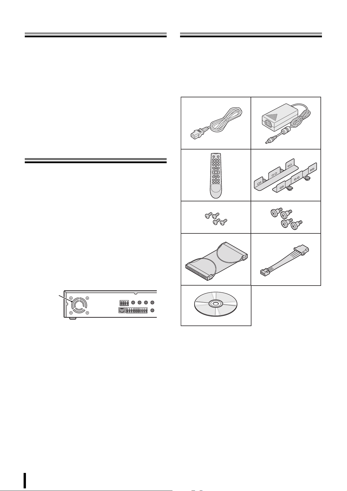
Check that all the parts shown below are supplied.
1 Power cable (×2)
2 AC adapter 3 Remote control
4 HDD mounting bracket 5 HDD bracket screw
6 HDD fixing screw 7 IDE cable
8 HDD power cable 9 CD-ROM
• Instruction Manual (Digital Video Recorder)
12
34
56
b Hard disk: 2 years (25°C environment)
The life expectancy of each part depends on the
environment in which the unit is used. However, the head
and motor are particularly prone to wear and deterioration.
Therefore, writing errors are more likely to occur after two
years of use.
b Cooling fan: 3 years (25°C environment)
Cooling fan failure causes higher internal temperatures
which may result in a faulty hard disk. Periodically check
whether the cooling fan is working properly.
Cooling
fan
b Battery: 2 years (25°C environment)
7
9
8
1
Page 11
Installing a hard disk
No default hard disk is installed at the time of purchase. To purchase and install a hard disk, consult the dealership
where this unit was purchased.
Make sure the unit is turned off before installing the hard disk.
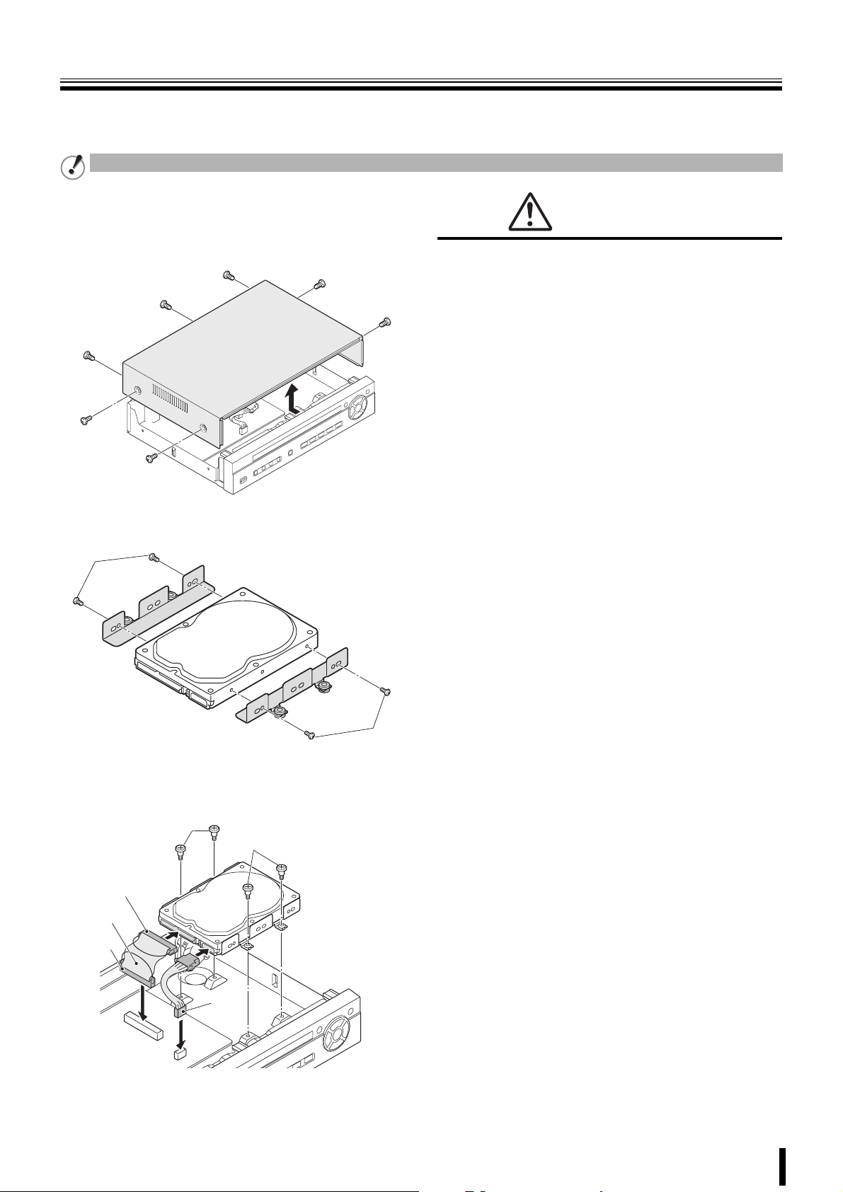
Unfasten the cover of the unit.
1
Set the mode of the hard disk to be installed to
"Master". For more information, read the hard disk
installation manual.
The hard disk is a precision instrument. To avoid damage,
handle the hard disk with care and do not expose it to shock.
Do not block the ventilation holes and do not allow the cooling
fan to stop. Doing so may cause heat build up and may
shorten the life expectancy of the hard disk.
G This unit is designed to be positioned horizontally. Do
not position vertically.
G Do not expose to shock or vibration and do not
transport while power is turned on.
Always turn the power off when moving in and out of racks
or other shelves.
G Do not remove the power plug while recording or
playing images back.
Warning
Fix the brackets to the hard disk using the supplied
2
HDD mounting bracket screws (A).
A
Connect the supplied IDE cable (B) and HDD power
3
cable (C) to the hard disk and fix the hard disk to
the unit using the supplied HDD fixing screws (D).
D
D
Black
B
Blue
C
G Do not move the unit for approximately 30 seconds
after turning the power off.
The hard disk continues to rotate for a short duration after
the power has been turned off. The unit is further
susceptible to damage through shock and vibration during
that period. It is imperative that you do not move the unit
during that time.
G Do not expose to shock or vibration.
Avoid placing this unit directly on the floor. Make sure that
the four stands attached to the base of this unit are used
when placing it on the floor.
G Always use the original packaging (packaging
A
supplied at the time of purchase), when shipping the
unit.
Make sure you use the packaging materials supplied at the
time of the original purchase when shipping the unit or a
single internal component of the unit. Select a shipping
method that will cause the least amount of shock to the
unit during shipping.
Consult the dealership where this unit was
purchased for hard disk replacement.
• The hard disk is vulnerable to static electric shocks. Take
appropriate measures to prevent exposure to static
electricity.
• Unpackaged drives should be placed horizontally with their
base plate facing upwards on top of a soft cloth. Exposing
the hard disk to shocks and vibration may cause
breakdowns.
• Do not expose the drive to shocks and/or vibrations when
removing/tightening the screws at the time of hard disk
replacement. Firmly tighten the screws after replacement.
2
Page 12
Names and functions of parts
89FGHIJKL
B
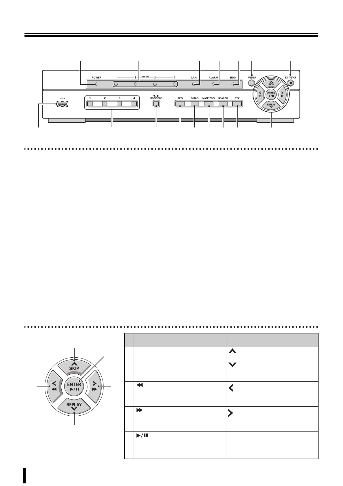
Front panel
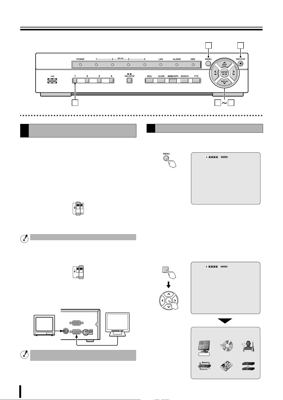
1
There is no power switch on this unit.
1 Power indicator (POWER)
The power indicator blinks when the supplied AC adapter
is connected.
2 Recording indicator (CH 1/CH 2/CH 3/CH 4)
The indicator blinks when a channel is recording.
3 LAN indicator (LAN)
The indicator blinks when the unit is connected and used
through the LAN cable.
4 Alarm indicator (ALARM)
The indicator blinks when an alarm recording occurs.
234567
9 Camera selection 1 - 4 buttons (P7)
The video of each live is displayed on single-screen.
F Record/Stop button (REC/STOP) (P12)
Starts/Stops the recording of the monitored live image
displayed.
G Automatic camera scrolling button (SEQ) (P10)
Automatically switches through and displays the images of
each live.
H Quad-screen display button (QUAD) (P10)
Displays a quad-screen.
5 Hard disk drive indicator (HDD)
The indicator blinks when the hard disk is being accessed.
6 Menu button (MENU) (P7/24)
Displays the settings menu screen and switches to setting
mode.
7 Exit/Stop button (EXIT/STOP) (P13)
During settings: Returns to the previous screen.
During playback: Interrupts playback operation.
8 USB terminal (USB) (Exclusively for 2.0) (P21)
Connect the USB memory. Video can be saved.
L Control button
C
A
E
D
Skip button (SKIP):
A
The player jumps one minute forward. :Moves the cursor upward.
Replay button (REPLAY):
The player jumps one minute
B
backward.
button:
The player fast rewinds.
C
button:
The player fast-forwards.
D
The player displays a still image.
E
Plays the image selected during the
image search operation.
I Mark/Copy button (MARK/COPY) (P21)
Switches to image saving mode.
J Search button (SEARCH) (P18)
Switches to recorded-images searching mode.
K Pan/Tilt/Zoom button (PTZ) (P11)
Switches the dome camera connected to the RS 422/485
terminal to Pan/Tilt/Zoom/Focus mode.
Playback in progress
button:
Setting in progress
(Cursor operation)
:
Moves the cursor downward.
:
Changes the settings value or moves
the cursor to the left.
:
Changes the settings value or moves
the cursor to the right.
ENTER :
Sets the selected item or displays the
settings screen.
3
Page 13
Names of each part and connections
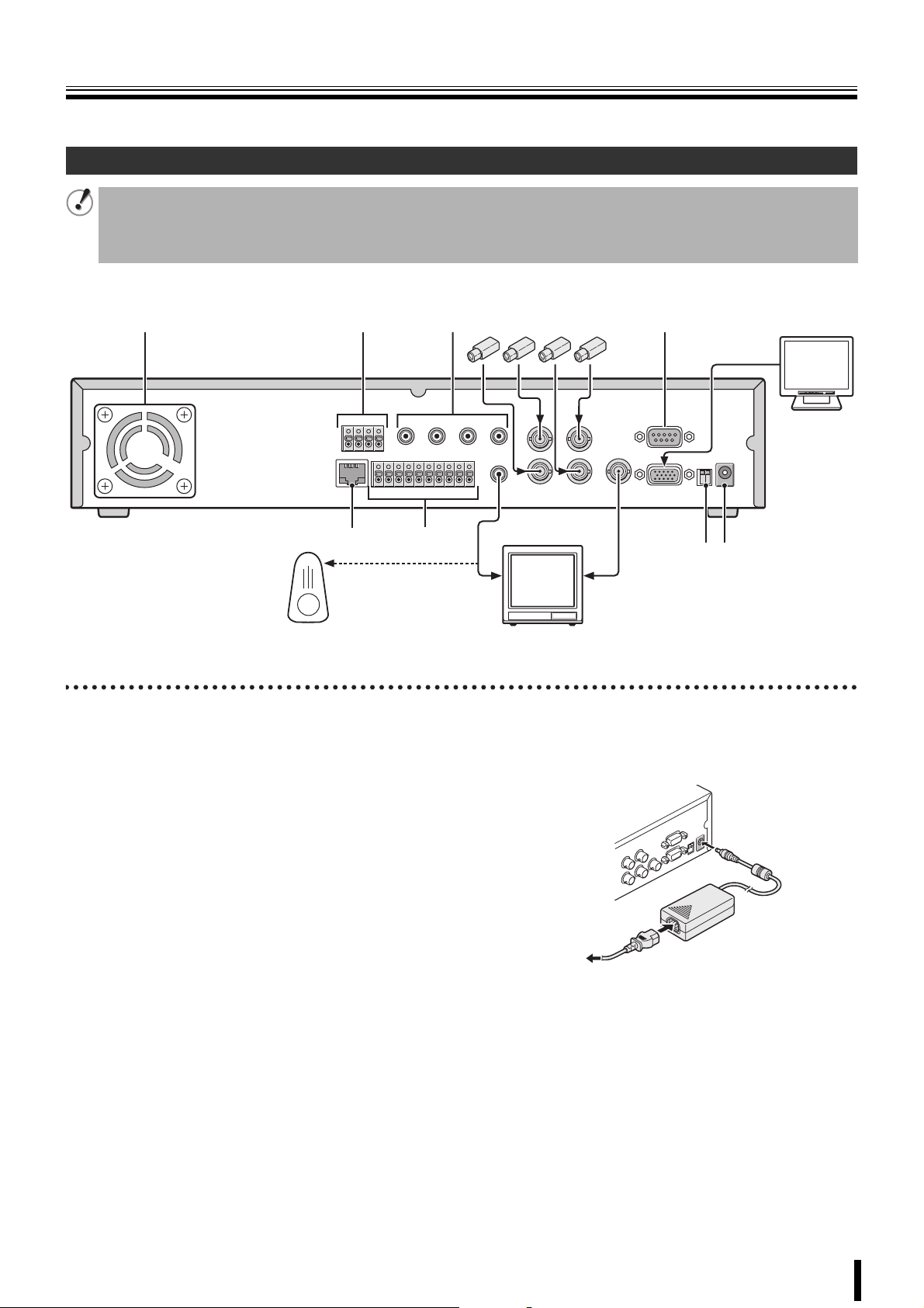
Rear panel
Basic connections
• Do not turn this unit on before all the connections are complete. Read the instruction manual of each unit carefully.
• Make sure each unit is connected properly as faulty connection may result in the unit emitting smoke and/or being damaged.
• Feed additional units with the same power source. Stored data may be lost.
• The DC plug of the AC adapter is very easily unplugged. When shifting this unit, remove the plug carefully.
1235F
Speaker with
built-in amplifier
(Sold separately)
1 Cooling fan (P1)
2 PTZ camera control terminal (RS-422/485: P11)
3 Audio input (AUDIO IN: CH1 - CH4)
4 Video input terminal (VIDEO IN: CH1 - CH4)
Camera
(Sold separately)
4
768
Video monitor
(Sold separately)
H DC12V input terminal (DC 12V)
Connect the power cable to the unit as shown in the
illustration and insert the power plug into the outlet. The
POWER indicator situated on the front panel blinks.
9
Monitor
(Sold separately)
POWERMODEAUTOMENU
H
G
To video input terminalTo audio input terminal
5 RS 232 terminal (RS-232C)
For maintenance purposes.
6 Network terminal (ETHERNET: P5)
7 External sensor terminal (SENSOR/ALARM OUT: P14)
8 Audio output terminal (AUDIO OUT)
9 Video output terminal (VIDEO OUT)
F VGA (Video Graphics Array) output terminal
Connects to the PC VGA monitor.
G System changeover switch (PAL/VGA: P7)
to AC
4
Page 14
Names of each part and connections
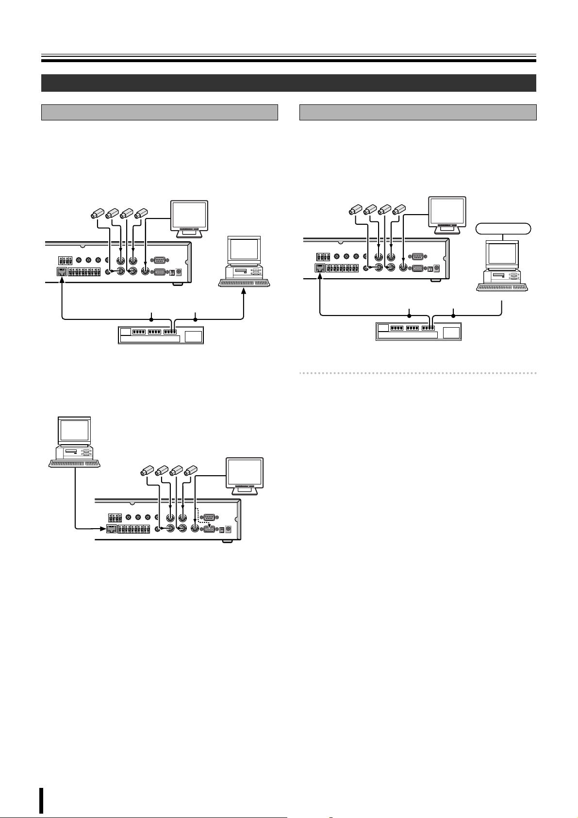
Network connection (ETHERNET)
LAN connection
b Using the switching hub
Use a 10BASE-T/100BASE-TX CAT 5 LAN cable.
When controlling the network, connect to hubs such as the
switching hub using an Ethernet cable.
Camera
(Sold separately)
Ethernet cable
(Straight cable)
Switching hub
b Without using a switching hub
Monitor
(Sold separately)
POWERMODEAUTOMENU
Computer
Internet (DHCP, ADSL) connection
Connect to the Internet using a router and the like.
When connecting to an ADSL modem or other device, read
the instruction manual of the device for information on how to
connect.
Monitor
Camera
(Sold separately)
Router or ADSL modem and the like
Memo: The type of network must be set on the NETWORK
screen. (P33)
(Sold separately)
Ethernet cable
(Straight cable)
POWERMODEAUTOMENU
Internet
Computer
Computer
Cross type
Camera
(Sold separately)
Monitor
(Sold separately)
POWERMODEAUTOMENU
5
Page 15
Pre-operation preparation
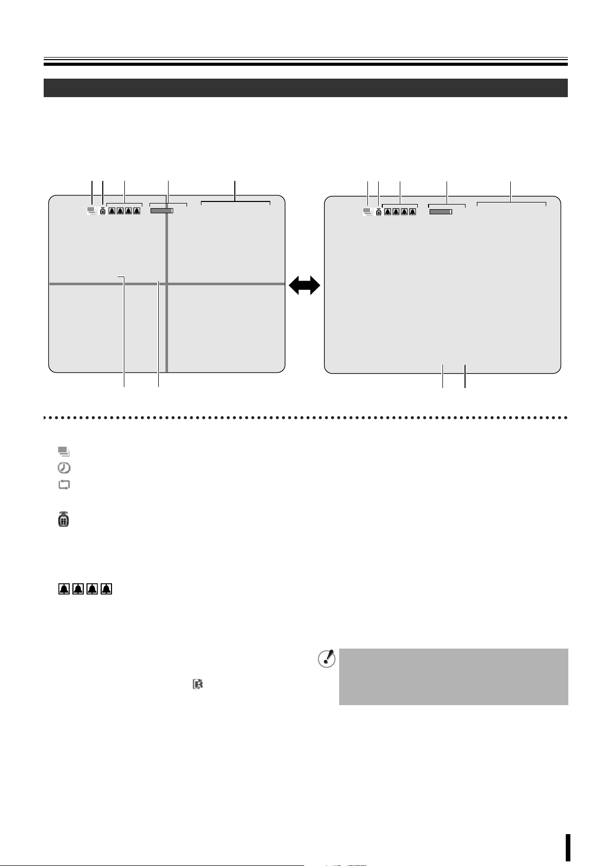
Screen display
After turning on the power, the message "INITIALIZING" is displayed. Next, the live videos are displayed on a quad-screen. The
screen display necessary to operations is displayed on the screen.
• The screen display can be hidden except for the recording screen display. (P25)
b Quad-screen b Single-screen
1 2 53 4
2%
2006/07/14 09:04:54
CH1 C
CH3
6 7
1 Operation display
: Displayed during live video sequencing.
: Displayed during alarm output.
: Displayed during remote operation by PC.
2 Remote control display (P32)
: This icon shows that remote operations are possible.
Depending on the remote ID number settings, this
icon may not be displayed and remote operations
may not be available.
3 Alarm input display
:
Blinks during motion or sensor alarm input. The mark is
one channel from the left.
4 Hard disk used capacity display
Displays the amount of recording on the hard disk from
0-99%. When the disk is full, "99%" changes to "FULL".
When the recording settings are set to overwrite and the
hard disk is full, 99% changes to which represents
overwriting mode.
CH2
CH4
1 2 53 4
2%
2006/07/14 09:04:54
CH1
C
6 7
5 Date and time display
This unit manages the recorded videos according to their
date and time. Make sure the correct date and time are set
in the menu setting. (P7)
6 Camera channel display
CH1/CH2/CH3/CH4
7 Recording display
Factory default settings start continuous recordings (C)
automatically once the power is turned on. Change the
recording mode using the menu settings. (P27)
C: Recording in the continuous mode (CONTINUOUS)
R: Recording in the real time mode (When pressing the
REC/STOP button)
M: Recording in the motion detection mode (BY EXT.
MOTION)
S: Recording in the sensor detection mode (BY SENSOR)
• If a live video is disconnected, the message "VIDEO
LOSS" is displayed on the monitor.
• If a video signal is not connected to the video input
terminal, the message "NO VIDEO" is displayed on
the monitor.
6
Page 16
Pre-operation preparation
1 8
2 3
Setting the television system and the monitor
A
output
If the television system of the camera to be connected and
the type of monitor differ, live videos cannot be monitored on
the normal screen. Check the specifications of the equipment
to be connected and set the system changeover switch on the
rear panel.
• Do not forget to turn off the power when adjusting the
settings.
b Matching the television system of the camera (PAL)
P
V
A
G
L
A
12
ON
Up: When using a NTSC camera
Down: When using a PAL camera
Cannot be used when PAL and NTSC system are mixed.
b Selecting the type of monitor (VGA)
P
V
A
G
L
A
7
Setting the clock (CLOCK SET)
B
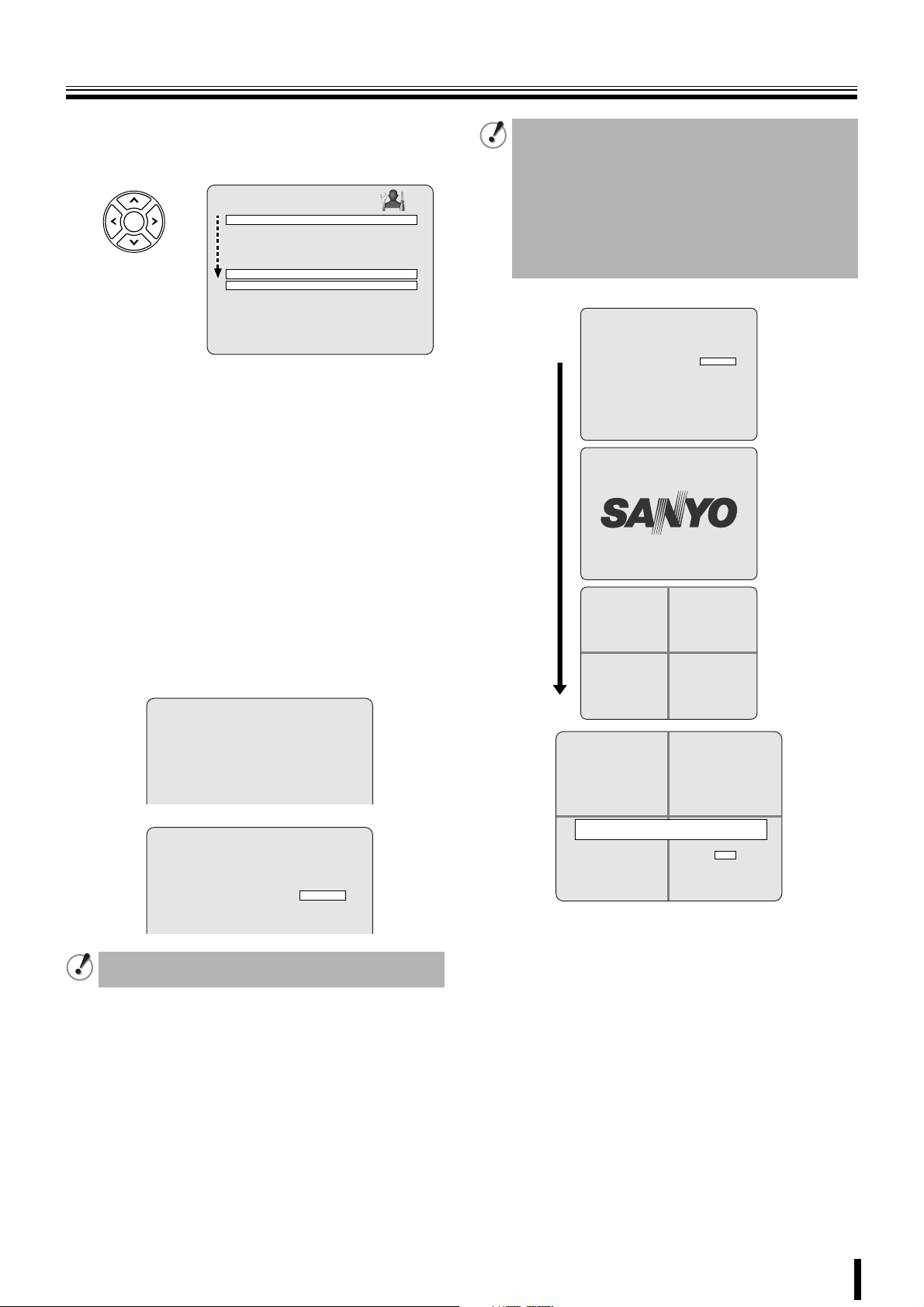
Press the MENU button.
1
The PASSWORD input screen is displayed.
2%
PASSWORD
- - - -
CH1
• To return to the previous screen, press the EXIT/
STOP button.
Press the button 1 four times to enter "1111" and
2
press the ENTER button.
The MAIN MENU screen is displayed.
•"1111" is the factory default setting password. We
recommend you change the password to avoid
unauthorized use. (P30)
1
2%
2006/07/14 08:06:09
2006/07/14 08:06:09
12
ON
Up: When connecting the general monitor to the video
output terminal
Down: When connecting a PC monitor to the VGA
terminal
POWERMODEAUTOMENU
The VGA terminal and the video output terminal cannot
be used simultaneously.
7
PASSWORD
* * * *
- - - -
CH1
MAIN MENU
RECORDLIVE SYSTEM
HDD SETNETWORK SERVICE
Page 17
Pre-operation preparation
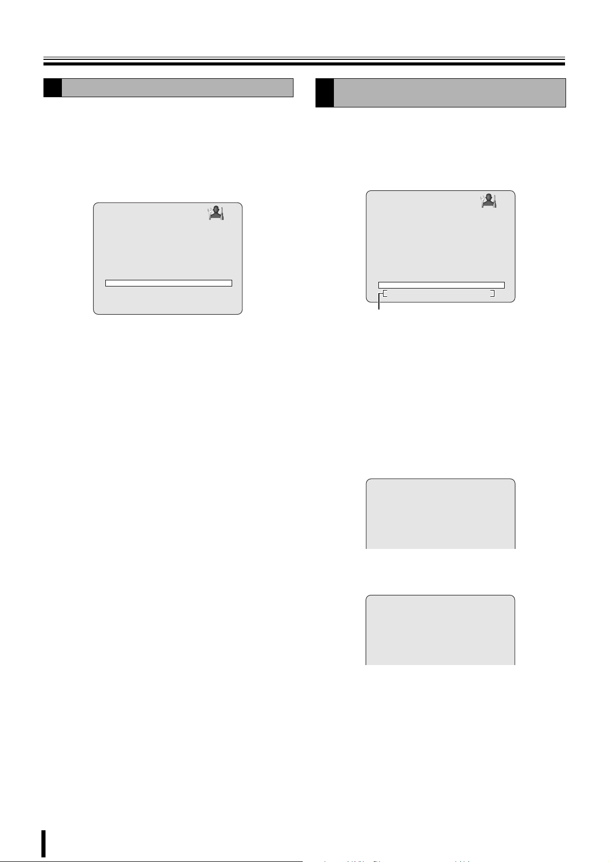
Press the control button (~) twice and select the
3
SYSTEM, press the ENTER button.
The SYSTEM settings screen is displayed.
SYSTEM
DVR ID DVR
DESCRIPTION
LOAD DEFAULT
ADMIN PASSWORD
NETWORK PASSWORD
DATE FORMAT YYYY/MM/DD
CLOCK SET
PTZ CONTROL
LANGUAGE ENGLISH
REMOTE CONTROLLER ID 0
D.S.T./SUMMER TIME OFF
Select DATE FORMAT using the control button
4
({|) and select the date display format using the
control button (}~).
• YYYY/MM/DD
(Example: 2006/12/15)
• MM/DD/YYYY
• DD/MM/YYYY
Select CLOCK SET using the control button ({|)
5
and press the ENTER button.
•YYYY-MM-DD
(Example: 2006-12-15)
• MM-DD-YYYY
• DD-MM-YYYY
The CLOCK SET screen is displayed.
b In the event that the clock is early
Reset the clock using the CLOCK SET, select "CONFIRM"
under "UPDATE DATE&TIME". The TIME MISMATCH screen
is displayed, select "YES".
•YES:
The videos between "SYSTEM TIME" and "HDD LAST
TIME" are lost.
•GO TEST MODE:
Do not select. (Maintenance mode)
UPDATE DATE&TIME
CANCEL CONFIRM
Select the date/time to be changed using the
6
control button (}~), select a value using the
control button ({|), repeat to set the date/time and
press the ENTER button.
The UPDATE DATE&TIME screen is displayed.
CLOCK SET
2006/12/15 10:20:30
UPDATE DATE&TIME
CONFIRMCANCEL
The time on this CLOCK SET screen has not been
calculated considering summer time.
Select CONFIRM using the control button (}~) and
7
press the ENTER button.
The screen switches to the "INITIALIZING..." screen.
The live videos as well as the set date/time are
displayed on the monitor.
INITIALIZING...
CH1 C CH2 C
CH3
CH3 C CH4 C
TIME MISMATCH.
WILL YOU ERASE INDEX?
IF YES, SOME DATA WILL BE ERASED FROM HDD.
CH1 R
IF THE DATA IS TO BE KEPT, SELECT GO TEST MODE.
2006-09-09 19:56:36
SYSTEM TIME:
2006-09-09 20:05:45
HDD LAST TIME:
CH3
CH2
CH4
CH2
YESGO TEST MODE
CH4
8
Page 18
Pre-operation preparation
Setting the language (LANGUAGE)
C
Follow steps 1 to 3 of the CLOCK SET procedure
1
Select LANGUAGE using the control button ({|)
2
and select the display language using the control
button (}~).
Once a language has been selected the display
language changes.
SYSTEM
DVR ID DVR
DESCRIPTION
LOAD DEFAULT
ADMIN PASSWORD
NETWORK PASSWORD
DATE FORMAT YYYY/MM/DD
CLOCK SET
PTZ CONTROL
LANGUAGE ENGLISH
REMOTE CONTROLLER ID 0
D.S.T./SUMMER TIME OFF
Language selection:
ENGLISH, 日本語 , DEUTSCH, Français, ESPAÑOL,
ITALIANO, ipllXTT ìRàX, 中文 (繁體) , POLSKI,
CESKY, óçhHBjlXT LRTX, Româna, Srpski, SVENSKA
Setting the summer time
D
(D.S.T./SUMMER TIME)
Summer time setting is available.
Select D.S.T./SUMMER TIME using the control
1
button ({|) and select "ON" using the control
button (}~).
It becomes possible to input summer time.
SYSTEM
DVR ID DVR
DESCRIPTION
LOAD DEFAULT
ADMIN PASSWORD
NETWORK PASSWORD
DATE FORMAT YYYY/MM/DD
CLOCK SET
PTZ CONTROL
LANGUAGE ENGLISH
REMOTE CONTROLLER ID 0
D.S.T./SUMMER TIME ON
BEGIN 2/1 0H
END 8/1 0H
Initial value
Select "BEGIN" using the control button ({|) and
2
press the ENTER button.
D.S.T./SUMMER TIME BEGIN is displayed.
Input the starting date (31 March, 23:00).
3
1 Display "0" using the control button ({|) and move
to the right using the control button (}~).
2 Display "3" using the control button ({|) and move
to the right using the control button (}~), repeat to
set other settings and press the ENTER button.
The summer time input selection screen is displayed
again.
D.S.T./SUMMER TIME BEGIN
0 3 / 3 1 2 3 H
Repeat the procedure to input the end date (31
4
August, 23:00).
D.S.T./SUMMER TIME END
0 8 / 3 1 2 3 H
9
Page 19
Monitoring the camera videos
A C B
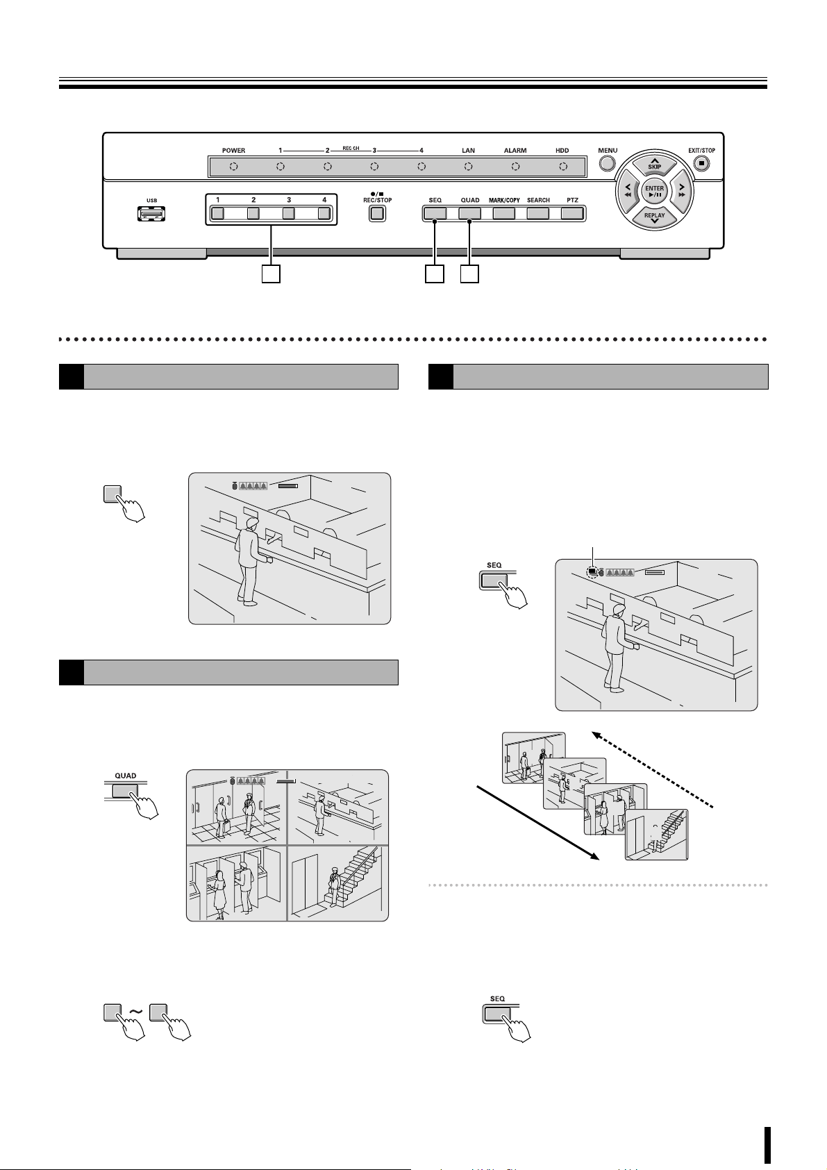
Single-screen display
A
Example: Displaying camera 2 on single-screen
Press "2" on the camera selection button.
1
The video of camera 2 is displayed on single-screen.
2
Quad-screen display
B
Displays the 4 cameras video connected at once.
Press the QUAD button.
1
The quad-screen is displayed.
CH2
2%
2006/07/14 08:06:09
C
2%
2006/07/14 09:04:54
Camera sequencing
C
Switches the cameras video in sequence.
Press the SEQ button while in single-screen
1
display.
The cameras automatically switch in sequence starting
with the channel of the camera being displayed. If there
is an audio input, the audio also switches in channel
sequence order.
Sequence display
2%
2006/07/14 09:04:54
CH2
C
1
2
CH1 C
CH3 C
To return to single-screen press any of the camera
2
selection buttons.
14
CH2 C
CH4 C
3
4
Memo: The sequence interval from one camera video to
another can be set. (P25)
Press the SEQ button once operations are
2
complete.
The sequence mode is cancelled.
10
Page 20
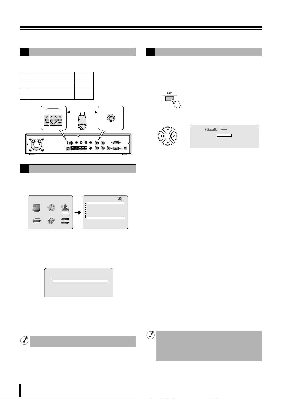
Operating the PTZ camera
If a PTZ camera is connected to the RS422/485 terminal, Pan/Tilt, Zoom/Focus operations are available from this unit.
Connection
1
Connect the RS422/485 terminal and the camera using a
twisted pair cable.
RS422 RS485
1
TX+ (+Transmit Data)
2
TX- (-Transmit Data)
3
RX+ (+Receive Data)
4
RX- (-Receive Data)
RS-422/485
TX+ TX- RX+ RX-
1234
Settings
2
Press the MENU button (the MAIN MENU is
1
displayed) and select SYSTEM using the control
A
B
–
–
button (}~).
MAIN MENU
RECORDLIVE SYSTEM
HDD SETNETWORK SERVICE
DVR ID DVR
DESCRIPTION
LOAD DEFAULT
ADMIN PASSWORD
NETWORK PASSWORD
DATE FORMAT YYYY/MM/DD
CKLOCK SET
PTZ CONTROL
LANGUAGE ENGLISH
REMOTE CONTROLLER ID 0
D.S.T./SUMMER TIME OFF
SYSTEM
• A password is requested when pressing the MENU
button. (P7)
Place the cursor on PTZ CONTROL and press the
2
ENTER button.
The PTZ CONTROL screen is displayed.
PTZ CONTROL
DATA SPEED 19200 14400 9600 4800 2400
CHANNEL 1 2 3 4
PROTOCOL - - - ADDRESS 0
Place the cursor on the settings item and setting.
3
DATA SPEED: Selecting the communication speed
CHANNEL: Selecting a connected channel
PROTOCOL: Selecting the type of protocol
ADDRESS: Selecting the camera ID (0-63)
When several cameras are connected, select the same
protocol for all cameras.
Press the EXIT/STOP button once the settings are
4
complete.
Operation
3
Select the number of the dome camera connected
1
using the camera selection button.
Press the PTZ button.
2
The control screen is displayed.
Controlling the camera
3
2%
2006/07/14 17:25:37
PAN/TILT
ZOOM/FOCUS
INITIALIZE
b Pan/Tilt operations
1 Select "PAN/TILT" using the control button ({|)
and press the ENTER button.
2 Adjust the tilt position using the control button ({|)
and adjust the pan position using the control button
(}~).
• The following message is displayed on the screen
during operations.
Up/Down key: Tilt Up/Down
Left/Right key: Pan Left/Right
b Zoom/Focus operations
1 Select "ZOOM/FOCUS" using the control button
({|) and press the ENTER button.
2 Adjust the zoom using the control button ({|) and
adjust the focus position using the control button
(}~).
• The following message is displayed on the screen
during operations.
Up/Down key: Zoom In/Out
Left/Right key: Focus Near/Far
b Initializing the camera position
Select "INITIALIZE" using the control button ({|) and
press the ENTER button.
• Once the initialization is complete, the following
message is displayed on the screen and the
adjustment position is reset to its default values.
"INITIALIZE SUCCESS!"
Press the EXIT/STOP button once operation are
4
complete.
• If a PTZ camera is not connected to this unit, the
following message is displayed on the screen.
"Please set up a camera type in setup menu."
• The terminator settings of this unit are set to "ON".
Consult the dealership where this unit was purchased
for any changes.
11
Page 21

Recording
1 2
This unit allows the following recording modes.
Select the recording mode, recording resolution, frame rate
and video quality from "RECORD" under the MAIN MENU.
(P27)
The symbol on the right side of each recording mode (Ex: R)
is displayed while recording is in progress.
b Types of recording modes
A Real time recording (R) .................................. P12
Records manually videos being monitored.
B CONTINUOUS recording (C) ........................... P13
Records continuously when this unit is turned on.
C BY MOTION recording (M)............................... P13
Records when set off by the motion sensor integrated in this
unit.
D BY EXT. SENSOR recording (S)...................... P14
Records when set off by a sensor connected to the external
sensor (SENSOR) terminal of this unit.
E BY SCHEDULE recording................................ P15
Records according to the daily time slot set under the
SCHEDULE screen of the recording settings.
• The initial screen requests a password. (P24)
• It is possible to cancel the password request.
See "Settings for no password" (P30)
Real time recording
A
Press the REC/STOP button while monitoring live
1
videos.
"R" is displayed on the recording display and recording
starts.
2%
2%
2006/07/14 08:06:09
2006/07/14 08:06:09
CH1
R
Memo: • Setting the OVERWRITE (P37)
ON: Overwrites earlier data once the hard disk
capacity is full.
OFF: Stops recording operations once the hard
disk capacity is full.
Press the EXIT/STOP button once operations are
2
complete.
"R" disappears from the recording display and real time
recording is stopped.
• When recording rate is high, the audio may be difficult
to hear at the time of playback and playback time may
increase.
• Recording time varies depending on the screen being
recorded. Furthermore, recording rate may decrease
depending on the settings.
12
Page 22

Recording
CONTINUOUS recording
B
Recording starts automatically when this unit is
1
turned on.
"C" is displayed on the screen. The connected cameras
are simultaneously recorded.
The recording mode can be changed using
RECORDING under RECORD settings. Settings, such
as image quality, can also be set. (P27)
2%2%
2006/07/14 09:04:54
CH1 C
CH3 C
To stop recording, select RECORDING under
2
RECORD settings using the control button ({|)
CH2 C
CH4 C
and select "DISABLE" using the control button
(}~).
“C” disappears.
Select MOTION ZONE using the control button
3
({|) and select the PARTIAL ZONE using the
control button (}~), press the ENTER button.
The motion setting screen is displayed.
• PARTIAL ZONE • FULL ZONE
If FULL ZONE is selected, the motion setting screen is
not displayed. Only set the level of sensitivity for MOTION
SENSITIVITY.
RECORD
RESOLUTION QUAD
CHANNEL CH1
FRAME RATE 1 f/s
QUALITY NORMAL
RECORDING BY MOTION
MOTION ZONE PARTIAL ZONE
MOTION SENSITIVITY 7
SENSOR TYPE -- PRE RECORD ON
POST EVENT RECORD 5 SECONDS
ALARM OFF
ALARM DURATION 5 SECONDS
AUDIO OFF
TIMER SET
RECORD
RESOLUTION QUAD
CHANNEL CH1
FRAME RATE 1 f/s
QUALITY NORMAL
RECORDING DISABLE
MOTION ZONE FULL ZONE
MOTION SENSITIVITY 7
SENSOR TYPE -- PRE RECORD ON
POST EVENT RECORD 5 SECONDS
ALARM OFF
ALARM DURATION 5 SECONDS
AUDIO OFF
TIMER SET
BY MOTION recording
C
A motion sensor can be set for each channel.
Adjusting the following settings using the control
1
button ({|}~).
• RESOLUTION
• CHANNEL
Select RECORDING using the control button ({|)
2
and select BY MOTION using the control button
• FRAME RATE
•QUALITY
(}~).
Detection
frame
Select the sensor detection position using the
4
control button ({|}~) and press the ENTER
button.
The frame set for the sensor detection is grainy.
Select a sensor detection position by repeating the
operation.
Select MOTION SENSITIVITY using the control
5
button ({|) and select the level of sensitivity
using the control button (}~).
Selections: 1-9 (Low sensitivity)
Select PRE RECORD using the control button ({|)
6
and select the pre recording as necessary using the
control button (}~).
Select POST EVENT RECORD using the control
7
button ({|) and select the recording time as
necessary using the control button (}~).
Selections: 2 - 30 SECONDS
Press the EXIT/STOP button once operations are
8
complete.
Press the EXIT/STOP button repeatedly to return to the
live video.
13
Page 23

Recording
BY EXT. SENSOR recording
D
An external sensor can be connected to each channel.
Connecting an external switch to an external
1
sensor terminal.
Camera
(Sold separately)
1234
Monitor
(Sold separately)
OUT
b Output settings at the time of external switch
operation
When a motion sensor of this unit or an external sensor is
activated, a relay signal is output to the external alarm device
connected to the ALARM OUT terminal. It is normally open.
Connecting an external alarm to the OUT terminal
1
of the external sensor.
Camera
POWERMODEAUTOMENU
Maximum current:
0.5A/125V AC
Maximum voltage:
1A/30V DC
(Sold separately)
1234
Power
source
Monitor
(Sold separately)
POWERMODEAUTOMENU
OUT
Set the following items using the control button
2
({|}~).
• RESOLUTION
• CHANNEL
Select RECORDING using the control button ({|)
3
and select BY EXT. SENSOR using the control
• FRAME RATE
•QUALITY
button (}~).
RECORD
RESOLUTION QUAD
CHANNEL CH1
FRAME RATE 1 f/s
QUALITY NORMAL
RECORDING BY EXT.SENSOR
MOTION ZONE FULL ZONE
MOTION SENSITIVITY 7
SENSOR TYPE -- PRE RECORD ON
POST EVENT RECORD 5 SECONDS
ALARM OFF
ALARM DURATION 5 SECONDS
AUDIO OFF
TIMER SET
Select SENSOR TYPE using the control button
4
({|) and select detection mode using the control
button (}~).
Select PRE RECORD using the control button ({|)
5
and select the pre recording as necessary using the
control button (}~).
Select ALARM using the control button ({|) and
2
select ON using the control button (}~).
Select ALARM DURATION using the control button
3
({|) and select the alarm signal output duration
using the control button (}~).
Selections: 1 - 60 SECONDS
RECORD
RESOLUTION QUAD
CHANNEL CH1
FRAME RATE 1 f/s
QUALITY NORMAL
RECORDING BY EXT.SENSOR
MOTION ZONE FULL ZONE
MOTION SENSITIVITY 7
SENSOR TYPE -- PRE RECORD ON
POST EVENT RECORD 5 SECONDS
ALARM OFF
ALARM DURATION 5 SECONDS
AUDIO OFF
TIMER SET
Press the EXIT/STOP button once operations are
4
complete.
Press the EXIT/STOP button repeatedly to return to the
live screen.
Select POST EVENT RECORD using the control
6
button ({|) and select the recording time as
necessary using the control button (}~).
Selections: 2 - 30 SECONDS
Press the EXIT/STOP button once operations are
7
complete.
Press the EXIT/STOP button repeatedly to return to the
live screen.
14
Page 24

Recording
BY SCHEDULE recording
E
Adjusting the following settings using the control
1
button ({|}~).
• RESOLUTION
• CHANNEL
Select RECORDING using the control button ({|)
2
and select BY SCHEDULE using the control button
• FRAME RATE
•QUALITY
(}~).
The following settings are necessary when performing
sensor detection.
• MOTION ZONE
• MOTION SENSITIVITY
• SENSOR TYPE
• PRE RECORD
• POST EVENT RECORD
Select TIMER SET using the control button ({|)
3
and press the ENTER button.
When the channel 1 is selected, "TIMER SET-CH1"
screen is displayed.
RECORD
RESOLUTION QUAD
CHANNEL CH1
FRAME RATE 1 f/s
QUALITY NORMAL
RECORDING BY SCHEDULE
MOTION ZONE FULL ZONE
MOTION SENSITIVITY 7
SENSOR TYPE -- PRE RECORD ON
POST EVENT RECORD 5 SECONDS
ALARM OFF
ALARM DURATION 5 SECONDS
AUDIO OFF
TIMER SET
Select ALL or each day using the control button
4
({|) and set the recording mode using the ENTER
button.
Repeat the procedure to set a different recording mode.
-: DISABLE (Does not record)
C: CONTINUOUS recording
M: BY MOTION recording
S: BY EXT. SENSOR recording
Input example:
TIMER SET-CH1
COPY FROM CH1
COPY TO CH1
0 3 6 9 12 15 18 21 24
ALL
SUN - - - - - - - - - - - - - - - - - - - - -
CSM
MON - - - - - - - - - - - - - - - - - - - - -
SCM
TUE - - - - - - - - - - - - - - - - - - - - -
SMM
WED - - - - - - - - - - - - - - - - - - - - - - - -
THU - - - - - - - - - - - - - - - - - - - - - - - -
FRI - - - - - - - - - - - - - - - - - - - - - - - -
SAT - - - - - - - - - - - - - - - - - - - - - - - -
• Selecting an identical setting for every day
(Example: CONTINUOUS):
Move the cursor to "ALL", the display turns red.
Repeatedly pressing the ENTER button sets the
same setting for every day.
TIMER SET-CH1
COPY FROM CH1
COPY TO CH1
0 3 6 9 12 15 18 21 24
ALL
SUN C C C C C C C C C C C C C C C C C C C C C C C C
MON C C C C C C C C C C C C C C C C C C C C C C C C
TUE C C C C C C C C C C C C C C C C C C C C C C C C
WED C C C C C C C C C C C C C C C C C C C C C C C C
THU C C C C C C C C C C C C C C C C C C C C C C C C
FRI C C C C C C C C C C C C C C C C C C C C C C C C
SAT C C C C C C C C C C C C C C C C C C C C C C C C
• Selecting the same setting for a whole day
(Example: MOTION):
Move the cursor to the day, the display turns red.
Repeatedly pressing the ENTER button sets the
same setting for the whole day.
TIMER SET-CH1
COPY FROM CH1
COPY TO CH1
0 3 6 9 12 15 18 21 24
ALL
SUN - - - - - - - - - - - - - - - - - - - - - - - -
M M M M M M M M M M M M M M M M M M M M M M M M
MON
TUE - - - - - - - - - - - - - - - - - - - - - - - -
WED - - - - - - - - - - - - - - - - - - - - - - - -
THU - - - - - - - - - - - - - - - - - - - - - - - -
FRI - - - - - - - - - - - - - - - - - - - - - - - -
SAT - - - - - - - - - - - - - - - - - - - - - - - -
• Selecting the same setting for a specified time
only every day (Example: MOTION):
Move the cursor to "ALL" and move the cursor to the
specified time using the control button (~), the
longitudinal bar changes to = (red). Press the
ENTER button repeatedly to set the same setting
(M).
TIMER SET-CH1
COPY FROM CH1
COPY TO CH1
0 3 6 9 12 15 18 21 24
=
ALL
M
SUN - - - - - - - - - - - - - - - - - - - - - - -
M
MON - - - - - - - - - - - - - - - - - - - - - - -
M
TUE - - - - - - - - - - - - - - - - - - - - - - -
M
WED - - - - - - - - - - - - - - - - - - - - - - -
M
THU - - - - - - - - - - - - - - - - - - - - - - -
M
FRI - - - - - - - - - - - - - - - - - - - - - - -
M
SAT - - - - - - - - - - - - - - - - - - - - - - -
Press the EXIT/STOP button once operations are
5
complete.
Press the EXIT/STOP button repeatedly to return to the
live screen.
15
Page 25

Recording
b Copying a set recording schedule to other channels
Example 1
Set the channel 1 schedule and press the EXIT/
1
STOP button.
Copying the channel 1 schedule to channel
3 (COPY FROM)
The RECORD screen is displayed again.
TIMER SET-CH1
COPY FROM CH1
COPY TO CH1
0 3 6 9 12 15 18 21 24
ALL
SUN - - - - - - - - - - - - - - -
CMS C MS CMS
MON - - - - - - - - - - - - - -
SCMS CMS CMS
SCMS CMS CMS
TUE - - - - - - - - - - - - - -
SMCMS CMSCMS
WED - - - - - - - - - - - - -
SMCMS CMSCM
THU - - - - - - - - - - - - - -
FRI - - - - - - - - - - - - -
SAT - - - - - - - - - - - - - -
Select CHANNEL using the control button ({|)
2
and select CH3 using the control button (}~).
Select TIMER SET using the control button ({|)
3
and press the ENTER button.
SMCMS CMSCMC
SMCMS CMSCC
The "TIMER SET-CH3" screen is displayed.
RECORD
RESOLUTION QUAD
CHANNEL CH3
FRAME RATE 1 f/s
QUALITY NORMAL
RECORDING CONTINUOUS
MOTION ZONE FULL ZONE
MOTION SENSITIVITY 7
SENSOR TYPE -- PRE RECORD ON
POST EVENT RECORD 5 SECONDS
ALARM OFF
ALARM DURATION 5 SECONDS
AUDIO OFF
TIMER SET
TIMER SET-CH3
COPY FROM CH1
COPY TO CH1
0 3 6 9 12 15 18 21 24
ALL
SUN - - - - - - - - - - - - - - -
CMS C MS CMS
Example 2
Set the channel 1 schedule and select COPY TO
1
using the control button ({|), select CH2 using
Copying the channel 1 schedule to channel
2 (COPY TO)
the control button (}~) and press the ENTER
button.
The CH1 schedule is copied to CH2.
TIMER SET-CH1
COPY FROM CH1
COPY TO CH2
0 3 6 9 12 15 18 21 24
ALL
SUN - - - - - - - - - - - - - - - -
CMS CMC SC
MON - - - - - - - - - - - - - - - -
CMSCMC SC
TUE - - - - - - - - - - - - - - - -
CMS CMC SC
WED - - - - - - - - - - - - - - - -
CMSCMC SC
THU - - - - - - - - - - - - - - - -
CMS CMC SC
FRI - - - - - - - - - - - - - - - -
CMSCMC SC
SAT - - - - - - - - - - - - - - - -
CMS CMC SC
Press the EXIT/STOP button.
2
The RECORD screen is displayed again.
Select CHANNEL using the control button ({|)
3
and select CH2 using the control button (}~).
Select TIMER SET using the control button ({|)
4
and press the ENTER button.
The "TIMER SET-CH2" screen is displayed. The CH1
schedule is copied to CH2.
TIMER SET-CH2
COPY FROM CH1
COPY TO CH1
0 3 6 9 12 15 18 21 24
ALL
SUN - - - - - - - - - - - - - - - -
CMS CMC SC
MON - - - - - - - - - - - - - - - -
CMSCMC SC
TUE - - - - - - - - - - - - - - - -
CMS CMC SC
WED - - - - - - - - - - - - - - - -
CMSCMC SC
THU - - - - - - - - - - - - - - - -
CMS CMC SC
FRI - - - - - - - - - - - - - - - -
CMSCMC SC
SAT - - - - - - - - - - - - - - - -
CMS CMC SC
Select COPY FROM using the control button ({|)
4
and select CH1 using the control button (}~),
press the ENTER button.
The CH1 recording schedule is copied to CH3.
Press the EXIT/STOP button once operations are
5
complete.
Press the EXIT/STOP button repeatedly to return to the
live screen.
16
Page 26

Playing back recorded videos
The following recorded videos searching methods are available.
b EVENT SEARCH (P18)
Search through a recorded video list by setting the date on the calendar
display, the camera channel and specify the type of recording.
SEARCH
2006/07
1
2 3 4 5 6 7 8
9 10 11 12 13 14 15
16 17 18 19 20 21 22
23 24 25 26 27 28 29
30 31
2%
2%
EVENT SEARCH
TIMELINE SEARCH
T/D SEARCH
GO FIRST
GO LAST
BOOKMARK
2006/07/14 17:25:37
LOG
CH1
C
b BOOKMARK (P20)
Search through copied still images or moving
videos.
CHANNEL
TYPE
b TIMELINE SEARCH (P19)
Searching for an event by setting the date, time on the timeline.
2006/07
1
2 3 4 5 6 7 8
9 10 11 12 13 14 15
16 17 18 19 20 21 22
23 24 25 26 27 28 29
30 31
CHANNEL
TYPE
b T/D SEARCH (P19)
Searching for an event by setting the date, time numerically.
1 2 3 4
A M S R
SEARCH
1 2 3 4
A M S R
C
SEARCH
2006/07/14 03:00:00
0 3 6 9 12 15 18 21 24 HOUR
1
2
3
4
0 10 20 30 40 50 60 MIN
1
2
C
3
4
b The function of each button during
playback.
The fast forward speed changes each
e
f
SKIP Jumps the video 1 minute forward
REPLAY Jumps the video 1 minute backward
c/h
EXIT/STOP
b
time it is pressed, the symbol is displayed
on the bottom right of the screen.
c
(Standard) → 2e(X2) → 4e→ 8e
The fast rewind speed changes each
time it is pressed, the symbol is displayed
on the bottom right of the screen.
d
(Standard) → 2f(X2) → 4f→ 8f
Pause (Still image display)
Press again to restart playback.
Stops a playback in progress
SEARCH
2006/07/14 17:17:00
b GO FIRST (P19)
Searching the first (oldest) recording data.
b GO LAST (P20)
Searching the last (newest) recording data.
b LOG (P20)
Viewing the operation / activities (LOG) of this unit on a specified date.
LOG
2006/07
1
2 3 4 5 6 7 8
9 10 11 12 13 14 15
16 17 18 19 20 21 22
23 24 25 26 27 28 29
30 31
LIST
2006/07/14 (1/1)
<03:28:37> System Start
<08:02:58> System Start
<08:04:20> Manual Record Start
<08:04:35> Manual Record Stop
<08:04:50> Manual Record Start
<08:05:03> Manual Record Stop
<08:06:34> Enter Setup
<17:03:36> System Start
<17:05:04> System Start
<17:08:07> Manual Record Start
<17:08:52> Manual Record Stop
17
Page 27

Playing back recorded videos
EVENT SEARCH
A
1 2 6 7
Press the SEARCH button.
1
The menu screen is displayed.
2%
2%
EVENT SEARCH
TIMELINE SEARCH
T/D SEARCH
GO FIRST
GO LAST
LOG
BOOKMARK
Select EVENT SEARCH using the control button
2
({|) and press the ENTER button.
The SEARCH screen is displayed.
Select the date you want to search using the
3
control button ({|}~) and press the ENTER
button.
The cursor moves to CHANNEL.
If recordings are available, the date is displayed in red.
• : Indicates that there are recordings in the
previous month.
: Indicates that there are recordings in the next
month.
Move the cursor to the day of the first recording in
the month displayed by the calendar, pressing the }
button displays the previous month of the calendar.
Move the cursor to the day of the last recording in
the month displayed by the calendar, pressing the ~
button displays the next months of the calendar.
2006/07/14 17:25:37
Select the type of recording (Mode) to be searched
5
using the control button (}~) and press the
ENTER button.
A: All types (ALL)
M: Recording activated by motion detection
(BY MOTION)
S: Recording activated by sensor detection
(BY EXT. SENSOR)
R: Real time recording
C: Continuous recording (CONTINUOUS)
Example:
Searching recordings activated by the motion detection
(M) of the channel 2 of the camera
CHANNEL
TYPE
1 2 3 4
A M S R
C
The list screen is displayed.
Select the videos to be played back using the
6
control button ({|), and press the ENTER button.
Playback starts.
If the list continues on several pages, use the control
button (}~) to change pages.
LIST
2006/07/14 (1/1)
<08:04:20> CH2:MOTION
<08:04:50> CH2:MOTION
<17:08:07> CH2:MOTION
SEARCH
2006/07
1
2 3 4 5 6 7 8
9 10 11 12 13 14 15
16 17 18 19 20 21 22
23 24 25 26 27 28 29
30 31
CHANNEL
TYPE
Select a channel with the control button (}~) and
4
press the ENTER button.
1 2 3 4
A M S R
The cursor moves to TYPE.
• To select all the channels, select .
C
Playback in progress display
Press the EXIT/STOP button once operations are
7
complete.
CH2
Press the EXIT/STOP button repeatedly to return to the
live screen.
18
Page 28

Playing back recorded videos
TIMELINE SEARCH
B
Press the SEARCH button.
1
The search menu screen is displayed.
Select TIMELINE SEARCH using the control button
2
({|) and press the ENTER button.
The SEARCH screen is displayed.
If recordings are available, the date is displayed in red.
• : Indicates that there are recordings in the
previous month.
: Indicates that there are recordings in the next
month.
Move the cursor to the day of the first recording in
the month displayed by the calendar, pressing the }
button displays the previous month of the calendar.
Move the cursor to the day of the last recording in
the month displayed by the calendar, pressing the ~
button displays the next months of the calendar.
SEARCH
2006/07
1
2 3 4 5 6 7 8
9 10 11 12 13 14 15
16 17 18 19 20 21 22
23 24 25 26 27 28 29
30 31
Select the date to be played back using the control
3
button ({|}~) and press the ENTER button.
The timeline screen is displayed.
• The upper bar on the screen shows 24 hours and
the lower bar 60 minutes. Time sections with a
recording are represented by a red line.
• A yellow longitudinal line is displayed at the
beginning of each icon to select playback. Move this
longitudinal line to the right and select the
recordings with the red line.
1 Channel number
2 All channel selected display:
SEARCH
2006/07/14 03:00:00
0 3 6 9 12 15 18 21 24 HOUR
1
1
2
1
2
3
4
0 10 20 30 40 50 60 MIN
1
2
3
4
Move the yellow longitudinal line to the time
5
sections to be played using the control button
(}~) and press the ENTER button.
Playback starts.
0 10 20 30 40 50 60 MIN
1
2
3
4
• When all the channels have been selected,
becomes red.
• Each channel can be selected using the control
buttons.
Press the EXIT/STOP button once operations are
6
complete.
Press the EXIT/STOP button repeatedly to return to the
live screen.
T/D SEARCH
C
Press the SEARCH button.
1
The search menu screen is displayed.
Select T/D SEARCH using the control button ({|)
2
and press the ENTER button.
The SEARCH screen is displayed.
Select the date and time to be played back using
3
the control button (}~) and input a value using the
control button ({|).
SEARCH
2006/07/14 17:17:00
Press the ENTER button.
4
Playback starts.
• If no videos were recorded for the specified date, the
video closest to the specified date are played back.
Press the EXIT/STOP button once operations are
5
complete.
Press the EXIT/STOP button repeatedly to return to the
live screen.
Move the yellow longitudinal line to the time
4
sections to be played using the control button
(}~) and press the ENTER button.
The yellow longitudinal line moves down to the next line.
0 3 6 9 12 15 18 21 24 HOUR
1
2
3
4
If audio has been recorded a green line is displayed
under the red line.
19
GO FIRST
D
Press the SEARCH button.
1
The menu screen is displayed.
Select GO FIRST using the control button ({|) and
2
press the ENTER button.
The first recording is played back.
Press the EXIT/STOP button once operations are
3
complete.
Press the EXIT/STOP button repeatedly to return to the
live screen.
Page 29

Playing back recorded videos
GO LAST
E
Press the SEARCH button.
1
The menu screen is displayed.
Select GO LAST using the control button ({|) and
2
press the ENTER button.
The last recording is played back.
Press the EXIT/STOP button once operations are
3
complete.
Press the EXIT/STOP button repeatedly to return to the
live screen.
LOG
F
Press the SEARCH button.
1
The menu screen is displayed.
Select LOG using the control button ({|) and
2
press the ENTER button.
The LOG screen is displayed.
If recordings are available, the date is displayed in red.
• : Indicates that there are recordings in the
previous month.
: Indicates that there are recordings in the next
month.
Move the cursor to the day of the first recording in
the month displayed by the calendar, pressing the }
button displays the previous month of the calendar.
Move the cursor to the day of the last recording in
the month displayed by the calendar, pressing the ~
button displays the next months of the calendar.
BOOKMARK
G
Perform the mark operation of the desired live video. The
marked event and recording list can be displayed and played
back.
Press the SEARCH button.
1
The menu is displayed.
2%
2%
EVENT SEARCH
TIMELINE SEARCH
T/D SEARCH
GO FIRST
GO LAST
BOOKMARK
Select BOOKMARK using the control button ({|)
2
and press the ENTER button.
2006/07/14 17:25:37
LOG
The BOOKMARK screen is displayed.
If recordings are available, the date is displayed in red.
• : Indicates that there are recordings in the
previous month.
: Indicates that there are recordings in the next
month.
Move the cursor to the day of the first recording in
the month displayed by the calendar, pressing the }
button displays the previous month of the calendar.
Move the cursor to the day of the last recording in
the month displayed by the calendar, pressing the ~
button displays the next months of the calendar.
Select an event which date is displayed in red using
3
the control button ({|}~) and press the ENTER
button.
LIST is displayed.
LOG
2006/07
1
2 3 4 5 6 7 8
9 10 11 12 13 14 15
16 17 18 19 20 21 22
23 24 25 26 27 28 29
30 31
Select the date to be displayed using the control
3
button ({|}~) and press the ENTER button.
The LIST screen is displayed.
• If several lists are available, the previous or next
LIST can be viewed using the control button (}~).
LIST
2006/07/14 (1/1)
<03:28:37> System Start
<08:02:58> System Start
<08:04:20> Manual Record Start
<08:04:35> Manual Record Stop
<08:04:50> Manual Record Start
<08:05:03> Manual Record Stop
<08:06:34> Enter Setup
<17:03:36> System Start
<17:05:04> System Start
<17:08:07> Manual Record Start
<17:08:52> Manual Record Stop
Press the EXIT/STOP button once operations are
4
complete.
Press the EXIT/STOP button repeatedly to return to the
live screen.
BOOKMARK
2006/07
1
2 3 4 5 6 7 8
9 10 11 12 13 14 15
16 17 18 19 20 21 22
23 24 25 26 27 28 29
30 31
LIST
2006/07/14 (1/1)
<17:20:48> LIVE JPEG
<17:21:04> LIVE JPEG
<17:23:02> CH1 AVI 2SEC
Select the date to be played back from the list using
4
the control button ({|) and press the ENTER
button.
The still image is displayed.
20
Page 30

Copying the recorded videos to a USB device
Your choice of videos can be copied to a USB device. Selecting these videos is called marking. Still images of live videos and still
and moving videos of playbacks in progress can be selected.
Marking and copying live videos
A
Connect the USB memory to the USB terminal,
1
copying operations become available.
• Connect the USB memory.
USB memory
Press the MARK/COPY button at the scene to be
2
copied while monitoring live videos.
The BOOKMARK screen is displayed.
Select YES using the control button (}~) and
3
press the ENTER button.
The video on channel 1 is marked as a still image. The
message "BOOKMARK SUCCESS!" is displayed on
the screen.
Press the SEARCH button.
4
The search menu screen of channel 1 is displayed.
2%2%
EVENT SEARCH
TIMELINE SEARCH
T/D SEARCH
GO FIRST
GO LAST
LOG
BOOKMARK
CH1
C
Select BOOKMARK using the control button ({|)
5
and press the ENTER button.
The BOOKMARK screen is displayed.
If recordings are available, the date is displayed in red.
• : Indicates that there are recordings in the
previous month.
: Indicates that there are recordings in the next
month.
Move the cursor to the day of the first recording in
the month displayed by the calendar, pressing the }
button displays the previous month of the calendar.
Move the cursor to the day of the last recording in
the month displayed by the calendar, pressing the ~
button displays the next months of the calendar.
2006/07/14 17:25:37
2%
2%
2006/07/14 17:25:37
BOOKMARK
NO
YES
CH1 C
Once copying to the USB memory starts, the LAN is
disconnected.
BOOKMARK
2006/07
1
2 3 4 5 6 7 8
9 10 11 12 13 14 15
16 17 18 19 20 21 22
23 24 25 26 27 28 29
30 31
Select the marked date using the control button
6
({|}~) and press the ENTER button.
The LIST screen is displayed.
Select the videos to be copied to the USB device
7
using the control button ({|) and press the
ENTER button.
Still images are displayed.
LIST
2006/07/14 (1/1)
<17:20:48> LIVE JPEG
<17:21:04> LIVE JPEG
<17:23:02> CH1 AVI 2SEC
21
Page 31

Copying the recorded videos to a USB device
Press the MARK/COPY button.
8
The BACKUP USB DEVICE screen is displayed.
2%
2%
BACKUP USB DEVICE
CD-RW
Select USB STICK (Example) to where the selected
9
videos will be copied using the control button (}~)
and press the ENTER button.
The confirmation screen is displayed.
2%
2%
SAVE?
YES
CH1 C
USB STICK
CH1 C
2006/07/14 17:25:37
NO
2006/07/14 17:25:37
Marking and copying playback videos
B
Connect the USB memory to the USB terminal,
1
copying operations become available.
• Connect the USB memory.
Press the SEARCH button, the videos to be copied
2
are played back from the LIST. (P18)
Press the MARK/COPY button when the videos to
3
be copied are displayed.
The video pauses and the BOOKMARK screen is
displayed.
BOOKMARK
STILL VIDEO
CH1
2006/07/14 17:25:37
Select YES using the control button (}~) and
À
press the ENTER button.
• The message "SAVING" is displayed and the videos
are saved on the USB memory. Once the saving
operation is complete the message "SAVE
SUCCESS" is displayed.
• If no USB memory is connected, the warning
message "CHECK FAIL" is displayed.
Press the EXIT/STOP button once operations are
Á
complete.
Press the EXIT/STOP button repeatedly to return to the
live screen.
Repeating marking operations will result in overwriting.
Perform copy operations soon after marking the videos.
Select VIDEO (Example) using the control buttons
4
(}~) and press the ENTER button.
The DURATION screen is displayed.
If STILL was selected:
The videos are marked as still images and the
message "STILL OK" is displayed.
DURATION
8 0 0
CH1
Specify the duration to be recorded (Seconds)
5
using the control button ({|}~) and press the
ENTER button.
The videos are marked as moving videos and the
message "VIDEO OK" is displayed.
For copy operations, perform the operations
6
"4 Press the SEARCH button." of the " A Marking
and copying live videos".
Memo: Videos are saved in the AVI format and can be played
back using Windows Media Player
format compatible PC media player software. If the
video cannot be played back with those software,
install Codec (FFDShow) from the supplied
CD-ROM.
TM
or other AVI
22
Page 32

Configuration and function of the Menu settings
b LIVE settings (P25)
To perform adjustments related to live
videos monitoring such as sequencing
settings and each camera video
adjustments.
LIVE
OSD ON
SEQUENCE OFF
SEQ-DWELL TIME 2 SECONDS
EVENT BEEP OFF
OSD CONTRAST 80
CHANNEL CH1
DISPLAY ON
SEQ LIST ON
BRIGHTNESS 50
CONTRAST 50
HUE 0
SATURATION 50
VGA SCREEN MODE FULL
ERROR ALARM OFF
MAIN MENU
2%
2006/07/14 17:25:37
b RECORD settings (P27)
To perform adjustments related to
recordings such as resolution, the
recording mode for each channel,
video quality, motion and alarm
settings.
RECORD
RESOLUTION QUAD
CHANNEL CH1
FRAME RATE 1 f/s
QUALITY NORMAL
RECORDING CONTINUOUS
MOTION ZONE FULL ZONE
MOTION SENSITIVITY 7
SENSOR TYPE -- PRE RECORD ON
POST EVENT RECORD 5 SECONDS
ALARM OFF
ALARM DURATION 5 SECONDS
AUDIO OFF
TIMER SET
MAIN MENU
b SYSTEM settings (P29)
To perform settings carried out by the
manager, such as setting initialization
and password, date and time,
language and PTZ camera settings.
SYSTEM
DVR ID DVR
DESCRIPTION
LOAD DEFAULT
ADMIN PASSWORD
NETWORK PASSWORD
DATE FORMAT YYYY/MM/DD
CLOCK SET
PTZ CONTROL
LANGUAGE ENGLISH
REMOTE CONTROLLER ID 0
D.S.T./SUMMER TIME OFF
PASSWORD
- - - -
CH1 C
(See P7)
b NETWORK settings (P33)
To perform remote operations by
network and PC connection.
NETWORK
PORT 5445
CLIENT ACCESS ON
BANDWIDTH SAVING ON
NETWORK TYPE DHCP
DDNS OFF
SEND E-MAIL
LIVE
HDD SETNETWORK
SYSTEMRECORD
SERVICE
b HDD SET settings (P37)
Settings related to the hard disk such
as overwriting settings and
initialization.
HDD SET
OVERWRITE ON
FORAMT
b SERVICE settings (P38)
To perform such operations as
upgrades or saving the settings to the
USB memory.
SERVICE
USB UPGARDE
SAVE SETUP TO A USB
LOAD SETUP FROM A USB
23
Page 33

Configuration and function of the Menu settings
1 6
2 2
b Basic operations of the MAIN MENU
Press the MENU button.
1
The PASSWORD input screen is displayed.
2%
PASSWORD
- - - -
CH1
Press the button 1 four times to enter "1111" and
2
press the ENTER button.
The MAIN MENU screen is displayed.
•"1111" is the factory default setting password. We
recommend you change the password to avoid
unauthorized use. (P30)
1
2%
2006/07/14 17:25:37
2006/07/14 08:06:09
5
Press the ENTER button.
4
The RECORD menu is displayed.
RECORD
RESOLUTION QUAD
CHANNEL CH1
FRAME RATE 1 f/s
QUALITY NORMAL
RECORDING CONTINUOUS
MOTION ZONE FULL ZONE
MOTION SENSITIVITY 7
SENSOR TYPE -- PRE RECORD ON
POST EVENT RECORD 5 SECONDS
ALARM OFF
ALARM DURATION 5 SECONDS
AUDIO OFF
TIMER SET
Select an item using the control button ({|) and
5
set the details using the control button (}~).
If a different screen is available for the settings, select
the item, press the ENTER button and set the settings.
RECORD
RESOLUTION QUAD
CHANNEL CH1
FRAME RATE 1 f/s
QUALITY NORMAL
RECORDING CONTINUOUS
MOTION ZONE FULL ZONE
MOTION SENSITIVITY 7
SENSOR TYPE -- PRE RECORD ON
POST EVENT RECORD 5 SECONDS
ALARM OFF
ALARM DURATION 5 SECONDS
AUDIO OFF
TIMER SET
PASSWORD
* * * *
- - - -
CH1
Select the menu using the control button ({|}~).
3
Example: RECORD
MAIN MENU
RECORDLIVE SYSTEM
HDD SETNETWORK SERVICE
Press the EXIT/STOP button once operations are
6
complete.
Press the EXIT/STOP button repeatedly to return to the
live screen.
Memo: The contents of the settings are saved when leaving
the menu setting screen.
Even if the power is turned off the settings content
are retained.
24
Page 34

LIVE settings
Press the MENU button and enter the password. (P24)
The MAIN MENU is displayed, select "LIVE" using the control
button ({|}~).
MAIN MENU
RECORDLIVE SYSTEM
HDD SETNETWORK SERVICE
LIVE
OSD ON
SEQUENCE OFF
A
B
SEQ-DWELL TIME 2 SECONDS
EVENT BEEP OFF
OSD CONTRAST 80
CHANNEL CH1
DISPLAY ON
SEQ LIST ON
BRIGHTNESS 50
CONTRAST 50
HUE 0
SATURATION 50
VGA SCREEN MODE FULL
ERROR ALARM OFF
Setting the OSD and OSD CONTRAST
A
Displays information such as the date and camera channel
and sets the character contrast on the screen.
Select OSD using the control button ({|) and
1
select ON/OFF using the control button (}~).
ON: The date and time, as well as the channel, are
displayed on the screen.
OFF: Characters and symbols are not displayed
(Except for the recording symbol).
Select OSD CONTRAST using the control button
2
({|) and adjust the character contrast using the
control button (}~).
The display bar (20-100) changes and the contrast of
the real time character display changes.
Setting the SEQUENCE and SEQ-DWELL TIME
B
To set the sequence and the sequence interval of the screen.
Select SEQUENCE using the control button ({|)
1
and select ON using the control button (}~).
ON: Sequencing is performed on a single-screen
(When live).
OFF: Sequencing is not performed.
b Function of the menu operation button
1
1 MENU: Press to display the MAIN MENU.
2 {: Press to move the cursor upward.
3 EXIT/STOP: Press repeatedly once the menu operations
are complete.
4 }: Press to select a setting value.
5 ENTER: Press to enter the setting screen, select and
confirm.
6 |: Press to move the cursor down.
2
647
5
3
Select SEQ-DWELL TIME using the control button
2
({|) and select a sequence interval using the
control button (}~).
Selections: 1, 2, 3 - 58, 59, 60 SECONDS
Setting the EVENT BEEP
C
To set the alarm sound when motion is detected or the alarm
is triggered.
Select EVENT BEEP using the control button ({|)
1
and select ON/OFF using the control button (}~).
ON: The alarm sound is triggered when the alarm is
triggered
OFF: The alarm sound is not triggered
7 ~: Press to select a setting value.
25
Page 35

LIVE settings
Setting a CHANNEL
D
To set the video settings on each channel.
Select an item for each setting using the control button ({|)
and select a setting value using the control button (}~).
● Setting a CHANNEL and the channel designation
Select CHANNEL using the control button ({|)
1
and select a channel from the following channels
using the control button (}~), press the ENTER
button.
Selections: CH1/CH2/CH3/CH4
The CAMERA TITLE screen is displayed.
When not changing the designation of the channel, only
select a channel.
Select the input position using the control button
2
({|) and select input characters using the control
button (}~).
Character selection: letters, numbers, symbols
(Refer to specifications P55)
CAMERA TITLE
H A L L - 1 F
- - - - - - - -
● HUE settings
To select HUE and adjust the hue of the video.
The display bar (0-100) changes and changes the hue of the
real time video.
● Setting the SATURATION
To select SATURATION and adjust the saturation of the
video.
The display bar (0-100) changes and changes the saturation
of the real time video.
Press the EXIT/STOP button once operations are
complete.
Press the EXIT/STOP button repeatedly to return to the live
screen.
Setting the VGA SCREEN MODE
E
To select the display mode of the screen when connecting a
PC monitor with a VGA terminal.
Select VGA SCREEN MODE using the control button
({|) and select a setting using the control button (}~).
FULL: Displays the full-screen of the monitor
NORMAL: Opens and displays the monitor screen periphery
Press the EXIT/STOP button once operations are
3
complete.
Changing the present CH1 display to HALL-1F
(Example).
● Setting the DISPLAY
To select DISPLAY, and set the screen display.
ON: Displays live videos
OFF: Does not display live videos
● Setting the SEQ LIST
To select SEQ LIST and set the sequence.
ON: Performs sequencing
OFF: Does not perform sequencing
● Setting the BRIGHTNESS
To select BRIGHTNESS and adjust the brightness of the
videos.
The display bar (0-100) changes and changes the brightness
of the real time video.
● Setting the CONTRAST
To select CONTRAST and adjust optimally the dark parts
and bright parts of the video.
The display bar (0-100) changes and changes the contrast of
the real time video.
Setting an ERROR ALARM
F
To set an alarm output on the screen.
OFF: Even if the live video is lost or if there is a hard disk
error no alarm is output
ALL: An alarm is output when both a live video loss and a
hard disk error occur
HDD FULL: An alarm is output when a hard disk error occurs
VIDEO LOSS: An alarm is output when a live video loss
occurs
Regardless of the above settings, an alarm is output
when a clock error TIME MISMATCH. is displayed.
TIME MISMATCH.
WILL YOU ERASE INDEX?
IF YES, SOME DATA WILL BE ERASED FROM HDD.
CH1 R
IF THE DATA IS TO BE KEPT, SELECT GO TEST MODE.
SYSTEM TIME: 2006-09-09 19:56:36
HDD LAST TIME: 2006-09-09 20:05:45
GO TEST MODE
CH3
CH2
YES
CH4
26
Page 36

RECORD settings
Press the MENU button and enter the password. (P24)
The MAIN MENU is displayed, select "RECORD" using the
control button ({|}~).
MAIN MENU
RECORDLIVE SYSTEM
HDD SETNETWORK SERVICE
RECORD
RESOLUTION QUAD
CHANNEL CH1
FRAME RATE 1 f/s
QUALITY NORMAL
RECORDING CONTINUOUS
MOTION ZONE FULL ZONE
MOTION SENSITIVITY 7
SENSOR TYPE -- PRE RECORD ON
POST EVENT RECORD 5 SECONDS
ALARM OFF
ALARM DURATION 5 SECONDS
AUDIO OFF
TIMER SET
Setting the RESOLUTION
A
To set the resolution for the recordings.
Select RESOLUTION using the control button ({|) and
select a setting using the control button (}~).
FULL: When recording single-screen
• NTSC: 720 × 480 • PA L: 720 × 576
QUAD: When recording quad-screen
• NTSC: 360 × 240 • PA L: 360 × 288
Setting a CHANNEL
B
To set the recording settings of each channel.
Select an item for each setting using the control button
({|) and select a setting value using the control button
(}~).
● Setting a CHANNEL
Select CHANNEL and select a channel.
CH1/CH2/CH3/CH4
● Setting the FRAME RATE (Unit: FPS)
Select FRAME RATE and select a value.
NTSC: OFF/1/2/ ... 29/30 (f/s)
PA L: OFF/1/2/ ... 24/25 (f/s)
The FRAME RATE setting represents the total frame rate
of each channel. For example, if the frame rate is set to
25 (30) for channel 1 it cannot be set differently for other
channels.
If FULL is selected under resolution setting:
NTSC: It is possible to select up to a total of 30 frames for all
channels
PA L: It is possible to select up to a total of 25 frames for all
channels
If QUAD is selected under resolution setting:
NTSC: It is possible to select up to a total of 120 frames for
all channels
PA L: It is possible to select up to a total of 100 frames for all
channels
● Setting the QUALITY
To select QUALITY and select the video quality.
Selections: NORMAL/FINE/BASIC
● Setting the RECORDING
To select RECORDING and select the recording mode.
CONTINUOUS (P13)
Recording is performed while this unit is turned on.
BY MOTION recording (P13)
Recording is performed as soon as the internal motion sensor
of this unit reacts.
BY EXT. SENSOR (P14)
Recording is performed as soon as a sensor device
connected to the external sensor (SENSOR) terminal device
of this unit reacts.
27
BY SCHEDULE (P15)
Recording is performed daily during the set time slot set on
the SCHEDULE screen in the recording settings.
Page 37

RECORD settings
● Setting the MOTION ZONE (P13)
Select the zone where the motion sensor is active. It is
necessary to set a detection frame when PARTIAL ZONE is
selected.
FULL ZONE:
The motion sensor is active on the whole screen.
PARTIAL ZONE:
The motion sensor is active in the set detection frame.
● Setting the MOTION SENSITIVITY
To select MOTION SENSITIVITY and select the level of
detection sensitivity of the motion sensor.
Selections: 1/2/ ... 8/9 (Low sensitivity level)
● Setting the SENSOR TYPE
To select the detection mode when connecting an external
sensor.
To select SENSOR TYPE and select the detection mode.
---: Not operational
N/O: Open type (normal open) when sensor is connected
N/C: Closed type (normal close) when sensor is connected
● Setting the PRE RECORD
To select PRE RECORD and select pre-recording.
ON: Starts recording approximately 5 seconds before the
internal motion sensor or the external sensor detector
is triggered. (Fixed to 1 ips)
OFF: No pre-recording
Setting the TIMER SET
C
To perform BY SCHEDULE settings.
The recording schedule of each channel can be set using
settings by the hour. (P15)
● Setting the POST EVENT RECORD
To select POST EVENT RECORD and select in how much
time, after the sensor detection, the recording will start.
Selections: 2/3/4 ... 30 SECONDS
● Setting the ALARM
To select ALARM and select the output mode when an
alarm is triggered.
ON: Outputs a signal to an external alarm device when an
internal motion sensor or an external sensor detects.
OFF: Does not output a signal to an external alarm device.
● Setting the ALARM DURATION
To select ALARM DURATION and select the length of the
alarm signal output.
Selections: 1/2/3 ... 58/59/60 SECONDS
● Setting the AUDIO
To select AUDIO and set the audio sound recording.
ON: Records the audio of live videos
To listen to audio sound connect an external
microphone or speaker.
OFF: Does not record the audio of live videos.
28
Page 38

SYSTEM settings
Press the MENU button and enter the password. (P24)
The MAIN MENU is displayed, select "SYSTEM" using the
control button ({|}~).
MAIN MENU
RECORDLIVE SYSTEM
HDD SETNETWORK SERVICE
SYSTEM
DVR ID DVR
DESCRIPTION
LOAD DEFAULT
ADMIN PASSWORD
NETWORK PASSWORD
DATE FORMAT YYYY/MM/DD
CLOCK SET
PTZ CONTROL
LANGUAGE ENGLISH
REMOTE CONTROLLER ID 0
D.S.T./SUMMER TIME OFF
Setting the DVR ID
A
Allows the individual designation of each unit when multiple
units are connected.
Select DVR ID using the control button ({|) and
1
press the ENTER button.
The DVR ID screen is displayed.
DESCRIPTION confirmation
B
To confirm information such as the version information of the
unit.
Select DESCRIPTION using the control button ({|) and
press the ENTER button.
The DESCRIPTION screen is displayed.
DESCRIPTION
VERSION
CAPACITY
IP ADDRESS
MAC ADDRESS
Setting the LOAD DEFAULT
C
To return to the factory default settings of the unit.
Select LOAD DEFAULT using the control button
1
({|) and press the ENTER button.
The LOAD DEFAULT screen is displayed.
Select CONFIRM using the control button (}~) and
2
press the ENTER button.
The screen switches to the "INITIALIZING..." screen.
The live video is displayed on the monitor.
LOAD DEFAULT
DVR ID
D V R
- - - - - - - -
Input the unit designation (Example: REC-1) by
2
pressing the control buttons ({|}~) repeatedly
R E C - 1
- - - - - - - -
and press the ENTER button.
The changed unit designation is displayed in DVR ID on
the SYSTEM screen.
Furthermore, the unit designation is entered in the sent
mail when using SEND E-MAIL in NETWORK settings
(P35).
DVR ID
CONFIRMCANCEL
29
Page 39

SYSTEM settings
Setting an ADMIN PASSWORD
D
To set a password to enter the menu settings screen of this
unit. The initial value is "1111".
Select ADMIN PASSWORD using the control button
1
({|) and press the ENTER button.
The Current password input screen is displayed.
Input the current password (1111) using the camera
2
selection button (1) and press the ENTER button.
The New password input screen is displayed.
ADMIN PASSWORD
Current:
If the password is input incorrectly the following
message is displayed, input the password correctly once
again.
"INVALID CURRENT PASSWORD"
Input the new password (Example 2222) using the
3
camera selection button (2) and press the ENTER
button.
The Confirm password input screen is displayed.
* * * *
- - - -
b Settings for no password
It is possible to enter the menu settings screen without
inputting a password.
Select ADMIN PASSWORD using the control button
1
({|) and press the ENTER button.
The Current password input screen is displayed.
Enter the current password using the camera
2
selection button (1/2/3/4) and press the ENTER
button.
The New password input screen is displayed.
ADMIN PASSWORD
Current:
New:
* * * *
- - - -
ADMIN PASSWORD
* * * *
- - - -
ADMIN PASSWORD
New:
To confirm, input the new password once again and
4
press the ENTER button.
The message "PASSWORD CHANGED!!" is displayed
so press the ENTER button.
If the password is incorrect the message "INVALID" is
displayed. Input the correct password again.
* * * *
- - - -
Press the ENTER button without inputting
3
anything.
The Confirm password input screen is displayed.
ADMIN PASSWORD
Confirm:
* * * *
- - - -
Press the ENTER button without inputting
4
anything.
The message "PASSWORD CHANGED!!" is displayed
so press the ENTER button.
To go to the live screen, press the EXIT/STOP button.
30
Page 40

SYSTEM settings
b Restoring the password input
Press the MENU button, select SYSTEM and press
1
the ENTER button.
Select ADMIN PASSWORD using the control button
2
({|) and press the ENTER button.
The Current password input screen is displayed.
ADMIN PASSWORD
Current:
Press the ENTER button without inputting
3
anything.
The New password input screen is displayed.
Input the new password using the camera selection
4
buttons and press the ENTER button.
The Confirm password input screen is displayed.
* * * *
- - - -
Setting a NETWORK PASSWORD
E
A password can be set to limit the access to the network for
network users. The initial value is "1111".
Select NETWORK PASSWORD using the control
1
button ({|) and press the ENTER button.
The Current screen is displayed.
The following setting method is identical to the one
2
described in "Setting an ADMIN PASSWORD".
NETWORK PASSWORD
Current:
Setting the DATE FORMAT
F
Refer to "Setting the clock (CLOCK SET)". (P7)
* * * *
- - - -
ADMIN PASSWORD
New:
Confirm:
Enter the same password as in New using the
5
camera selection button (1/2/3/4) and press the
ENTER button.
The message "PASSWORD CHANGED!!" is displayed
so press the ENTER button.
To go to the live screen, press the EXIT/STOP button.
* * * *
- - - -
ADMIN PASSWORD
* * * *
- - - -
Setting the CLOCK SET
G
Refer to "Setting the clock (CLOCK SET)". (P7)
Setting the PTZ CONTROL
H
Refer to "Operating the PTZ camera". (P11)
Setting the LANGUAGE
I
Refer to "Setting the language (LANGUAGE)". (P9)
31
Page 41

SYSTEM settings
Setting a REMOTE CONTROLLER ID
J
Allows to set an ID number on the supplied remote control
and use it as an exclusive remote control when multiple units
are connected.
The initial value is set to "0" and the remote control display is
displayed on the monitor, remote operations are always
available.
SYSTEM
DVR ID DVR
DESCRIPTION
LOAD DEFAULT
ADMIN PASSWORD
NETWORK PASSWORD
DATE FORMAT YYYY/MM/DD
CLOCK SET
PTZ CONTROL
LANGUAGE ENGLISH
REMOTE CONTROLLER ID 0
D.S.T./SUMMER TIME OFF
Remote control display
2%
2%
2006/07/14 08:06:09
b Operating this unit via the remote controller ID
(Example: 4)
Select REMOTE CONTROLLER ID using the control
1
button ({|) and select the ID number (Example: 4)
using the control button (}~).
Selection: 1/2/ ... 8/9
Press the EXIT/STOP button repeatedly to return to
2
the live screen.
SYSTEM
DVR ID DVR
DESCRIPTION
LOAD DEFAULT
ADMIN PASSWORD
NETWORK PASSWORD
DATE FORMAT YYYY/MM/DD
CLOCK SET
PTZ CONTROL
LANGUAGE ENGLISH
REMOTE CONTROLLER ID 4
D.S.T./SUMMER TIME OFF
Press the ID button of the remote control and press
3
a numeric button except 4.
The remote control display of the live screen
disappears, it is no longer possible to access the
numeric buttons.
34
34
CH1
R
REC/STOP
123
456
7809
ID
SKIP
Press the ID button of the remote control and press
4
4 of the numeric button.
2%
2%
2006/07/14 08:06:09
2%
2%
2006/07/14 08:06:09
The remote control display reappears, the ID number 4
set in the SYSTEM settings allows the operation of this
unit.
To return to the initial value (0), press the ID button and
press "0". The unit can be operated regardless of the ID
number set in the SYSTEM settings.
32
Page 42

NETWORK settings
Press the MENU button and input the password. (P24)
The MAIN MENU is displayed, select "NETWORK" using the
control button ({|}~).
MAIN MENU
RECORDLIVE
NETWORK HDD SET SERVICE
NETWORK
PORT 5445
CLIENT ACCESS ON
BANDWIDTH SAVING ON
NETWORK TYPE DHCP
DDNS OFF
SEND E-MAIL
SYSTEM
Setting the PORT
A
When connecting this unit to a multiple unit network, set an
individual port number.
Select PORT using the control button ({|) and
1
press the ENTER button.
The SET PORT screen is displayed. The initial value is
5445.
SET PORT
5 4 4 5
- - - - -
Select a value using the control button ({|), and
2
select a port number by repeating the operation
using the control button (}~).
Press the EXIT/STOP button once operations are
3
complete.
Setting a CLIENT ACCESS
B
To give access permission through an external PC.
Select CLIENT ACCESS using the control button ({|),
and set "ON" using the control button (}~).
ON: Accessing the unit via a PC using the supplied
exclusive software
OFF: Does not allow access
Setting the BANDWIDTH SAVING
C
Set if the network bandwidth is not large enough when
monitoring live videos.
Select BANDWIDTH SAVING using the control button
({|), and set the settings using the control button
(}~).
ON: Live videos advance frame by frame
OFF: Does not limit the network bandwidth
33
Page 43

NETWORK settings
Setting the NETWORK TYPE
D
Select NETWORK TYPE to be connected, and set each
setting. Consult the network manager for all necessary
information.
Select NETWORK TYPE using the control button
1
({|).
Select a type using the control button ({|).
2
•ADSL •LAN
b If selecting DHCP
Information, such as the IP address, is automatically
distributed and does not therefore need to be set.
b If selecting ADSL
1 Select ID using the control button ({|) and press
the ENTER button.
The ADSL ID input screen is displayed.
2 Change the ID number using the control button
({|), move the cursor to the right using the
control button (}~) and repeat the operation, and
then press the ENTER button.
The screen returns to the NETWORK screen.
3 Select PASSWORD using the control button ({|)
and press the ENTER button.
The ADSL PASS input screen is displayed.
NETWORK
PORT 5445
CLIENT ACCESS ON
BANDWIDTH SAVING ON
NETWORK TYPE ADSL
ID
PASSWORD
DDNS OFF
SEND E-MAIL
ADSL ID
1 2 3 4 5
- - - - - - - - - - - - - - - -
- - - - - - - - - - - - - - - -
ADSL PASS
A B C D E
- - - - - - - - - - - - - - - -
- - - - - - - - - - - - - - - -
4 Display "A: Ex" using the control button ({|),
move to the right using the control button (}~)
and repeat the operation, and then press the
ENTER button
The screen returns to the NETWORK screen.
5 Press the EXIT/STOP button.
The APPLY NETWORK ADDRESS screen is displayed.
6 Select "CONFIRM" using the control button (}~)
and press the ENTER button.
Once the settings are complete, restart the unit. The
screen switches to live video.
APPLY NETWORK ADDRESS
CANCEL CONFIRM
34
Page 44

NETWORK settings
Setting the SEND E-MAIL
E
b If selecting LAN
1 Select IP using the control button ({|) and press the
ENTER button.
The IP ADDRESS input screen is displayed.
2 Change the IP number using the control button ({|),
move the cursor to the right using the control button
(}~) and repeat the operation, and then press the
ENTER button.
The screen returns to the NETWORK screen.
NETWORK
PORT 5445
CLIENT ACCESS ON
BANDWIDTH SAVING ON
NETWORK TYPE LAN
IP 172.16.1.52
GATEWAY 0.0.0.0
SUBNET MASK 255.255.0.0
DNS SERVER IP 172.16.1.220
DDNS OFF
SEND E-MAIL
3 Repeat 2 and change the following as necessary.
•GATEWAY
GATEWAY
000.000.000.000
• SUBNET MASK
IP ADDRESS
172.016.001.052
An E-mail can be sent to a specified IP address.
Select SEND E-MAIL using the control button ({|)
1
and press the ENTER button.
The SEND E-MAIL screen is displayed.
SEND E-MAIL
IP NOTIFICATION ON
EVENT ALARM ON
MAIL ADDRESS @sanyo.com
MAIL SERVER NAME mailserver12
ID 23456
PASSWORD ********
RETURN MAIL ADDRESS 111@ABC.com
Select the following item using the control button
2
({|) and select the setting using the control
button (}~).
• IP NOTIFICATION (When DHCP):
ON: An E-mail is sent when the IP address of this
unit is changed
OFF: Does not send an E-mail
• EVENT ALARM:
ON: Sends the information of the channel that
triggered the alarm when an alarm event is
triggered
OFF: Does not send the channel information
SUBNET MASK
255.255.000.000
• DNS SERVER IP ADDRESS
DNS SERVER IP ADDRESS
172.016.001.220
4 Press the EXIT/STOP button.
The APPLY NETWORK ADDRESS screen is displayed.
5 Select "CONFIRM" using the control button (}~) and
press the ENTER button.
Once the settings are complete, restart the unit. The
screen switches to live video.
Select the following item using the control button
3
({|) and set the information, such as the E-mail
address, using the control button (}~).
Re-pressing the ENTER button returns the screen to
the SEND E-MAIL screen.
• MAIL ADDRESS
To set the mail address.
Example:
MAIL ADDRESS
@sanyo.com
- - - - - - - - - - - - - - - -
- - - - - - - - - - - - - - - -
35
Page 45

NETWORK settings
• MAIL SAVER NAME
To set the name of the server for the mail.
Example:
MAIL SERVER NAME
mailserver12
- - - - - - - - - - - - - - - -
- - - - - - - - - - - - - - - -
ID: To set information for the Internet user, such as
the connection ID.
PASSWORD: To set passwords for the Internet user,
such as the connection password.
Example:
MAIL SERVER ID
23456
- - - - - - - - - - - - - - - -
- - - - - - - - - - - - - - - -
MAIL SERVER PASSWORD
20060915
- - - - - - - - - - - - - - - -
- - - - - - - - - - - - - - - -
• RETURN MAIL ADDRESS
To set a backup mail address if the primary email
fails.
Example:
RETURN MAIL ADDRESS
1 1 1@ABC.com
- - - - - - - - - - - - - - - -
- - - - - - - - - - - - - - - -
Press the ENTER button.
1
The screen returns to the SEND E-MAIL screen.
Press the EXIT/STOP button twice.
2
The screen returns to the NETWORK screen and the
APPLY NETWORK ADDRESS screen is displayed.
To register, select "CONFIRM" using the control
3
button (}~) and press the ENTER button.
Once the settings are complete, restart the unit. The
screen switches to live video.
36
Page 46

HDD SET settings
Press the MENU button and input the password. (P24)
The MAIN MENU is displayed, select "HDD SET" using the
control button ({|}~).
MAIN MENU
RECORDLIVE
NETWORK HDD SET SERVICE
HDD SET
OVERWRITE ON
FORAMT
SYSTEM
Setting the OVERWRITE
A
Allows continuing recording and overwriting old videos once
the hard disk capacity is full.
When OVERWRITE is set to ON, save required videos to
an external memory device.
Select OVERWRITE using the control button ({|) and
select a setting using the control button (}~).
ON: When the capacity becomes full, former data is
overwritten and the recording continues
OFF: When the capacity becomes full the recording stops
FORMAT settings
B
Initializes the internal hard disk.
All the videos are lost. Before formatting, save required
videos to an external memory device. (P38)
Select FORMAT using the control button ({|) and
1
press the ENTER button.
The FORMAT screen is displayed.
Select CONFIRM using the control button (}~) and
2
press the ENTER button.
The message "FORMATTING" is displayed and
formatting starts.
Once formatting is complete, the unit restarts and
returns to live videos.
HDD SET
OVERWRITE ON
FORAMT
FORMAT
CANCEL
CONFIRM
37
Page 47

SERVICE settings
Press the MENU button and input the password. (P24)
The MAIN MENU is displayed, select "SERVICE" using the
control button ({|}~).
MAIN MENU
RECORDLIVE
NETWORK HDD SET SERVICE
SERVICE
USB UPGARDE
SAVE SETUP TO A USB
LOAD SETUP FROM A USB
SYSTEM
Setting the USB UPGRADE
A
Under service mode.
Setting the SAVE SETUP TO A USB
B
Saving the menu settings of this unit to a device, such as a
USB memory.
Connect the USB memory to the USB terminal
1
Select SAVE SETUP TO A USB using the control
2
button ({|) and press the ENTER button.
The confirmation screen is displayed.
Select CONFIRM using the control button (}~) and
3
press the ENTER button.
The message "SAVING" is displayed and saving starts.
Once saving is complete the SERVICE screen is
displayed.
Setting the LOAD SETUP FROM A USB
C
Allows to call up the settings of this unit saved on a device,
such as a USB memory onto this unit or onto a device of
identical model.
USB memory
Connecting the USB memory containing the menu
1
settings to the USB terminal.
Select LOAD SETUP FROM A USB using the control
2
button ({|) and press the ENTER button.
The confirmation screen is displayed.
Select CONFIRM using the control button (}~) and
3
press the ENTER button.
The message "LOADING" is displayed and loading
starts. Once saving is complete, the unit restarts and
returns to live videos.
38
Page 48

Operations using the Network
This unit can be operated from a PC screen by using the supplied network operation software "Sanyo DVR Utility 2004".
Prior to performing network operations make the following preparations.
Connection and settings
• Network connection:
Connect this unit and the PC using a LAN or Internet
connection. (P5)
• Network settings:
Set the network connection settings on the NETWORK
screen of this unit. (P33)
Operating environment
•CPU: Intel Pentium4 1.2 GHz or higher
• Memory: Minimum 256 MB
(512 MB or higher recommended)
•VGA: 16 MB (64 MB recommended)
• Resolution: 1024 × 768
• Disk capacity: 10 MB
• Operating System:
Windows 2000 Professional SP4/
XP Professional SP2/XP Home
Direct X: Direct X 8.1 or above
Installing "Sanyo DVR Utility 2004"
Install using the interactive screen.
Insert the supplied CD-ROM in the CD drive and
1
double-click "Sanyo Client.exe".
The installer runs.
Confirm the installation destination folder on the
2
"Choose Destination Location" screen and click
[Next].
To change the installation destination folder, click
[Browse] and select a folder.
39
Page 49

Operations using the Network
Select the setup type on the [Setup Type] screen
3
and click [Next].
• In general, select "Typi cal". Depending on the
performance of the PC the program may not
operate. In that case, re-install "Light".
Confirm the program folder in the "Select Program
4
Folder" screen and click [Next].
To install to a different program folder, input the folder
name in the box directly or select a folder from the
[Existing Folders] list.
To uninstall the software
Specify "SANYO DVR Utility 2004" in the control panel [Add
or Remove Programs] and uninstall.
The software starts installing.
5
The progress of the installation is displayed on the
"Setup Status" screen.
Installation is complete.
6
Once the installation is complete, the "DVR Utility
2004" shortcut icon is displayed on the desktop.
Double-click this icon to start the software.
40
Page 50

Connecting to this unit
To start this software, double-click the desktop shortcut icon ( ), the main screen is displayed. When connecting a camera to
this unit following the procedure below, the camera live video is displayed.
b Connecting for the first time
Click the connect button on the operation panel.
1
The connection dialog [Connect] is displayed.
Input information such as the address information
2
and settings required for the connection.
b Disconnecting
Once connected, the connect button on the operation panel
changes to the disconnect button.
Clicking this button disconnects the connection with this unit
and the displayed video disappears.
b When there are several connections
This unit can retain and display, in the dialog [Connect], the
connection information for up to a maximum of 16
connections.
Select 1 unit in the pull down menu of the [Site Name] of the
dialog and click [OK] to connect.
Memo: To change the connection destination, disconnect the
present connection and perform the connection
operations once again.
•Site Name:
Set up an administrative designation for this unit. If
no designation is input it is substituted by the IP
address.
• IP Address/Port No.:
Input the IP address and PORT number set on the
NETWORK screen of this unit.
•Protocol:
Select the protocol (TCP/UDP).
• Password:
Input the network password set on the SYSTEM
screen of this unit.
This unit cannot be connected to the network if the
[CLIENT ACCESS] on the NETWORK screen is not set to
"ON". (P33)
Click [OK] on the dialog [Connect].
3
The camera connects to this unit and the live video of
the camera is displayed on the main screen.
41
Page 51

Main screen structure and function of each part
4
When connected to this unit, the live video of the camera is displayed on the main screen.
1
1
23
2
2
4
3
Video display area
1
Displays live video or playback video.
<Screen display method>
Can be switched using the operation button on the screen.
(P43)
• Single-screen
• Quad-screen
• Sequence (camera switch) display
• Full-screen display
<Camera information>
The following camera information is displayed on each
camera video.
1 (Top left):
• Camera channel (CH 1-4)
• Camera designation
Set in the camera designation settings (site) screen
in the set up menu. (P51)
(When no camera is connected to the channel, the
message "No Camera" is displayed.)
2 (Top right):
M: BY MOTION recording in progress (P13)
S: BY EXT. SENSOR recording in progress (P14)
3 (Bottom right):
R: Recording, such as real time recording, in progress.
(P12)
3
1
(The example shown is a quad-screen display.)
Information display area
2
The following information is displayed.
1 Shows the used capacity of the hard disk of this unit
2 Communication bit rate and frame rate
To display, set in the set up menu in the general setting
screen. (P50)
3 Date and time information
For live video: Current date and time
For playback video: Recorded date and time
Operation panel (P43)
3
The view operation buttons are arranged on the panel.
Log window
4
The operation history is displayed as a list.
Displayed items: Type, Site, Event, Date/Time
Memo: Click [SEARCH] on the operation panel to switch the
screen to search mode. One part of the operation
panel display and one part of the log window display
change. (P47)
4 (Bottom left):
A: Alarm output in progress (P43)
42
Page 52

Main screen structure and function of each part
Function of the operation panel
1 Address information of this unit
1
2
2 Connect/Disconnect button
: Displays the [Connect] dialog for connection (P41)
SW
: Disconnects the connection
3
4
5
6
7
3 Screen display switch button (P44)
: To sequence (camera switch) display
: Switching to quad-screen display
: Selecting a channel and switching to single-screen
display
4 Camera controller (Only for PTZ camera)
When clicking the controller button ( / ), the controller display
changes. (P46)
: For Pan/Tilt operations
SW
: For Zoom/Focus operations
5 Audio controller
Adjusts the audio output of live video and playback video.
: The audio is not output
SW
: The audio is output
: Adjusts the output volumeVOLUME
8
9
G
: The display of the icon changes according
SW
to the selection made.
F
H
6 [SEARCH] button
Switches the main screen to search mode (P47)
7 [CAPTURE] button
Saving images (P46)
8 Recording button (P45)
: Sets recording function to ON
SW
9 Still button (P45)
SW
F Alarm output switch button
G Menu button
H Exit button
: Sets recording function to OFF
: Freezes the live video
: Unfreezes the live video
: Switches the alarm output on the back panel to ON/OFF (A red
light blinks when an alarm output is in progress)
: Displays the set up menu screen (P50)
: Exits the software and closes the screen
43
Page 53

Main screen basic operations
Switching the display mode of the screen
A
Allows you to select the display mode for live and playback
video.
b Switching from quad-screen to single-screen
Click the channel selection button on the operation panel or
select one screen and double-click.
The video of the specified camera is displayed in
single-screen.
b Switching from single-screen to quad-screen
Click the quad-screen button on the operation panel or
double-click the screen.
The videos of the four connected cameras are simultaneously
displayed in quad-screen.
b To sequence (camera switch) display
Click the sequence button on the operation panel while in
single-screen display.
The video of the four cameras connected to this unit is
displayed continuously in the order of the channel numbers.
When the button is re-clicked, sequence display stops and
display returns to normal single-screen display.
CH1 CH2
CH4 CH3
b To full-screen display
Click the maximize button on the extreme right of the title bar.
Displays, such as the operation panel displays, are hidden
and only the video area is maximized and displayed.
Memo: In case of the quad-screen display, when selecting
one camera video a red frame indicating which
camera has been selected is displayed.
It is necessary to select a camera to perform the
following operation in quad-screen.
• Saving images (P46)
• PTZ camera operations (P46)
• Switching the audio output (P43)
Press the [Esc] button to return from the full-screen to the
standard screen.
The operation panel is not displayed while in full-screen.
Therefore, no operation can be performed except for
switching display (single-screen ↔ quad-screen) by
double-clicking the screen.
44
Page 54

Main screen basic operations
Recording live video
B
b Recording method
The present software allows two modes of recording live
video from a camera. Automatic recording setting is also
available.
<Recording mode>
• Always:
Recording is performed when the recording button on the
operation panel is set to ON.
•Event:
When the recording button on the operation panel is set to
ON, recording is on standby and recording is performed
when specified events occur.
<Automatic recording>
When set to automatic recording, the recording button on the
operation panel is always locked to ON while the unit is
connected to the network. Recording is performed
automatically in the selected mode even without operating the
recording button on the operation panel.
Memo: • Set the automatic recording or select a recording
mode on the recording settings screen in the set up
menu. (P52)
• Network operation video recordings are all saved on
the PC hard disk. Set the save conditions in the disk
settings screen in the set up menu. (P53)
b Switching recording functions
Switch the recording functions to ON/OFF using the recording
button on the operation panel. (When recording is set to
automatic recording, it is always locked to ON.)
Freezing the live video
C
Stops the live video and allows the user to view the live video
as a still image.
Click the still button on the operation panel.
1
The live video changes to still video, the still button
display switches to the unfreeze button.
To unfreeze the image
2
Click the unfreeze button on the operation panel.
The live video returns to moving video.
The audio is output
D
Audio output is available for live and playback video.
Click the audio button on the operation panel.
1
The audio is output and the button switches to no
output.
Clicking the recording button on the operation
1
panel.
The recording function changes to ON and the button
display switches to stop.
Setting the recording function to ON allows recording
according to the recording mode.
• In Always mode:
Starts the recording
• In Event mode:
Recording is on standby, recording starts when a
specified event occurs
To stop the recording function
2
Click the recording button (Stop) on the operation
panel.
Adjust the output volume by dragging and dropping
[VOLUME].
To stop the audio output
2
Click the audio button on the operation panel.
• In Always mode: Stops recording
• In Event mode: Cancels recording standby
45
Page 55

Main screen basic operations
Saving images
E
Allows the user to save live video or playback video displayed
on the screen on the PC, as still images.
Selecting the camera video to be saved.
1
When in quad-screen display, select 1 camera video
and click (a red frame surrounds the selected camera)
or double-click to switch to single-screen display.
Click [CAPTURE] on the operation panel.
2
The [Image capture] dialog is displayed.
Set the saving conditions using the dialog.
3
1 Save Path:
The path set in the general settings screen in the set
up menu is displayed. (P50)
2 File Name:
Change the path and input a new path in the box.
3 File Format:
JPEG or BITMAP can be selected.
Click [OK] in the [Image capture] dialog.
4
One screen image is saved when [CAPTURE] is
clicked.
Operating the PTZ camera
F
When the PTZ camera is connected to this unit, it can be
remotely operated from the PC.
Sets the menu using this unit.
1
Set the PTZ CONTROL settings on the SYSTEM
screen of the menu settings of this unit. (P11)
Displays the live video and specifies the camera to
2
be operated.
When in quad-screen display, select 1 camera video
and click (a red frame surrounds the selected camera)
or double-click to switch to single-screen display.
Operates the camera using the camera controller
3
on the operation panel.
Clicking the controller button ( / ) switches the
controller display.
b For Pan/Tilt operations
: Adjusts the tilt
: Adjusts the pan
: Switches the controller button to Zoom/Focus
operations
b For Zoom/Focus operations
: Adjusts the zoom
: Adjusts the focus
: Switches the controller button to Pan/Tilt operations
46
Page 56

Search mode operations
132
When clicking [SEARCH] on the operation panel, the screen display switches to search mode. When in search mode, the display
of one part on the operation panel as well as one part of the log window changes. Search and backup operations of video
recorded on this unit or on the PC become available.
1
1
2
3
Function of the operation panel
1
When in search mode, the following operation button is
displayed.
1 Calendar
To specify the date and time of the video to be searched.
2 [LIVE] button
To cancel the search mode and return to the live video.
3 Playback operation button
Plays back the searched video.
:Fast rewinds
Fast rewind/fast forward speed switches from the
button is clicked.
: Plays back
: Pauses and displays a still image
:Fast forwards
: Moves the paused video to the previous frame
Or when in playback, rewinds the video by one
minute
: Advances the paused video to the next frame
Or when in playback, forwards the video by one
minute
2
Functions of the time scale
2
The scale and backup operation button for the video search
are displayed in place of the log window.
1 Time scale
Moves the slide knob on the scale as the video is played
back.
The playback point moves as the slide knob is dragged
and dropped to the left or to the right or when clicking on
the scale.
2 Display unit
Switches the mark unit of the scale.
• HOUR: One hour X 24 marks
• MINUTE: 5 minutes X 12 marks
3 Backup operation button
• START POINT:
Sets the start point of the video range to be backed up.
• END POINT:
Sets the end point of the video range to be backed up.
• BACK UP:
Executes the backup.
•DVR/PC:
Switches the recorded video search destination (this
unit/PC).
47
Page 57

Search mode operations
Searching and playing recorded video
A
Video recorded on this unit or on a PC can be searched and
played using the date and time.
Select the search destination (DVR/PC)
1
Select whether to search the video recorded on the
DVR (this unit) or the video recorded on the PC.
The search destination can be switched
interchangeably by clicking [DVR/PC] on the time scale
panel.
The search destination can be confirmed by looking at
the button display.
•DVR:
Searches the video recorded on the DVR (this unit)
•PC:
Searches the video recorded on the PC
Click and specify the recorded date of the video to
2
be searched on the calendar.
If a recorded video is available on the selected date, the
date is displayed in red.
Specify the playback start point.
4
Drag and drop the slide knob of the time scale and
move it to the playback start point.
Playback start point
Click the playback button (1).
5
The video starts playing.
During the playback, the playback operation buttons
allow such operations as fast forward, pause, and
advance to the next frame. (P47)
1
2
Clicking / , switches the calendar display to the
previous/next month.
Confirms the time slot with recorded video using
3
the time scale.
A green line is displayed above the scale if a recorded
video is available.
Recorded part
Memo: Switching the display unit of the scale from [HOUR]
to [MINUTE] allows the user to further narrow down
the time slot with recorded video.
Memo: • If no recorded video is available at the specified
playback start point, the unit jumps to the next
available recorded video and starts playing.
• As in the case of live video, the screen display
mode can be switched using the operation panel
buttons. (P44)
To stop playback and return to live video
6
Click [LIVE] (2) on the operation panel.
Switches to the live video and returns the displays,
such as the operation panel display, to standard mode.
48
Page 58

Search mode operations
Backing up DVR recorded video
B
DVR (this unit) recorded video can be backed up on the hard
disk of a PC in AVI format.
Search the recorded video by following the procedure below,
specify the video range to be backed up and execute a back
up.
Refer to steps 1-3 of "Searching and playing recorded
video (P48)".
Specify the search destination (DVR/PC).
1
Set to "DVR".
Click the calendar and specify the date of the video
2
to be searched.
Confirms the time slot with recorded video using
3
the time scale.
Specify the backup start point.
4
Move the slide knob of the time scale to the start point
and click [START POINT].
Specify the backup end point.
5
Move the slide knob of the time scale to the end point
and click [END POINT].
A dark green line is displayed on the specified video
range.
Click [START POINT]Click [START POINT]
Click [END POINT]
Memo: To undo the specified video range, re-click [START
POINT].
Click [BACKUP].
6
Confirm the backup content of the backup using the
[AVI Backup] dialog.
End time
1 Start time/End time:
Can be modified using the spin buttons.
2 File Path:
The path set in the general settings screen in the set
up menu is displayed. (P50)
3 Channel:
The channels numbers with recorded video are
displayed.
Click [OK].
7
The specified recorded video range is backed up on the
PC. The backup progress is displayed in the progress
gauge of the dialog.
Memo: • Destination folder name
Input the date information of the first image of the
video.
• Saved file name
(Camera channel number) + time information of the
first image
Example:
[CH1] 08_30_08 = Recorded video from camera 1
at 08h30m08s
• Video is backed up in the AVI format and can be
played using video playback software compatible
with the AVI format such as Windows Media Player.
If the video cannot be played with a standard AVI
software, install Codec (FFDShow) from the
supplied CD-ROM.
1
2
3
49
Page 59

Setup menu settings
To display the "Setup" screen, click the menu button ( ) on the operation panel. Set the settings concerning the operation
conditions of the DVR (this unit) during connection and the network operations on this screen.
Clicking menu in the [Setup Menu] window on the left of the screen displays the specified menu screen.
General settings (General)
A
Sets functions such as security functions, video data
destination folder and starting automatic connection
functions.
1
1 Security Option
When a check is input in the checkbox, a password is
necessary to perform each operation.
• Startup:
Starts the present software
• Shutdown:
Exits the present software
•Setup:
Displays the "Setup" screen
• Live monitoring:
Displays the live video
(Operation of the [LIVE] button on the operation panel)
•Search:
Switches the main screen to search mode
(Operation of the [SEARCH] button on the operation
panel)
2
3
4
3 Save Path
Set the destination folder for still video (Capture) and
backup video (Backup).
4 Miscellaneous
• Automatic reconnection:
If the checkbox is checked, reconnection operations are
performed automatically, after an interval of
approximately 10 seconds, when the network is
temporarily disconnected (NETWORK LOSS).
• Display network statistics:
If the checkbox is checked, the communication bit rate
and frame rate of the network is displayed in the
information display part of the main screen.
• Time format:
Allows the selection of the date and time information
display pattern.
Click [OK] once the above settings are complete.
The content of the settings are confirmed and saved.
2 Password
Clicking the button allows the user to set a [Security
Option] password.
• Old Password:
Input the current password.
•New Password:
Input the new password.
• Confirm Password:
Re-input the new password to confirm the password.
Click [OK] after inputting the password.
50
Page 60

Setup menu settings
Camera designation settings (Site)
B
Sets the administrative designation of each camera
connected to this unit.
The set designation is displayed on, for example, the camera
video.
123
Select the channel designation to be set and click.
1
The selected line is highlighted in blue.
Re-click the selected channel designation.
2
It switches to the input box.
Input the camera designation.
3
Click [OK] once the above settings are complete.
The content of the settings are confirmed and saved.
Event settings (Event)
C
Sets the event management method.
1 Log
Sets the destination folder and the allowable size of the
event log.
2 Event
Set the saving and display conditions for each event using
the checkbox.
• Log:
Whether it saves it as an event log or not
• Icon:
Whether it displays an icon on the camera video or not
• Event list:
Whether it displays the event on the log window of the
main screen or not
1
2
Click [OK] once the above settings are complete.
The content of the settings are confirmed and saved.
51
Page 61

Setup menu settings
5
Event log search, view, save (Log View)
D
Event information can be searched and events can be saved
to a PC.
1
4
2
3
Specify the folder to be searched using [Path].
1
Set the start point of the search range in [From].
2
If the checkbox [First] is checked, it is automatically set
to the first date and time in the folder.
Set the end point of the search range in [To].
3
If the checkbox [Last] is checked, it is automatically set
to the newest date and time in the folder.
Click [Find].
4
The event information of the specified range is
displayed as a list in the log list.
To save the displayed log list as text, click [Save].
5
To change the destination folder displayed in [Path],
click [Browse] and select a new destination folder.
Once the above operations are complete, click [OK] and close
the screen.
Record settings (Record)
E
Sets the recording conditions while in network operations.
Recorded video is saved on the hard disk of the PC.
1
2
3
1 Record Condition
<Recording mode>
Select a recording mode using the radio button.
•Always:
Recording is performed when the recording button on
the operation panel is set to ON
• Event:
When the recording button on the operation panel is set
to ON, recording is on standby and recording is
performed when specified events occur.
<Automatic recording settings (Auto Record)>
If the checkbox is checked, the recording button on the
operation panel is always fixed to ON and video is
automatically recorded in the selected recording mode
when the unit is connected to the network.
[Auto Record] settings become valid as soon as the unit
has been disconnected and reconnected.
2 Event
If [Record Condition] is set to "Event", set the following
conditions.
<Event types>
• Motion:
When this unit performs a BY MOTION recording the
event is also recorded on the PC.
•Alarm:
When an alarm signal is input into the external sensor
terminal situated on the back panel of this unit, the
event is recorded on the PC.
<Recording duration>
• Duration (Unit: seconds)
3 Channel
Specify the camera to be recorded using the checkbox.
Memo: Using [All] of the checkbox, the user can check or
uncheck all the cameras.
Click [OK] once the above settings are complete.
The content of the settings are confirmed and saved.
52
Page 62

Setup menu settings
Disk settings (Disk)
F
Set the capacity and the drive of the PC where the recorded
video is saved.
1
2
1 Disk Space
Select the drive used for saving and input the allowable
capacity (MB).
2 Disk Full
Select the option once the capacity is exceeded using the
radio button.
• Replace oldest files:
Continues to record and overwrites the previously
recorded video starting with the oldest
• Stop recording: Stops the recording
Version information (About)
G
The version information of the currently used software can be
confirmed.
Click [OK] once the above settings are complete.
The content of the settings are confirmed and saved.
53
Page 63

Part names of the remote control
Batteries for the remote control are not supplied. Use two AAA batteries.
1
3
5
9
J
G
2
4
8
H
REC/STOP
123
456
0
SKIP
ENTER
REPLAY
SEARCH
QUAD
9
MARK
COPY
78
ID
MENU EXIT
PTZ
SEQ
7
K
6
F
I
b Inserting batteries in the remote control.
1 Take the battery cover off.
2 Place the batteries and fit the cover.
Note: Make sure the batteries are correctly oriented.
b Operation range
Max. 5 m
30° 30°
1 REC/STOP button
Stops and starts recording of live videos displayed on the
monitor.
2 Numeric buttons
Used to input passwords, camera number and ID number.
3 ID button
If a remote control ID number was set, press before
inputting it. (P32)
4 • SKIP button
During settings: Moves the cursor upward.
During playback: Skips the video 1 minute forward.
5
• f button
During settings: Moves the cursor to the left.
During playback: Fast rewinds.
6
• e button
During settings: Moves the cursor to the right.
During playback: Fast forwards.
7 REPLAY
• button
During settings: Moves the cursor downward.
During playback: Skips the video 1 minute backward.
8 ENTER • c/h button
During settings: Confirms the selected item.
During search: Plays back the selected video.
During playback: Displays a still video.
9 MENU button
Displays the setting menu screen.
F EXIT button (b)
To exit the settings mode and the menu screen.
G SEARCH button
Activates the recorded videos search mode.
H PTZ button
Activates the operation mode that operates the Pan/Tilt/
Zoom/Focus of the dome camera connected to the RS422/
485 terminal.
I MARK • COPY button
Activates the video saving mode.
J SEQ button
Sequences the videos of the connected cameras.
K QUAD button
Displays the quad-screen.
54
Page 64

Specifications
Signal method Conforms to the NTSC/PAL (Initial values) system
Compression method Video: MPEG4, Audio: G.711
Number of pixels NTSC: 720×480, PAL: 720×576
Live display Speed NTSC: 30 ips/120 ips
Resolution NTSC: 720×480 (Single-screen), 320×240 (Quad-screen)
Split-screen Single-screen/Quad-screen
Recording Recording speed NTSC: Max 120 ips, PAL: Max 100 ips
Resolution NTSC: 720×480 (Single-screen), 320×240 (Quad-screen)
Recording method General recording/Schedule recording/Event recording/ External alarm recording
Hard disk None mounted (540 GB Max with a 3.5 inch disk)
Video input terminal 1.0 V(p-p), 75 Ω BNC ×4
Video output terminal Selection possible BNC (Initial value) ×1 / VGA ×1
Audio input terminal RCA ×4
Audio output terminal RCA ×1
Alarm input/output terminal Input: 4 connectors (NO or NC available), relay output: 1 connector
Network terminal Interface: RJ-45 (10Base-T/100Base-TX)
Interface RS422/RS485 4-pin connector
Front USB terminal 1 USB, backup (USB Memory)
Remote control IR remote control can control up to 9 units
Power supply voltage DC 12 V
Power consumption Approximately 25 W
Allowable operation temperature During operation: 5°C - 40°C, During storage: -10°C - +50°C
Allowable operation humidity 0 - 90 %
Dimensions 350 (W) × 65 (H) × 260 (D) mm
Weight 3.2 kg
Please note that specifications and unit exterior design are subject to change without notification.
• NTSC: 30 ips (Single-screen), 120 ips (Quad-screen)
• PAL: 25 ips (Single-screen), 100 ips (Quad-screen)
PAL: 25 ips/100 ips
PAL: 720×576 (Single-screen), 360×288 (Quad-screen)
PAL: 720×576 (Single-screen), 360×288 (Quad-screen)
Protocol: TCP/IP, DHCP
Software: DVR Utility 2004
b Dimensions (unit: mm)
350 260
65
b DVR ID input display list
ABCDEFGH I J K LMNOPQRST
UVWXYZ[\]^_‘abcdefgh
i j k lmnopqr s tuvwxyz{ |
}~! "#$%&’ ( ) * + , - . /012
3456789 : ;<=>?@
1AC6P1P3138-L8HBN/WA (1006KP-LD)
SANYO Electric Co., Ltd.
Printed in Korea
 Loading...