


Sanyo DS20425 User Manual
A
S
M
E
N
U
C
H
V
O
L
P
O
W
E
R
V
I
D
E
O
I
N
L
A
U
D
I
O
R
C
OMP
ONE
NT
I
N
AS
Model No.:
No. de Modelo:
N
o
de modèle :
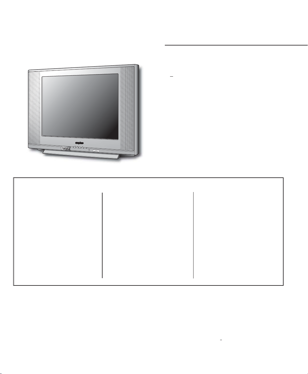
Color TV Owner’s Manual
Color TV Manual Del Propietario
Manuel d’instructions du télécouleur
“Read this manual before assembling
(or using) this product.”
Important Safety Instructions . . . . . . 2
Welcome to the World of Sanyo . . . . 3
Features . . . . . . . . . . . . . . . . . . . . . . . 3
Specifications . . . . . . . . . . . . . . . . . . . 3
Basic Set-up and Connections . . . . . . 4
Front & Rear Panels . . . . . . . . . . . . . 5
Using the Component Video and Audio
Input Jacks . . . . . . . . . . . . . . . . . . . . 6
Using the Front A/V Input Jacks . . . . 7
Using the Rear A/ V Input Jacks . . . . 8
Using the Remote Control . . . . . 9 ~ 10
TV Adjustment and Setup
How to Operate the
On-Screen Menu . . . . . . . . . . . . . . 10
Audio Mode . . . . . . . . . . . . . . . . . 11
Adjusting Picture/Sound . . . . . . . . 11
Adding or Deleting a Channel . . . . 12
Closed-Captioning . . . . . . . . . . . . . . 12
V-Guide Operation
(Parental Control) . . . . . . . . . . 13 ~ 14
Care and Cleaning . . . . . . . . . . . . . . 14
Helpful Hints (problems/solutions) . 15
Warranty (Mexico) . . . . . . . . . . . . . . 16
Warranty (U.S.A. and Canada) . . . . . 17
Child Safety Matters . . . . . . Back Cover
ESPAÑOL . . . . . . . . . . . . . . 18 ~ 35
Contenido . . . . . . . . . . . . . . . . . . . 18
FRANÇAIS . . . . . . . . . . . . . . 36 ~ 51
Table des matières . . . . . . . . . . . . 36
CONTENTS
DS20425
Printed in U.S.A. SMC, March 2005
Impreso en U.S.A. SMC, Marzo 2005
Imprimé aux é.-U. SMC, mars 2005
Part No. / No. de Parte/
N
o
de pièce : 1JC6P1P0200A–
Service Code/Código de Servicio/
Code de service : 610 319 8576
Importado Por :
Comercializadora México
Americana, S. DE R.L. DE C.V.
Nextengo Nº 78
Col. Santa Cruz Acayucan
Del. Azcapotzalco, México D.F. C.P.
02770, RFC CMA 9109119L0
Telefono: 55-5328-3500
Positioning the appliance
1. Do not place your appliance on an unstable cart, stand, shelf or table.
Serious injury to an individual, and damage to the appliance, may result
if it should fall. Your salesperson can recommend approved
carts and stands or shelf and wall mounting instructions. An
appliance and cart combination should be moved with care.
Quick stops, excessive force, and uneven surfaces may
cause the appliance and cart combination to overturn.
2. Slots and openings in the cabinet and in the back or bottom are
provided for ventilation. To ensure reliable operation of the appliance and
to protect it from overheating, these openings must not be blocked or
covered. The openings should never be covered with a cloth or other
material, and the bottom openings should not be blocked by placing the
unit on a bed, sofa, rug, or other similar surface. This appliance should
never be placed near or over a radiator or heat register. This appliance
should not be placed in a built-in installation such as a bookcase unless
proper ventilation is provided.
3. Do not expose the appliance to rain or use near water . . . for example,
near a bathtub, swimming pool, kitchen sink, in a wet basement, etc.
Hooking Up Outdoor Antenna
LIGHTNING PROTECTION FOR YOUR ANTENNA AND SET AS PER NATIONAL
ELECTRICAL CODE INSTRUCTIONS.
4. If an outside antenna is connected to the receiver, be sure the antenna
system is grounded so as to provide some protection against voltage
surges and built up static charges. Article 810 of the National Electrical
Code, ANSI/NFPA 70, provides information with respect to proper
grounding of the mast and supporting structure, grounding of the lead in
wire to an antenna discharge unit, size of grounding conductors,
location of antenna discharge unit, connection to grounding electrodes,
and requirements for the grounding electrode.
An outside antenna system should not be located in the vicinity of overhead power lines or other electric light or power circuits, or where it can
fall into such power lines or circuits. When installing an outside antenna
system extreme care should be taken to keep from touching such power
lines or circuits as contact with them might be fatal.
Plug in the power cord
5. This product should be operated only from the type of power source indicated on the marking label. If you are not sure of the type of power
supply to your home, consult your product dealer or local power
company. This product is equipped with a polarized alternating current
line plug (a plug having one blade wider than the other). This plug will fit
into the power outlet only one way. This is a safety feature. If you are
unable to insert the plug fully into the outlet, try reversing the plug. If the
plug should still fail to fit, contact your electrician to replace your
obsolete outlet. Do not defeat the safety purpose of this polarized plug.
Do not overload wall outlets, extension cords, or integral convenience
receptacles as this can result in a risk of fire or electric shock.
6. Power-supply cords should be routed so that they are not likely to be
walked on or pinched by items placed upon or against them, paying
particular attention to cords at plugs, convenience receptacles, and the
point where they exit from the product.
Cleaning
7. Before cleaning, unplug the unit from the wall outlet. Do not apply liquid cleaners or aerosol cleaners directly to the unit. Use a dry cloth for cleaning.
Service & Repair
8. Unplug the appliance from the wall outlet and refer servicing to
qualified service personnel under the following conditions:
A. If the power cord or plug is damaged or frayed.
B. If liquid has been spilled into the appliance.
C. If the appliance has been exposed to rain or water.
D. If the appliance has been dropped or the cabinet has been damaged.
E. If the appliance exhibits a distinct change in performance.
F. If the appliance does not operate normally by following the operating
instructions, adjust only those controls that are covered in the
operating instructions. Improper adjustment of other controls may
result in damage and will often require extensive work by a qualified
technician to restore the appliance to normal operation.
9. Upon completion of any service or repair, request the service technician’s
assurance that only Factory Authorized Replacement Parts that have the
same characteristics as the original parts were used, and that routine
safety checks have been performed to determine that the
appliance is in safe operating condition. Unauthorized substitutions may
result in fire, electrical shock, or other hazards.
10. Never add accessories that have not been specifically designed for use
with this appliance as they may cause hazards.
11. For added protection during a lightning storm, or when the set is left
unattended and unused for long periods of time, unplug it from the wall
outlet and disconnect the antenna. This will prevent damage to the set
due to lightning or power line surges.
12. Never push objects of any kind into this product through openings as
they may touch dangerous voltage points or short-out parts that could
result in a fire or electric shock. Never spill liquid of any kind on the
product.
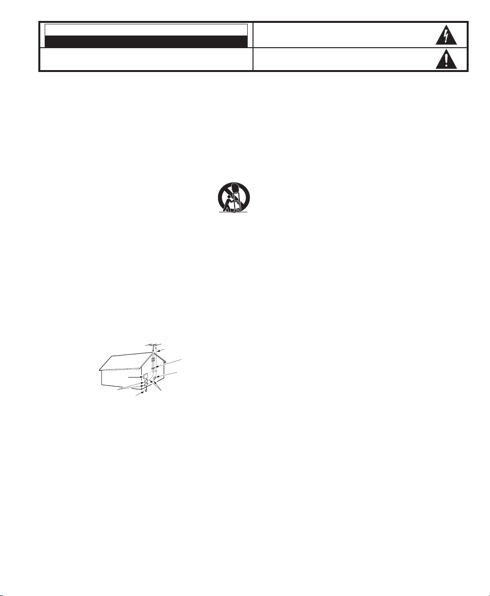
EXAMPLE OF ANTENNA GROUNDING ACCORDING TO NATIONAL
ELECTRICAL CODE, ANSI/NFPA 70
CAUTION
RISK OF ELECTRIC SHOCK DO NOT OPEN
CAUTION: TO REDUCE THE RISK OF ELECTRIC SHOCK, DO NOT REMOVE COVER (OR
BACK). NO USER-SERVICEABLE PARTS INSIDE. REFER SERVICING TO QUALIFIED
SERVICE PERSONNEL.
THIS SYMBOL INDICATES THAT DANGEROUS VOLTAGE CONSTITUTING
A RISK OF ELECTRIC SHOCK IS PRESENT WITHIN THIS UNIT.
THIS SYMBOL INDICATES THAT THERE ARE IMPORTANT OPERATING
AND MAINTENANCE INSTRUCTIONS IN THE LITERATURE ACCOMPANYING THIS UNIT.
WARNING: TO REDUCE THE RISK OF FIRE OR ELECTRIC SHOCK, DO NOT EXPOSE THIS
APPLIANCE TO RAIN OR MOISTURE.
IMPORTANT SAFETY INSTRUCTIONS
CAUTION: PLEASE ADHERE TO ALL WARNINGS ON THE PRODUCT AND IN THE OPERATING INSTRUCTIONS. BEFORE
OPERATING THE PRODUCT, PLEASE READ ALL OF THE SAFETY AND OPERATING INSTRUCTIONS. RETAIN THIS
LITERATURE FOR REFERENCE.
Follow all instructions...
“Note to CATV system installer:
This reminder is provided to call the CATV system installer’s attention to Article 820-40
of the NEC that provides guidelines for proper grounding and, in particular, specifies that
the cable ground shall be connected to the grounding system of the building, as close to
the point of cable entry as practical.”
NEC
- NATIONAL ELECTRICAL CODE
ANTENNA
LEAD IN
WIRE
GROUNDING CONDUCTORS
(NEC SECTION 810-21)
GROUND CLAMPS
ANTENNA
DISCHARGE UNIT
(NEC SECTION 810-20)
GROUND
CLAMP
ELECTRIC
SERVICE
EQUIPMENT
POWER SERVICE GROUNDING
ELECTRODE SYSTEM
(NEC ART 250, PART H)
2
Need help?
Visit our Web site at www.sanyoctv.com or Call 1-800-877-5032
Trilingual On-Screen Menu
Automatic Channel Search
Auto Shut Off
Closed-Captioning/Quikcap
Digital picture controls with
on-screen display
MTS stereo/SAP Decoder
Auto Flesh Tone
Factory preset adjustments for
picture/sound
Front Surround Sound
Tone
V-Guide (Parental Control)
Game Mode
480i Component AV Input Jacks
Audio/Video In Jacks
2 sets—Front (AV1), Rear (AV2)
S-Video In Jack
Sleep Timer (3 hours)
TV Reset
181 Channel Tuning System
VHF Channels 2-13
UHF Channels 14-69
Cable TV (CATV) 1, 14-125
Automatic Fine Tuning
VHF and Cable Channels
24-Remote Control
0~9 Numbered Channel Selection
Channel Scanning
Volume Mute
Power Recall
Display Sleep
Caption Reset
Menu V-Guide
Input
PICTURE TUBE SIZE, True Flat Screen
(Measured Diagonally) . . . . . . . . . . . . . . . . . . . . . . . . . 20-inches
PICTURE RESOLUTION . . . . . . . . . . . . . . . . . . . . . . . . 260 Lines
Video Input . . . . . . . . . . . . . . . . . . . . . . . . . . . . . . . . . . . . 400 Lines
ANTENNA INPUT . . . . . . . . . . . . . . . . . UHF/VHF/CATV 75Ω
POWER REQUIREMENT . . . . . . . . . . . . . . . . . . . . . 120VAC 60Hz
POWER . . . . . . . . . . . . . . . . . . . . . . . . . . . . . . . . . . . . . . 65 watts
HORIZONTAL DIM. (Width) . . . . . . . . . . . . . . . . 23.1 in. (588mm)
VERTICAL DIM. (Height) . . . . . . . . . . . . . . . . . 17.8 in. (453mm)
DEPTH DIM. (Thickness) . . . . . . . . . . . . . . . . . 18.8 in. (478mm)
WEIGHT (Approx.) . . . . . . . . . . . . . . . . . . . . 53.5 lbs. (24.3 Kg.)
SOUND (2 Speakers) . . . . . . . . . . . . . . . . . . . . . . . Size: 5x9 cm
AMPLIFIER . . . . . . . . . . . . . . . . . . . . . . . . . . Built-in with 1W/ch
AUDIO/VIDEO INPUT JACKS . . . . . . . . . . . . . . . . . . . . . Video Input
. . . . . . . . . . . . . . . . . . . . Audio Input (2 sets, R/L – Front/Rear)
. . . . . . . . . . . . . . . . . . . . . . . . . . . . . . . . . . . . . . . .S-Video Input
480i COMPONENT VIDEO
INPUT JACKS . . . . . . Component Video Inputs (Y, Pb, Pr – R/L)
CAUTION: FCC Regulations state that improper modifica-
tions or unauthorized changes to this unit may
void the user’s authority to operate the unit.
Welcome to the World of Sanyo
Thank you for purchasing a Sanyo Color Television. You made an excellent choice for Performance, Styling,
Reliability, and Value. The TV is designed with easy to use on-screen set-up instructions and operating features.
Please retain this owner’s manual for future reference. Need assistance? Visit our Web site at
www.sanyoctv.com or call toll free 1-800-877-5032.
FEATURES
SPECIFICATIONS
3
Need help?
Visit our Web site at www.sanyoctv.com or Call 1-800-877-5032
This symbol on the nameplate means the product is Listed by Underwriters’ Laboratories Inc.
It is designed and manufactured to meet rigid U.L. safety standards against risk of fire,
casualty and electrical hazards.
CATV FRANCHISE NOTE:
Cable companies, like public
utilities, are franchised by
local government authorities.
To receive cable programs,
even with equipment which
is capable of receiving cable
channels, the consumer
must subscribe to the cable
company’s service.
AUDIO VIDEO
INPUT 2
R
L
UHF/VHF/CATV
75Ω
P
R
P
B
Y
VIDEO
(MONO)
S-VIDEO
COMPONENT
2
IN
FROM ANT.
OUT
OUT TO TV
CATV IN
OUT TO TV
S-VIDEO
CH3
CH4
VIDEO
L-AUDIO-R
VIDEO
L-AUDIO-R
IN FROM
SAT.
IN OUT
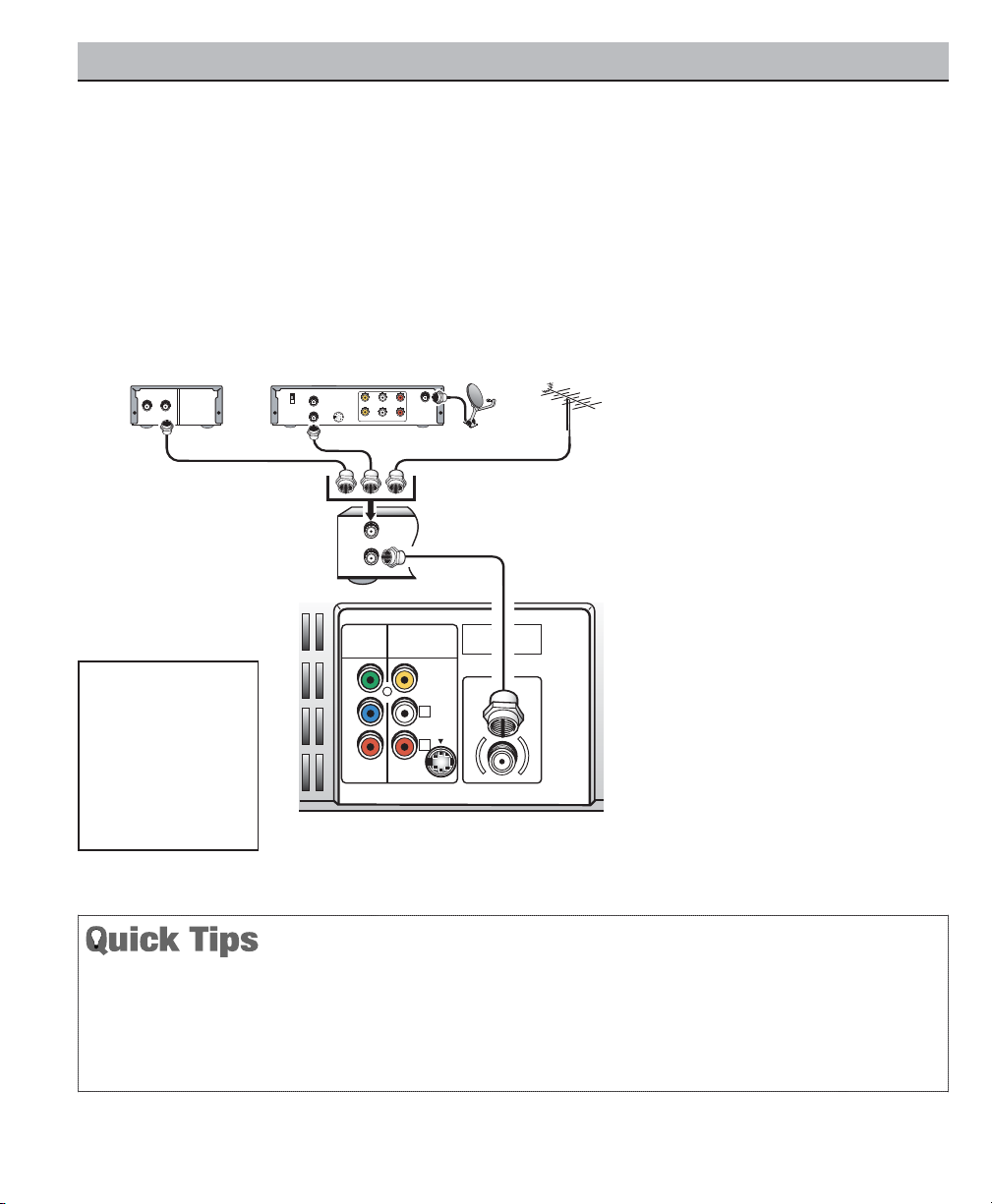
CONNECTING CABLE SERVICE, OR RF ANTENNA, OR SATELLITE DISH
RECEIVER TO TV
Cable Box
RF Antenna
Satellite Receiver
TV Back
INITIAL SET-UP
1.
Install batteries in remote control,
see page 9.
2.
Connect signal, see below.
3.
Plug in AC power cord.
4.
Press POWER key to turn on TV.
5. Follow on-screen instructions, see
pages 10 ~ 12.
VCR Back
Operational Tip for No Signal
Connection:
If the TV is used as a monitor only, with a
DVD player or some other type of external
equipment, and no cable or antenna signal
is available, the following setup is
necessary:
– Your TV is designed to automatically
search for available channels. Therefore,
the initial start up requires that you press
the MENU key, enabling the TV to automatically go through the channel search
process before you can operate the TV.
After the initial channel search is completed, you must press the MENU key
again to complete the channel search
process. This may take several minutes.
– After the channel search process is com-
plete (2 searches), you can press the
INPUT key on the remote control to use
the TV as a monitor.
Notes:
– If you do not have a
cable box, connect
cable directly to TV
75 ohm jack or VCR.
– If you do not have a
VCR, connect signal
directly to TV 75 ohm
jack.
BASIC SET-UP AND CONNECTIONS
The TV will automatically select the correct Antenna
mode for the type of RF signal you connect.
TV will switch off automatically after 15 minutes if there
is no signal reception (cable out or station not broadcasting).
Exception—When the Video mode is selected, the TV will
not automatically switch off when signal reception has
stopped for 15 minutes.
If you move the TV to a new location, press the RESET
key twice after connecting the signal and turning on the
TV.
4
Need help?
Visit our Web site at www.sanyoctv.com or Call 1-800-877-5032
AUDIO VIDEO
INPUT 2
R
L
UHF/VHF/CATV
75Ω
P
R
P
B
Y
VIDEO
(MONO)
S-VIDEO
COMPONENT
2
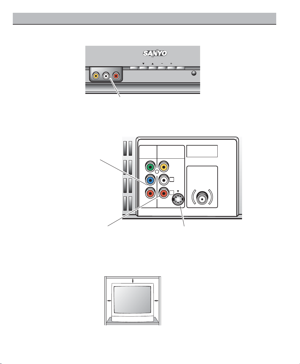
POSITIONING THE TV
Do not position the TV in a confined
area. Allow space for normal air
circulation around electronic parts.
Audio Video Input 2 Jacks (AV2)
Connect video equipment here (see pages 6 and 8).
Note: S-Video connection will override an AV2
video connection.
S-Video In Terminal
To enhance video detail use the AV2
S-Video jack instead of the AV2 Video jack,
if available on your external equipment. (An
S-Video connection will override connection to
the AV2 video input jack. See page 8.)
480i Component Video In Jacks
(Component 2: Y, Pb, Pr)
Connect video equipment here
(see page 6).
Note: Audio Video Input (AV2) and
Component inputs share the
same audio (R/L) input jacks.
MENU CH VOL POWER
VIDEO IN L- AUDIO -R
Audio Video In Jacks (AV1)
Connect video equipment here (see page 7).
FRONT
BACK
FRONT AND REAR PANELS
5
Need help?
Visit our Web site at www.sanyoctv.com or Call 1-800-877-5032
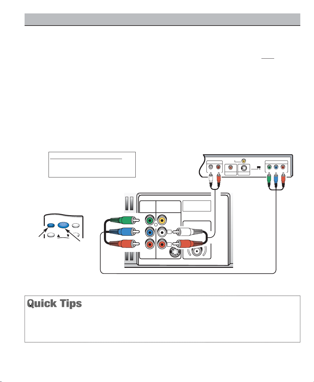
CONNECTING A DVD PLAYER
Switch off TV and external equipment before connecting
cables. (Cables are not supplied.)
Connect a DVD Player or other equipment’s interlaced
Component Video Out to the TV Component Video In
(Y-Pb-Pr) Jacks.
Connect the DVD Player’s Audio Out to the TVAV2
Audio In (L/R) Jacks.
Press POWER to turn on the TV. Turn on external
equipment also.
To access Audio Video inputs, press the INPUT key to
select COMPONENT2.
Notes: DVD Player component output must be set to
Interlaced (480i).
Audio/ Video Input 2 (AV2) and Component inputs
share the same audio (R/L) input jacks.
Connect equipment to the Component2 video
input or the AV2 video input, but not both types at
the same time.
Y
P
B
/CB/C
R
P
R
COMPONENT VIDEO OUT
AUDIO OUT
RL
DIGITAL OUT
COAXIAL
S-VIDEO OUT
VIDEO OUT
VIDEO OUT
SELECT
S-VIDEO COMPONENT
AUDIO VIDEO
INPUT 2
R
L
UHF/VHF/CATV
75Ω
P
R
P
B
Y
VIDEO
COMPONENT
2
S-VIDEO
DVD Player
TV Back
What you will need for connections:
Component video cable – 1
Audio Cable – 1
MENU RECALL
RESETINPUT
CH
POWER
Remote Control
USING THE COMPONENT VIDEO AND AUDIO INPUT JACKS
6
Need help?
Visit our Web site at www.sanyoctv.com or Call 1-800-877-5032
A solid Blue screen with COMPONENT2 displayed
means that the Video mode is selected, but no signal
is being detected at the Component jacks. Check connection, and turn on external equipment.
Press INPUT key after connecting cables to access
the A/V inputs. There is NO need to tune to a blank
channel.
 Loading...