

Sanus VXF730 Instruction Manual
GET IT
RIGHT
THE FIRST TIME
Follow this step-by-step
VXF730-B2
INSTRUCTION MANUAL
WE’RE HERE TO HELP
Want to watch a video that
shows how easy this DIY
project will be?
Watch it now at:
SANUS.com/2816
instruction manual to
speed up your installation.
Get it right the first time.
HeightFinder™ shows you
where to drill.
Check it out at:
SANUS.com/2567
Our install experts are
standing by to help.
Call us at:
US: 800-359-5520
EMEA: +31 (0) 495 580 852
UK: 0800 056 2853
AUS: +61 (0) 7 3299 7000
Texto en español, página 12 Deutscher Text Seiten 16 Svensk text sida 20
Texte français page 14 Nederlandse tekst op pagina 18
Русский текст: стр. 22
中文文字说明请参见第 24 页
日本語は 26 ページ

IMPORTANT SAFETY INSTRUCTIONS
PLEASE READ ENTIRE MANUAL PRIOR TO USE – SAVE THESE INSTRUCTIONS
Please read through these instructions completely to be sure you’re comfortable with this easy install process.
Check your TV owner’s manual to see if there are any special requirements for mounting your TV.
If you do not understand these instructions or have doubts about the safety of the installation, assembly or use of this product,
contact Customer Service.
CAUTION: Avoid potential personal injuries and property damage!
● This product is designed ONLY to be installed into wood studs, solid concrete or concrete block.
— DO NOT INSTALL INTO DRYWALL ALONE — DRYWALL ALONE WILL NOT HOLD THE WEIGHT OF YOUR TV.
● This product is designed for INDOOR USE ONLY.
● The wall must be capable of supporting five times the weight of the TV and mount combined.
● Do not use this product for any purpose not explicitly specified by manufacturer.
● Manufacturer is not responsible for damage or injury caused by incorrect assembly or use.
TV Weight Limit
(including accessories)
DO NOT EXCEED
Wall
Construction
ONLY install on
these acceptable
wall types.
Unsure
Call Customer Service
175 lbs.
(79.3 kg)
CAUTION:
DO NOT install
in drywall alone
Drywall alone
NOT hold
will
the weight of
your TV.
If your TV, plus accessories, weighs MORE
than indicated, this mount is NOT compatible.
Visit SANUS.com or call customer service to
find a compatible mount.
wood studs Solid concrete or
concrete block
ACCEPTABLE ACCEPTABLE
Tools
Needed
2
Measure
Wood Stud
Pencil Level Tape
Install
Stud
Finder
Awl
7/32 in.
(5.5 mm)
Wood
Drill Bit
1/2 in.
(13 mm)
ScrewdriverTape
Install
Concrete
Electric
Drill
3/8 in.
(10 mm)
Concrete
Drill Bit
Socket
Wrench
Hammer
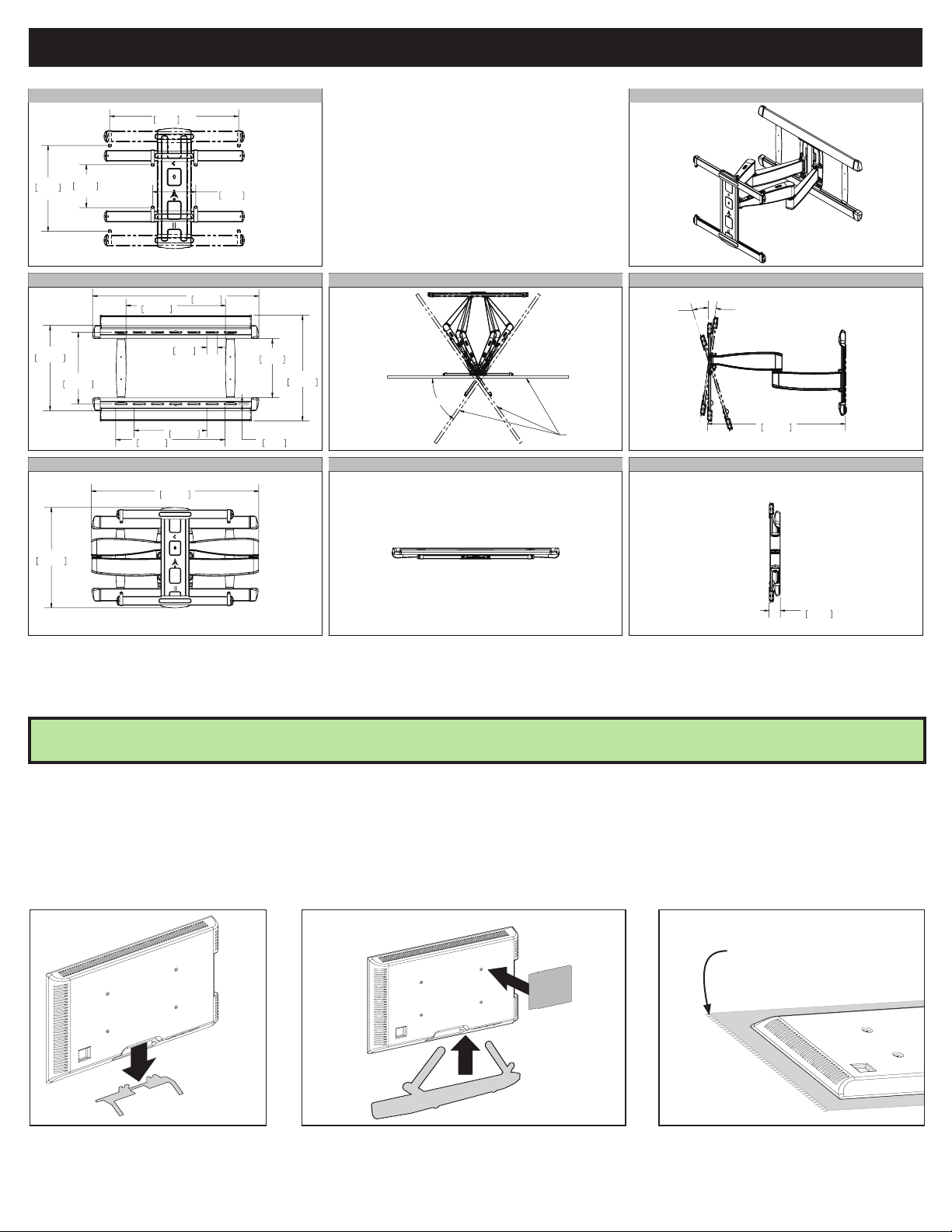
DIMENSIONS IN. [MM]
TV INTERFACE
3-D
23.62in
MAX
600mm
7.87in
200mm
MIN
7.87in
200mm
MIN
15.75in
400mm
MAX
476.2mm
559.6mm
18.75in
22.03in
15.76in
400.4mm
WALL PLATE
609.6mm
36.53in
927.7mm
21.83in
554.6mm
2.36in
60mm
16.00in
406.4mm
24.00in
FULLY ASSEMBLED MOUNT
36.77in
934.1mm
12.95in
329mm
0.36in
9.1mm
590.8mm
23.26in
TOP VIEW - EXTENDED
55deg
SIMULATED 75"
FLAT SCREEN TV
15deg DOWN
TOP VIEW - RETRACTED
SIDE VIEW - EXTENDED
5deg UP
30.31in
769.9mm
SIDE VIEW RETRACTED
2.45in
62.3mm
BEFORE YOU BEGIN
Remove the stand from
your TV — if attached.
Legrand AV Inc. and its aliated corporations and subsidiaries (collectively, “Legrand ”), intend to make this manual accurate and complete. However, Legrand makes no claim that the information
contained herein covers all details, conditions, or variations. Nor does it provide for every possible contingency in connection with the installation or use of this product. The information contained in this
document is subject to change without notice or obligation of any kind. Legrand makes no representation of warranty, expressed or implied, regarding the information contained herein. Legrand assumes
no responsibility for accuracy, completeness or suciency of the information contained in this document.
Install any accessories you may
have purchased, if they requireTV removal
prior to assembly. Note that the TV is
removable for future accessory purchases.
Protect the face of your TV
when laying it down for installation.
Soft clean surface
3
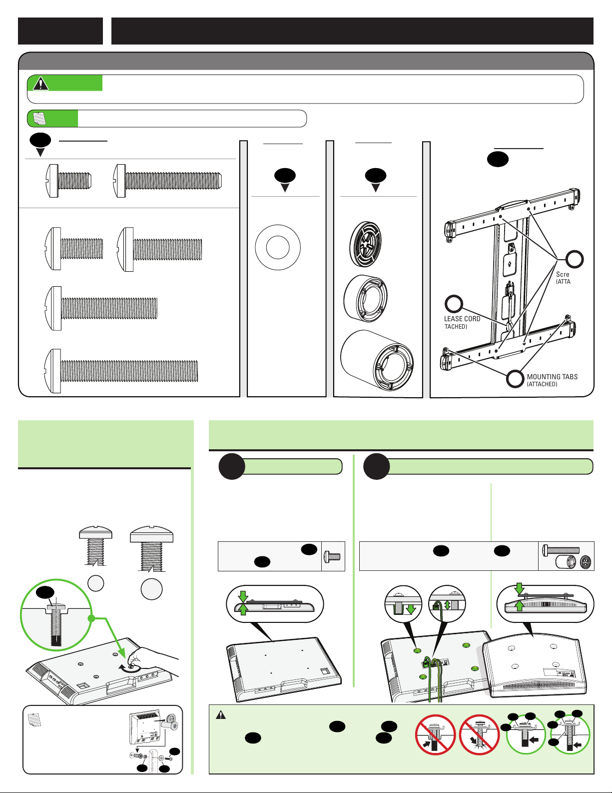
ATTACH TV BRACKET TO TVSTEP 1
M8 x 35mm
22mm
M6 x 12mm
M6 x 35mm
M8 x 50mm
2.5mm
5mm
M8 x 25mm
M8 x 16mm
Parts and Hardware for STEP 1
WARNING: This product contains small items that could be a choking hazard if swallowed. Before starting assembly, verify all parts are included
and undamaged. If any parts are missing or damaged, do not return the damaged item to your dealer; contact Customer Service. Never use damaged parts!
NOTE: Not all hardware included will be used.
M6
M8
01
TV Screws
(qty. 4 each)
[Only one size fits your TV]
Washers
(qty. 4 each)
M6/M8 M6/M8
Spacers
[If necessary]
(qty. 4 each)
0302
R
RELEASE CORD
(ATTACHED)
TV Bracket
(qty. 1)
04
B
Screws
(ATTACHED)
1.1 Select TV
Screw Diameter
Only one screw size fits your TV.
01
M6
M8
1.2 Select TV Screw Length / Spacers
NO SPACER SPACER NEEDED
A B
• Flat Back TV
[TV brackets
lay flat on your TV]
Use short TV screws
Spacers
not needed.
03
01
.
• Flat Back TV with
Extra Space Needed
[for deep inset holes
or cable interference]
Use long TV screws 01 and spacers
create extra space between the TV and TV bracket.
Inset Holes Cables Rounded Back
MOUNTING TABS
M
(ATTACHED)
• Rounded or
Irregular Back TV
[TV brackets NOT
resting flat on your TV]
03
to
NOTE: If your TV
included inset spacers or
adapters, use them UNDER
the mount hardware.
4
CAUTION: Verify adequate thread
engagement with your screw 01, washer 02,
spacer 03 combination AND TV bracket 04.
01
03
02
— Too short will not hold your TV.
— Too long will damage your TV.
Too Short Too Long Correct
01
02
04
01
02
04
03
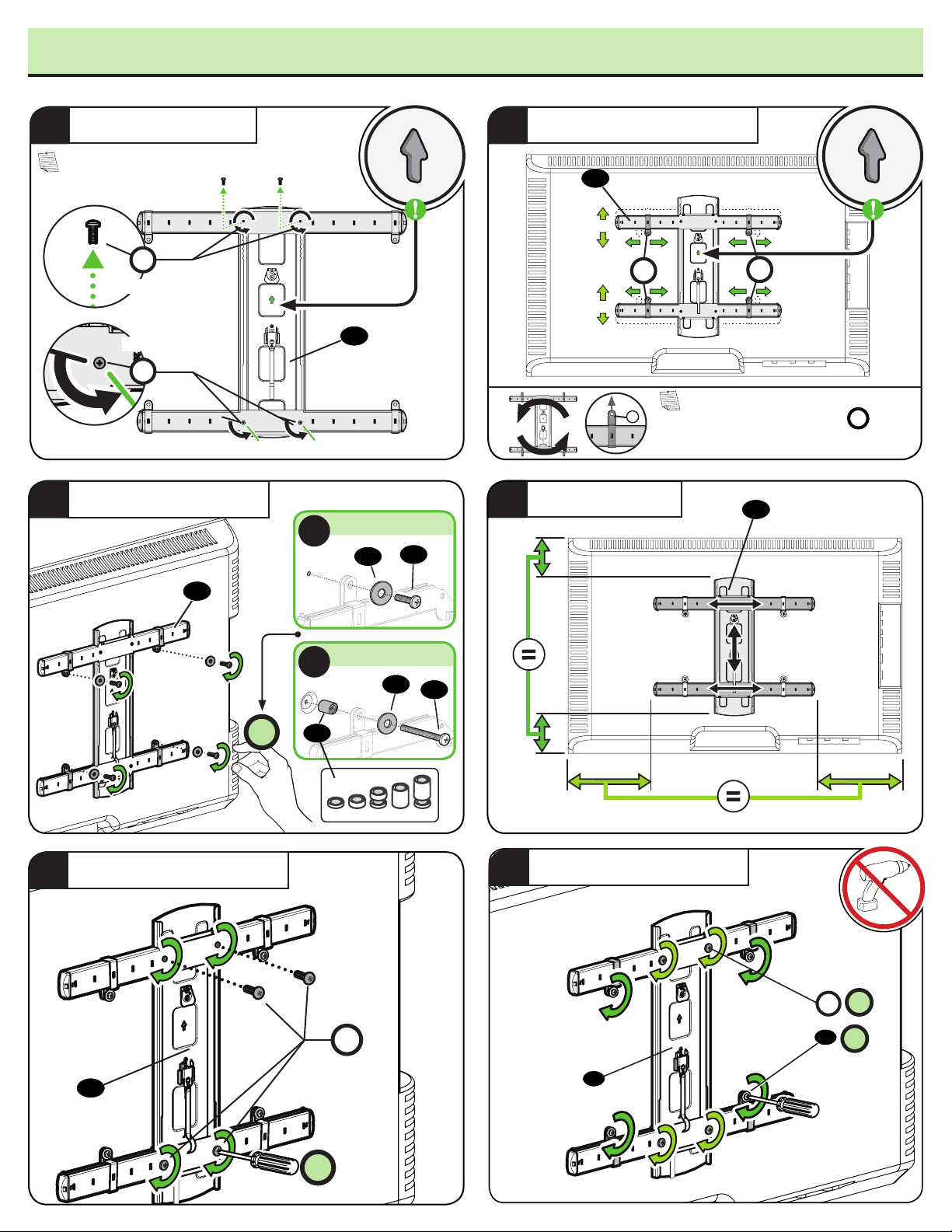
1.3 Attach TV Bracket Assembly to TV
PREP TV BRACKET
1
NOTE: 400 x 400 hole patterns can skip to 3 below.
B
REMOVE
LOOSEN
B
LOOSELY ASSEMBLE
3
NO SPACER
A
04
02
01
ALIGN WITH TV HOLES
2
04
M
M
The horizontal arms (and tabs
can be reversed top/bottom, if neeeded
to fit non-standard hole patterns.
CENTER ON TV
4
NOTE:
04
M
M
)
SECURE TV BRACKET
5
04
4X
SPACER NEEDED
B
03
B
02
01
TIGHTEN ALL SCREWS
6
4X
B
01
4X
04
04
4X
5
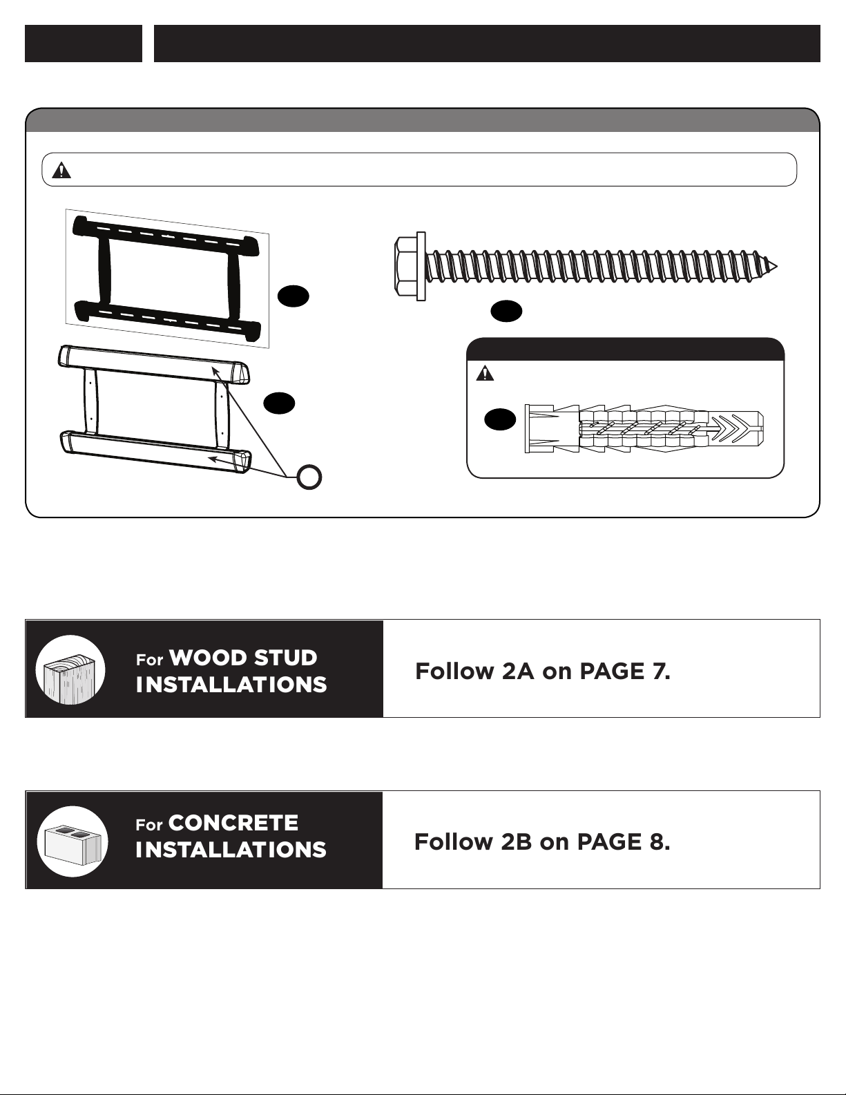
STEP 2
ATTACH WALL PLATE TO WALL
Parts and Hardware for STEP 2
Before starting assembly, verify all parts are included and undamaged. If any parts are missing or damaged, do not return the damaged item to your dealer;
contact Customer Service. Never use damaged parts!
Lag Bolt
Wall Plate
Template
05
(qty. 1)
5/16 in. x 3½ in.
(qty. 5)
07
For concrete installations ONLY
Wall Plate
(qty. 1)
06
P
For WOOD STUD
INSTALLATIONS
Cover Plate
(Attached)
CAUTION: Do not use in drywall or wood
Concrete Anchor
08
(qty. 5)
Fischer UX10 x 60R
Follow 2A on PAGE 7.
For CONCRETE
INSTALLATIONS
6
Follow 2B on PAGE 8.
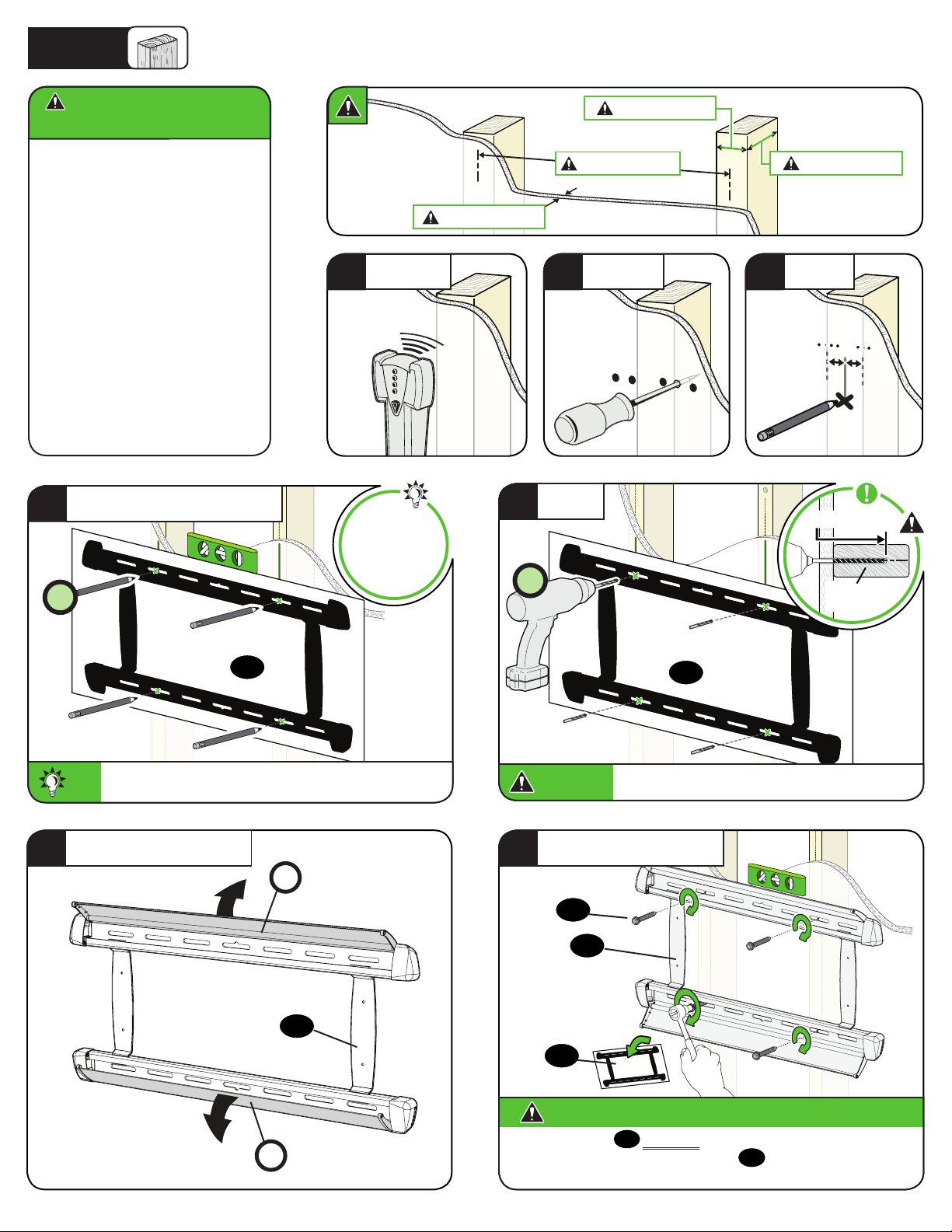
2A
Wood Stud Installation
CAUTION: Avoid potential
personal injury or property damage!
● Drywall covering the wall
must not exceed 5/8 in. (1.5 cm)
● Minimum wood stud size:
nominal 2 x 4 in. (5.1 x 10.2 cm)
actual 1 ½ x 3 ½ in. (3.8 x 8.9 cm)
● Minimum horizontal space
between fasteners:16 in. (40.6 cm)
● Stud centers must be verified
POSITION TEMPLATE
4
4X
LOCATE
1
Visit
HeightFinder™
sanus.com
/2567
Max. 5/8 in. (1.5 cm)
5
4X
Min. 16 in. (40.6 cm)
VERIFY
2
DRILL
Min. 1 ½ in. (3.8 cm)
3
MARK
Min. 3 ½ in. (8.9 cm)
2 ¾ in. (6.9 cm)
7/32 in.
(5.5 mm)
To calculate your precise wall plate location, check out
TIP:
our HeightFinder at sanus.com [www.sanus.com/2567].
OPEN COVERS
6
05
05
CAUTION:
SECURELY TIGHTEN
7
Be sure you drill into the CENTER of the stud.
P
07
06
06
05
CAUTION: Avoid potential personal injury or property damage!
P
All four lag bolts
unwanted movement of the wall plate
securely fastened to the wall before continuing on to the next step.
MUST BE firmly tightened to prevent
07
Ensure the wall plate is
06
.
Skip to STEP 3 on PAGE 9.
7
12 in.
(30 cm)
24 in.
(61cm)
12 in.
(30 cm)
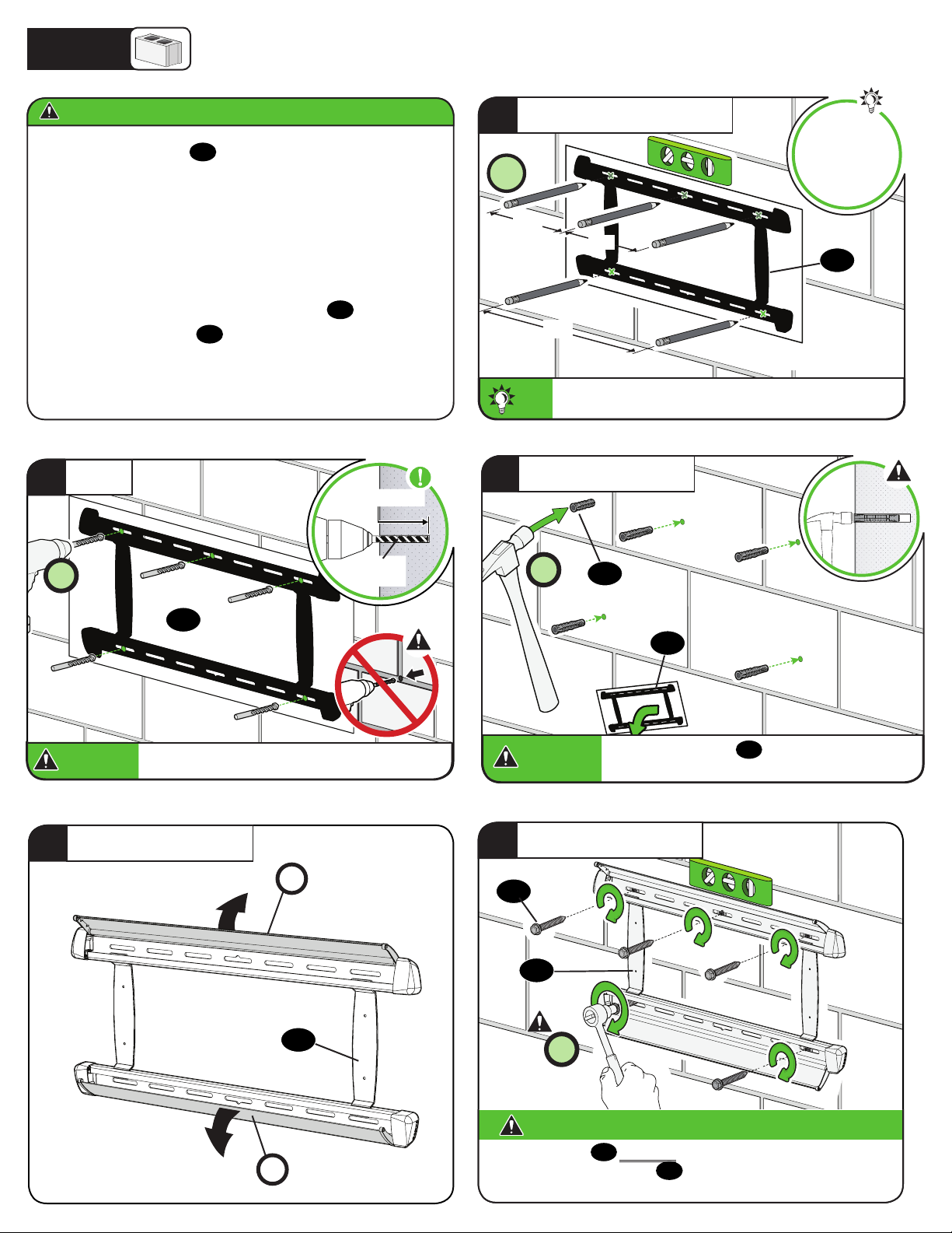
2B
Solid Concrete or Concrete Block Installation
CAUTION: Avoid potential personal injury or property damage!
● Mount the wall plate 06 directly onto the concrete surface
● Minimum solid concrete thickness: 8 in. (20.3 cm)
● Minimum concrete block size: 8 x 8 x 16 in. (20.3 x 20.3 x 40.6 cm)
● Minimum horizontal space between fasteners:
TOP RAIL: 12 in. (30.5 cm)
BOTTOM RAIL: 24 in. (61.0 cm)
● FOR CONCRETE APPLICATIONS, TV bracket 09 must remain
centered in wall plate 06. Keep this in mind when selecting
the wall plate location
DRILL
2
5X
3 in. (7.6 cm)
3/8 in.
(10 mm)
POSITION TEMPLATE
1
5X
To calculate your precise wall plate location, check out
TIP:
TIP:
our HeightFinder at sanus.com [www.sanus.com/2567].
INSERT ANCHORS
33
5X
08
Visit
HeightFinder™
sanus.com
/2567
05
CAUTION:
CAUTION:
OPEN COVERS
4
05
Never drill into the mortar between blocks.
Never drill into the mortar between blocks.
P
06
CAUTION:
CAUTION:
SECURELY TIGHTEN
5
Be sure the anchors
the concrete surface.
07
06
5X
05
14
08
are seated flush with
P
8
CAUTION: Avoid potential personal injury or property damage!
All five lag bolts
movement of the wall plate
fastened to the wall before continuing on to the next step.
MUST BE firmly tightened to prevent unwanted
07
06
Ensure the wall plate is securely
.
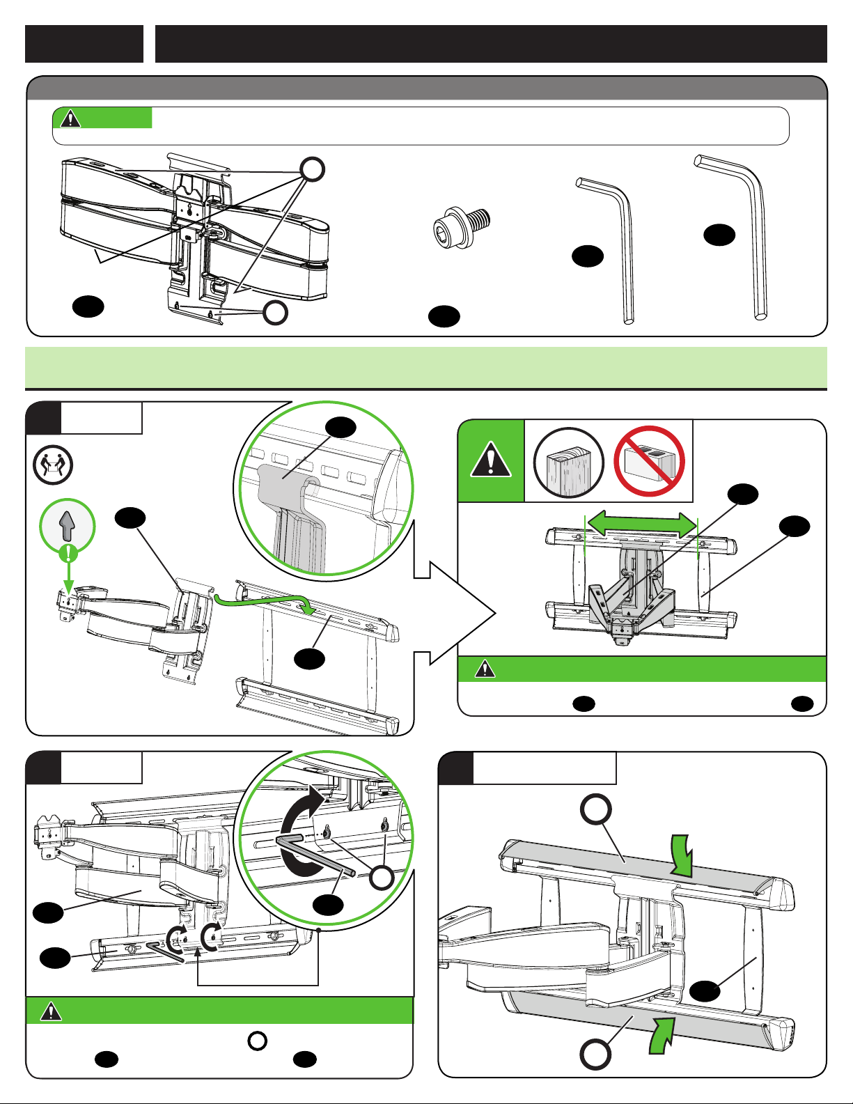
STEP 3
ATTACH TV TO WALL PLATE
Parts and Hardware for STEP 3
WARNING: This product contains small items that could be a choking hazard if swallowed. Before starting assembly, verify all parts are included
and undamaged. If any parts are missing or damaged, do not return the damaged item to your dealer; contact Customer Service. Never use damaged parts!
CABLE COVERS
C
(ATTACHED)
5/32 in.
Hex Key
12
(qty. 1)
Arm Assembly
(qty. 1)
09
LOCKING SCREWS
S
(ATTACHED)
10-32 x 3/8 in.
Securement
Screw
(qty. 1)
10
3/32 in.
Hex Key
11
(qty. 1)
3.1 Attach the Arm Assembly to the Wall Plate
HANG
1
09
2
HEAVY! You may need
assistance with this step.
09
SECURE
06
09
CAUTION: Avoid potential personal injury or property damage!
For CONCRETE APPLICATIONS:
The arm assembly
CLOSE COVERS
3
MUST remain centered in wall plate
09
P
06
06
.
S
11
11
06
CAUTION: Avoid potential personal injury or property damage!
Always make sure both locking screws
assembly
09
is securely fastened to wall plate
are tightened, so the arm
S
06
.
06
P
9
 Loading...