

Page 1
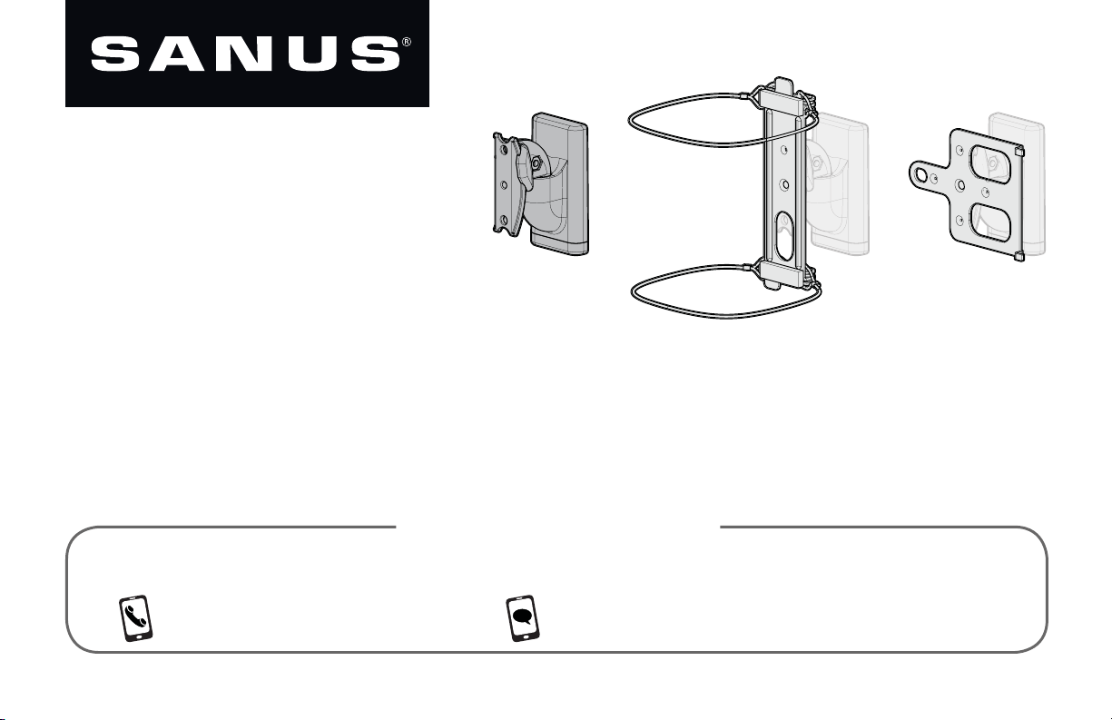
WSWM21 and WSWM
22
WIRELESS SPEAKER
WALL MOUNT
INSTRUCTION MANUAL
WE’RE HERE TO HELP
If you have any questions along the way, our US-based install experts are standing by to help.
Call us at: 800-359-5520 Or, chat at: SANUS.com/chatSP
Page 2
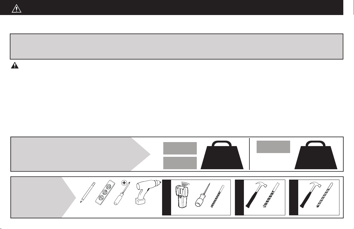
CAUTION: IMPORTANT SAFETY INSTRUCTIONS — PLEASE READ ENTIRE MANUAL PRIOR TO USE — SAVE THESE INSTRUCTIONS
Before getting started, let’s make sure this product is perfect for you!
This mount is designed to support Sonos
®
One™, PLAY:1™ and PLAY:3™ speakers,
as well as other wireless speakers with similar mounting holes.
CAUTION: Avoid potential personal injuries and property damage!
Check your speaker owner’s manual to see if there are any special requirements for mounting your speaker.
•
Please read through these instructions completely to be sure you’re comfortable with this easy install process.
•
Do not use this product for any purpose not explicitly specifi ed by manufacturer.
•
Manufacturer is not responsible for damage or injury caused by incorrect assembly or use.
•
The wall must be capable of supporting fi ve times the weight of the speaker and mount combined.
•
If you do not understand these instructions or have doubts about the safety of the installation, assembly or use of this product,
•
contact Customer Service at 1-800-359-5520.
Speaker Weight Limit
DO NOT EXCEED
One™
PLAY:1™
4 lbs.
(1.8 kg)
PLAY:3™
[and other
speakers]
10 lbs.
(4.5 kg)
Tools
Needed
2
Pencil Level
Screwdriver
Electric
Drill
Stud Finder
Wood Stud Install
Awl
1/8 in.
(3 mm)
Wood
Drill Bit
Concrete Install
Hammer Drill Bit
1/4 in.
(6.5 mm)
Masonry
Drywall Install
Hammer Drill Bit
1/4 in.
(6.5 mm)
Page 3
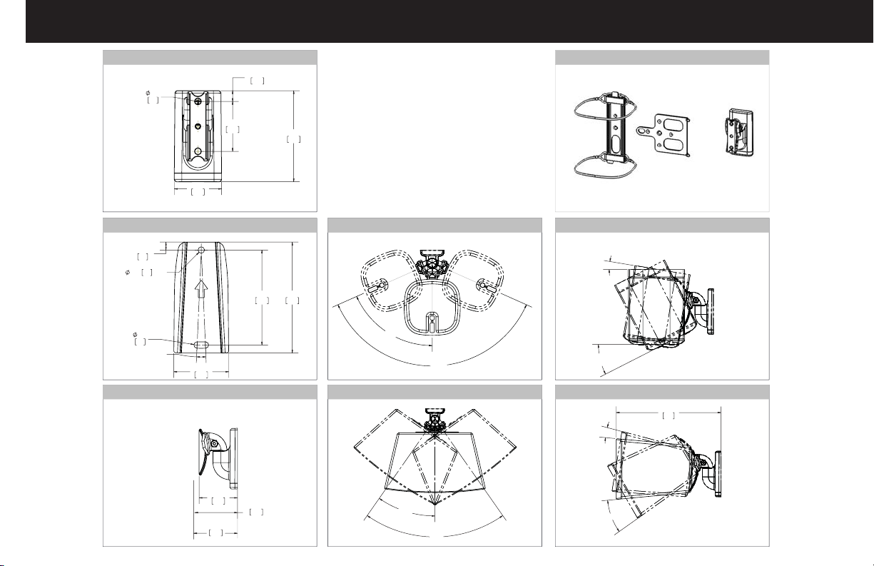
Dimensions
TV INTERFACE
0.26
2X
6.6
1.99
50.6
WALL PLATE
0.25
6.4
0.20
5.1
THRU
0.20
5.1
5.00°
1.73
44.0
FULLY ASSEMBLED MOUNT
3-D
0.45
11.5
2.10
53.3
3.83
97.2
TOP VIEW - SONOS® One™ / PLAY:1™
3.00
3.50
76.1
88.9
66°
132°
TOP VIEW - SONOS® PLAY:3
™
SIDE VIEW - SONOS® One™ / PLAY:1
9°
27° PLAY:1
18° SONOS One
SIDE VIEW - SONOS® PLAY:3
9°
™
9
224
™
2.77
70.3
PLAY 3
2.43
61.6
2.70
68.6
PLAY ONE
35°
30°
70°
3
Page 4
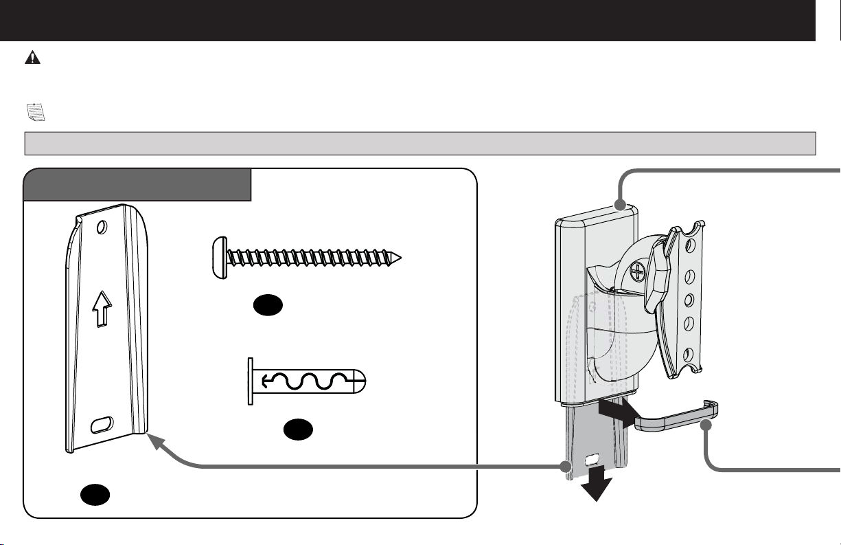
Supplied Parts and Hardware
WARNING: This product contains small items that could be a choking hazard if swallowed.
Before starting assembly, verify all parts are included and undamaged. If any parts are missing or damaged, do not return the damaged item to
your dealer; contact Customer Service. Never use damaged parts!
NOTE: Not all hardware included will be used.
Quantities shown are for one speaker mount.
STEP 1 Parts and Hardware
Wall Plate Screw
#10 x 1¾ in.
02 x2
Anchor
AF6 Toggler
a
03 x2
Wall Plate
b
01 x1
4
Page 5
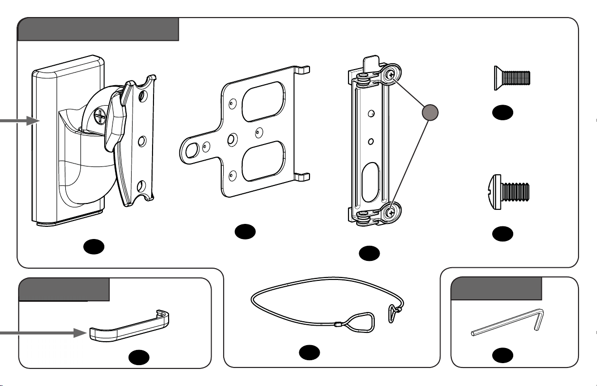
STEP 2 Parts and Hardware
Screw
(
)
Screw
(attached)
attached
S
Interface Screw
10-24 x 1/2 in.
08 x1
Speaker Screw
(and Other Wireless Speakers)
STEP 3 Part
Mount
04 x1
Cap
10 x1
Play:3™ Interface
05 x1
Sonos One™ Interface
Sonos One™ wire
07 x2
1/4-20 x 10mm
09 x1
06 x1
Adjustments
Reset Tool
11 x1
5
Page 6
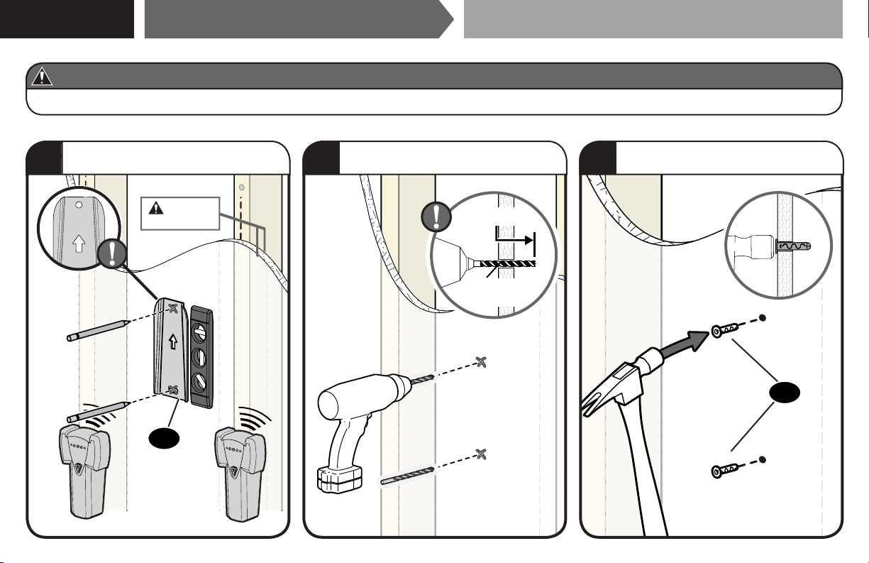
STEP 1A
CAUTION: Avoid potential personal injury or property damage!
● Drywall covering the wall, must not be less than 1/2 in. (12.7 mm)
Drywall Only InstallationAttach Wall Plate to Wall
Mark hole locations BETWEEN studs.
1
Min. 1/2 in.
UP
6
(12.7 mm)
01
Drill two holes.
2
1 in. (25 mm)
1/4 in.
(6.55 mm)
Insert two Anchors, flush with drywall.
3
03
Page 7
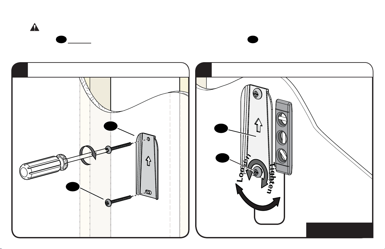
CAUTION:
Both screws
the wall before continuing on to the next step.
Avoid potential personal injury or property damage!
02
MUST BE firmly tightened to prevent unwanted movement of the wall plate
01
Ensure the wall plate is securely fastened to
.
Secure wall plate to wall.
4
02
01
Loosen lower screw for level adjustment - tighten when finished.
5
01
02
Go to STEP 2, PAGE 12.
7
Page 8
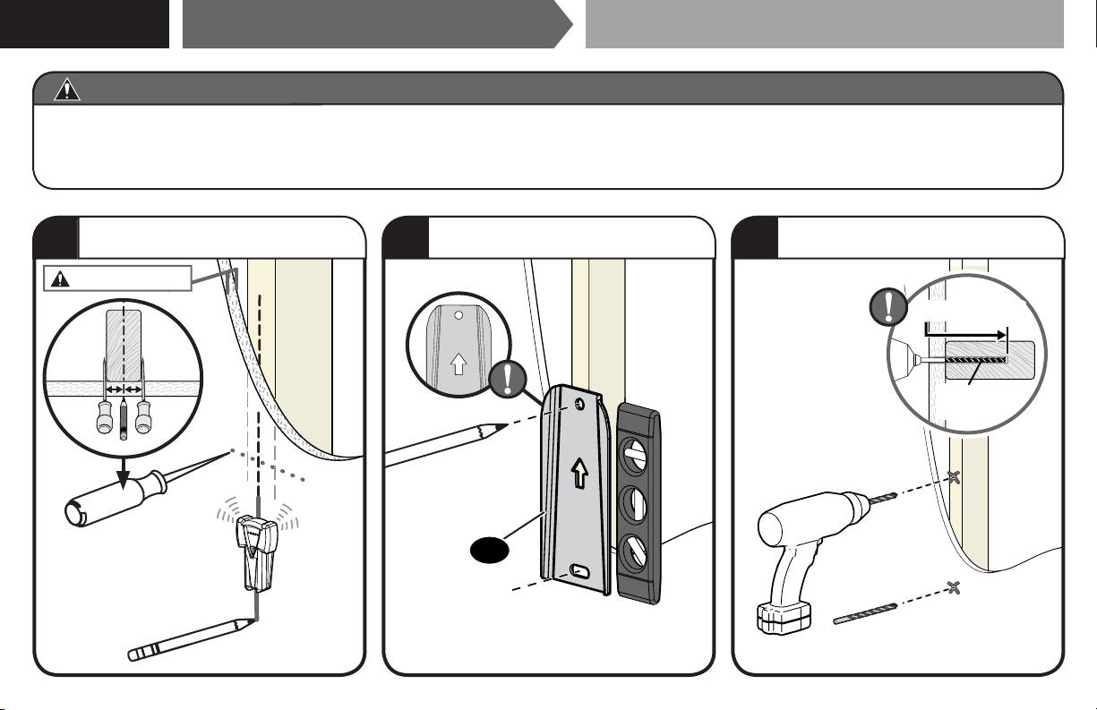
STEP 1B
CAUTION: Avoid potential personal injury or property damage!
● Drywall covering the wall, must not exceed 5/8 in. (16 mm)
● Minimum wood stud size: nominal 2 x 4 in. (51 x 102 mm) actual 1½ x 3½ in. (38 x 89 mm)
● Stud center must be verified
Wood Stud InstallationAttach Wall Plate to Wall
Locate your stud CENTER.
1
Max. 5/8 in. (16 mm)
8
Mark two hole locations.
2
UP
01
Drill two holes.
3
1 ¾ in. (45 mm)
1/8 in.
(3 mm)
Page 9
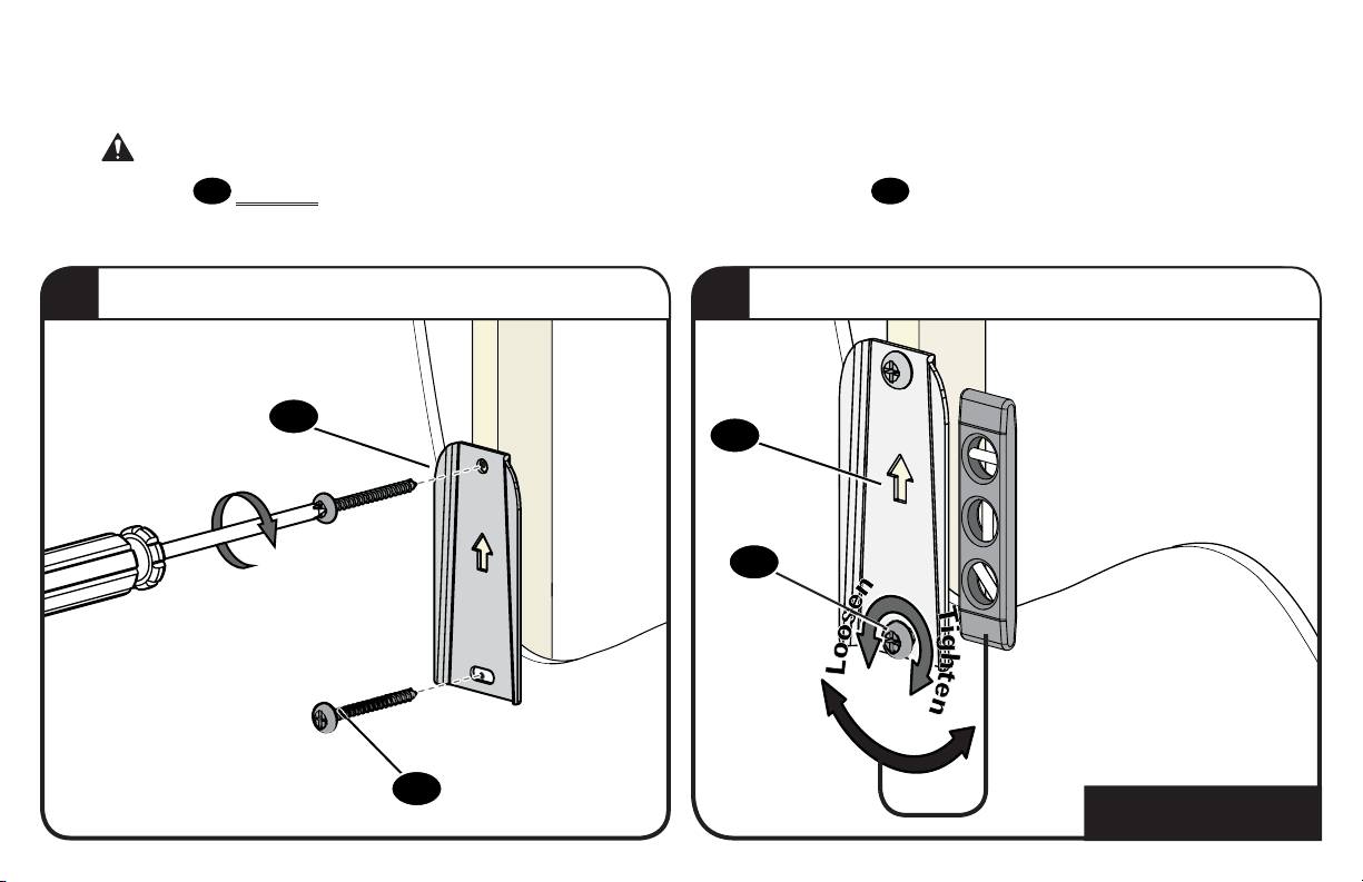
CAUTION:
Both screws
the wall before continuing on to the next step.
Avoid potential personal injury or property damage!
02
MUST BE firmly tightened to prevent unwanted movement of the wall plate
01
Ensure the wall plate is securely fastened to
.
Secure wall plate to wall.
4
01
02
Loosen lower screw for level adjustment - tighten when finished.
5
01
02
Go to STEP 2, PAGE 12.
9
Page 10
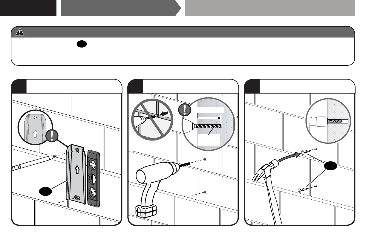
STEP 1C
CAUTION: Avoid potential personal injury or property damage!
● Mount the wall plate 01 directly onto the concrete surface (no wall covering)
● Minimum solid concrete thickness: 8 in. (203 mm)
● Minimum concrete block size: 8 x 8 x 16 in. (203 x 203 x 406 mm)
Attach Wall Plate to Wall
Solid Concrete or Concrete Block Installation
10
Mark two hole locations.
1
UP
01
Drill two holes.
2
2 in. (50 mm)
1/4 in.
(6.5 mm)
Insert two Anchors, flush with drywall.
3
03
Page 11
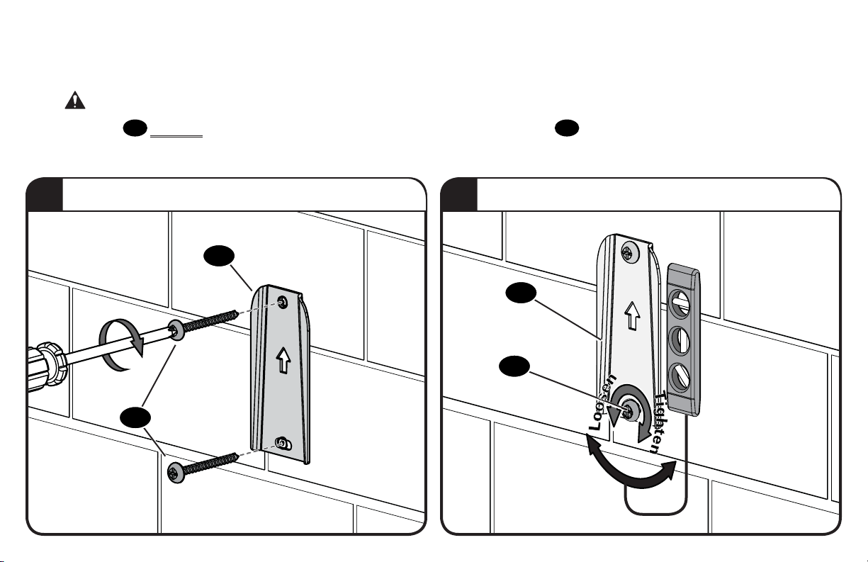
CAUTION:
Both screws
the wall before continuing on to the next step.
Avoid potential personal injury or property damage!
02
MUST BE firmly tightened to prevent unwanted movement of the wall plate
01
Ensure the wall plate is securely fastened to
.
Secure wall plate to wall.
4
02
01
Loosen lower screw for level adjustment - tighten when finished.
5
01
02
11
Page 12
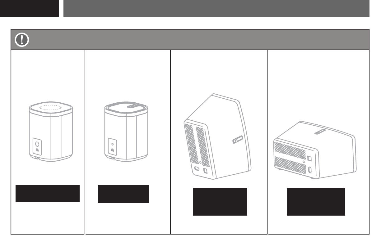
STEP 2
Attach Mount to Speaker
Based on your speaker model, follow the correct STEP 2 below.
Sonos® One
[only]
STEP 2A/2B
PAGE 13 PAGE 18
12
™
Sonos® PLAY:1
[and other speakers]
™
STEP 2C
Sonos® PLAY:3™
Sonos
Horizontal InstallationVertical Installation
STEP 2D
VERTICAL
HORIZONTAL
PAGE 19 PAGE 20
®
PLAY:3™
STEP 2E
Page 13
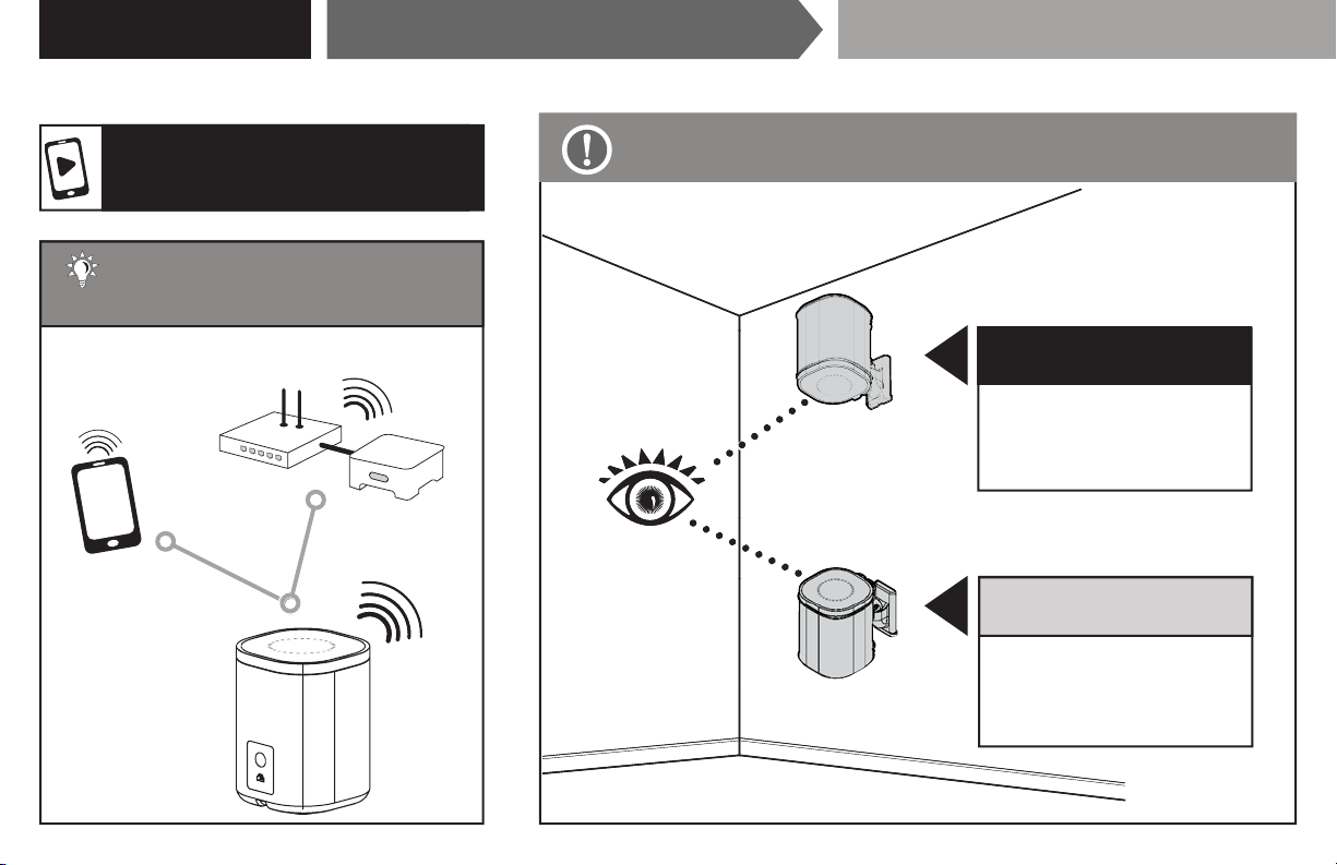
STEP 2A/2B
Attach Mount to Speaker SONOS® One
™
For a helpful install video,
search your model at SANUS.com.
TIP: Set up your Sonos
speaker prior to mounting.
®
Follow the step below based on your installation.
STEP 2A
ABOVE EYE-LEVEL
(speaker upside down)
Follow PAGE 14.
STEP 2B
BELOW EYE-LEVEL
(speaker right-side up)
Follow PAGE 16.
13
Page 14
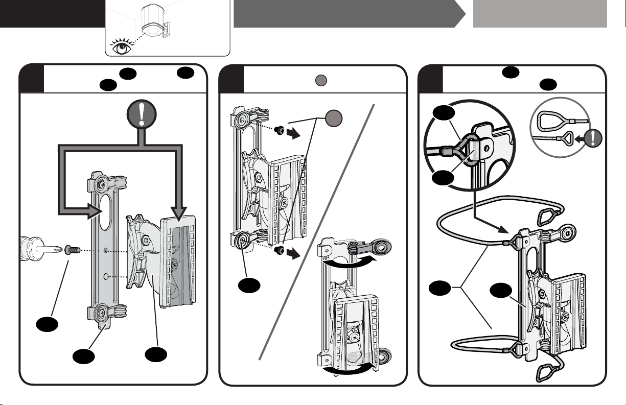
STEP 2A
Above
Eye
Level
Attach Mount to Speaker SONOS® One
™
Attach interface
1
with screw 08.
08
06
to mount 04
06
04
Remove screws S and open clamps.
2 3
S
06
Attach wires 07 (SMALL loop) to
FIXED ends of bracket
07
06
07
06
06
.
14
Page 15
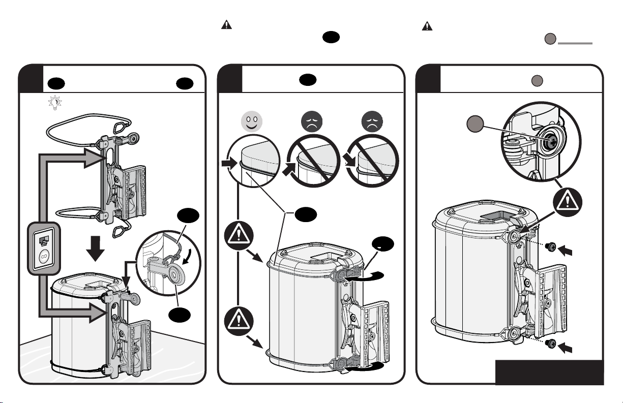
CAUTION: Avoid potential personal injury
or property damage! Wires
extend beyond the speaker's end caps.
07
must NOT
CAUTION: Avoid potential personal injury
or property damage! Both screws
installed to secure the speaker to the mount.
MUST BE
S
Slide over speaker and attach wires
4 6
07
to CLAMP ends of bracket
TIP: Rest speaker UPSIDE DOWN.
06
.
5
Align wires
07
07 and close clamps.
07
06
06
Secure with screws
S
.
S
Go to STEP 3, PAGE 21.
15
Page 16
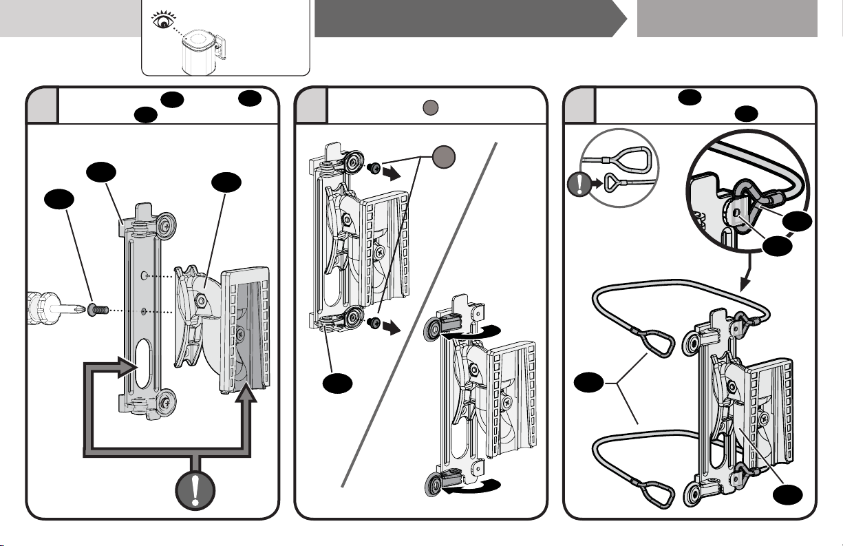
STEP 2B
Below
Eye
Level
Attach Mount to Speaker SONOS® One
™
Attach interface
1 2 3
with screw 08.
06
08
to mount 04
06
Remove screws S and open clamps.
S
04
06
Attach wires 07 (SMALL loop) to
FIXED ends of brackets
07
06
.
07
06
06
16
Page 17
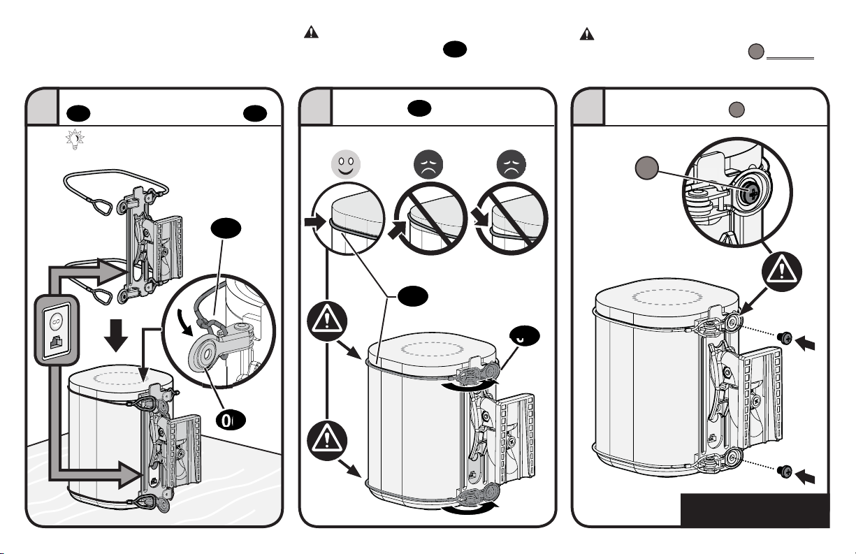
CAUTION: Avoid potential personal injury
or property damage! Wires
extend beyond the speaker's end caps.
07
must NOT
CAUTION: Avoid potential personal injury
or property damage! Both screws
installed to secure the speaker to the mount.
MUST BE
S
Slide over speaker and attach wires
07
to CLAMP ends of bracket
TIP: Rest speaker on flat surface.
06
07
06
Align wires 07 and close clamps.
.
54 6
Secure with screws S.
S
07
06
Go to STEP 3, PAGE 21.
17
Page 18
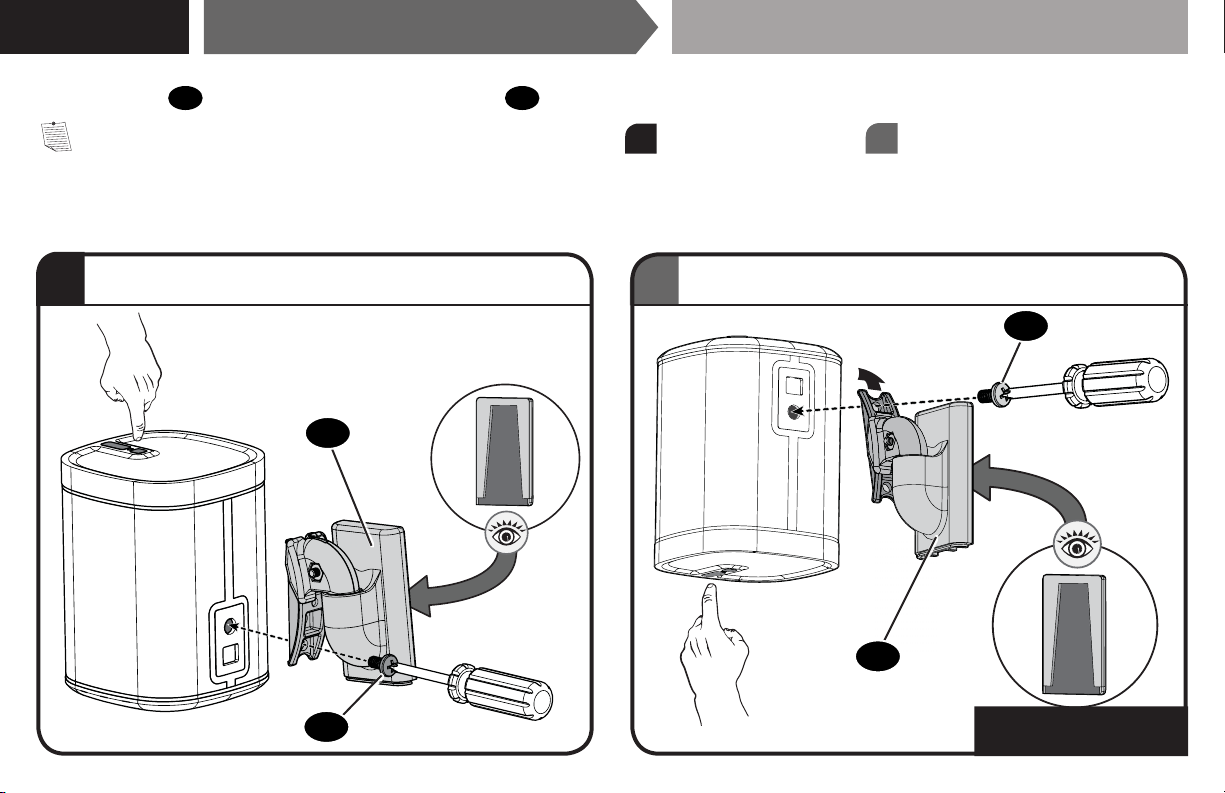
STEP 2C
Attach Mount to Speaker SONOS® PLAY:1
™
[and other speakers]
Attach the mount
NOTE: Speaker may be installed in either the right-side-up position
Right-Side-Up for BELOW Eye Level.
a
04 to your speaker with the speaker screw 09.
04
or up-side-down position
a
Up-Side-Down for ABOVE Eye Level.
b
, depending on height placement.
b
09
04
18
09
Go to STEP 3, PAGE 21.
Page 19
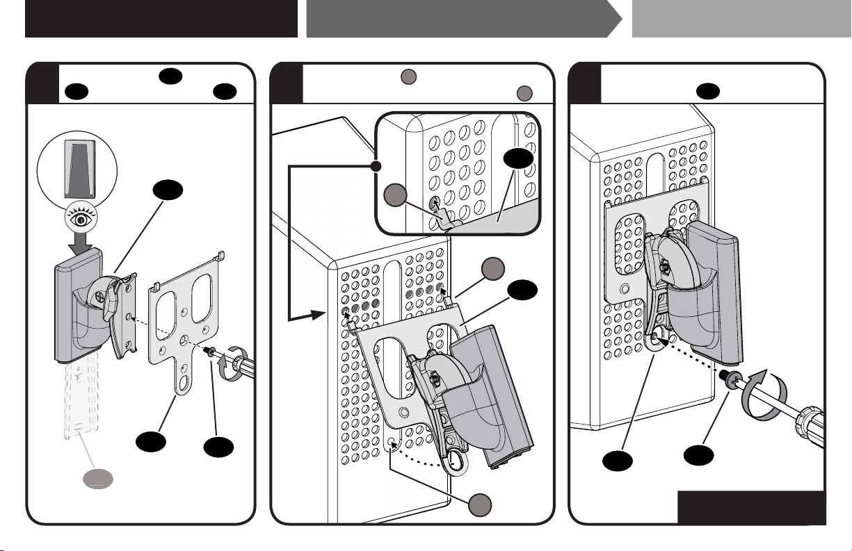
STEP 2D - (VERTICAL)
0101
Attach Mount to Speaker SONOS® PLAY:3
™
Attach interface
1 32
04
with interface screw 08.
05
to mount
04
05
08
Insert both legs L into the 4th holes
from the top, to align the screw hole H.
05
L
L
05
Secure the assembly with the
speaker screw 09.
05
09
H
Go to STEP 3, PAGE 21.
19
Page 20
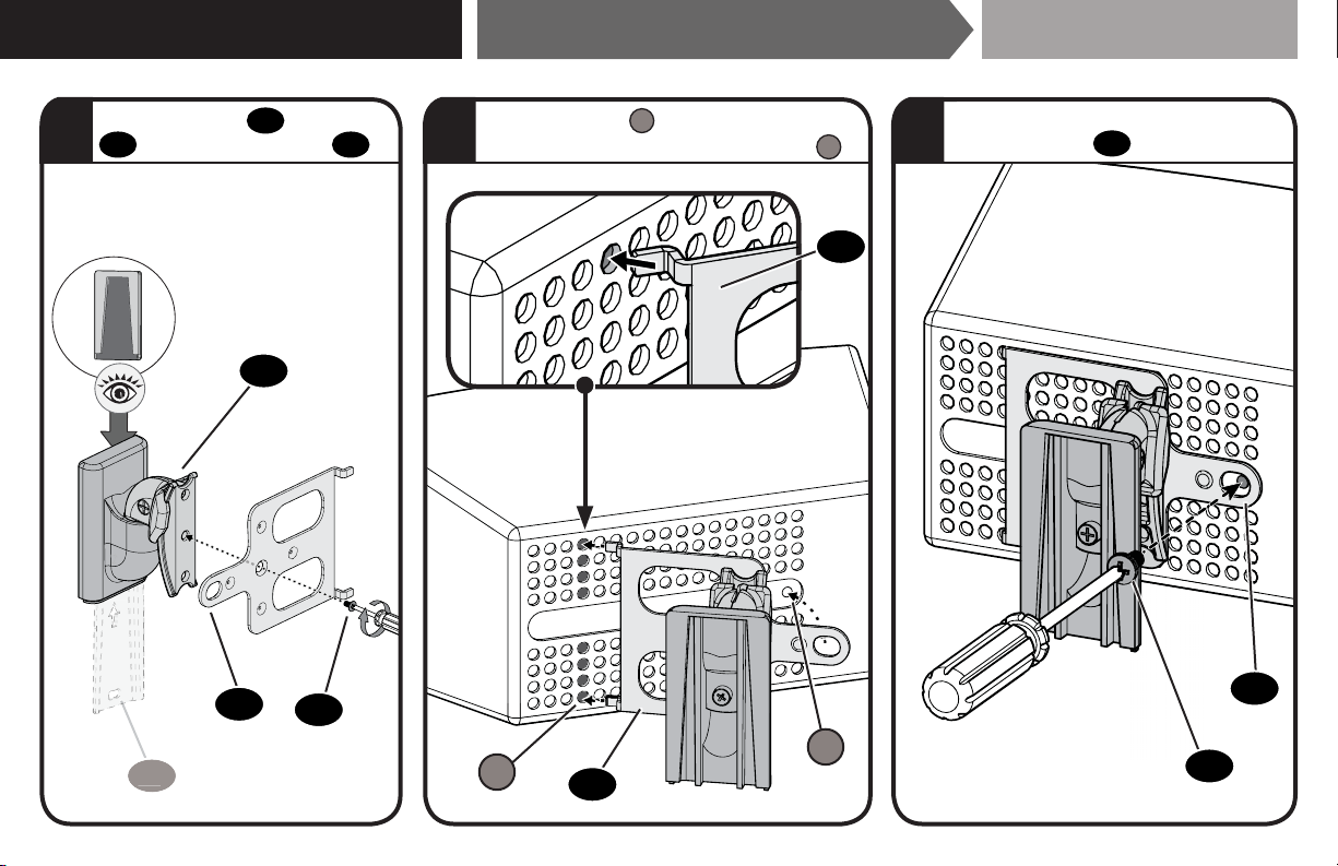
STEP 2E - (HORIZONTAL)
1
Attach Mount to Speaker SONOS® PLAY:3
™
Attach interface
1 32
04
with interface screw 08.
05
to mount
04
05
08
010
Insert both legs
from the end, to align the screw hole H.
into the 4th holes
L
05
H
L
05
Secure the assembly with the
speaker screw 09.
05
09
20
Page 21
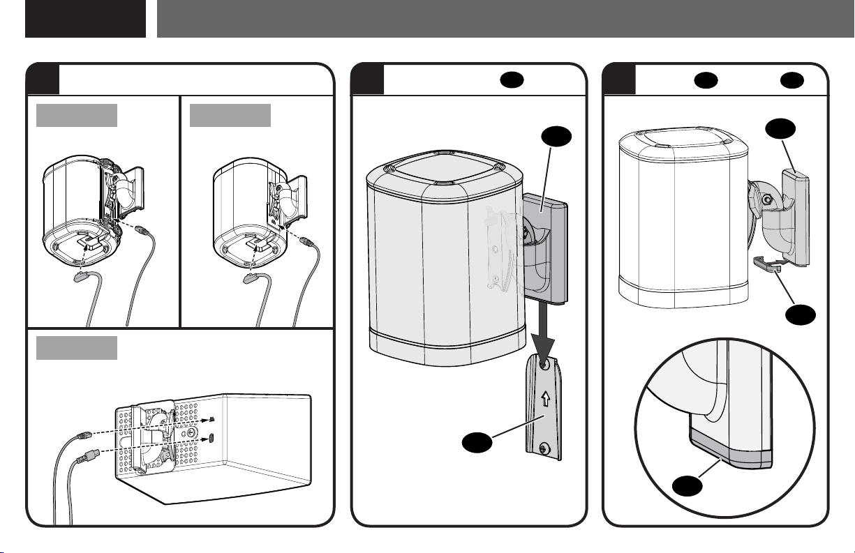
STEP 3
Mount Assembly to Wall Plate
Install cables
One
PLAY:3
™
™
HORIZONTAL SHOWN
PLAY:1
™
Slide onto wall plate 01.
2 31
Play:1™ Shown
01
04
Slide cap 10 onto mount 04.
Play:1™ Shown
04
10
10
21
Page 22
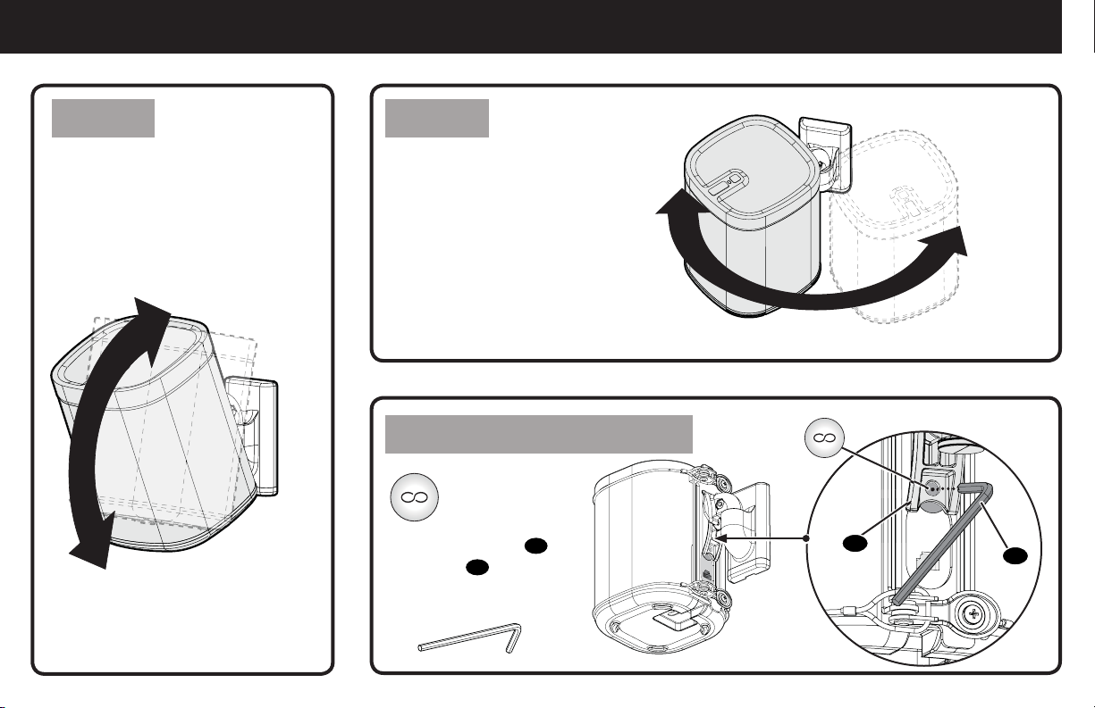
Adjustments
TILT SWIVEL
Your speaker can tilt up or down. Your speaker can
swivel left or right.
One™ Reset Button Access
Access your
Sonos® Infinity
button, through
the hole on mount 04,
Play:1™ Shown
using tool
Play:1™ Shown
04
11
.
11
22
Page 23
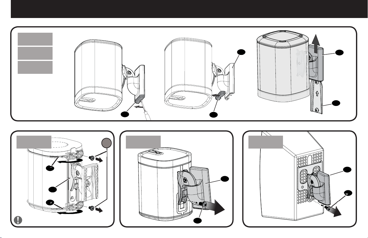
To Remove
™
One
PLAY:1
PLAY:3
™
™
[and other
speakers]
Play:1 Shown
™
One
07
06
07
IMPORTANT: Set on flat surface.
S
10
PLAY:1
™
[and other speakers]
09
04
10
PLAY:3
04
™
04
01
04
09
23
Page 24
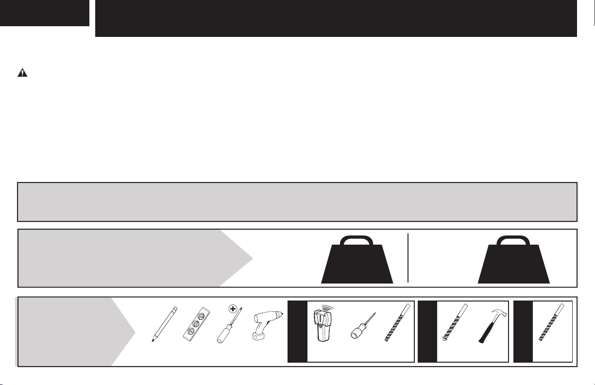
ESPAÑOL
INSTRUCCIONES IMPORTANTES DE SEGURIDAD:
GUARDE ESTAS INSTRUCCIONES Y LEA TODO EL MANUAL ANTES DE UTILIZAR ESTE PRODUCTO.
Antes de comenzar, verifi quemos que este producto sea el ideal para sus necesidades.
PRECAUCIÓN: Evite posibles lesiones personales y daños materiales.
● Consulte el manual del usuario de su altavoz para ver si existe algún requisito especial para instalar su altavoz en la pared.
● Lea estas instrucciones en su totalidad para sentirse seguro y cómodo con este fácil proceso de instalación.
● No utilice este producto para ningún otro propósito que no sea el explícitamente especifi cado por el fabricante.
● El fabricante no se responsabiliza por ningún daño o lesión resultante del montaje incorrecto o del uso indebido.
● La pared debe ser capaz de soportar hasta cinco veces el peso combinado del altavoz y el soporte.
● Si no entiende las instrucciones o si tiene dudas acerca de la seguridad de la instalación, del ensamblado o del uso del producto, póngase
en contacto con el servicio de atención al cliente al 1-800-359-5520.
Los soportes para altavoces fueron concebidos para sostener altavoces Sonos® One™, PLAY:1™ y
PLAY:3™, así como la mayoría de altavoces pequeños que admiten soporte.
Peso máximo
NO EXCEDAS
herramientas
necesarias
24
Lápiz Nivel Destornillador
Play:1™
Taladro
eléctrico
One™
Instalación sobre
montante de madera
Localizador
de montantes
1.8 kg
(4 lbs.)
Punzón
3 mm
(1/8 pulg.)
Broca para
madera
Play:3™
[Y otros
altavoces]
6,5 mm
(1/4 pulg.)
Instalación
Broca para
sobre hormigón
mampostería
4.5 kg
(10 lbs.)
Martillo
6,5 mm
(1/4 pulg.)
Broca para
Instalación en
tabique de pared
tabiques
Page 25
Dimensiones
página 3
ESPAÑOL
Piezas y elementos de sujeción suministrados página 4
ADVERTENCIA: Este producto contiene piezas pequeñas que, en caso de ser tragadas, podrían causar asfixia.
Antes de comenzar a montar la unidad, verifique que dispone de todas las piezas y que se encuentran en buen estado. Si no dispone de todas las piezas o alguna
está dañada, no devuelva el elemento defectuoso al distribuidor. Póngase en contacto con el servicio de atención al cliente. Nunca utilice piezas en mal estado.
NOTA: No se utilizarán todos los elementos de sujeción incluidos. Las cantidades que se muestran corresponden a un soporte para altavoces.
PASO 1A
Fijar la placa mural a la pared
Opción de tabique
PRECAUCIÓN: ¡Evite posibles lesiones personales o daños materiales!
● Los paneles de yeso que cubren la pared no deben medir menos de 6,5 mm (1/4 pulg.).
PRECAUCIÓN: Evite posibles lesiones personales o daños materiales. Ambos tornillos
01
el movimiento de la placa mural
PASO 1B
Fijar la placa mural a la pared
Asegúrese de que la placa mural esté bien fijada a la pared antes de continuar con el paso siguiente.
.
02
DEBEN ESTAR apretados con firmeza para evitar
Opción montante de madera
PRECAUCIÓN: ¡Evite posibles lesiones personales o daños materiales!
● Los paneles de yeso que cubren la pared no deben superar los 16 mm (5/8 pulg.)
● Tamaño mínimo de los montantes de madera: nominal 51 x 102 mm (2 x 4 pulg.) actual 38 x 89 mm (1½ x 3½ pulg.)
● Debe comprobar el centro del montante
PRECAUCIÓN: ¡Evite posibles lesiones personales o daños materiales! Ambos tornillos
01
movimiento de la placa mural
PASO 1C
Asegúrese de que la placa mural esté bien fijada a la pared antes de continuar con el paso siguiente.
.
Fijar la placa mural a la pared
02
DEBEN ESTAR apretados con firmeza para evitar el
hormigón macizo o bloques de hormigón
PRECAUCIÓN: ¡Evite posibles lesiones personales o daños materiales!
● Monte la placa mural
● Grosor mínimo del hormigón macizo: 203 mm (8 pulg.)
● Tamaño mínimo del bloque de hormigón: 203 x 203 x 406 mm (8 x 8 x 16 pulg.)
PRECAUCIÓN: ¡Evite posibles lesiones personales o daños materiales! Ambos tornillos
movimiento de la placa mural
01
directamente sobre la superficie de hormigón
01
Asegúrese de que la placa mural esté bien fijada a la pared antes de continuar con el paso siguiente.
.
DEBEN ESTAR apretados con firmeza para evitar el
02
página 6
página 8
página 10
25
Page 26
ESPAÑOL
PASO 2
Fijar el soporte de pared al altavoz
Siga los siguientes pasos según el estilo de su altavoz.
Para Sonos® One™ - consulte PASO 2A/2B en la PÁGINA 13
Para Sonos® Play:1™ - consulte PASO 2C en la PÁGINA 18
Para Sonos® Play:3™ (vertical) - consulte PASO 2D en la PÁGINA 19
Para Sonos® Play:3™ (horizontal) - consulte PASO 2E en la PÁGINA 20
PASO 2A/2B
Siga los siguientes pasos basados en su instalación.
Para extremo superior hacia arriba - consulte la PÁGINA 14.
Para extremo inferior hacia arriba - consulte la PÁGINA 16.
PASO 2A -
NOTA: Coloque el altavoz sobre una superficie plana.
PRECAUCIÓN: Evite posibles lesiones físicas y daños materiales. Los cables
PRECAUCIÓN: Evite posibles lesiones físicas y daños materiales. Ambos tornillos
PASO 2B -
NOTA: Coloque el altavoz sobre una superficie plana.
PRECAUCIÓN: Evite posibles lesiones físicas y daños materiales. Los cables
PRECAUCIÓN: Evite posibles lesiones físicas y daños materiales. Ambos tornillos
26
Extremo superior
hacia arriba
Extremo inferior
hacia arriba
Fijar el soporte de pared al altavoz
Fijar el soporte de pared al altavoz
07
Fijar el soporte de pared al altavoz
07
Sonos® One
™
Sonos® One
NO deben extenderse más allá de la cubierta del altavoz.
S
DEBEN instalarse para fijar el altavoz al soporte.
Sonos® One
NO deben extenderse más allá de la cubierta del altavoz.
S
DEBEN instalarse para fijar el altavoz al soporte.
página 12
página 13
™
página 14
™
página 16
Page 27
ESPAÑOL
PASO 2C
Fije el soporte
NOTA: Puede instalar el altavoz con la parte derecha hacia arriba (a) o boca abajo (b), en función de sus necesidades.
04 al altavoz Play:1 con el tornillo del altavoz 09.
PASO 2D - (vertical)
1. Fije el soporte de conexión del Play:3 05 al soporte 04 con el tornillo 08.
2. Monte el conjunto en el altavoz Play:3 insertando las patas del soporte de conexión del Play:3
el soporte
3. Fije el conjunto al altavoz Play:3 con el
sobre el altavoz.
05
tornillo del altavoz 09.
PASO 2E -(horizontal)
1. Fije el soporte de conexión del Play:3
2. Monte el conjunto en el altavoz Play:3 insertando las patas del soporte de conexión del Play:3
el soporte
3. Fije el conjunto al altavoz Play:3 con el
PASO 3
1. Pasar el cable de alimentación de los altavoces
2. Deslice el conjunto del altavoz/placa mural sobre la placa mural
3. Ponga la tapa
sobre el altavoz.
05
Montar el conjunto a la placa mural
sobre el soporte 04 para completar el montaje.
10
al soporte 04 con el tornillo 08.
05
tornillo del altavoz
Fijar el soporte de pared al altavoz
Fijar el soporte de pared al altavoz
en los últimos cuatro orificios desde el final y apoyando
05
Fijar el soporte de pared al altavoz
en los últimos cuatro orificios desde el final y apoyando
05
.
09
.
01
Sonos® Play:1
Sonos® Play:3
Sonos® Play:3
página 21
Ajustes página 22
Puede inclinar los altavoces sobre el soporte.
Puede girar los altavoces sobre el soporte como desee.
™
página 18
™
página 19
™
página 20
Para retirar página 23
PRECAUCIÓN: ¡ Coloque el altavoz sobre una superficie plana.
27
Page 28
Thank you for choosing SANUS! Please take a moment to let us know how we did:
Call us: 1-800-359-5520
Email us: [email protected]
Leave a review: sanus.com
Milestone AV Technologies and its a liated corporations and subsidiaries (collectively, “Milestone”), intend to make this manual accurate and complete. However,
Milestone makes no claim that the information contained herein covers all details, conditions, or variations. Nor does it provide for every possible contingency in
connection with the installation or use of this product. The information contained in this document is subject to change without notice or obligation of any kind.
Milestone makes no representation of warranty, expressed or implied, regarding the information contained herein. Milestone assumes no responsibility for accuracy,
completeness or su ciency of the information contained in this document.
©2017 Milestone AV Technologies. All rights reserved. SANUS is a division of Milestone.
All other brand names or marks are used for identifi cation purposes and are trademarks of their respective owners.
SANUS • 6436 City West Parkway • Eden Prairie, MN 55344 USA 6901-602165 00
 Loading...