

Page 1
WSTV1 INSTRUCTION MANUAL
We’ll Make It Stress-Free
If you have any questions along the way, just give us a call.
1-800-359-5520. We’re ready to help!
Page 2
IMPORTANT SAFETY INSTRUCTIONS – SAVE THESE INSTRUCTIONS – PLEASE READ ENTIRE MANUAL PRIOR TO USE
Before getting started, let’s make sure this mount is perfect for you!
Does your TV weigh more than 60 lbs. (27.2 kg) including accessories?
1
60 lbs.
Yes
(27.2 kg)
Do you have
2
3
the tools needed?
Ready to begin?
Please read through these instructions completely to be sure you’re comfortable with this easy install process. Also check your TV owner’s manual to
see if there are any special requirements for mounting your TV.
If you do not understand these instructions or have doubts about the safety of the installation, assembly or use of this product, contact Customer
Service at 1-800-359-5520.
CAUTION: Avoid potential personal injuries and property damage! Manufacturer is not responsible for damage or injury caused by incorrect
assembly or use.
WARNING: Exceeding the weight capacity can result in serious personal injury or damage to equipment! It is the installer’s responsibility to
make sure the combined weight of the WSTV1 and the display does not exceed 60 lbs (27.2 kg). Use with heavier televisions may result in instability
causing tip over resulting in death or serious injury!
WARNING: Use this mounting system only for its intended use as described in these instructions. Do not use attachments not recommended by
the manufacturer.
WARNING: Death or serious injury may occur when children climb on audio and/or video equipment furniture. A remote control or toys placed
on the furnishing may encourage a child to climb on the furnishing and as a result the furnishing may tip over onto the child.
WARNING: Relocating audio and/or video equipment to furniture not specifi cally designed to support audio and/or video equipment may result
in death or serious injury due to the furnishing collapsing or overturning onto a child.
NOTE: The WSTV1 can support screen sizes up to a maximum of 60" diagonal.
NOTE: The WSTV1 has no user serviceable parts.
No — Perfect!
—
This mount is NOT compatible. Visit sanus.com or call 1-800-359-5520 (UK: 0800-056-2853) to fi nd a compatible mount.
Level Screwdriver
2
Page 3
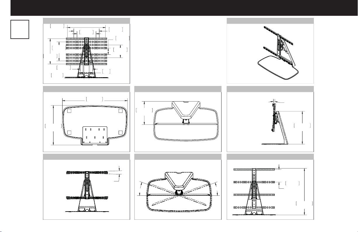
Dimensions
in.
[mm]
TV INTERFACE
600mm
400mm
15.75 in.
23.62 in.
300mm
11.81 in.
75mm
2.95 in.
200mm
7.87 in.
300mm
11.81 in.
100
3.94 in.
BASE PLATE
685.8mm
417.8mm
16.45 in.
27.00 in.
FULLY ASSEMBLED MOUNT
3deg ROLL
400mm
15.75 in.
100mm
3.94 in.
200mm
7.87 in.
TOP VIEW - EXTENDED
243.9mm
9.60 in.
TOP VIEW - RETRACTED
20deg
3-D
SIDE VIEW - EXTENDED
FRONT VIEW - HEIGHT ADJUST
20deg
5deg
UPTILT
200mm
7.87 in.
HEIGHT
ADJUST
519.7mm
20.46 in.
735.9mm
28.97 in.
3
Page 4
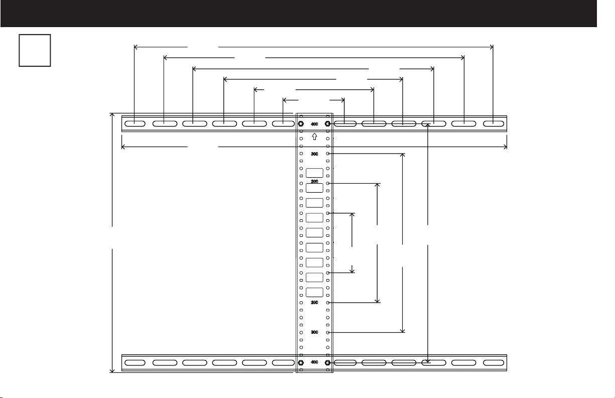
Dimensions - TV Interface
in.
[mm]
17.13 in.
(435 mm)
23.62 in.
(600 mm)
25.36 in.
(644.16 mm)
19.69 in.
(500 mm)
7.87 in.
(200 mm)
4.00 in.
(100 mm)
11.81 in.
(300 mm)
4.00 in.
(100 mm)
15.75 in.
(400 mm)
7.87 in.
(200 mm)
15.75 in.
(400 mm)
11.75 in.
(300 mm)
4
Page 5
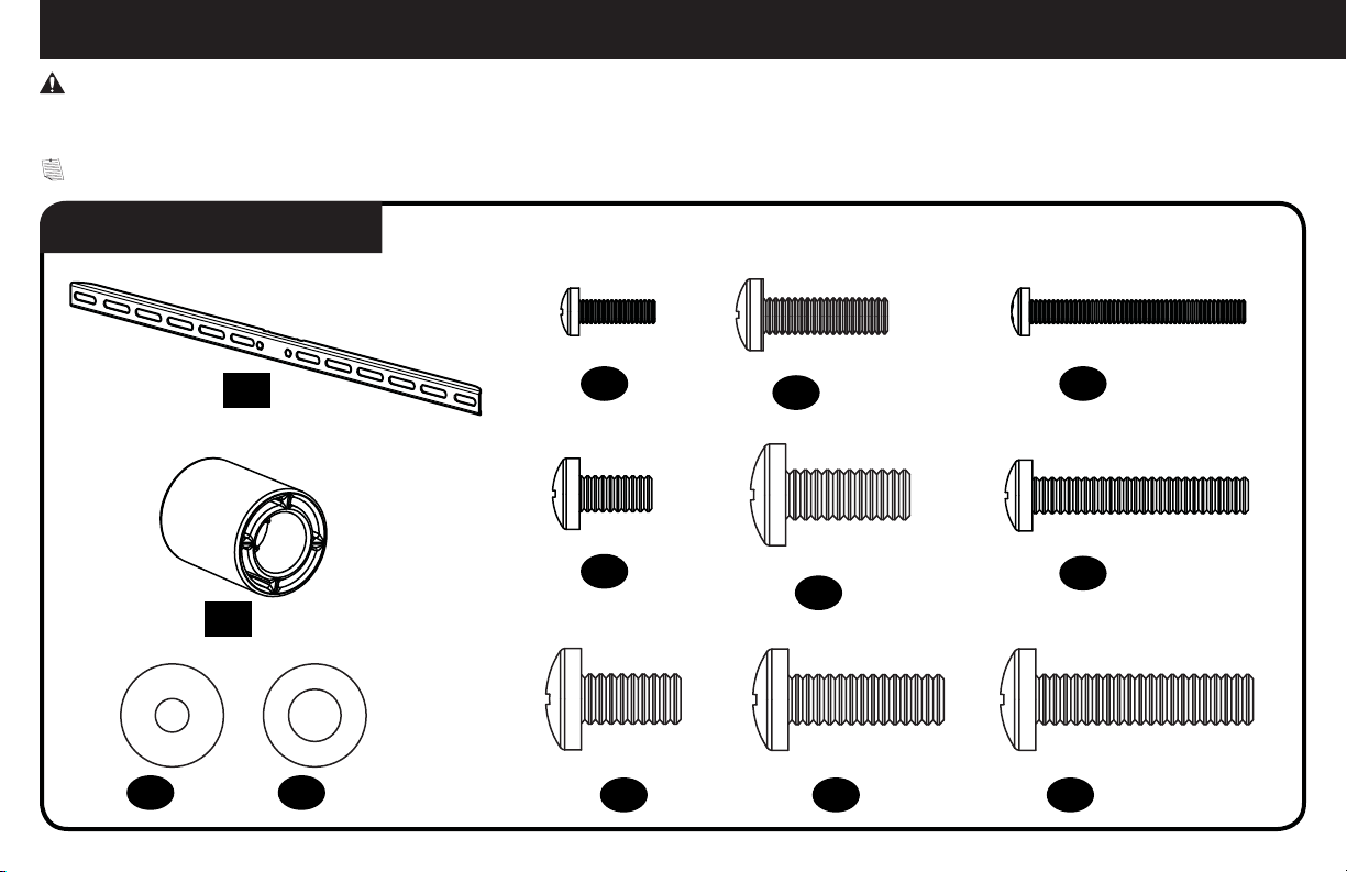
M8 x 35mm
M
6
/
M
8
M
4
M4 x 12mm
M6 x 12mm
M6 x 35mm
M4 x 35mm
M6 x 20mm
M8 x 20mm
M8 x 16mm
M8 x 25mm
Supplied Parts and Hardware
WARNING: This product contains small items that could be a choking hazard if swallowed.
Before starting assembly, verify all parts are included and undamaged. If any parts are missing or damaged, do not return the damaged item to
your dealer; contact Customer Service. Never use damaged parts!
NOTE: Not all hardware included will be used.
STEP 1 Parts and Hardware
TV Bracket
01 x2
Spacers
02 x4
Washers
03 x4 04 x4
TV Screws
05 x4
08 x4
06 x4
07 x4 10 x4 13 x4
09 x4
11 x4
12 x4
5
Page 6
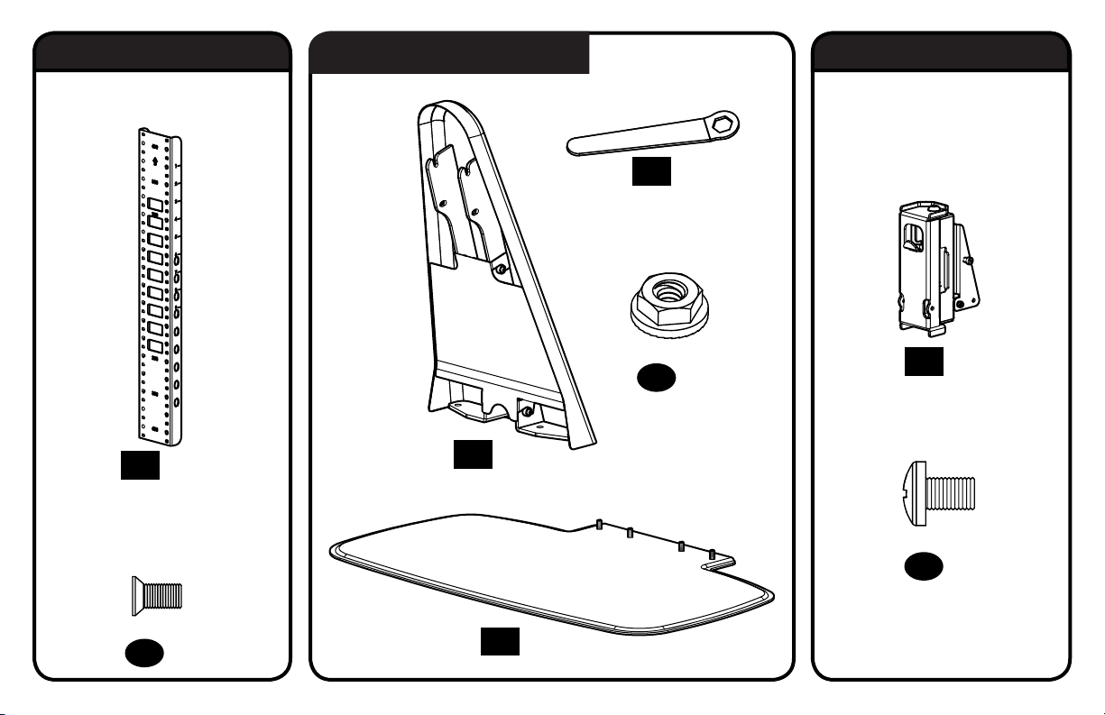
10-32 x 3/8 in.
1/4-20 x 3/8 in.
STEP 2 Parts and Hardware STEP 4 Parts and Hardware
STEP 3 Parts and Hardware
Vertical Height Adjustment
Bracket
14 x1
Interface Screws
for Vertical Height
Adjustment Bracket
Neck
16 x1
Attachment Nuts
Base
Wrench
18 x1
1/4-20
19 x4
Swivel Head
20 x1
Lock Screws
21 x4
15 x4
6
17 x1
Page 7
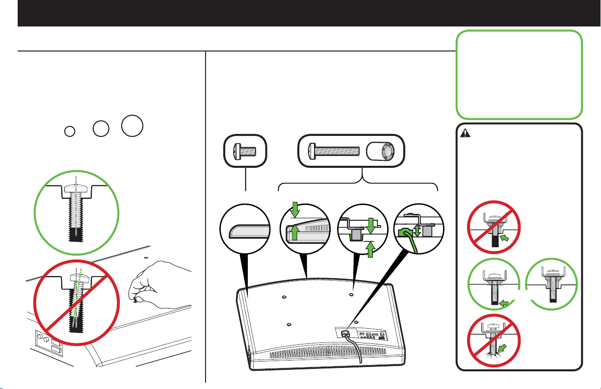
STEP 1 Attach TV Brackets to TV
1.1 Select TV Screw Diameter
Hand thread screws into the threaded inserts
on the back of your TV to determine which
screw diameter (M4, M6, or M8) to use.
M6M4 M8
1.2 Select TV Screw Length
If your TV has a flat back AND you want your TV closer to the
swivel head of the mount, use the shorter screws.
Spacers and longer screws are supplied to accommodate:
● Round/irregular back TVs
● TVs with inset mounting holes
● Extra space needed for cables
FLAT BACK ROUND BACK CABLESINSET HOLES
Standard configurations
are shown. For special
applications, or if you
are uncertain about your
hardware selection, contact
Customer Service at
1-800-359-5520.
CAUTION:
Verify adequate thread
engagement with your screw/
washer/spacer combination AND
TV bracket.
- Too short will not hold the TV.
- Too long will damage the TV.
Too Short
Correct
Too Long
7
Page 8
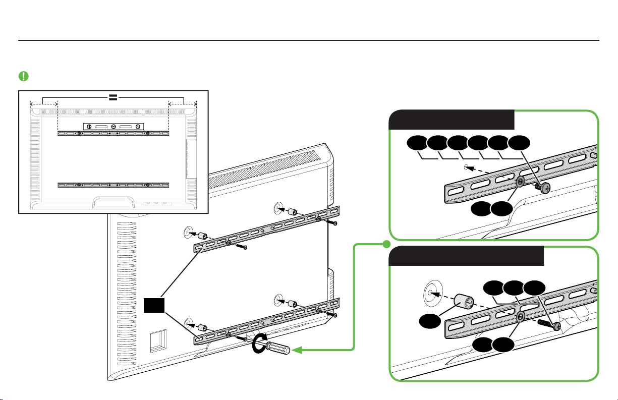
1.3 Attach Horizontal Brackets
Position your TV brackets over your TV hole pattern - making sure the brackets are centered over the TV hole pattern and level. Secure brackets
using your screw/washer (Flat Back) or spacer/screw/washer (Round Back / Extra Space) selection (see 1.2 page 7).
IMPORTANT: Ensure TV brackets are securely fastened before moving on to the next step.
Flat Back
05 06 070208 091210
03
04
Round Back / Extra Space
11
13
01
03
04
8
Page 9
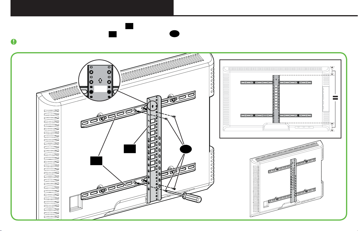
STEP 2 Attach Vertical Bracket
Make sure the vertical height adjustment bracket 14 is centered on the TV.
UP
14
with interface screws 15.
Secure vertical height adjustment bracket
IMPORTANT: Ensure all brackets are securely fastened before moving on to the next step.
01
14
15
9
Page 10
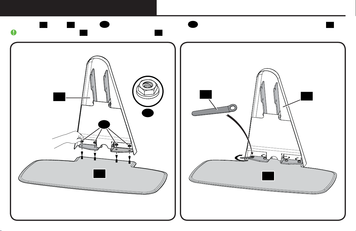
STEP 3 Attach Neck to Base
1/4-20
Attach neck 16 to base 17 with nuts 19. Start by hand tightening the nuts 19 then complete the tightening by using supplied wrench 18.
IMPORTANT: Ensure neck 16 is securely fastened to base 17 before moving on to the next step.
10
16
17
19
19
18
16
17
Page 11
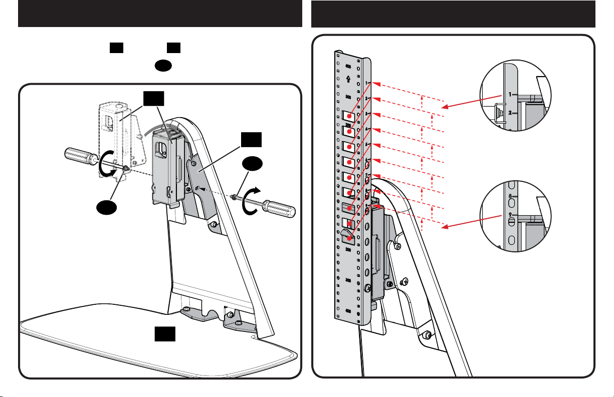
STEP 4 Swivel Head to Neck
2”
3”
1”
4”
5”
6”
7”
8”
9”
1. Hang swivel head 20 onto neck 16.
STEP 5 Attach TV to Swivel Head
2. Secure with two lock screws
21
20
21
17
.
16
Lowest Position
21
Highest Position
11
Page 12
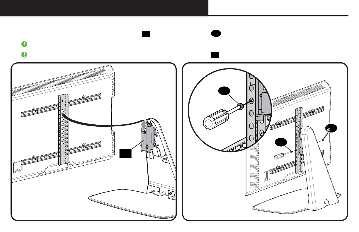
STEP 5 Attach TV to Swivel Head (continued)
1. Determine the height from the base that you would like to hang your TV (see examples Page 11).
2. Secure the TV/bracket assembly to the swivel head
IMPORTANT: Keep the base clear while installing TV.
IMPORTANT: Ensure TV/bracket assembly is securely fastened to swivel head 20 before moving on to the next step.
20
with the two lock screws 21.
21
20
21
21
12
Page 13
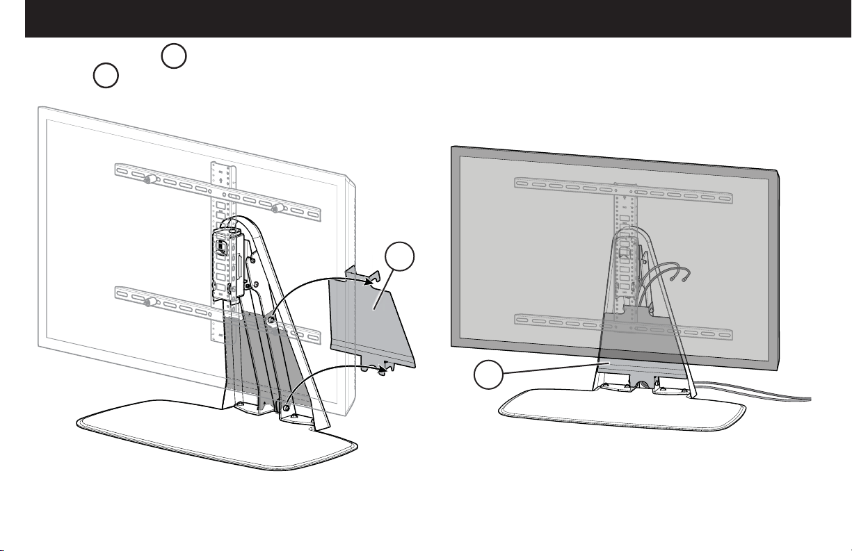
Cable Management
Remove the cable cover CC. Route cables down the cable channel of the neck and through the opening in the base of the neck. Replace the
cable cover CC.
CC
CC
13
Page 14
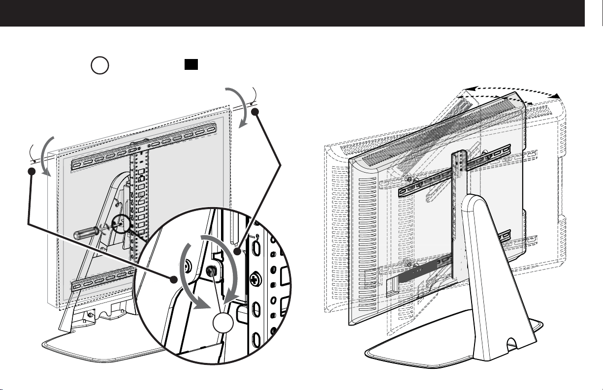
Adjustments
adjustment screw AS in the swivel head 20.
TV can be swiveled ±20° (40° total) for best viewing angle.Post install leveling can be adjusted ± 1.5 degrees using the
±1.5°
Counterclockwise
Clockwise
AS
±1.5°
20°
40°
20°
14
Page 15
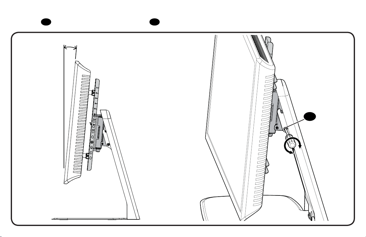
TV can be tilted back 5° for a better viewing angle or to compensate for deflection caused by a heavy TV. To adjust tilt, loosen both
lock screws 21, adjust tilt, then tighten both lock screws 21.
5°
21
15
Page 16

Thank you for choosing Sanus! Please take a moment to let us know how we did:
DRAFT COPY
Call us: 1-800-359-5520
Milestone AV Technologies and its a liated corporations and subsidiaries (collectively, “Milestone”), intend to make this manual accurate and complete. However,
Milestone makes no claim that the information contained herein covers all details, conditions, or variations. Nor does it provide for every possible contingency in
connection with the installation or use of this product. The information contained in this document is subject to change without notice or obligation of any kind.
Milestone makes no representation of warranty, expressed or implied, regarding the information contained herein. Milestone assumes no responsibility for accuracy,
completeness or su ciency of the information contained in this document.
©2016 Milestone AV Technologies. All rights reserved. Sanus is a division of Milestone.
All other brand names or marks are used for identifi cation purposes and are trademarks of their respective owners.
SANUS • 6436 City West Parkway • Eden Prairie, MN 55344 USA 6901-002591 00
Email us: [email protected] Leave a review: sanus.com
UK: 0800 056 2853
Find us on Facebook: SANUS Follow us on Twitter @sanussystems
 Loading...