

Sanus VMUC1S User Manual
Assembly Instructions for Model: VMUC1
Thank you for choosing a Sanus Systems Vision Mount under cabinet mount. The
VMUC1 is designed to hold up to a 17 inch at panel LCD weighing up to 18
lbs.
Safety Warning: If you do not understand these directions, or have any doubts
about the safety of the installation, please call a qualied contractor or contact Sanus at 800.359.5520 or www.sanus.com. Check carefully to make sure that there
are no missing or defective parts. Our customer service representatives can quickly
assist you with installation questions and missing or damaged parts. Replacement
parts for products purchased through authorized dealers will be shipped directly to
you. Never use defective parts. Improper installation may cause damage or serious
injury. Do not use this product for any purpose that is not explicitly specied by
Sanus Systems. Sanus Systems can not be liable for damage or injury caused by incorrect mounting, incorrect assembly, or incorrect use. Please call Sanus Systems
before returning products to the point of purchase.
Required Tools: Phillips screw driver, drill, 1/4 inch drill bit
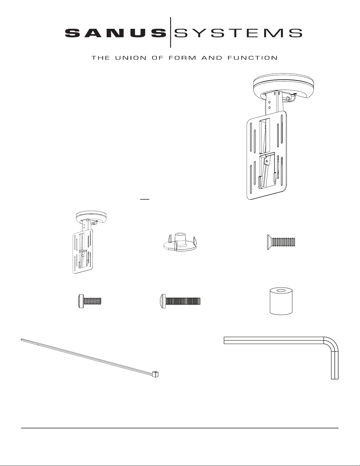
Supplied Parts and Hardware: Some parts not shown as actual size*
(3) T - Nuts - b (3) 10-24 x 5/8 Bolt - c
(1) Mount Assembly - a
(4) M4 x 10 mm Bolt - d (4) M4 x 20 mm Bolt - e
(4) .5 inch Spacer - f
(4) Cable Tie - g (1) Allen Key - h
Sanus Systems 2221 Hwy 36 West, Saint Paul, MN 55113 1.3.05
Customer Service: 800.359.5520. See complementary Sanus products at www.sanus.com

Step 1: Remove Cover
1.89 1.89
3.28
Using a Phillips screw driver loosen the two at head bolts from the cover and slide it down and away from the mounting plate. See
Diagram 1 for assistance. You will re-install the cover once cable management is complete.
Diagram 1
a
mounting plate
cover at head bolts
Step 2: Prepare Mounting Surface
Use the base of the Mount Assembly
(a) as a template to mark three holes
in the cabinet in the desired location.
Drill three 1/4 inch holes at the marked
locations.
See the dimensional drawing on the
right for assistance.
See page 9 for a 1:1 scaled version of
the dimensional drawing.
Dimensional Drawing
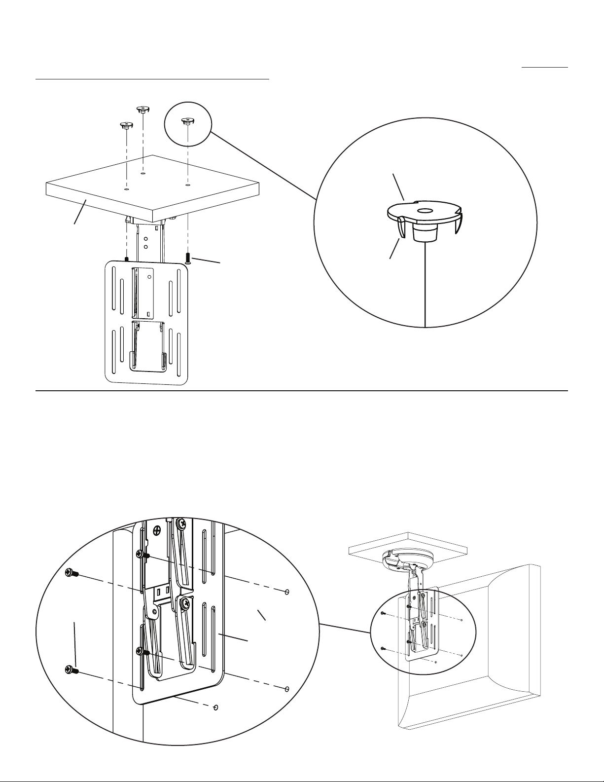
Step 3: Secure Mount Assembly to cabinet
Using the 10-24 x 5/8 Bolts (c) and the T - Nuts (b) secure the Mount Assembly to the cabinet. See Diagram 3 for assistance. Note: Make
sure the spikes on the T - Nuts is facing toward the cabinet.
Diagram 3
Detailed View
b
cabinet
c spike
Step 4: Attach at panel display to mounting plate
Make sure no power is supplied to the display before mounting the display!
Warning: Watch for pinch points. Do not put your ngers or cables between movable parts.
Once the Mount Assembly (a) is secured to the cabinet, align the appropriate slots in the mounting plate with the four mounting holes of
your LCD display. Use either four M4 x 10 mm Bolts (d) or four M4 x 20 mm Bolts (e) with four .5 inch Spacers (f). Diagram 4a below
shows the M4 x 10 mm Bolts being used. Diagram 4b on the next page shows the M4 x 20 mm Bolts with the .5 inch Spacers.
Detailed View
Diagram 4a
LCD panel
d
mounting plate
 Loading...