

ESPAÑOL
FRANÇAIS ITALIANO PYCCKO
ENGLISH
International Assembly Instructions for model VMUC1
Sanus Systems 2221 Hwy 36 West, Saint Paul, MN 55113 USA (6901-300074 <02>)
Customer Service: (800) 359-5520 • (651) 484-7988 • fax (651) 636-0367
www.sanus.com
中文

ENGLISH
Assembly Instructions for Model: VMUC1
Thank you for choosing a Sanus Systems Vision Mount under cabinet mount. The
VMUC1 is designed to hold up to a 17 inch flat panel LCD weighing up to 15
lbs.
Safety Warning: If you do not understand these directions, or have any doubts
about the safety of the installation, please call a qualified contractor or contact
Sanus at 800.359.5520 or www.sanus.com. Check carefully to make sure that there
are no missing or defective parts. Our customer service representatives can quickly
assist you with installation questions and missing or damaged parts. Replacement
parts for products purchased through authorized dealers will be shipped directly to
you. Never use defective parts. Improper installation may cause damage or serious
injury. Do not use this product for any purpose that is not explicitly specified by
Sanus Systems. Sanus Systems can not be liable for damage or injury caused by incorrect mounting, incorrect assembly, or incorrect use. Please call Sanus Systems
before returning products to the point of purchase.
Required Tools: Phillips screw driver, drill, 1/4 inch drill bit
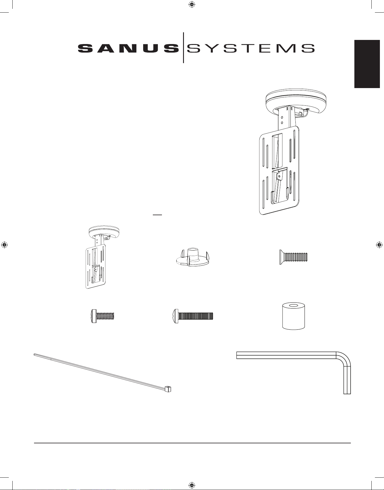
Supplied Parts and Hardware: Some parts not shown as actual size*
(3) T - Nuts - b (3) 10-24 x 5/8 Bolt - c
(1) Mount Assembly - a
(4) M4 x 10 mm Bolt - d (4) M4 x 20 mm Bolt - e
(4) .5 inch Spacer - f
(4) Cable Tie - g (1) Allen Key - h
Sanus Systems 2221 Hwy 36 West, Saint Paul, MN 55113 USA (6901-300074 <02>)
Customer Service: 800.359.5520. See complementary Sanus products at www.sanus.com
ENGLISH
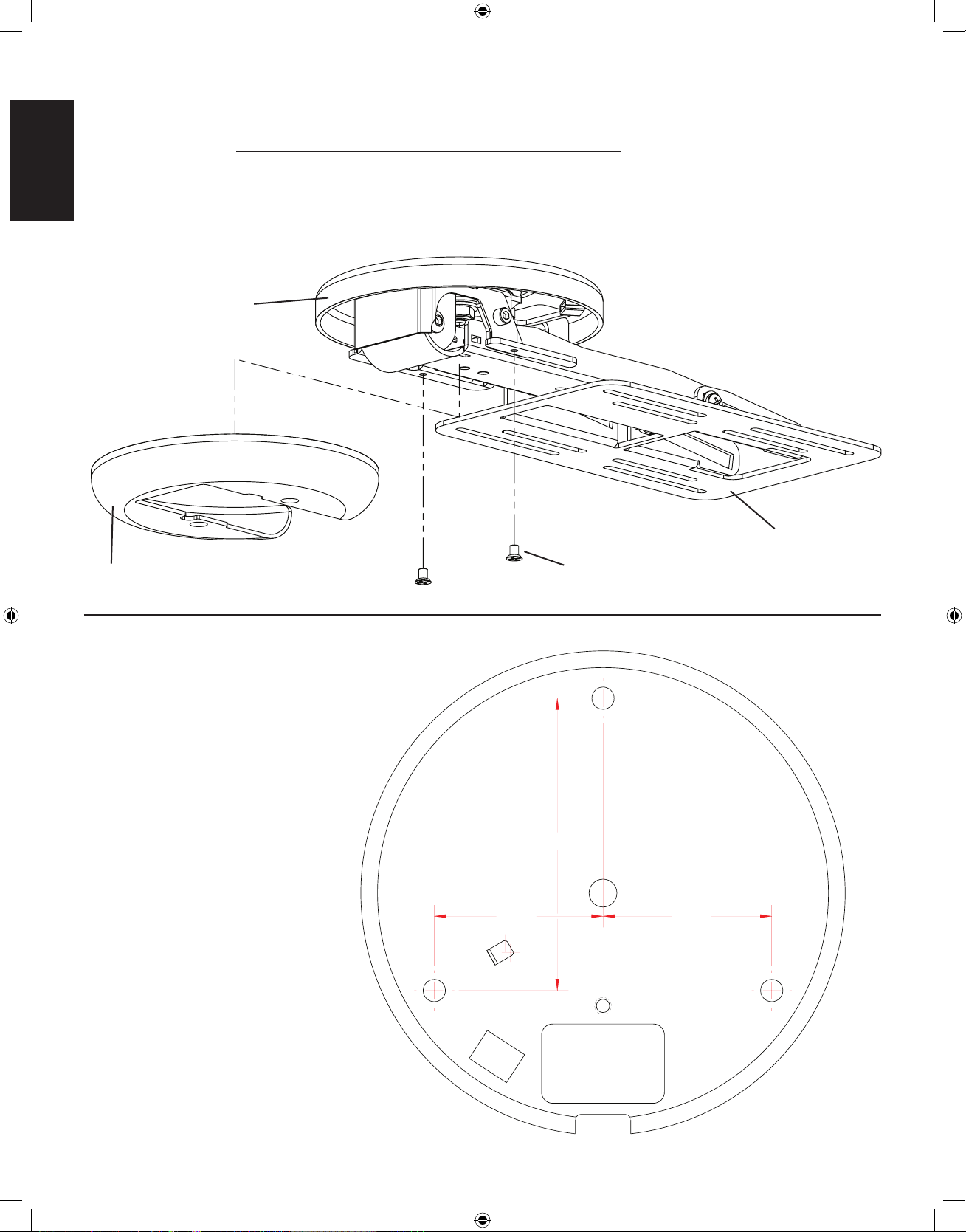
1.89 1.89
3.28
Step 1: Remove Cover
Using a Phillips screw driver loosen the two flat head bolts from the cover and slide it down and away from the mounting plate. See
Diagram 1 for assistance. You will re-install the cover once cable management is complete.
Diagram 1
a
mounting plate
cover at head bolts
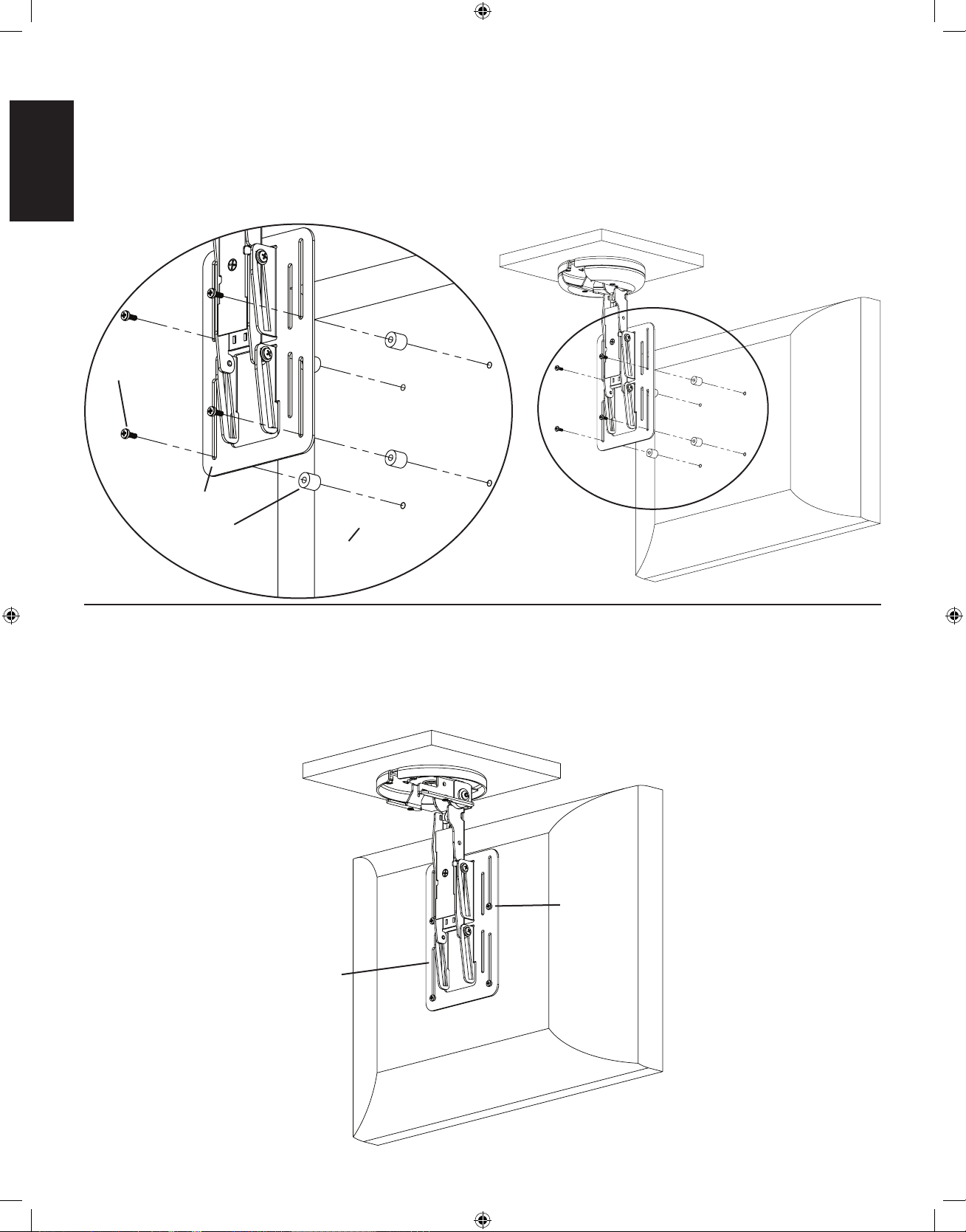
Step 2: Prepare Mounting Surface
Use the base of the Mount Assembly
(a) as a template to mark three holes
in the cabinet in the desired location.
Drill three 1/4 inch holes at the marked
locations.
See the dimensional drawing on the
right for assistance.
Dimensional Drawing
ENGLISH
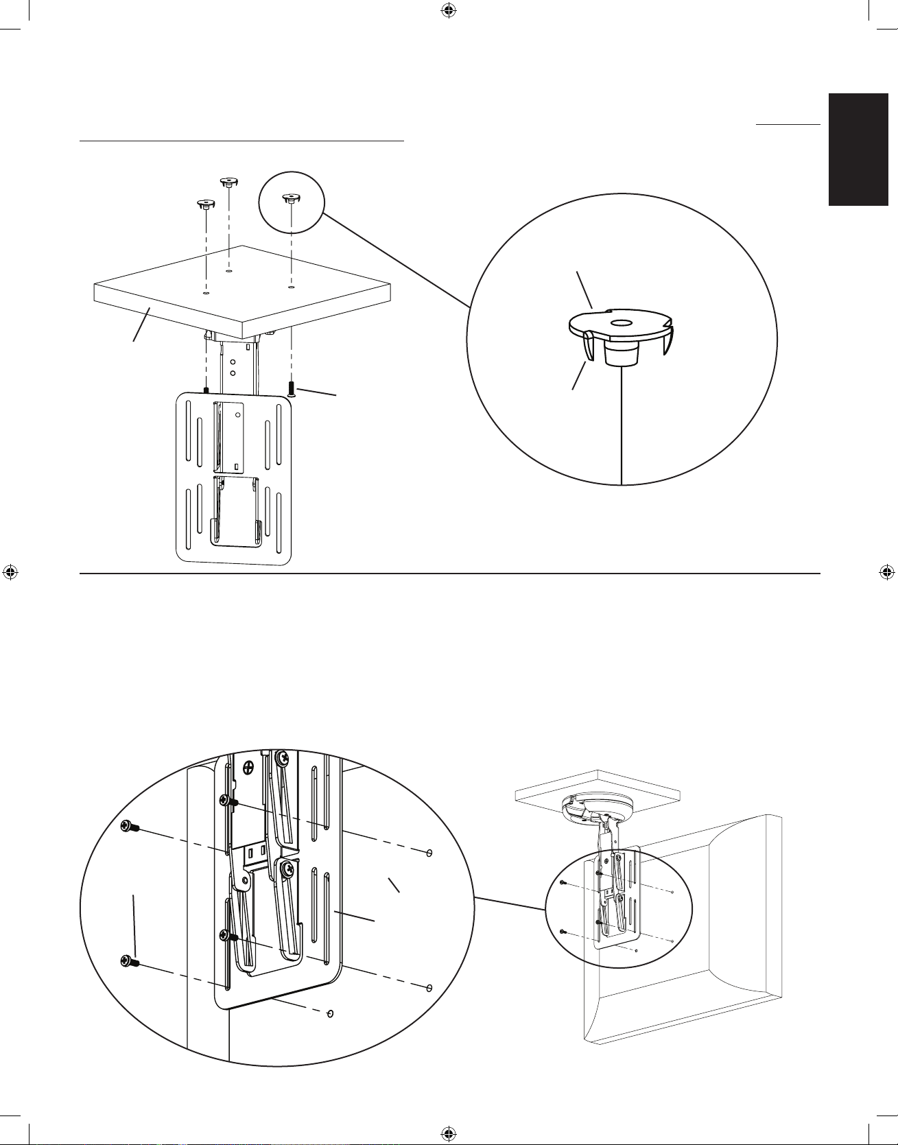
Step 3: Secure Mount Assembly to cabinet
Using the 10-24 x 5/8 Bolts (c) and the T - Nuts (b) secure the Mount Assembly to the cabinet. See Diagram 3 for assistance. Note: Make
sure the spikes on the T - Nuts is facing toward the cabinet.
Diagram 3
Detailed View
b
cabinet
c spike
Step 4: Attach at panel display to mounting plate
Make sure no power is supplied to the display before mounting the display!
Warning: Watch for pinch points. Do not put your ngers or cables between movable parts.
Once the Mount Assembly (a) is secured to the cabinet, align the appropriate slots in the mounting plate with the four mounting holes of
your LCD display. Use either four M4 x 10 mm Bolts (d) or four M4 x 20 mm Bolts (e) with four .5 inch Spacers (f). Diagram 4a below
shows the M4 x 10 mm Bolts being used. Diagram 4b on the next page shows the M4 x 20 mm Bolts with the .5 inch Spacers.
Detailed View
Diagram 4a
LCD panel
d
mounting plate
ENGLISH
Step 4 (cont)
The .5 inch Spacers (f) should only be used if there is an obstruction or the hole pattern is physically recessed on the back of the LCD
panel. See Diagram 4b for assistance.
Detailed View Diagram 4b
e
mounting plate
f
LCD Panel
Step 5: Adjusting the screen height.
Using a Phillips screw driver, slightly loosen the Bolts (d,e) that secure the LCD panel to the mounting plate. Adjust the LCD panel to
the desired height. Tighten the Bolts (d,e) to secure the LCD panel to the mounting plate. See Diagram 5 for assistance.
Diagram 5
d,e
mounting plate
ENGLISH
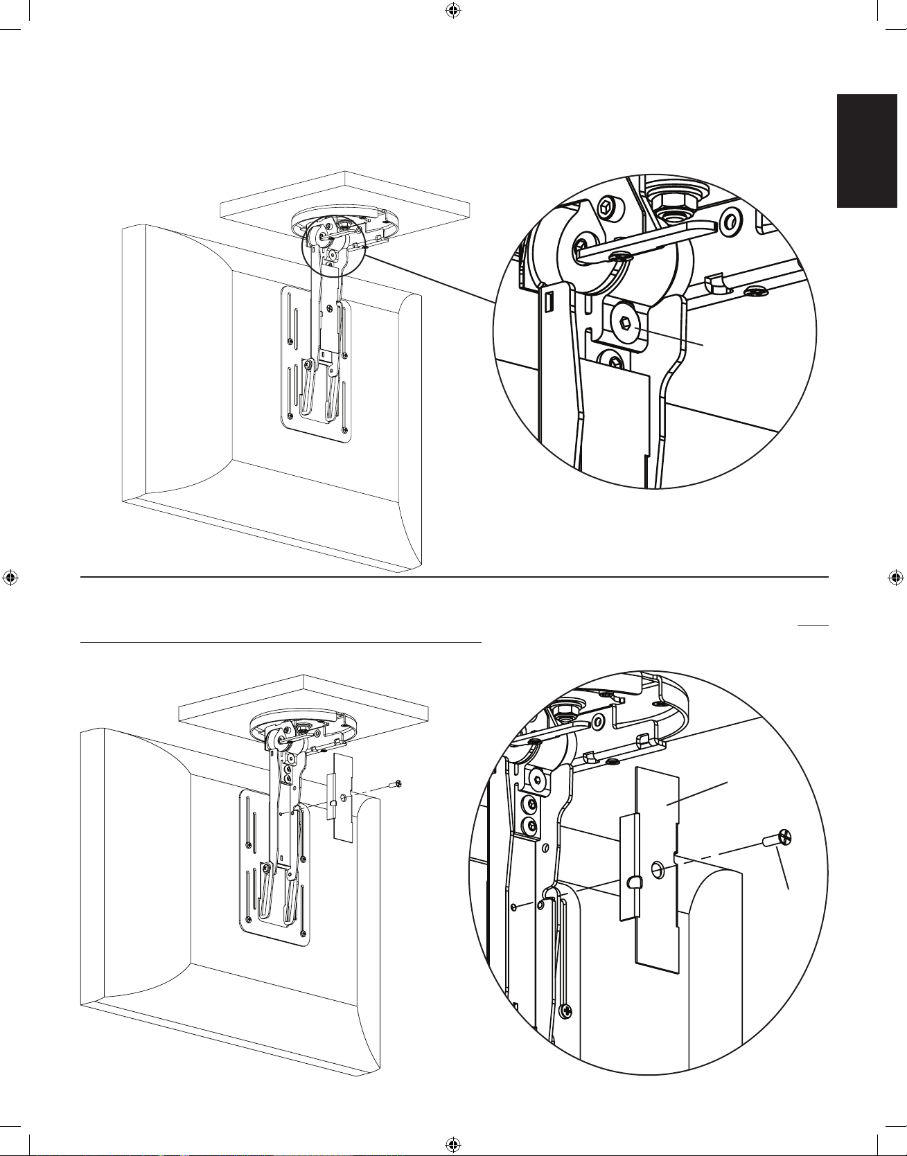
Step 6: Adjust tension of Mount Assembly
The tension of the Mount Assembly (a) can be adjusted by simply tightening or loosening the tension bolt labeled in Diagram 6 with the
provided Allen Key (h).
Diagram 6 Detailed View
tension bolt
Step 7: Remove Cable Cover
Using a Phillips screw driver, loosen the screw in the center of the cable cover and remove cover. See Diagram 7 for assistance. Note:
You will re-install the cable cover once cable management is completed.
Diagram 7 Detailed View
cable cover
screw
ENGLISH
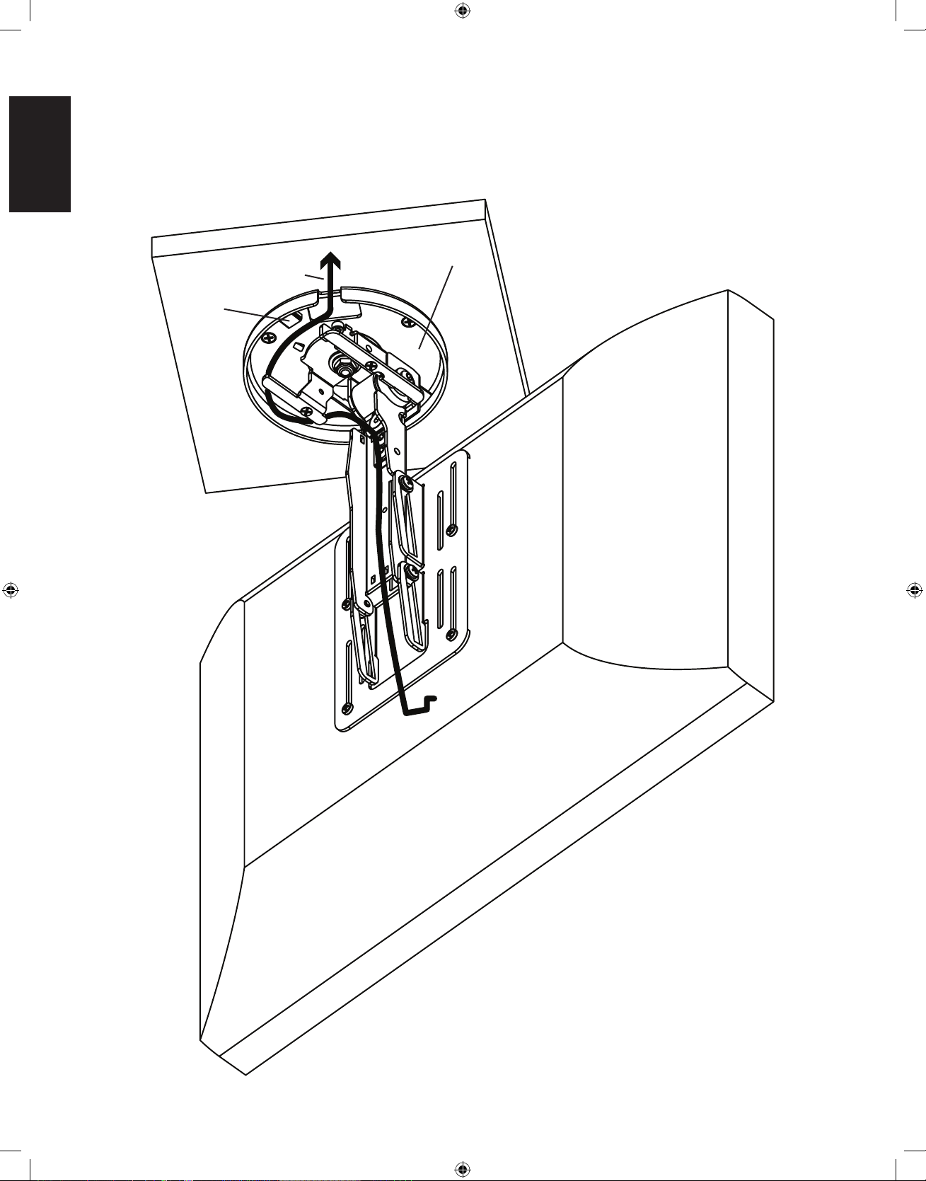
Step 8: Cable Management (±35° swivel)
Swivel the Mount Assembly (a) 35° either left or right. You will run the cables in the opposite direction. You can attach the Cable Ties
(g) in locations marked in Diagram 8 below.
Diagram 8
a
cable path
cable tie
holder
ENGLISH
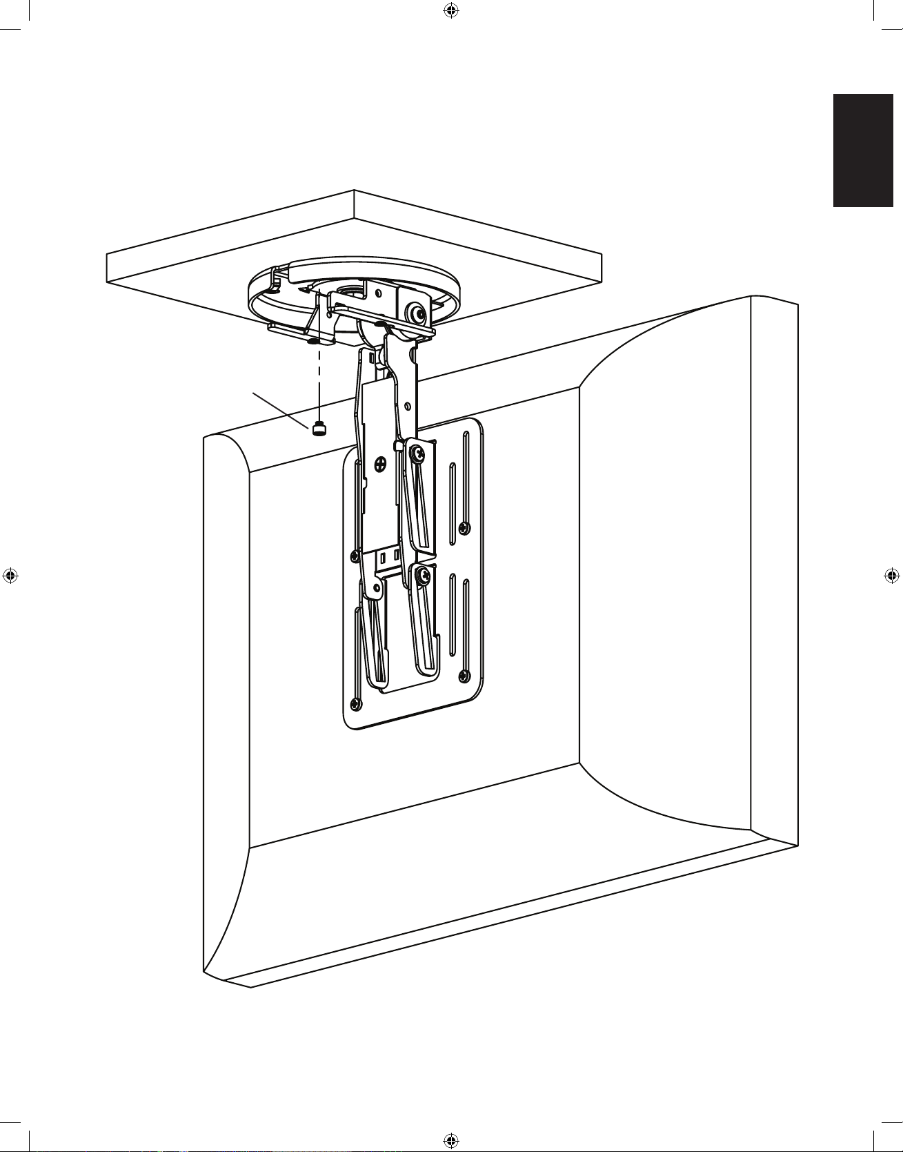
Step 9: Remove Degree Stop
Using provided Allen Wrench (h), remove the 35 degree stop. See Diagram 9 for assistance.
Diagram 9
35 degree stop

ENGLISH
Step 10: Cable management (±110°)
Swivel the Mount Assembly (a) 110° either left or right. You will run the cables in the opposite direction. Cables must be wrapped a
complete 360° inside the base of the Mount Assembly. You can attach the Cable Ties (g) in locations marked in Diagram 8 below.
Diagram 10
cable tie
holder
a cable path

ESPAÑOL
Instrucciones de ensamblaje del modelo: VMUC1
Gracias por elegir el soporte para instalación debajo de un armario Vision Mount de Sanus
Systems. El modelo ha sido diseñado para soportar una pantalla plana de cristal líquido de
17 pulgadas con un peso de hasta 6,8 kg.
Advertencia de seguridad: Si no entiende estas instrucciones o si tiene alguna duda
con respecto a la seguridad de la instalación, llame a un contratista calificado o llámenos
al (800) 359-5520 (en EE.UU.) o al 31 (0) 20 570-8938 (en Europa). También nos puede
visitar en nuestro sitio www.sanus.com. Revise cuidadosamente para asegurarse de que no
falta ninguna pieza ni están defectuosas. Nuestros representantes del servicio de atención al
cliente podrán ayudarle oportunamente con cualquier duda que tenga sobre la instalación o
con respecto a las piezas que falten o estén dañadas. Las piezas de repuesto para los productos
comprados a través de un distribuidor autorizado se enviarán directamente a usted. Nunca use
piezas defectuosas. La instalación incorrecta podría ocasionar daños o lesiones graves.
No
utilice este producto para otro fin que no sea el explícitamente especificado por Sanus Systems.
Sanus Systems no será responsable por daños ni lesiones debidos al montaje, ensamblaje o uso
incorrectos. Llame a Sanus Systems antes de devolver los productos al punto de compra.
Herramientas necesarias: Destornillador Phillips, taladro, broca de 1/4 pulg.
Piezas y tornillería suministrada: Algunas piezas no se muestran a tamaño real*
(3) Tuercas en T - b (3) Perno 10-24 x 5/8 - c
(1) Conjunto de soporte - a
(4) Perno M4 x 10 mm - d (4) Perno M4 x 20 mm - e
(4) Espaciador de 0,5 pulg. - f
(4) Sujetacables - g (1) Llave allen - h
Sanus Systems 2221 Hwy 36 West, Saint Paul, MN 55113 (6901-300074 <02>)
Servicio de atención al cliente: (800) 359-5520. Vea los productos complementarios de Sanus en el sitio www.sanus.com

ESPAÑOL
Utilice la base del conjunto de soporte
(a) como una plantilla para marcar
tres agujeros en la ubicación deseada
del armario.
Taladre tres agujeros de 0,6 cm en los
puntos marcados.
Ver el diagrama dimensional a la
derecha para más ayuda.
Diagrama dimensional
1,89 1,89
3,28
Paso 1: Retirada de la cubierta
Con un destornillador Phillips, afloje los dos pernos de cabeza plana de la cubierta y retírelos de la placa de montaje. Ver diagrama 1
como ayuda. Tendrá que volver a instalar la cubierta una vez que termine la instalación de los cables.
Diagrama 1
a
placa de montaje
cubierta pernos de cabeza plana
Paso 2: Preparación de la supercie de montaje

ESPAÑOL
Paso 3: Fijación del conjunto de soporte en el armario
Con los pernos de 10-24 x 5/8 (c) y las tuercas en T - (b), asegure el conjunto de soporte en el armario. Ver diagrama 3 como ayuda. Nota:
Asegúrese de que los dientes de las tuercas en T queden hacia el armario.
Diagrama 3
Vista detallada
b
armario
c diente
Paso 4: Conexión de la pantalla a la placa de montaje
¡Asegúrese de que no entre corriente a la pantalla antes de montarla!
Advertencia: Tenga cuidado con los puntos de aplastamiento. No ponga los dedos ni los cables entre las piezas móviles.
Una vez que el soporte (a) está bien asegurado al armario, alinee las ranuras correspondientes de la placa de montaje con los cuatro
agujeros de montaje de la pantalla plana. Utilice cuatro pernos M4 x 10 mm (d) o cuatro pernos M4 x 20 mm (e) con cuatro espaciadores
de 0,5 pulg. (f). El diagrama 4a mostrado más abajo muestra la instalación con pernos M4 x 10 mm. El diagrama 4b en la página
siguiente muestra la instalación con pernos M4 x 20 mm y espaciadores de 0,5 pulg.
Vista detallada
Diagrama 4a
pantalla de
cristal líquido
d
placa de montaje

ESPAÑOL
Paso 4 (continuación)
Los espaciadores de 0,5 pulg. (f) deben utilizarse sólo si hubiera una obstrucción o si los agujeros estuvieran físicamente empotrados en
la parte posterior de la pantalla de cristal líquido. Ver diagrama 4b como ayuda.
Vista detallada Diagrama 4b
e
placa de montaje
f
pantalla de
cristal líquido
Paso 5: Ajuste de altura de la pantalla.
Con un destornillador Phillips, afloje levemente los pernos (d,e) que aseguran la pantalla a la placa de montaje. Ajuste la pantalla a la
altura deseada. Apriete los pernos (d,e) para asegurar la pantalla en la placa de montaje. Ver diagrama 5 como ayuda.
Diagrama 5
d,e
placa de montaje

ESPAÑOL
Paso 6: Ajuste de la tensión del conjunto de soporte
Se puede ajustar la tensión del conjunto de soporte (a) apretando o aflojando el perno tensor identificado en el diagrama 6 con la llave
allen suministrada (h).
Diagrama 6 Vista detallada
perno tensor
Paso 7: Retirada de la cubierta de los cables
Con un destornillador Phillips, afloje el tornillo central de la cubierta de los cables y extraiga la cubierta. Ver diagrama 7 como ayuda.
Nota: Tendrá que volver a instalar la cubierta una vez que termine con la instalación de los cables.
Diagrama 7 Vista detallada
cubierta
de los cables
tornillo

ESPAÑOL
Paso 8: Instalación de cables (giro de ±35°)
Gire el soporte (a) 35° hacia la izquierda o a la derecha. Corra los cables en el sentido contrario. Puede instalar los sujetacables (g) en los
puntos indicados en el diagrama 8 mostrado más abajo.
Diagrama 8
a
paso de cables
soporte del
sujetacables

ESPAÑOL
Paso 9: Retirada del tope de giro
Con la llave allen (h) suministrada, retire el tope de giro de 35 grados. Ver diagrama 9 como ayuda.
Diagrama 9
tope de giro de 35 grados

ESPAÑOL
Paso 10: Instalación de cables (±110°)
Gire el soporte (a) 110° hacia la izquierda o a la derecha. Corra los cables en el sentido contrario. Los cables deben enrollarse en 360°
dentro de la base del conjunto de soporte. Instale los sujetacables (g) en los puntos indicados en el diagrama 10 mostrado más abajo.
Diagrama 10
soporte del
sujetacables
a paso de
cables

FRANÇAIS
Instructions d’assemblage pour le modèle : VMUC1
Nous vous remercions d’avoir choisi un montant à glisser sous une armoire VisionMount de Sanus
Systems. Le VMUC1 est conçu pour soutenir des téléviseurs LCD à panneau plat allant jusqu’à
17 pouces et pesant jusqu’à 6,8 kg.
Avertissement relatif à la sécurité : Si vous ne comprenez pas ces instructions ou si vous
avez un doute quant à la sécurité de cette installation, veuillez faire appel à un technicien qualifié ou
communiquez avec Sanus en composant le 1-800-359-5520 (aux É.-U.), ou le 31 (0) 20 5708938 (pour
l’Europe). Vous pouvez également visiter notre site web au www.sanus.com. Vérifiez soigneusement
qu’il n’y a aucune pièce manquante ou défectueuse. Les représentants de notre service à la clientèle
peuvent répondre rapidement à toute question concernant l’installation ou les pièces manquantes
ou endommagées. Les pièces de rechange de produits achetés auprès de distributeurs agréés vous
seront livrées directement. N’utilisez jamais de pièces défectueuses. Une installation incorrecte
peut entraîner des dommages ou des blessures graves. Ce produit ne doit être utilisé que pour des
usages explicitement spécifiés par Sanus Systems. Sanus Systems ne pourra être tenu responsable
de dommages ou de blessures dus à un montage incorrect, à un assemblage incorrect ou à un usage
incorrect. Veuillez contacter Sanus Systems avant de retourner les produits au point de vente.
Outils nécessaires : Tournevis cruciforme, perceuse, mèche de 1/4 pouce
Pièces et matériel fournis : Certaines pièces ne sont pas illustrées grandeur réelle*
(3) Écrous en T - b (3) Boulon 10/-24 5 x 8 - c
(1) Support d’écran - a
(4) Boulon M4 x 10 mm - d (4) Boulon M4 x 20 mm - e
(4) Entretoise de 0,5 pouce - f
(4) Serre-câble - g (1) Clé Allen - h
Sanus Systems 2221 Hwy 36 West, Saint Paul, MN 55113 USA (6901-300074 <02>)
Service à la clientèle : 800.359.5520. Pour les produits Sanus complémentaires, consultez le www.sanus.com

FRANÇAIS
Plan dimensionnel
1,89 1,89
3,28
Utilisez la base du support d’écran (a)
comme modèle pour marquer trois trous
dans l’armoire à l’emplacement désiré.
Percez trois trous de 0,6 cm aux endroits
marqués.
Reportez-vous au plan dimensionnel à
droite si vous avez besoin d’aide.
Étape 1 : Retrait du couvercle
À l’aide d’un tournevis cruciforme, desserrez les deux boulons à tête plate du couvercle et glissez-le vers le bas et éloignez-le de
la plaque de montage. Reportez-vous au schéma 1 si vous avez besoin d’aide. Vous pourrez réinstaller le couvercle une fois que la
manipulation des câbles sera terminée.
Schéma 1
a
plaque de montage
couvercle boulons à tête plate
Étape 2 : Préparation de la surface de montage

FRANÇAIS
Étape 3 : Fixation du support d’écran à l’armoire
À l’aide des boulons 10-24 x 5/8 (c) et des écrous en T (b), fixez le support d’écran à l’armoire. Reportez-vous au schéma 3 si vous avez
besoin d’aide. Remarque : Assurez-vous que les crampons sur les écrous en T sont face à l’armoire.
Schéma 3
Vue détaillée
b
armoire
c crampon
Étape 4 : Fixation de l’écran à panneau plat à la plaque de montage
Assurez-vous que l’écran n’est pas sous tension avant de l’installer au montant!
Avertissement : Faites attention aux points de pincement. Ne mettez pas les mains ou les doigts entre les pièces mobiles.
Une fois que le support d’écran (a) est fixé à l’armoire, alignez les fentes appropriées de la plaque de montage avec les quatre trous de
montage de votre écran LCD. Utilisez quatre boulons M4 x 10 mm (d) ou quatre boulons M4 x 20 mm (e) avec quatre entretoises de
0,5 pouce (f). Le schéma 4a ci-dessous illustre les boulons M4 x 10 mm utilisés. Le schéma 4b à la page suivante illustre les boulons
M4 x 20 mm avec les entretoises de 0,5 pouce.
Vue détaillée
Schéma 4a
panneau LCD
d
plaque de montage

FRANÇAIS
Étape 4 (suite)
Les entretoises de 0,5 pouce (f) devraient seulement être utilisées s’il y a une obstruction ou si le trou à l’arrière du panneau LCD est en
retrait. Reportez-vous au schéma 4b si vous avez besoin d’aide.
Vue détaillée Schéma 4b
e
plaque de montage
f
panneau LCD
Étape 5 : Réglage de la hauteur d’écran.
À l’aide d’un tournevis cruciforme, desserez légèrement les boulons (d,e) qui fixent le panneau LCD à la plaque de montage. Réglez
le panneau LCD à la hauteur désirée. Serrez les boulons (d,e) pour fixer le panneau LCD à la plaque de montage. Reportez-vous au
schéma 5 si vous avez besoin d’aide.
Schéma 5
d,e
plaque de montage

FRANÇAIS
Étape 6 : Réglage de la tension du support d’écran
La tension du support d’écran (a) peut être ajustée en serrant ou en desserrant simplement le boulon de tension étiqueté au schéma 6 à
l’aide de la clé Allen fournie (h).
Schéma 6 Vue détaillée
boulon de tension
Étape 7 : Retrait du couvercle de câble
À l’aide d’un tournevis cruciforme, desserrez la vis au centre du couvercle de câble et retirez le couvercle. Reportez-vous au schéma 7 si
vous avez besoin d’aide. Remarque : Vous pourrez réinstaller le couvercle de câble une fois que la manipulation des câbles sera terminée.
Schéma 7 Vue détaillée
couvercle du câble
vis

FRANÇAIS
Étape 8 : Manipulation du câble (pivotement ±35°)
Faites pivoter le support d’écran (a) de 35° vers la gauche ou vers la droite. Vous acheminerez les câbles dans la direction opposée. Vous
pouvez fixer les serre-câble (g) aux endroits marqués au schéma 8 ci-dessous.
Schéma 8
a
acheminement du câble
support de
serre-câble

FRANÇAIS
Étape 9 : Retrait de la butée de pivot
À l’aide de la clé Allen fournie (h), retirez la butée de pivot de 35 degrés. Reportez-vous au schéma 9 si vous avez besoin d’aide.
Schéma 9
butée de pivot de 35 degrés

FRANÇAIS
Étape 10 : Manipulation du câble (pivotement ±110°)
Faites pivoter le support d’écran (a) de 110° vers la gauche ou vers la droite. Vous acheminerez les câbles dans la direction opposée. Les
câbles doivent être enroulés pour faire un tour complet de 360° à l’intérieur du support d’écran. Vous pouvez fixer les serre-câble (g) aux
endroits marqués au schéma 10 ci-dessous.
Schéma 10
support de serre-câble
a
acheminement
du câble

 Loading...