

Page 1
SERVICE & OPERATING MANUAL
II 2GD T5
Original Instructions
Model ST1½ Type 4
See pages 18 & 19
for ATEX ratings
Model ST40 Type 4
Table of Contents
Engineering Data, Temperature Limitations and Performance Curve ................... 1
Explanation of Pump Nomenclature ...................................................................... 2
Dimensions ............................................................................................................ 3
Principle of Operation ............................................................................................ 4
Installation Guide ................................................................................................... 5
Filling the Driver Chambers with Fluid ................................................................... 6
Chamber Porting, Air Supply, Operation ................................................................ 7
Air Exhaust, Freezing or Icing of Exhaust ............................................................. 7
Maintenance After Use, Maintenance Note ........................................................... 7
Check Valve Servicing ........................................................................................... 8
Diaphragm Servicing ............................................................................................. 8
Air Valve Lubrication .............................................................................................. 9
®
:
ESADS+Plus
Externally Serviceable Air Distribution System ................................9
Pilot Valve ............................................................................................................ 10
Pilot Valve Actuator .............................................................................................. 10
Warranty .............................................................................................................. 10
Important Safety Information ............................................................................... 11
Grounding The Pump .......................................................................................... 12
Material Codes .................................................................................................... 13
Composite Repair Parts List ........................................................................... 14-15
Composite Repair Drawing.................................................................................. 16
CE Declaration of Conformity - Machinery .......................................................... 17
CE Declaration fo Conformity - ATEX .................................................................. 18
Explanation of ATEX Certication ........................................................................ 19
hdb15dl7sm-rev0614
Warren Rupp, Inc. • A Unit of IDEX Corporation • 800 N. Main St., Manseld, Ohio 44902 USA
Telephone (419) 524-8388 • Fax (419) 522-7867 • warrenrupp.com
©Copyright 2014 Warren Rupp, Inc. All rights reserved.
Page 2

Page 3
Quality System
II 2GD T5
ISO9001 Certied
Environmental
Management System
ISO14001 Certied
See page 18 & 19
for ATEX ratings
Containment Duty
ST1½ Type 4
ST40 Type 4
Air-Operated
Double Diaphragm Pump
ENGINEERING, PERFORMANCE
& CONSTRUCTION DATA
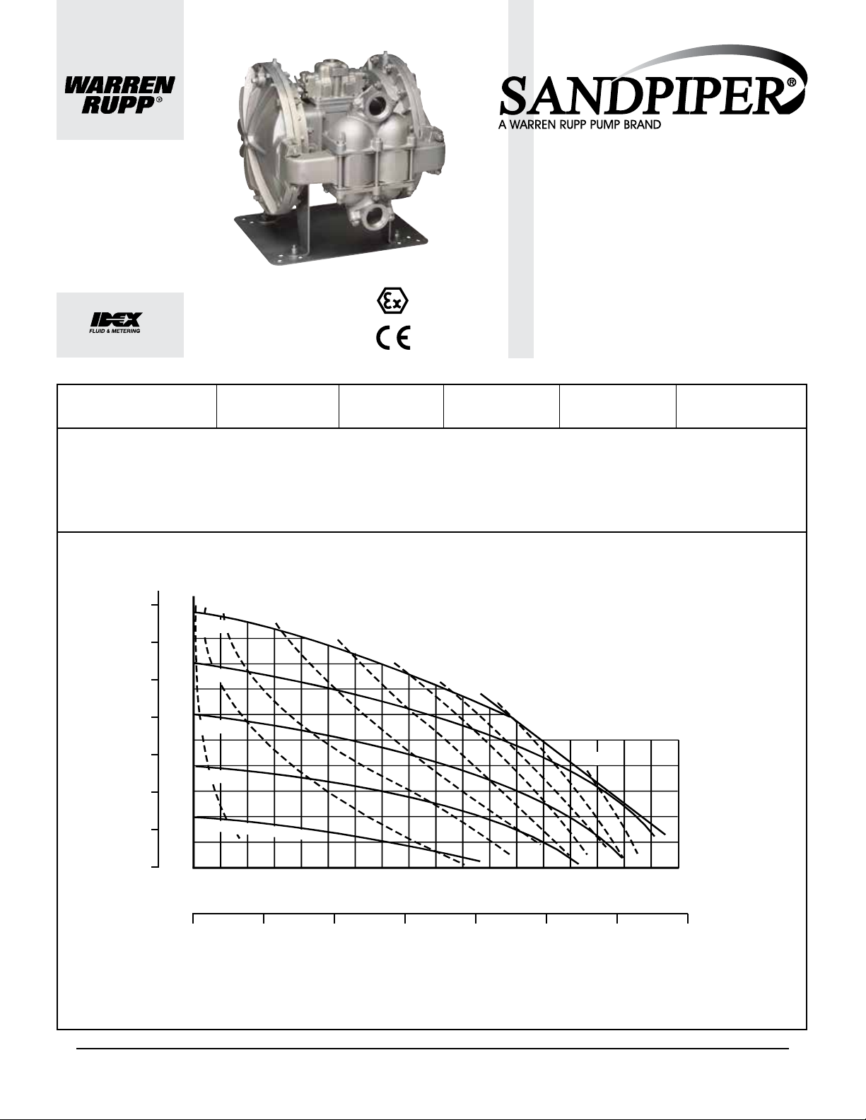
INTAKE/DISCHARGE PIPE SIZE
ST1½: 1½ (37.5mm) NPT (F)
ST40: 1½ (37.5MM) BSP (F)(Tapered)
CAPACITY AIR VALVE SOLIDS-HANDLING HEADS UP TO
0 to 90 gallons per minute
(0 to 340 liters per minute)
No-lube, no-stall
design
Occasional solids only.
Up to ¼ in. (6.3mm)
125 psi or 289 ft. of water
(8.8 Kg/cm
2
or 88 meters)
DISPLACEMENT/STROKE
.37 Gallon / 1.29 liter
SANDPIPER® Containment Duty Pumps: Sealless Safety
This pump is part of the Containment Duty Pumps. It is specially tted with PTFE diaphragms as well as elastomeric or elastomeric/PTFE driver diaphragms. The liquid-lled
spill chambers provide an additional chemically-resistant barrier, should a pumping diaphragm fail. The Spill Containment design gives the pump user advanced warning of
diaphragm failure, before pumpage can damage the air valve or be released into the work environment. Three optional leak detectors available for this model:
• Mechanical VIP Leak Detector* 031-025-000 • Electronic Leak Detector* (115V) 032-043-000 • Electronic Leak Detector* (220V) 032-043-000
The Containment Duty pumps offer many different levels of materials and spill monitoring devices designed to t a variety of applications and budgets.
* Leak Detectors are not ATEX Compliant
BAR
7
100
90
6
80
5
70
60
4
50
HEAD
3
40
30
2
PSI
10(17)
100 PSI
80 PSI
60 PSI
40 PSI
AIR CONSUMPTION
SCFM (M
20(34)
30(51)
40(68)
3
/hr)
50(85)
MODEL ST1½/ST40 Performance Curve
Performance based on the following: elastomer fitted pump, flooded suction,
water at ambient conditions. The use of other materials and varying hydraulic
60(102)
70(119)
conditions may result in deviations in excess of 5%.
80(136)
90(152.9)
20
1
20 PSI Air Inlet Pressure
10
0
0
0
10 20
30 40
50
60 70 80
90
US Gallons per minute
0 50 100 150 200 250 300 350
Liters per minute
CAPACITY
SANDPIPER® pumps are designed to be powered only by compressed air.
st15dl4sm-rev0614 Models ST1½, ST40 Page 1
Page 4
Explanation of Pump Nomenclature, ST1½ & ST40
II 2GD T5
II 2GD T5
ST1½ -A: 1½"
(37.5mm)
NPT(F)
ST40-A: 1½"
(37.5mm)
BSP(F)
0 to 90 gallons per minute
(0 to 340 liters per minute)
Occasional solids only.
up to ¼"
(6.3mm)
125 psi or 289 ft. of water
(8.8 Kg/cm2 or 88 meters)
No-lube, non-stall
design.
®
pumps are designed to be powered only by compressed air)
Temperature Limit: 212
F -
100 C
MAXIMUM
Performance based on water at
ambient temperature. Average
displacement per pump stroke:
1.14 liters.
Performance based on water at
ambient temperature. Average
displacement per pump stroke:
0.30 gallon.
ST1 -A Type 4
ST40-A Type 4
1
2
Quality System
ISO9001 Certified
Environmental
Management System
ISO14001 Certified
®
(SANDPIPER
SANDPIPER
®
Models SANDPIPER® Models
Containment Duty
SANDPIPER® Containment Duty Pumps: Sealless Safety
This pump is part of the Containment Duty Pumps. It is specially fitted with PTFE diaphragms as well as elastomeric or elastomeric/PTFE driver diaphragms. The liquid-filled spill chambers
provide an additional chemically-resistant barrier, should a pumpIng diaphragm fail. The Spill Containment design gives the pump user advanced warning of diaphragm failure, before
pumpage can damage the air valve or be released into the work environment. Three optional leak detectors available for this model:
• Mechanical VIP Leak Detector 031-025-000 • Electronic Leak Detector (115V) 032-043-000 • Electronic Leak Detector (220V) 032-043-000
The Containment Duty pumps offer many different levels of materials and spill monitor ing devices designed to fit a variety of applications and budgets.
I M2 c T5
II 2GD T5
MATERIALS OF CONSTRUCTION
To order a pump or replacement parts, rst enter the Model Number ST15, or ST40, followed by the Type Designation listed below in the far left column.
Type 4
SGI-4-A X AL356T6 AL356T6 AL356T6 AL356T6 316SS AL380DC AL356T6 416SS 316SS 304SS T/I T T T 99
SGN-4-A X AL356T6 AL356T6 AL356T6 AL356T6 316SS AL380DC AL356T6 416SS 316SS 304SS T/N T T T 99
SGV-4-A X AL356T6 AL356T6 AL356T6 AL356T6 316SS AL380DC AL356T6 416SS 316SS 304SS T/V T T T 99
SGI-4-SS X WR-S WR-S AL356T6 AL356T6 316SS AL380DC AL356T6 416SS 316SS 304SS T/I T T T 146
SGN-4-SS X WR-S WR-S AL356T6 AL356T6 316SS AL380DC AL356T6 416SS 316SS 304SS T/N T T T 146
SGV-4-SS X WR-S WR-S AL356T6 AL356T6 316SS AL380DC AL356T6 416SS 316SS 304SS T/V T T T 146
SGI-4-HC X WR-C WR-C AL356T6 AL356T6 316SS AL380DC AL356T6 416SS 316SS 304SS T/I T T T 146
SGN-4-HC X WR-C WR-C AL356T6 AL356T6 316SS AL380DC AL356T6 416SS 316SS 304SS T/N T T T 146
SGV-4-HC X WR-C WR-C AL356T6 AL356T6 316SS AL380DC AL356T6 416SS 316SS 304SS T/V T T T 146
SGI-4-II X CI CI CI DI 316SS CI CI 416SS 316SS 304SS T/I T T T 212
SGN-4-II X CI CI CI DI 316SS CI CI 416SS 316SS 304SS T/N T T T 212
SGV-4-II X C
SGN-4-HI X CI DI 316SS CI CI 416SS 316SS 304SS T/N T T T 212
SGV-4-HI X WR-C
SGN-4-SI X WR-S WR-S CI DI 316SS CI CI 416SS 316SS 304SS T/N T T T 209
SGV-4-SI X WR-S WR-S CI DI 316SS CI CI 416SS 316SS 304SS T/V T T T 209
Kit available to convert to top or bottom porting.
SPST1½A-REV0807
Porting
Manifold
Manifold Outer
Side
Chamber
Driver
Chamber
Chamber
Inner
Outer
Diaphragm
Plate
Inner
Diaphragm
Plate
Intermediate
Housing
Diaphragm
I
CI CI DI 316SS CI CI 416SS 316SS 304SS T/V T T T 212
WR-C
WR-C
WR-C
AL = Aluminum
CI = Cast Iron
DC = Die Cast
CI DI 316SS CI CI 416SS 316SS 304SS T/V T T T 212
DI = Ductile Iron
SS = Stainless Steel
T = PTFE
T/I = PTFE Diaphragm/EDPM Driver
®
is a registered tradenames of E.I. du Pont.
Viton
II 1 G c T5
II 3/1 G c T5
II 1 D c T100oC
I M1 c
I M2 c
Models equipped with Cast Iron, Stainless
Steel, or Alloy C wetted parts, and Cast Iron
midsection parts. See page 6 for ATEX
Explanation of EC-Type Certicate.
Hard-
ware
Diaphragm
Rod
Valve
Seat
Ball
Valve
Material
T/N = PTFE Diaphragm/Neoprene Driver
T/V = PTFE Diaphragm/Viton
WR-S = Warren Rupp Alloy Type 316 Stainless Steel
WR-C = Warren Rupp Alloy "C" (Hastelloy C equivalent)
®Warren Rupp and SANDPIPER are registered tradenames of Warren Rupp, Inc.
®
Driver
II 2 G c T5
II 3/2 G c T5
II 2 D c T100oC
All models, including pumps equipped with
Aluminum wetted and midsection parts.
See page 6 for ATEX Explanation of
Type Examination Certicate.
Seat
Gasket
Manifold
Gasket
Sealing
Rings
Shipping
Wt.(lbs)
Maximum and Minimum Temperatures are the limits for which
these materials can be operated. Temperatures coupled with
pressure affect the longevity of diaphragm pump components.
Maximum life should not be expected at the extreme limits of
the temperature ranges.
Operating Temperatures
Materials
EPDM Shows very good water and chemical resistance. Has poor resistance to oil and solvents, but is fair in
ketones and alcohols.
NEOPRENE All purpose. Resistant to vegetable oils. Generally not affected by moderate chemicals, fats,
greases and many oils and solvents. Generally attacked by strong oxidizing acids, ketones, esters, nitro
hydrocarbons and chlorinated aromatic hydrocarbons.
PTFE Chemically inert, virtually impervious. Very few chemicals are known to react chemically with
PTFE: molten alkali metals, turbulent liquid or gaseous uorine and a few uoro-chemicals such as
chlorine triuoride or oxygen diuoride which readily liberate free uorine at elevated temperatures.
FKM (Fluorocarbon) shows good resistance to a wide range of oils and solvents; especially all aliphatic,
aromatic and halogenated hydrocarbons, acids, animal and vegetable oils. Hot water or hot aqueous solu
tions (over 70°F) will attack FKM.
CF-8M Stainless Steel equal to or exceeding ASTM specication A743 for corrosion resistant iron chro-
‡
mium, iron chromium nickel, and nickel based alloy castings for general applications. Commonly referred
to as 316 Stainless Steel in the pump industry.
ALLOY C CW-12MW equal to or exceeding ASTM A494 specication for nickel and nickel alloy castings.
For specic applications, always consult “Chemical Resistance Chart" Technical Bulletin
Maximum Minimum
280°F -40°F
138°C -40°C
200°F -10°F
93°C -23°C
220°F -35°F
104°C -37°C
350°F -40°F
-
177°C -40°C
st15dl4sm-rev0614 Models ST1½, ST40 Page 2
Page 5
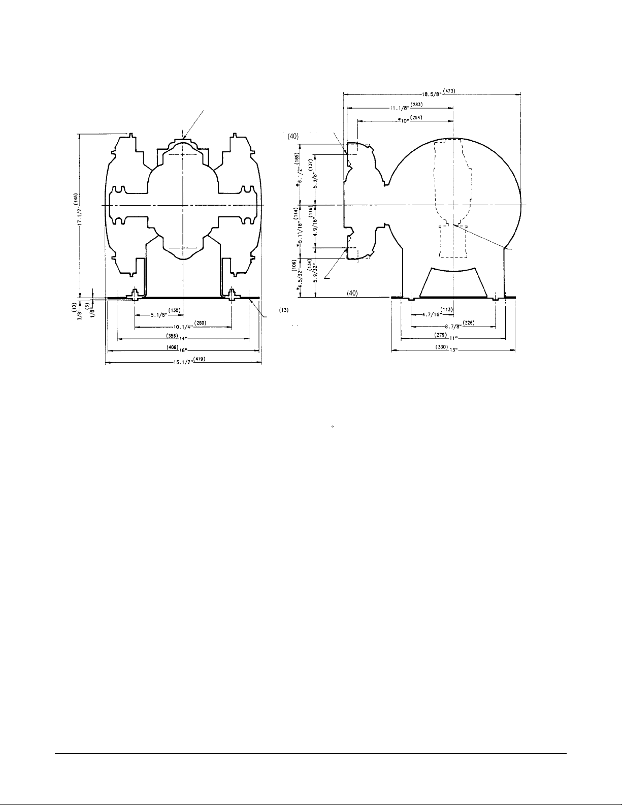
Dimensions: ST1½ & ST40
AIR INLET
3/4” NPT(F)
PUMP TO BASE
UNIT OF MOUNTING HOLES
DISCHARGE PORT
1 1/2” NPT (F)
1 1/2” BSP (F) TAPERED
1/2” DIA. MOUNTING HOLES
TYP. (8) PLACES
TAPERED
SUCTION PORT
1 1/2” NPT (F)
1 1/2” BSP (F) TAPERED
TAPERED
PUMP TO BASE
UNIT OF MOUNTING HOLES
AIR EXHAUST
3/4” NPT(F)
* INDICATES DIMENSIONS WITH SUCTION AND DISCHARGE
PORTS ROTATED 180° TO A VERTICAL POSITION
DIMENSIONAL OUTLINES AVAILABLE SHOWING OPTIONAL TOP AND BOTTOM PORTING
DIMENSIONS WITH SUCTION AND DISCHARGE PORTS ROTATED 90 TO VERTICAL POSITION (SHOWN WITH DOTTED LINES).
*
Model ST1½
-A features NPT threaded connections.
Model ST40-A features British Standard Pipe (BSP) tapered threaded connections.
st15dl4sm-rev0614 Models ST1½, ST40 Page 3
Page 6

SERVICE & OPERATING MANUAL
II 2GD T5
Model ST1½ Type 4
See pages 18 & 19
for ATEX ratings
PLEASE NOTE!
The photos shown in this manual are for general instruction only. Your specic model
may not be shown. Always refer to the parts list and exploded view drawing for your
specic model when installing, disassembling or servicing your pump.
PRINCIPLE OF OPERATION
All Warren Rupp SANDPlPER pumps, including this Containment Duty SANDPlPER
pump, operate on the same basic principle. They are designed to be powered by compressed
air only which alternately pressurizes the inner side of one diaphragm chamber while
simultaneously exhausting the other inner chamber. The diaphragms are connected by
a common rod; when the inner side of one diaphragm chamber is pressurized, moving
the diaphragm outward on a discharge stroke, the opposite diaphragm is pulled inward
on a suction stroke.
Alternate pressurizing and exhausting of the diaphragm chamber is accomplished
with an externally mounted pilot operated, four way, spool type, air distribution valve.
When the spool is at one end of the valve body, inlet air pressure is connected to one
diaphragm chamber while the other diaphragm chamber is exhausting. When the spool
is moved to the opposite end of the valve body, the porting of chambers is reversed. The
air distribution valve spool is moved from one end position to the other in the valve body
by an internal pilot valve which alternately pressurizes one end of the air distribution valve
spool while simultaneously exhausting the other. The pilot valve is positively shifted at
each end of the diaphragm stroke by the diaphragm plate contacting the end of the pilot
valve spool. This pushes it into position to shift the air distribution valve.
In all SANDPlPER pumps, this reciprocating diaphragm movement creates an alternating
suction and discharge action in the outer diaphragm chamber and the pumped material. A
manifold with a suction and discharge check valve for each chamber serves as a common
inlet and outlet for the pump.
This Containment Duty SANDPlPER unit differs from other SANDPIPER units only in
that it utilizes four (4) diaphragms instead of two (2). Two rod-connected diaphragms are
the driver diaphragms. The other two (outermost) diaphragms are the actual pumping
diaphragms. Each driver diaphragm (of neoprene or other elastomer), and the pumping
diaphragm (of PTFE), are separated by a chamber lled with liquid which transmits the
reciprocating motion of the driver diaphragm to the pumping diaphragm. The PTFE pumping
diaphragms, in turn, create the alternating suction and discharge action in the outer
diaphragm chambers, and are the only diaphragms in contact with liquid being pumped.
Model ST40 Type 4
Original Instructions
INSTALLATION PROCEDURES
CAUTION: This pump should not be applied in pumping applications where the driver
liquid coming in contact with the pumped liquid would create a hazardous condition.
This contact will occur if a PTFE pumping diaphragm fails since this diaphragm normally
separates the two liquids. Also note that care must be taken to guard against the operation
of this unit if it has been subjected to freezing temperatures. If the driver liquid freezes,
possible diaphragm failure may result.
Locate pump as close to product to be pumped as is practical to keep length of suction
line and number of ttings to a minimum. DO NOT REDUCE SUCTION LINE SIZE except
for very low ow rates or where higher velocities are required to keep pumped material
in suspension in the carrying liquid.
This unit is completely self-priming from a dry start up to a static suction lift of 10
feet (3.05 meters). For priming at suction lifts in excess of 10 feet (3.05 meters), ll the
pumping chambers with liquid prior to operation. POSITIVE SUCTION HEAD IN EXCESS
OF 10 FEET (3.05 METERS) OF LIQUID SHOULD ALSO BE AVOIDED FOR BEST
DIAPHRAGM SERVICE LIFE.
st15dl4sm-rev0614 Models ST1½, ST40 Page 4
Page 7
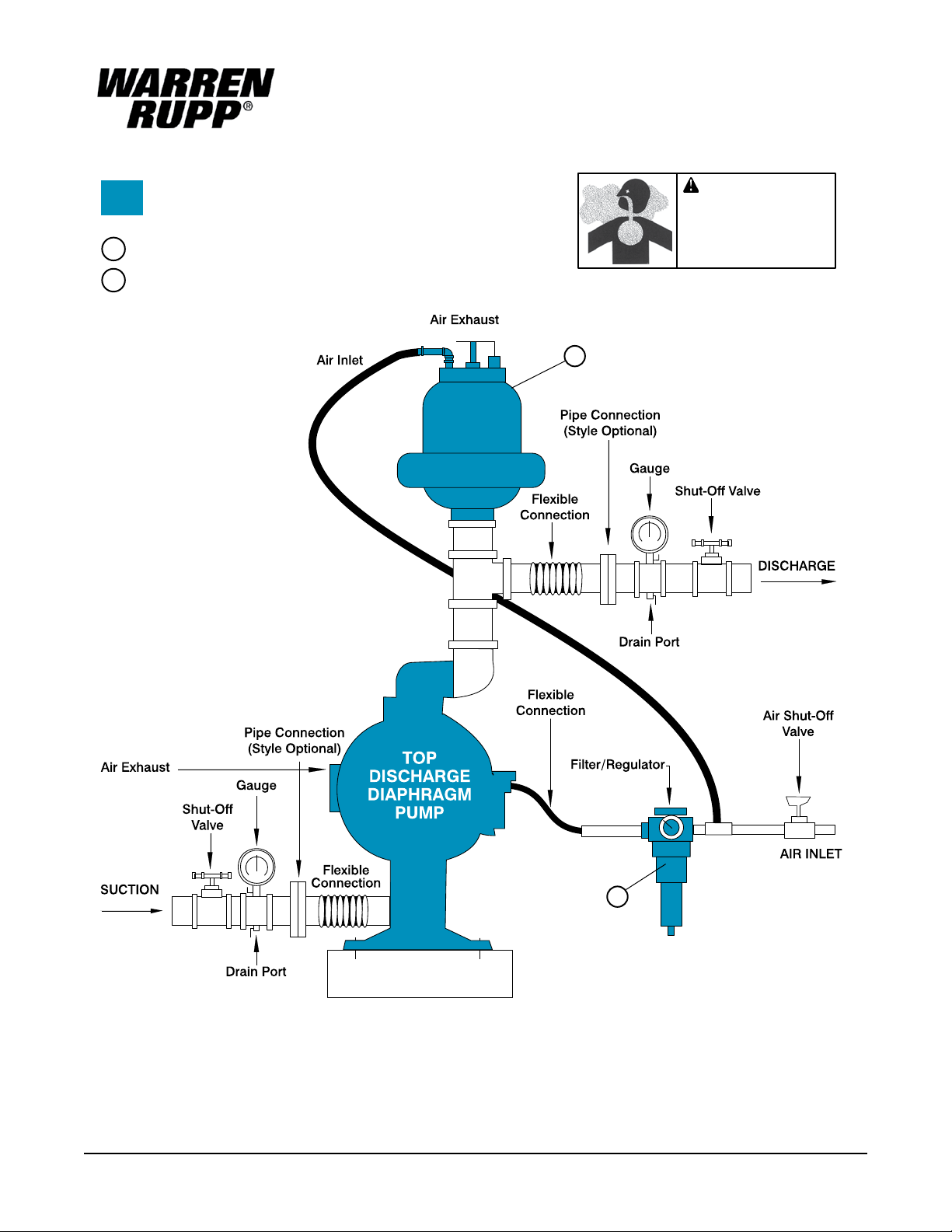
INSTALLATION GUIDE
Top Discharge Ball or Flap Valve Unit
Available from
Warren Rupp
1
Tranquilizer
Filter/Regulator�
2
®
/Surge Supressor
CAUTION
The air exhaust should be
piped to an area for safe
disposition of the product
being pumped, in the event
of a diaphragm failure.
1
Surge
Suppressor
2
st15dl4sm-rev0614 Models ST1½, ST40 Page 5
Page 8

For installations involving the use of rigid piping, short exible sections of hose are
recommended between the pump and piping. This will reduce piping strains and
vibration.
FILLING THE DRIVER CHAMBERS WITH LIQUID
THE DRIVER CHAMBERS WILL BE FILLED WITH DISTILLED WATER AT THE
FACTORY. IF THE INNER CHAMBER IS CAST IRON, THE UNIT IS FILLED WITH
ETHYLENE GLYCOL.
If you prefer to substitute another liquid, to prevent system contamination consult the
factory rst to determine compatibility of the substitute with pump construction.
Follow the steps listed below to replace the liquid in the pump after disassembly or
liquid loss:
1. Disconnect air supply from pump before starting any work. Remove the ll and drain
plugs (¼ NPT) (.0635 cm) from the driver chambers. After the chambers are completely
drained of all liquid, replace the drain plugs and tighten them securely. NOTE: Use thread
sealant on plug threads.
2. Remove the two large (1 NPT) (2.54 cm) pipe plugs (one on each side) located in
the rear of the innermost air chambers.
3. Determine which side of the pump is on the discharge stroke and which side is on
the suction stroke by checking the positions of the diaphragm assemblies. The cast inner
diaphragm plate closest to the pump intermediate housing, or centerline, is the chamber
in the suction stroke position. The opposite chamber, with cast inner diaphragm plate
away from unit centerline, is in the discharge stroke position. NOTE: The diaphragm
assemblies (cast inner diaphragm plates) are visible through the two tapped holes in
the inner chambers from which the two large pipe plugs were removed.
4. Fill the driver chamber on the suction side of the pump with 1.20 liters or 40 to 41
uid oz. by volume accuracy to 1 oz. (28.41 ml) with the driver liquid chosen for use.
The driver liquid chambers must be lled with the correct amount of the driver liquid as
too little or too much liquid can cause premature diaphragm failure and erratic pumping.
5. After lling, the liquid will not come all the way to the top of the lling hole. Use a
screwdriver or similar tool to apply leverage on the inner diaphragm plate (diaphragm
assembly) forcing the driver diaphragm on the side you have just lled partially through
its discharge stroke until the liquid level in the chamber you are lling comes to the top of
the ll hole. This displaces any air in the chamber. CAUTION: Do not pry on or damage
the elastomer diaphragm while performing this step of the lling instructions.
6. Re-plug the ll hole and tighten securely. NOTE: Use thread sealant on plug threads
and tighten only until snug.
7. Using a screwdriver or similar tool apply leverage on the inner diaphragm plate
(diaphragm assembly), on the side just lled, forcing the pump to “shift” or reverse
diaphragm positions.
8. Follow steps (4) thru (6) to ll the opposite driver chamber.
9. Re-install the two large pipe plugs in the rear of the pump inner air chambers.
NOTE: Use thread sealant on plug threads.
Revised Filling Procedure:
For pumps with air valve 031-098-000
Insert the safety clip (210-008-330, item 61) on one side of the main air valve body
and cycle the pump at 5 to 10 psi. As you face the pump, the side with the pin should
be the rst driver uid reservoir to be lled. The driver diaphragm will be on a suction
stroke. Pour the correct amount of liquid into the reservoir. The uid level will not come
completely to the top. Loosely install the pipe plug, with pipe dope, PTFE tape or o-ring
(depending on pump model) placed on the threads. Release all air pressure to the pump
and remove the safety clip. The diaphragm will relax and will come to center. Watch the
loose pipe plug closely as air escapes and the driver uid level rises. Insert the safety
clip on the opposite side and add a small amount of air pressure. When you see liquid
weeping out between the loose pipe plug and ll hole, tighten the pipe plug. Repeat the
procedure for the unlled chamber.
If you have a problem getting the driver uid to come to the top, a blunt instrument
can be inserted into the chamber port of the pump and pressure can manually be applied
to the pumping diaphragm to cause the liquid to come to the top. Do this carefully.
A needle valve for precision stroking control is recommended at the air inlet for this
procedure. Please be aware that air left in the chambers will result in faulty operation of
the pump and will cause premature pumping diaphragm failure.
st15dl4sm-rev0614 Models ST1½, ST40 Page 6
Page 9

ST1½-A volume for non-overlay = 1200ml / 40.6 . oz.
Use pipe dope on pipe plugs. Cast iron uid chambers typically lled with normal
antifreeze.
CHAMBER PORTING
This unit is equipped with ball check valves and is furnished with side chamber porting
as standard. This arrangement is suitable for most pumping applications. A conversion
kit of elbows is available for optional top or bottom porting when required. Top porting is
recommended for operation at extremely low ow rates and high discharge pressures,
to eliminate accumulated air or vapor from the pumping chamber.
AIR SUPPLY
DO NOT CONNECT unit to air supply in excess of 125 PSI (8.61 Bars). Install a shutoff
valve in the air supply line to permit removal of the unit for servicing. When connecting the
unit to an air supply of rigid piping, use a section of exible line to the pump to eliminate
piping strain.
OPERATION
This pump has been tested prior to shipment and is ready for use as received.
Make certain that the capacity at which the pump is operating is not limited by
the suction conditions involved (see installation procedures). Keep in mind that the
diaphragms will move at a rate proportional to inlet air ow. If the cycling rate is allowed
to exceed the rate that liquid can enter the chamber that is on the suction stroke the liquid
is simply pulled apart (cavitation) and the pump’s displacement is reduced. For the most
efcient use of compressed air and longest diaphragm service life, always throttle the air
inlet to the lowest cycling rate that does not decrease the ow rate.
Start the unit by opening the air inlet valve approximately ½ to ¾ turn. After the unit
starts pumping the air inlet valve can be opened to increase the pumping capacity as
desired. When further opening of the valve increases the cycling rate without an increase
in capacity, cavitation exists; and the valve should be closed slightly.
FREEZING OR ICING OF EXHAUST
Icing of air exhaust can occur under certain conditions of temperature and humidity
on all compressed air powered equipment. When performance loss due to icing is
experienced, use of an air dryer should eliminate this condition. Icing will be more
prevalent at high discharge pressures.
AIR EXHAUST
SANDPlPER pumps can be submerged if the materials of construction are compatible
with the liquid and the exhaust is piped above the liquid level. Piping used for the exhaust
should not be smaller than 1" (2.54 cm) pipe size. Reduced pipe size can restrict the
exhausted air and cause reduced pump performance.
When the product being pumped is at a level above the pump (ooded suction), the
exhaust should be piped to a higher level than the product in order to prevent spillage
caused by siphoning.
MAINTENANCE AFTER USE
When this pump is used to handle materials that settle out or transform from a liquid
to a solid form, care must be taken after each use and during idle periods to remove or
ush these materials from the pump as required. Failure to do this could result in possible
premature diaphragm failure.
To drain liquid from the pump, turn the unit over on the manifold side. This position
puts the chamber ports down and will allow the check balls to fall away from the seats
allowing complete draining of the unit. This procedure is important to ensure complete
draining in freezing weather. NOTE: See note concerning operation of unit in freezing
conditions in “Installation Procedures”.
On permanent installations the pump chambers can be drained by removing the drain
plug in each outer chamber.
MAINTENANCE NOTE
A preventative maintenance procedure should be established to check the PTFE
pumping diaphragms for wear. Even though this part was proven to be good for millions
of cycles, the service life will vary with each application depending on the abrasive nature
of the liquid being pumped.
OUT
Ball
Valve
Seat
Ball
Check
Valve
Fig. 1 Check Valve Servicing
Discharge
Flange
Gasket
Ball Valve Seat
Gasket
Suction/
Discharge
Manifold
Gasket
Suction
Flange
st15dl4sm-rev0614 Models ST1½, ST40 Page 7
Page 10

The choice of the PTFE unit indicates that the material being handled is not compatible
with the standard materials of construction (Neoprene and aluminum). If a pumping
diaphragm (PTFE) were to fail, the unit would continue pumping via the driver diaphragm.
The elastomeric driver diaphragm would then be exposed to the liquid and failure of this
diaphragm due to attack would be the end result. At this point additional damage can
occur to the air valving portion of the pump and other internal parts and castings.
CHECK VALVE SERVICING
For best priming and most efcient pumping performance, it is important to maintain
check valves and valve seats in good condition for proper sealing. Need for inspection
or service of ball valves is usually indicated by poor priming, unstable cycling, reduced
performance, or pump cycles but will not pump.
Inspection and service of check valves requires the removal of six bolts which provides
access to all four ball valves and both, suction and discharge, valve seats. New ball
check valves are 2¼" (5.715 cm) diameter and will require replacement when worn to
approximately 2" (5.08 cm) diameter.
DIAPHRAGM SERVICING
DRIVER DIAPHRAGMS
Drain the driver liquid from the driver chamber on the side to be serviced. This is
accomplished by removing the drain plug in the bottom of the driver chamber. Remove the
four (4) ange nuts that secure the manifold assembly to the pump chambers. Remove
the manifold assembly from the pump. Remove the eight (8) hex nuts that secure the
inner pumping diaphragm chamber assembly to the driver inner diaphragm chamber and
remove the assembly by pulling axially off the studs. This will permit a quick inspection of
the PTFE pumping diaphragm as well as the driver diaphragm. It is not required that the
pumping diaphragm chambers be separated to get to the driver diaphragms.
To remove the driver diaphragm, loosen the diaphragm assembly by turning it out of
the shaft using a
turned out by hand by use of the diaphragm. Removal of the opposite pumping chamber
assembly will allow removal of the second driver diaphragm assembly and the shaft as
a unit. The interior components consisting of the shaft seals and sleeve bearing are now
accessible for inspection or service as required.
To disassemble the driver diaphragm assemblies, clamp the inner diaphragm plate
around the outer diameter in a vise to hold it while you turn the center screw loose from
the back plate and the assembly will come apart.
To remove the shaft from a diaphragm assembly, hold the shaft in a clamping device
making sure to protect the shaft surface so as not to scratch or mar it in any way. Then
the diaphragm assembly will turn loose using an Allen wrench
center screw.
All procedures for reassembling the diaphragms are just in reverse of previous
instructions for disassembly. The diaphragms are to be installed with their natural bulge
outward or toward the outer diaphragm plate. Make sure that the inner diaphragm plate
is installed with the at face against the diaphragm.
After all the components are in position in a vise and hand tightened, tighten with a
wrench to approximately 45 Ft./Lbs. (61.01 Newton meters) torque reading. After each
driver diaphragm assembly has been made thread one assembly into the shaft. Install this
subassembly into the pump and secure it by placing the pumping chamber assembly over
it and secure it in place with the eight (8) hex nuts. This will hold the diaphragm assembly
in place while the opposite side is installed. Make sure the last diaphragm assembly is
torqued into the shaft at 30 Ft./Lbs. (40.67 Newton meters). This nal torquing will lock
the diaphragm assemblies together. Place the remaining pumping chamber assembly on
the open end and secure it by tightening the nuts gradually and evenly.
PUMPING DIAPHRAGMS
It is recommended that the above procedure be followed to the point of removing the
pumping chamber assembly from the unit. Remove the hex nuts and capscrews that
secure the assembly together and lift off the outer chamber from the assembly. This
exposes the PTFE pumping diaphragm and allows access to the o-ring seal behind it.
The re-assembly is just in reverse of the above as follows: Install the o-ring seal in the
groove provided on the inner chamber. Replace the PTFE diaphragm and place the outer
chamber on the assembly making sure that the chambers inlet-outlet port centerline is
perpendicular to the centerline formed by the ll and drain plugs in the inner chamber.
Replace all fasteners that secure the assembly together and torque them at 33 Ft./Lbs.
3
/8" (.9525 cm) Allen wrench. Once the assembly has turned, it can be
3
/8" (.9525 cm) on the
Diaphragm
Inner
Diaphragm
Chamber
Outer
Diaphragm
Plate
Driver
Diaphragm
Inner
Flat Head
Plate
Capscrew
“O” Ring
Inner
Diaphragm
Chamber
Fig. 2 Diaphragm Servicing
PTFE®
Pumping
Diaphragm
“O” Ring
Outer
Diaphragm
Chamber
st15dl4sm-rev0614 Models ST1½, ST40 Page 8
Page 11

(44.74 Newton meters) alternating from one side to the other in the process. Do not
overtighten these bolts due to the nature of PTFE to cold ow.
Reinstall the pumping chamber assembly on the pump as it was removed and ll with
the driver liquid as called out in this text. After complete re-assembly the unit should be
tested prior to installation on the job simply to make sure the capscrews and hex nuts
are torqued down properly to ensure no leakage around the PTFE diaphragm surfaces.
A NOTE ABOUT AIR VALVE LUBRICATION
The SANDPIPER pump’s pilot valve and main air valve assemblies are designed
to operate WITHOUT lubrication. This is the preferred mode of operation. There may
be instances of personal preference, or poor quality air supplies when lubrication of
the compressed air supply is required. The pump air system will operate with properly
lubricated compressed air supplies. Proper lubrication of the compressed air supply
would entail the use of an air line lubricator (available from Warren Rupp) set to deliver
one drop of 10 wt., non-detergent oil for every 20 SCFM of air the pump consumed at its
point of operation. Consult the pump’s published Performance Curve to determine this.
It is important to remember to inspect the sleeve and spool set routinely. It should
move back and forth freely. This is most important when the air supply is lubricated. If a
lubricator is used, oil accumulation will, over time, collect any debris from the compressed
air. This can prevent the pump from operating properly.
Water in the compressed air supply can create problems such as icing or freezing
of the exhaust air causing the pump to cycle erratically, or stop operating. This can be
addressed by using a point of use air dryer to supplement a plant’s air drying equipment.
This device will remove excess water from the compressed air supply and alleviate the
icing or freezing problem.
ESADS: EXTERNALLY SERVICEABLE AIR
DISTRIBUTION SYSTEM
Please refer to the exploded view drawing and parts list in the Service Manual supplied
with your pump. If you need replacement or additional copies, contact your local Warren
Rupp Distributor, or the Warren Rupp factory Literature Department at the number shown
below. To receive the correct manual, you must specify the MODEL and TYPE in formation
found on the name plate of the pump.
MODELS WITH 1" SUCTION/DISCHARGE OR LARGER, AND
METAL CENTER SECTIONS
The main air valve sleeve and spool set is located in the valve body mounted on the
pump with four hex head capscrews. The valve body assembly is removed from the
pump by removing these four hex head capscrews.
With the valve body assembly off the pump, access to the sleeve and spool set is
made by removing four hex head capscrews (each end) on the end caps of the valve
body assembly. With the end caps removed, slide the spool back and forth in the sleeve.
The spool is closely sized to the sleeve and must move freely to allow for proper pump
operation. An accumulation of oil, dirt or other contaminants from the pump’s air supply,
or from a failed diaphragm, may prevent the spool from moving freely. This can cause
the spool to stick in a position that prevents the pump from operating. If this is the case,
the sleeve and spool set should be removed from the valve body for cleaning and further
inspection.
Remove the spool from the sleeve. Using an arbor press or bench vise (with an
improvised mandrel), press the sleeve from the valve body. Take care not to damage the
sleeve. At this point, inspect the o-rings on the sleeve for nicks, tears or abrasions. Damage
of this sort could happen during assembly or servicing. A sheared or cut o-ring can allow
the pump’s compressed air supply to leak or bypass within the air valve assembly, causing
the pump to leak compressed air from the pump air exhaust or not cycle properly. This
is most noticeable at pump dead head or high discharge pressure conditions. Replace
any of these o-rings as required or set up a routine, preventive maintenance schedule
to do so on a regular basis. This practice should include cleaning the spool and sleeve
components with a safety solvent or equivalent, inspecting for signs of wear or damage,
and replacing worn components.
st15dl4sm-rev0614 Models ST1½, ST40 Page 9
Page 12

To re-install the sleeve and spool set, lightly lubricate the o-rings on the sleeve with
an o-ring assembly lubricant or lightweight oil (such as 10 wt. air line lubricant). Press
the set into the valve body easily, without shearing the o-rings. Re-install one end cap,
gasket and bumper on the valve body. Using the arbor press or bench vise that was used
in disassembly, press the sleeve back into the valve body. You may have to clean the
surfaces of the valve body where the end caps mount. Material may remain from the old
gasket. Old material not cleaned from this area may cause air leakage after reassembly.
Take care that the bumper stays in place allowing the sleeve to press in all the way.
Re-install the spool, the opposite end cap, gasket and bumper on the valve body.
After inspecting and cleaning the gasket surfaces on the valve body and intermediate,
re-install the valve body on the pump using new gaskets. Tighten the four hex head
capscrews evenly and in an alternating cross pattern.
PlLOT VALVE
This assembly is reached by removing the air distribution valve body from the pump
and lifting the pilot valve body out of the intermediate housing. Follow the instruction
above for the air distribution valve when servicing the pilot valve.
When reinserting an externally serviceable pilot valve, push both plungers out of the
path of the pilot valve so that they and the pilot valve are not damaged.
Service Note: If a problem arises with the pilot valve, it is usually corrected by
replacing only o-rings. Always grease the spool prior to inserting into the sleeve. If the
sleeve is removed from the body, reinsertion must be from the same side it was removed
from, the chambered side. Again, grease the o-rings so that it slides into the body. Make
sure the retaining ring has securely been inserted around the sleeve.
Service Note: When re-installing pilot valve (Item 6), make sure that plunger pins
(Item 5) are both pushed as far as possible in, toward the diaphragms. Large head as
close to casting as possible; otherwise, these items may be damaged.
PILOT VALVE ACTUATOR
The bushings for the pilot valve actuators are threaded into the intermediate bracket
from the outside. The plunger may be removed for inspection or replacement from the
inside by removing the air distribution valve body and the pilot valve body from the pump.
The plungers should be visible through the intermediate from the top. Depending on their
position, you may nd it necessary to use a ne piece of wire to pull them out. Under
rare circumstances, it may be necessary to replace the o-ring seal.
To replace the o-ring, the bushing can be turned out through the inner chamber by
removing the outer chamber assembly to reach the bushing.
IMPORTANT
This pump is pressurized internally with air pressure during operation—always make
certain all bolting is in good condition and that all of correct bolting is reinstalled during
assembly.
WARRANTY
This unit is guaranteed for a period of ve years against defective material and
workmanship.
st15dl4sm-rev0614 Models ST1½, ST40 Page 10
Page 13

IMPORTANT SAFETY
INFORMATION
IMPORTANT
Read these safety warnings
Read these safety warnings
and instructions in this
and instructions in this
manual completely, before
manual completely, before
installation and start-up
of the pump. It is the responsibility of the
of the pump. It is the responsibility of the
purchaser to retain this manual for reference.
purchaser to retain this manual for reference.
Failure to comply with the recommendations
Failure to comply with the recommendations
stated in this manual will damage the pump,
stated in this manual will damage the pump,
and void factory warranty.
and void factory warranty.
prevent leakage. Follow recommended torques
gas will void the warranty.
line may be pressurized and must be bled of
its pressure.
pumping a product which is hazardous or toxic,
the air exhaust must be piped to an appropriate
area for safe disposition.
installation and start-up
CAUTION
Before pump operation,
inspect all gasketed
fasteners for looseness
caused by gasket creep. Re-
torque loose fasteners to
stated in this manual.
CAUTION
Pump not designed,
tested or certied to be
powered by compressed
natural gas. Powering
the pump with natural
WARNING
Before maintenance
or repair, shut off the
compressed air line,
bleed the pressure, and
disconnect the air line from
the pump. The discharge
WARNING
In the event of diaphragm
rupture, pumped material
may enter the air end of the
pump, and be discharged
into the atmosphere. If
WARNING
Take action to prevent static
sparking. Fire or explosion
can result, especially when
handling ammable liquids.
containers or other miscellaneous equipment
must be grounded. (See page 12)
The pump, piping, valves,
WARNING
This pump is pressurized
internally with air pressure
during operation. Always
make certain that all bolting
is in good condition and
bolting is reinstalled during assembly.
that all of the correct
WARNING
When used for toxic or
aggressive uids, the pump
should always be ushed
clean prior to disassembly.
WARNING
Before doing any
maintenance on the pump,
be certain all pressure is
completely vented from the
pump, suction, discharge,
openings and connections. Be certain the air
supply is locked out or made non-operational,
so that it cannot be started while work is being
done on the pump. Be certain that approved
eye protection and protective clothing are worn
all times in the vicinity of the pump. Failure to
follow these recommendations may result in
serious injury or death.
piping, and all other
WARNING
Airborne particles and
loud noise hazards.
Wear ear and eye
protection.
WARNING
Use safe practices
when lifting
kg
RECYCLING
Many components of SANDPIPER® AODD pumps are made of
recyclable materials (see chart on page 13 for material specications). We encourage pump users to recycle worn out parts and
pumps whenever possible, after any hazardous pumped uids are
thoroughly ushed.
st15dl4sm-rev0614 Models ST1½, ST40 Page 11
Page 14

Grounding The Pump
This end is installed to a true earth ground.
This end is fastened to the pump hardware.
WARNING
Take action to prevent static sparking.
Fire or explosion can result, especially
when handling ammable liquids. The
pump, piping, valves, containers or
other miscellaneous equipment must
be grounded.
This 8 foot long (244
centimeters) Ground Strap, part
number 920-025-000 can be
ordered as a service item.
To reduce the risk of static electrical sparking, this pump must be
grounded. Check the local electrical code for detailed grounding
instruction and the type of equipment required, or in the absence of local
codes, an industry or nationally recognized code having juristiction over
specic installations.
st15dl4sm-rev0614 Models ST1½, ST40 Page 12
Page 15

MATERIAL CODES
THE LAST 3 DIGITS OF PART NUMBER
000 Assembly, sub-assembly;
and some purchased items
010 Cast Iron
012 Powered Metal
015 Ductile Iron
020 Ferritic Malleable Iron
025 Music Wire
080 Carbon Steel, AISI B-1112
100 Alloy 20
110 Alloy Type 316 Stainless Steel
111 Alloy Type 316 Stainless Steel
(Electro Polished)
112 Alloy C
113 Alloy Type 316 Stainless Steel
(Hand Polished)
114 303 Stainless Steel
115 302/304 Stainless Steel
117 440-C Stainless Steel (Martensitic)
120 416 Stainless Steel
(Wrought Martensitic)
123 410 Stainless Steel
(Wrought Martensitic)
148 Hardcoat Anodized Aluminum
149 2024-T4 Aluminum
150 6061-T6 Aluminum
151 6063-T6 Aluminum
152 2024-T4 Aluminum (2023-T351)
154 Almag 35 Aluminum
155 356-T6 Aluminum
156 356-T6 Aluminum
157 Die Cast Aluminum Alloy #380
158 Aluminum Alloy SR-319
159 Anodized Aluminum
162 Brass, Yellow, Screw Machine Stock
165 Cast Bronze, 85-5-5-5
166 Bronze, SAE 660
170 Bronze, Bearing Type, Oil Impregnated
175 Die Cast Zinc
180 Copper Alloy
305 Carbon Steel, Black Epoxy Coated
306 Carbon Steel, Black PTFE Coated
307 Aluminum, Black Epoxy Coated
308 Stainless Steel, Black PTFE Coated
309 Aluminum, Black PTFE Coated
310 PVDF Coated
313 Aluminum, White Epoxy Coated
330 Zinc Plated Steel
331 Chrome Plated Steel
332 Aluminum, Electroless Nickel Plated
333 Carbon Steel, Electroless
Nickel Plated
335 Galvanized Steel
336 Zinc Plated Yellow Brass
337 Silver Plated Steel
340 Nickel Plated
342 Filled Nylon
351 Food Grade Santoprene; Color: NATURAL
353 Geolast; Color: BLACK
354 Injection Molded #203-40
Santoprene- Duro 40D +/-5; Color: RED
355 Thermal Plastic
356 Hytrel; Color: BLUE
357 Injection Molded Polyurethane;
Color: GREEN
358 Urethane Rubber; Color: NATURAL
(Some Applications)
(Compression Mold)
359 Urethane Rubber; Color: NATURAL
360 Nitrile Rubber; Color Coded: RED
361 Nitrile
363 FKM (Fluorocarbon).
Color Coded: YELLOW
364 E.P.D.M. Rubber. Color Coded: BLUE
365 Neoprene Rubber;
Color Coded: GREEN
366 Food Grade Nitrile; Color: WHITE
368 Food Grade EPDM; Color: GRAY
370 Butyl Rubber
Color Coded: BROWN
371 Philthane (Tuftane)
374 Carboxylated Nitrile
375 Fluorinated Nitrile
378 High Density Polypropylene
379 Conductive Nitrile;
Color Coded: RED & SILVER
384 Conductive Neoprene;
Color Coded: GREEN & SILVER
405 Cellulose Fibre
408 Cork and Neoprene
425 Compressed Fibre
426 Blue Gard
440 Vegetable Fibre
465 Fibre
500 Delrin 500
501 Delrin 570
502 Conductive Acetal, ESD-800;
Color: BLACK
503 Conductive Acetal, Glass-Filled
Color: BLACK; Color Coded: YELLOW
505 Acrylic Resin Plastic
506 Delrin 150
520 Injection Molded PVDF; Color: NATURAL
521 Injection Molded Conductive PVDF;
Color: BLACK; Color Coded: LIGHT
GREEN
540 Nylon
541 Nylon
542 Nylon
544 Nylon Injection Molded
550 Polyethylene
551 Glass Filled Polypropylene; Color: BLACK
552 Unlled Polypropylene; Color: NATURAL
555 Polyvinyl Chloride
556 Black Vinyl
557 Conductive Polypropylene;
Color: BLACK; Color Coded: SILVER
558 Conductive HDPE; Color: BLACK
Color Coded: SILVER
559 Conductive Polypropylene; Color: BLACK
Color Coded: SILVER
570 Rulon II
580 Ryton
590 Valox
591 Nylatron G-S
592 Nylatron NSB
600 PTFE (virgin material)
Tetrauorocarbon (TFE)
601 PTFE (Bronze and moly lled)
602 Filled PTFE
603 Blue Gylon
604 PTFE
606 PTFE
607 Envelon
608 Conductive PTFE; Color: BLACK
610 PTFE Encapsulated Silicon
611 PTFE Encapsulated FKM
632 Neoprene/Hytrel
633 FKM/PTFE
634 EPDM/PTFE
635 Neoprene/PTFE
637 PTFE , FKM/PTFE
638 PTFE , Hytrel/PTFE
639 Nitrile/TFE
643 Santoprene®/EPDM
644 Santoprene®/PTFE
656 Santoprene Diaphragm and
Check Balls/EPDM Seats
661 EPDM/Santoprene
666 FDA Nitrile Diaphragm,
PTFE Overlay, Balls, and Seals
668 PTFE, FDA Santoprene/PTFE
Delrin is a registered
tradename of E.I. DuPont.
Gylon is a registered tradename
of Garlock, Inc.
Nylatron is a registered tradename
of Polymer Corp.
Santoprene is a registered tradename
of Exxon Mobil Corp.
Rulon II is a registered tradename
of Dixion Industries Corp.
Ryton is a registered tradename
of Phillips Chemical Co.
Valox is a registered tradename
of General Electric Co.
PortaPump, Tranquilizer and SludgeMaster are
registered tradenames of Warren Rupp, Inc.
st15dl4sm-rev0614 Models ST1½, ST40 Page 13
Page 16

SERVICE & OPERATING MANUAL
II 2GD T5
Original Instructions
Model ST1½ Type 4
See pages 18 & 19
for ATEX ratings
Model ST40 Type 4
ITEM TOTAL
NO. PART NUMBER DESCRIPTION RQD.
1 070-006-170 Bearing, Sleeve 2
2 114-002-156 Bracket, Intermediate 1
114-002-010 Bracket, Intermediate 1
3 720-004-360 Seal, U-Cup 2
4 135-008-000 Bushing, Threaded (with O-Ring) 2
5 620-004-114 Plunger, Actuator 2
6 095-073-000 Pilot Valve Body Ass’y.
6-A 095-070-551 Pilot Valve Body 1
6-B 755-025-000 Sleeve (with O-Ring) 1
6-C 560-033-360 O-Ring (Sleeve) 4
6-D 775-026-000 Spool (with O-Ring) 1
6-E 560-023-360 O-Ring (Spool) 2
6-F 675-037-080 Retaining Ring 1
7 360-041-379 Gasket, Valve Body 1
8 560-001-360 O-Ring (Sold with Item 4) 2
9 530-036-000 Mufer, Exhaust 1
10 095-043-156 Body, Valve 1
095-043-010 Body, Valve 1
11 132-014-358 Bumper, Valve Spool 2
12 165-066-010 End Cap Assembly 2
13 360-048-425 Gasket, Valve Body 1
14 360-010-425 Gasket, End Cap 2
15 560-020-360 O-Ring 6
16 031-066-000 Sleeve & Spool Set 1
17 170-032-115 Capscrew, Hex Hd., 1/4-20 Size 8
18 170-045-115 Capscrew, Hex Hd., 5/16-18 Size 4
19 132-002-360 Bumper, Diaphragm Plate 2
20 560-022-360 O-Ring 2
21 685-007-120 Rod, Diaphragm 1
22 196-029-156 Chamber, Inner Diaphragm 2
196-029-015 Chamber, Inner Diaphragm 2
23-1 115-062-080 Bracket, Foot, Left Hand 2
23-2 115-062-080 Bracket, Foot, Right Hand 2
24 612-052-157 Plate, Inner Diaphragm 2
612-052-010 Plate, Inner Diaphragm 2
25 612-096-110 Plate, Outer Diaphragm 2
26 170-024-115 Capscrew, Hex Hd., 7/16-14 Size 8
27 900-006-115 Washer, Lock 7/16 Size 48
28 618-007-115 Plug, Pipe 1 NPT Size 2
29 286-005-365 Diaphragm 2
286-005-364 Diaphragm 2
286-005-363 Diaphragm 2
30 902-003-000 Stat-O Seal 2
31 196-028-156 Chamber, Driver 2
196-028-010 Chamber, Driver 2
32 807-033-115 Stud 7/16-14 Size 16
34 545-007-115 Nut, Hex 7/16-14 Size 40
35 170-058-115 Capscrew, Hex Hd. 7/16-14 Size 4
36 170-060-115 Capscrew, Hex Hd. 7/16-14 Size 20
37 618-003-110 Plug, Pipe 1/4 NPT Size 4
38 560-043-360 O-Ring 2
560-043-363 O-Ring 2
560-043-364 O-Ring 2
39 807-017-115 Stud 7/16-14 Size 4
40 170-006-330 Capscrew, Hex Hd., 3/8-16 Size 4
1
Available only in kit form. Order Kit 031-055-000 which also includes items 5 ,7, 13 and 60.
1
1
Repair Parts shown in bold face
(darker) type are more likely to need
replacement after extended periods
of normal use. They are readily
available from most Warren Rupp
distributors. The pump owner may
prefer to maintain a limited inventory of these parts in his own stock
to reduce repair downtime to a
minimum.
IMPORTANT: When ordering repair parts
always furnish pump model number,
serial number and type number.
st15dl4sm-rev0614 Models ST1½, ST40 Page 14
Page 17

ITEM TOTAL
NO. PART NUMBER DESCRIPTION RQD.
42 545-005-330 Nut, Hex 3/8-16 Size 4
43 905-001-330 Washer Taper 4
44 545-007-115 Nut, Hex 7/16-14 Size 4
47 900-005-330 Washer, Lock 3/8 Size 4
48 612-007-150 Plate, Base 1
612-007-080 Plate, Base 1
50 360-022-600 Gasket, Manifold/Chamber 2
51 196-027-110 Chamber, Outer Diaphragm 2
196-027-112 Chamber, Outer Diaphragm 2
196-027-156 Chamber, Outer Diaphragm 2
196-027-010 Chamber, Outer Diaphragm 2
52 286-017-604 Diaphragm 2
53 618-003-112 Plug, Pipe 1/4 NPT Size 4
618-003-110 Plug, Pipe 1/4 NPT Size 4
54-1 050-010-600 Ball, Check Valve 4
54-2 170-035-115 Capscrew (SS and Alloy C) 7/16-14 size 4
170-023-115 Capscrew (Aluminum, CI, HC) 7/16-14 size 4
54-3 170-040-115 Capscrew, Hex Hd., 3/8-16 size 6
54-4 334-006-110 Flange, Discharge 1
334-006-112 Flange, Discharge 1
334-006-156 Flange, Discharge 1
334-006-010 Flange, Discharge 1
54-5 334-007-110 Flange, Suction 1
334-007-112 Flange, Suction 1
334-007-156 Flange, Suction 1
334-007-010 Flange, Suction 1
54-6 334-008-110 Flange, Threaded (NPT) 2
334-008-112 Flange, Threaded (NPT) 2
334-008-156 Flange, Threaded (NPT) 2
334-008-010 Flange, Threaded (NPT) 2
334-008-110E Flange, Threaded (BSP) 2
334-008-112E Flange, Threaded (BSP) 2
334-008-156E Flange, Threaded (BSP) 2
334-008-010E Flange, Threaded (BSP) 2
54-7 360-017-608 Gasket, Manifold to seat 4
54-8 518-003-110 Manifold, Suction-Discharge 1
518-003-112 Manifold, Suction-Discharge 1
518-003-156 Manifold, Suction-Discharge 1
518-003-010 Manifold, Suction-Discharge 1
54-9 545-005-115 Nut, Hex 3/8-16 Size 6
54-10 560-028-610 O-Ring 2
54-11 722-010-110 Check Ball Valve Seat w/Retainer (Suction) 1
722-010-112 Check Ball Valve Seat w/Retainer (Suction) 1
54-12 900-005-115 Washer, Lock 3/8 Size 6
54-14 722-031-110 Check Ball Valve Seat w/Retainer (Discharge) 1
722-031-112 Check Ball Valve Seat w/Retainer (Discharge) 1
57 560-070-610 O-Ring 2
58 171-002-110 Capscrew, Flat Hd. Socket 2
59 618-003-110 Plug, Pipe 2
60 132-022-360 Bumper 2
61 210-008-330 Clip, Safety 1
62 560-023-360 O-Ring, Endcap 2
63 920-025-000 Ground Strap 1
Repair Parts shown in bold face
(darker) type are more likely to need
replacement after extended periods of
normal use. They are readily available
from most Warren Rupp distributors. The pump owner may prefer to
maintain a limited inventory of these
parts in his own stock to reduce repair
downtime to a minimum.
IMPORTANT: When ordering repair parts
always furnish pump model number, serial
number and type number.
Not Shown:
242-001-000 Fill Bottle 1
031-098-156 Main Air Valve Assy. 1
031-098-311 (Inc. Items 10, 11, 12, 14, 15, 16,17) 1
st15dl4sm-rev0614 Models ST1½, ST40 Page 15
Page 18

A= These items available in kit
form only. Order angle valve
kit P/N 475-102-000.
B= These items available in kit
fprm only. Order rubber foot kit
P/N 475-101-000.
©2010 Warren Rupp, Inc. All rights reserved.
st15dl4sm-rev0614 Models ST1½, ST40 Page 16
Page 19

Declaration of Conformity
Manufacturer:
®
Warren Rupp, Inc.
Mansfield, Ohio, 44902 USA
certifies that Air-Operated Double Diaphragm Pump Series: HDB, HDF,
M Non-Metallic, S Non-Metallic, M Metallic, S Metallic, T Series, G Series, RS Series
U Series, EH and SH High Pressure, W Series, SMA and SPA Submersibles,
and Tranquilizer Surge Suppressors comply with the European Community
Directive 2006/42/EC on Machinery, according to Annex VIII. This product
has used Harmonized Standard EN809:1998+A1:2009, Pumps and Pump Units
for Liquids - Common Safety Requirements, to verify conformance.
Signature of authorized person
, 800 N. Main Street
October 20, 2005
Date of issue
David Roseberry
Printed name of authorized person
Revision Level: F
Engineering Manager
Title
April 19, 2012
Date of revision
Page 20

EC Declaration of Conformity
In accordance with ATEX Directive 94/9/EC,
Equipment intended for use in potentially explosive environments.
Manufacturer:
Warren Rupp, Inc.
A Unit of IDEX Corportion
800 North Main Street
P.O. Box 1568
Mansfield, OH 44902 USA
EN 60079-25: 2011
For pumps equipped with Pulse Output ATEX Option
Quality B.V. (0344)
AODD Pumps and Surge Suppressors
For Type Examination Designations, see page 2 (back)
AODD (Air-Operated Double Diaphragm) Pumps
EC Type Examination Certificate No. Pumps: KEMA 09ATEX0071 X
DEKRA Certification B.V. (0344)
Meander 1051
6825 MJ Arnhem
The Netherlands
®
Applicable Standard:
EN13463-1: 2009
EN13463-5: 2011
DATE/APPROVAL/TITLE:
14 MAY 2014
David Roseberry, Engineering Manager
Page 21

EC Declaration of Conformity
ATEX Summary of Markings
Type Marking Listed In
Pump types, S1F, S15, S20,
and S30 provided with the
pulse output option
Pump types, S1F, S15, S20,
and S30 provided with the
integral solenoid option
Pump types, HDB1½, HDB40,
HDB2, HDB50, HDB3, HDF1,
HDF25, HDF2, HDF3M, PB¼,
S05, S1F, S15, S20, S30, SB1,
SB25, ST1½, ST40, G15, G20,
and G30, without the above
listed options, no aluminum
parts
Pump types, DMF2, DMF3,
HDB1½, HDB40, HDB2,
HDB50, HDB3, HDF1, HDF25,
HDF2, HDF3M, PB¼, S05, S1F,
S15, S20, S30, SB1, SB25,
SE½, ST1, ST25, ST1½, ST40,
U1F, G05, G1F, G15, G20, and
G30
Surge Suppressors all types II 2 G T5
EC Type Certificate No. Pumps: KEMA 09ATEX0071 X
Type Certificate No. Pumps: KEMA 09ATEX0072 X
Type Certificate No. Suppressors: KEMA 09ATEX0073
II 2 G Ex ia c IIC T5
II 3/2 G Ex ia c IIC T5
II 2 D
Ex c iaD 20 IP67 T100oC
II 2 G EEx m c II T5
II 3/2 G EEx m c II T5
II 2 D c IP65 T100
II 1 G c T5
II 3/1 G c T5
II 1 D c T100
I M1 c
I M2 c
II 2 G c T5
II 3/2 G c T5
II 2 D c T100
II 3/2 G T5
II 2 D T100
Non-Conductive
Fluids
KEMA 09ATEX0071 X
CE 0344
KEMA 09ATEX0071 X
o
C
o
C
o
C
o
C
CE 0344
KEMA 09ATEX0071 X
KEMA 09ATEX0072 X
CE 0344
KEMA 09ATEX0072 X
CE
KEMA 09ATEX0073
CE
KEMA 09ATEX0071 X
KEMA 09ATEX0071 X
KEMA 09ATEX0071 X
KEMA 09ATEX0071 X
KEMA 09ATEX0071 X
KEMA 09ATEX0071 X
KEMA 09ATEX0071 X
KEMA 09ATEX0071 X
KEMA 09ATEX0071 X
KEMA 09ATEX0071 X
KEMA 09ATEX0072 X
KEMA 09ATEX0072 X
KEMA 09ATEX0072 X
KEMA 09ATEX0072 X
KEMA 09ATEX0073
KEMA 09ATEX0073
KEMA 09ATEX0073
No
Yes
Yes
No
Yes
Yes
No
Yes
Yes
No
Yes
No
Yes
Yes
No
Yes
Yes
Pumps marked with equipment Category II 3/1 G (internal 3 G /
eternal 1 G), 1D, M1 and M2 when used for non-conductive fluids.
The pumps are Category II 2 G when used for conductive fluids.
Pumps and surge suppressors marked with equipment Category II 3/2
(internal 3 G / external 2 G), 2D when used for non-conductive fluids.
The pumps are Category II 2 G when used for conductive fluids.
 Loading...