

Page 1

SERVICE & OPERATING MANUAL
See page 2
for ATEX ratings.
Original Instructions
Model M15 Metallic Design Level 1
Table of Contents
Engineering Data and Temperature Limitations .................................................... 1
Explanation of Pump Nomenclature ...................................................................... 2
Performance Curve ............................................................................................... 3
Dimensions ........................................................................................................... 4
Metric Dimensions ................................................................................................. 5
Principle of Pump Operation.................................................................................. 6
Installation and Start-Up ........................................................................................ 6
Air Supply .............................................................................................................. 6
Air Valve Lubrication ..............................................................................................6
Air Line Moisture.................................................................................................... 6
Air Inlet and Priming .............................................................................................. 6
Between Uses ....................................................................................................... 6
Installation Guide ................................................................................................... 7
Troubleshooting ..................................................................................................... 8
Warranty ................................................................................................................ 8
Recycling ............................................................................................................... 9
Important Safety Information ................................................................................. 9
Material Codes .................................................................................................... 10
Composite Repair Parts Drawing ........................................................................ 12
Available Service and Conversion Kits ................................................................ 12
Composite Repair Parts List ................................................................................ 13
Air Valve Drawing, Parts List, Service Instructions .............................................. 14
Air Valve Drawing, Parts List, Service Instructions ............................................. 15
Air Valve Drawing, Parts List, Service Instructions ............................................. 16
See pages 2, 30 and 31
for ATEX ratings.
Air Valve w/Stroke Indicator Drawing and Parts List ...........................................17
Air Valve w/Stroke Indicator Servicing ................................................................. 18
Solenoid Shifted Air Valve Drawing ..................................................................... 19
Solenoid Shifted Air Valve Parts List ................................................................... 19
Solenoid Shifted Air Valve Option ........................................................................ 20
Diaphragm Service Drawing, with Overlay .......................................................... 21
Diaphragm Service Drawing, Non-Overlay.......................................................... 21
Diaphragm Servicing ........................................................................................... 22
Overlay Diaphragm Servicing ............................................................................. 22
Pilot Valve Servicing, Assembly Drawing & Parts List ......................................... 23
Actuator Plunger Servicing .................................................................................. 24
Check Valve Servicing .........................................................................................25
Check Valve Drawing ..........................................................................................25
Optional Mufer Congurations ........................................................................... 26
Optional Mufer Conguration Drawing............................................................... 26
Pumping Hazardous Liquids................................................................................ 27
Converting Pump for Piping Exhaust Air .............................................................27
Converted Exhaust Illustration............................................................................. 27
Pulse Output Kit Drawing .................................................................................... 28
Pulse Output Kit Options ..................................................................................... 28
Grounding the Pump ........................................................................................... 29
CE Declaration of Conformity Machinery ............................................................ 30
CE Declaration of Conformity ATEX .................................................................... 31
Explanation of ATEX Certications ...................................................................... 32
m15mdl1sm-rev0713
Warren Rupp, Inc. • A Unit of IDEX Corporation • 800 N. Main St., Manseld, Ohio 44902 USA
Telephone (419) 524-8388 • Fax (419) 522-7867 • www.warrenrupp.com
©Copyright 2013 Warren Rupp, Inc. All rights reserved.
Page 2

Page 3
See page 2
for ATEX ratings.
See pages 2, 30 and 31
for ATEX ratings.
Quality System
ISO9001 Certied
Environmental
Management System
ISO14001 Certied
Air Inlet Side View
INTAKE/DISCHARGE PIPE SIZE
1½" NPT (internal)
1½" BSP Tapered (internal)
CAPACITY
0 to 106 gallons per minute
(0 to 401 liters per minute)
CAUTION! Operating temperature limitations are as follows:
Air Exhaust Side View
AIR VALVE
No-lube, no-stall
design
SOLIDS-HANDLING
Up to .25 in. (6mm)
M15 Metallic
Design Level 1
Ball Valve
Air-Operated
Double Diaphragm Pump
ENGINEERING, PERFORMANCE
& CONSTRUCTION DATA
HEADS UP TO
125 psi or 289 ft. of water
(8.6 Kg/cm2 or 86 meters)
Operating Temperatures
DISPLACEMENT/STROKE
.41 Gallon / 1.55 liter
Materials Maximum Minimum
Nitrile: General purpose, oil-resistant. Shows good solvent, oil, water and hydraulic uid resistance. Should not be used with highly polar solvents like
acetone and MEK, ozone, chlorinated hydrocarbons and nitro hydrocarbons.
EPDM: Shows very good water and chemical resistance. Has poor resistance to oil and solvents, but is fair in ketones and alcohols.
Neoprene: All purpose. Resistant to vegetable oil. Generally not affected by moderate chemicals, fats, greases and many oils and solvents. Generally
attacked by strong oxidizing acids, ketones, esters, nitro hydrocarbons and chlorinated aromatic hydrocarbons.
Santoprene®:: Injection molded thermoplastic elastomer with no fabric layer. Long mechanical ex life.
Excellent abrasion resistance.
Virgin PTFE: Chemically inert, virtually impervious. Very few chemicals are known to react chemically with PTFE- molten alkali metals, turbulent liquid or
gaseous uorine and a few uoro-chemicals such as chlorine triuoride or oxygen diuoride which readily liberate free uorine at elevated temperatures.
FKM (Fluorocarbon): Shows good resistance to a wide range of oils and solvents; especially all aliphatic, aromatic and halogenated hydrocarbons, acids,
animal and vegetable oils. Hot water or hot aqueous solutions (over 70°F) will attack FKM.
Polypropylene:
UHMW Polyethylene:
For specic applications, always consult the Warren Rupp Chemical Resistance Chart
SANDPIPER® pumps are designed to be powered only by compressed air.
190° F
88° C
280° F
138° C
200° F
93° C
275° F
135° C
220° F
104° C
350° F
177° C
180° F
82° C
180° F
82° C
Maximum and Minimum Temperatures are the limits for which these
materials can be operated. Temperatures coupled with pressure affect the
longevity of diaphragm pump components. Maximum life should not be
expected at the extreme limits of the temperature ranges.
-10° F
-23° C
-40° F
-40° C
-10° F
-23° C
-40° F
-40° C
-35° F
-37° C
-40° F
-40° C
-35° F
-37° C
32° F
0° C
m15mdl1sm-rev0713 Model M15 Metallic Page 1
Page 4
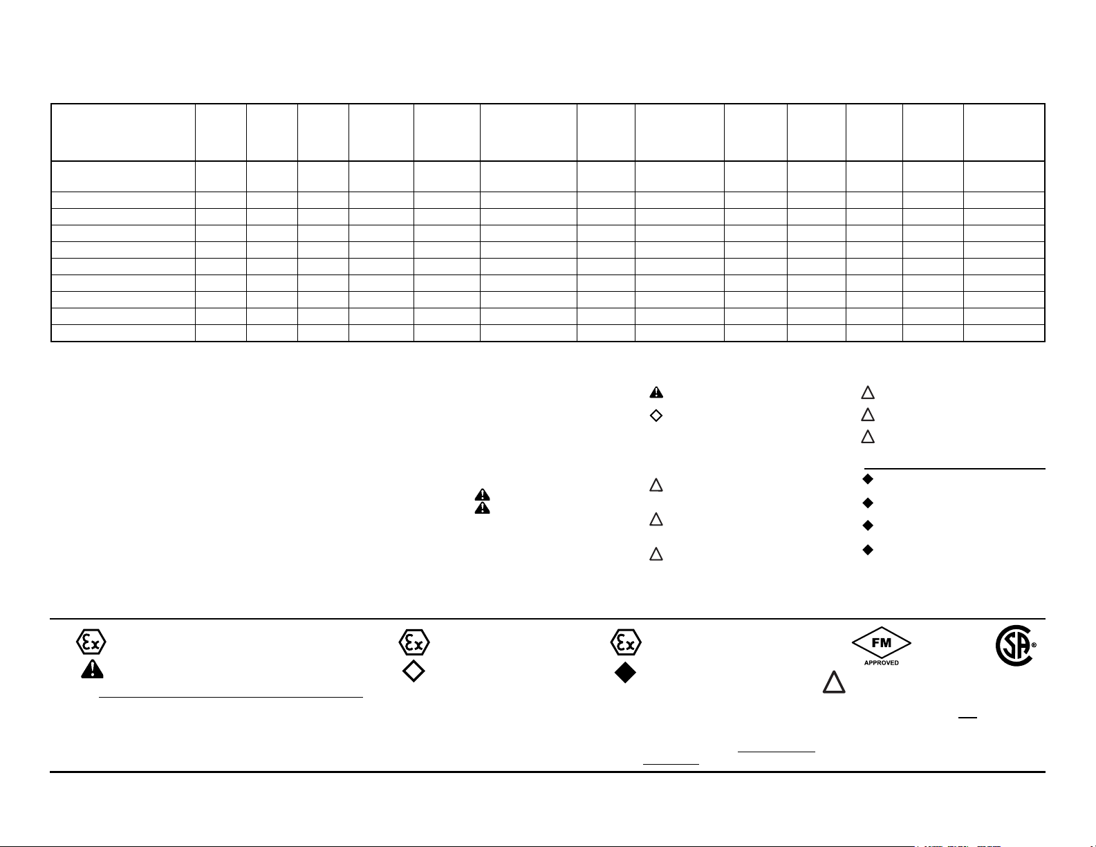
Explanation of Pump Nomenclature, M15 Metallic · Design Level 1· Ball Valve
II 2GD T5
II 2G Ex ia c IIC T5
II 2D c iaD 20 IP67 T100˚C
II 2G EEx m c T5
II 2D c IP65 T100°C
Check Diaphragm/ Check Non-Wetted Shipping
Model Pump Pump Valve Design Wetted Check Valve Valve Material Porting Pump Pump Kit Weight
Brand Size Type Level Material Materials Seat Options Options Style Options Options lbs. (kg)
M15B1ABWANS000. M 15 B 1 A B W A N S 0 00. 53 (24)
M15B1AEWANS000. M 15 B 1 A E W A N S 0 00. 53 (24)
M15B1ANWANS000. M 15 B 1 A N W A N S 0 00. 53 (24)
M15B1IBWANS000. M 15 B 1 I B W A N S 0 00. 93 (42)
M15B1IEWANS000. M 15 B 1 I E W A N S 0 00. 93 (42)
M15B1I1WANS000. M 15 B 1 I 1 W A N S 0 00. 93 (42)
M15B1IVTANS000. M 15 B 1 I V T A N S 0 00. 93 (42)
M15B1SGTANS000. M 15 B 1 S G T A N S 0 00. 95 (43)
M15B1S1WANS000. M 15 B 1 S 1 W A N S 0 00. 95 (43)
M15B1SVTANS000. M 15 B 1 S V T A N S 0 00. 95 (43)
Note: Models listed in the table are for reference only. See nomenclature below for other models.
Pump Brand
M= MARATHON
Pump Size
15=1½"
Check Valve Type
B= Ball
W= Weighted Ball
Design Level
1= Design Level
Wetted Material
A= Aluminum
I = Cast Iron
S= Stainless Steel
H= Alloy C
®
Diaphragm Check Valve
Materials
1= Santoprene/Santoprene
2= PTFE-Santoprene/PTFE
B= Nitrile/Nitrile
C= FKM/PTFE
E= EPDM/EPDM
I = EPDM/Santoprene
G= PTFE-Neoprene/PTFE
N= Neoprene/Neoprene
V= FKM/FKM
Z= One-Piece Bonded/PTFE
Check Valve Seat
A= Aluminum
C= Carbon Steel
S= Stainless Steel
T= PTFE
W= UHMW
Non-Wetted Material Options
A= Painted Aluminum
I = Cast Iron
J= Painted Aluminum w/PTFE
Coated Hardware
S= Stainless Steel with
Stainless Steel Hardware
Y= Painted Aluminum with
Stainless Steel Hardware
Z= Cast Iron with
Stainless Steel Hardware
Porting Options
N= NPT Threads
B= BSP (Tapered) Threads
R= Raised Face 150#
Threaded ANSI Flange
Pump Style
S= Standard
Pump Options
0= None
1= Sound Dampening Mufer
2= Mesh Mufer
3= High temperature Air Valve
w/Integral Mufer
4= High temperature Air Valve
w/Sound Dampening Mufer
5= High temperature Air Valve
w/Mesh Mufer
6= Metal Mufer
7= Metal Mufer with
Grounding Cable
Kit Options
00.= None
P0.= 10-30VDC Pulse Output Kit
P1.= Intrinsically-Safe 5-30VDC,
110/120VAC 220/240 VAC
Pulse Output Kit
P2.= 110/120 or 220/240VAC
Pulse Output Kit
E0.= Solenoid Kit with 24VDC Coil
E1.= Solenoid Kit with 24VDC
Explosion-Proof Coil
E2.= Solenoid Kit with 24VAC/12VDC Coil
E3.= Solenoid Kit with 12VDC
Explosion-Proof Coil
E4.= Solenoid Kit with 110VAC Coil
E5.= Solenoid Kit with 110VAC
Explosion-Proof Coil
E6.= Solenoid Kit with 220VAC Coil
Kit Options continued
E7.= Solenoid Kit with 220VAC
Explosion-Proof Coil
E8.= Solenoid Kit with 110VAC, 50 Hz
Explosion-Proof Coil
E9.= Solenoid Kit with 230VAC, 50 Hz
Explosion-Proof Coil
SP.= Stroke Indicator Pins
A1.= Solenoid Kit with 12 VDC
ATEX Compliant Coil
A2.= Solenoid Kit with 24 VDC
ATEX Compliant Coil
A3.= Solenoid Kit with 110/120 VAC
50/60 Hz ATEX Compliant Coil
A4.= Solenoid Kit with 220/240 VAC
50/60 Hz ATEX Compliant Coil
(1)
II 1G c T5
II 3/1 G c T5
II 1D c T100°C
I M1 c
I M2 c
II 2G c T5
II 3/2 G c T5
II 2D c T100°C
Models equipped with Wetted Options
I, S or H, Non-Wetted Options I, S or Z,
Pump Options 6 or 7, and Kit Option 0.
Note: See page 31 for ATEX
Explanation of EC-Type Certicate
Models equipped with Wetted Options A,
I, S, or H, Non-Wetted Options A, I,Y, or Z,
Pump Options 6 or 7, and Kit Option 0.
Note: See page 31 for ATEX Explanation of
Type Examination Certicate
(2)
II 2G Ex ia c IIC T5
II 3/2 G Ex ia c IIC T5
II 2D Ex c ia 20 IP67 T100°C
Note: Pumps ordered with
the options listed in (1) to the
left are ATEX compliant when
ordered with kit option P1.
(3*)
II 2G EEx m c II T5
II 3/2 2G EEx m c II T5
II 2D c IP65 T100°C
Note: Pumps ordered with the options
listed in (1) to the left are ATEX compliant
when ordered with kit option A1, A2,
A3, or A4. Compressed Air Temperature
Range: Maximum Ambient Temperature
to plus 50°C.
*Note: See page 18 for Special Conditions
For Safe Use.
(4)
IEC EEX m T4
Note: Pump models equipped with these
explosion-proof solenoid kit options E1, E3, E5,
E7, E8 or E9, are certied and approved by the
above agencies. They are NOT ATEX compliant.
m15mdl1sm-rev0713 Model M15 Metallic Page 2
Page 5
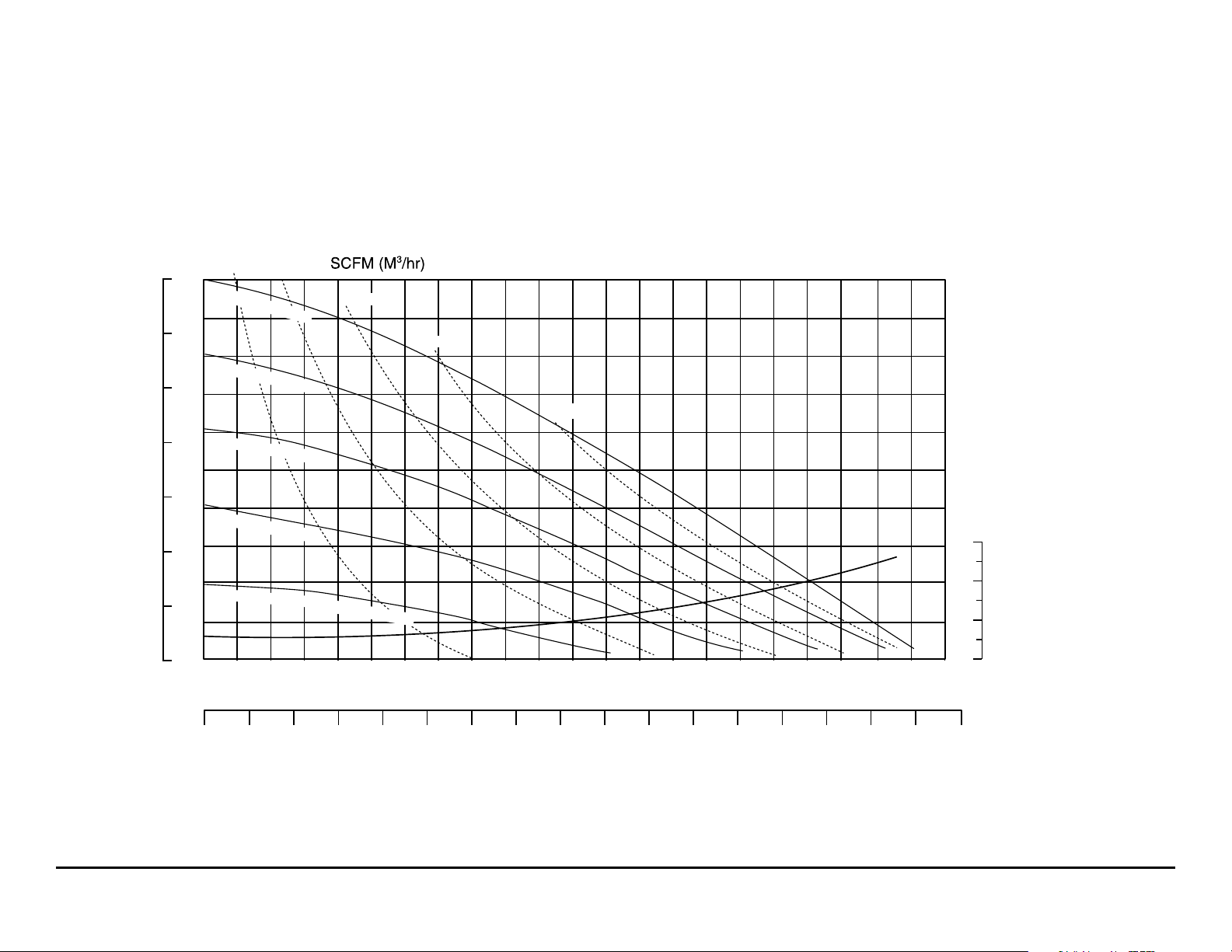
Performance Curve, M15 Metallic Design Level 1
MODEL S15 Metallic Performance Curve
Performance based on the following: elastomer tted pump, ooded suction, water at ambient conditions.
The use of other materials and varying hydraulic conditions may result in deviations in excess of 5%.
BAR
PSI
100
7
90
6
80
5
70
60
4
50
HEAD
3
40
30
2
20
1
10
0
10 (17)
100 PSI (6.8 Bar)
80 PSI (5.44 Bar)
60 PSI (4.08 Bar)
40 PSI (2.72 Bar)
20 PSI (1.36 Bar)
0
0
20 (34)
10
30 (51)
Air Inlet Pressure
20
40 (68)
50 (85)
30
40
50
70 80 90 100 11060
U.S. Gallons per minute
NPSHR
FEET
30
20
10
0
METERS
9.1
7.6
6
4.5
3
1.5
4254003753503253002752502252001751501251007550250
Liters per minute
CAPACITY
m15mdl1sm-rev0713 Model M15 Metallic Page 3
Page 6
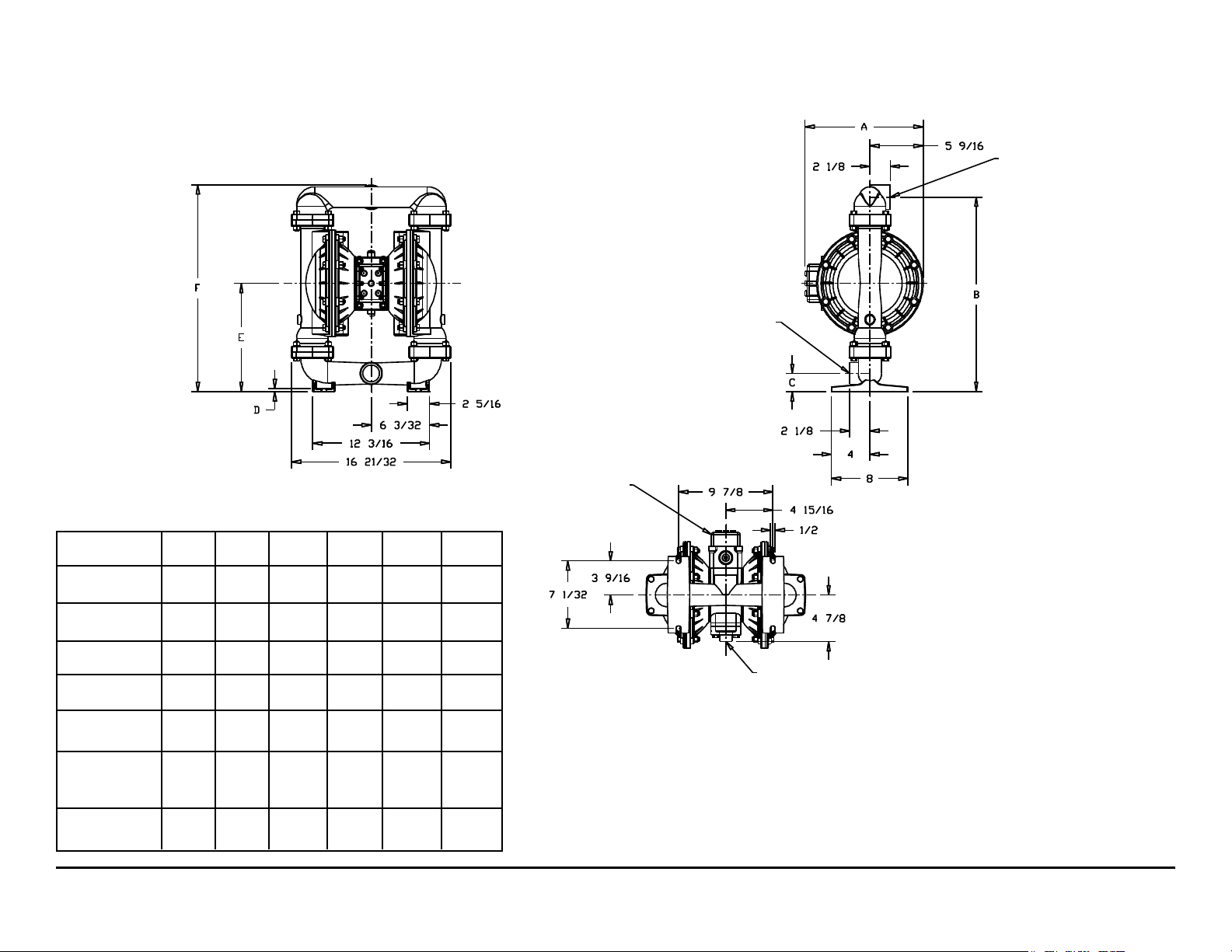
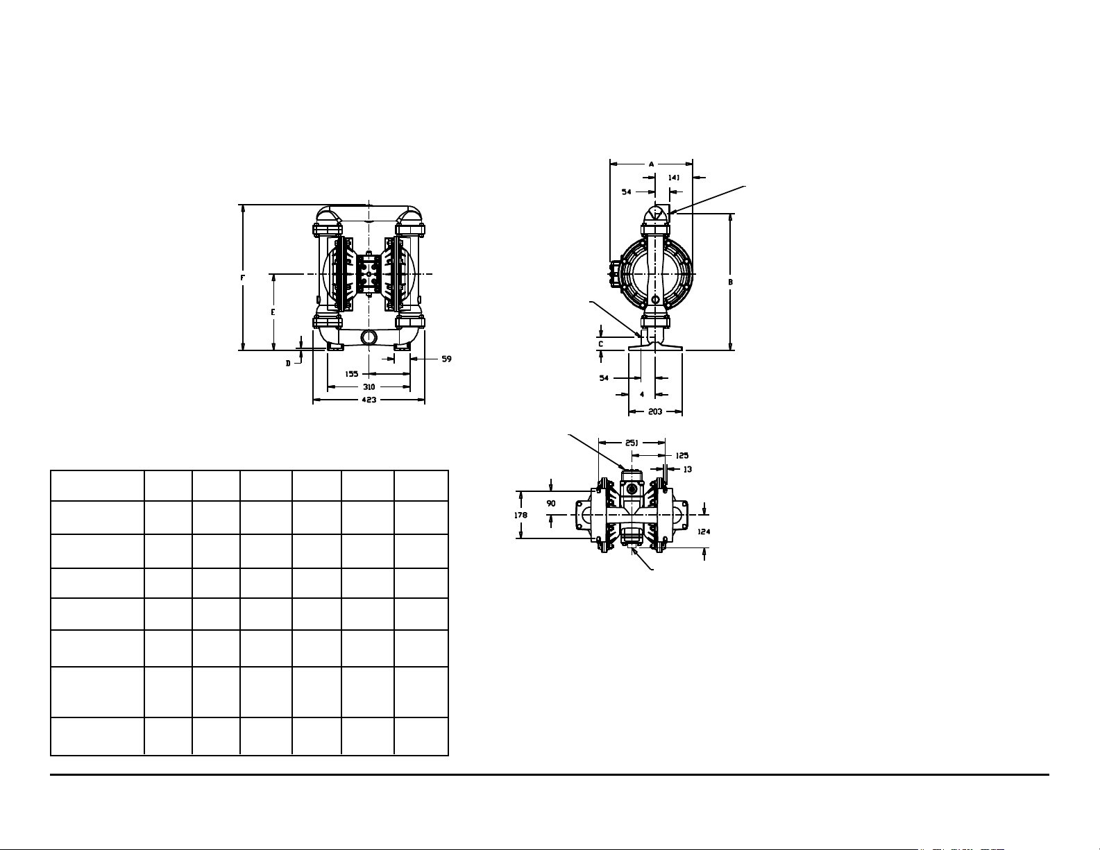
Dimensions: M15 Metallic
Dimensions in Inches
Dimensional Tolerance:±
Dimension
Integral Mufer
Pulse Output
Kit
A
12 11/32
12 11/32
1
/8"
B C D E
FRONT VIEW
Integral Muffler
1" NPT Exhaust Port
For optional Muffler
Styles or Piping Exhaust
Air In Sumerged
Applications.
F
Discharge Port
1 1/2" NPT
Suction Port
1 1/2" NPT
SIDE VIEW
Pump Shown
With 530-028-550
Integral Muffler
Both Suction and Discharge
Ports Are Available With
1 1/2" BSP Tapered Connection
BOTTOM VIEW
Aluminum
Stainless
Steel
Mesh
Mufer
Sound
Dampening
Mufer
Metal
Mufer
m15mdl1sm-rev0713 Model M15 Metallic Page 4
14 15/16
14 15/16
14 1/2
20 5/16 1 29/32 5/16
20 3/8 1 31/32 3/8
11 5/16
11 3/8
21 19/32
21 21/32
Air Inlet
3/4" NPT
Page 7
Metric Dimensions:
Dimensions in Millimeters
Dimensional Tolerance:± 3mm
Dimension
A
B C D E
FRONT VIEW
Suction Port
1 1/2" NPT
Integral Muffler
1" NPT Exhaust Port
For Optional Muffler
Styles or Piping Exhaust
Air in Submerged
Applications.
F
Discharge Port
1 1/2" NPT
SIDE VIEW
Pump Shown
With 530-028-550
Integral Muffler
Both Suction and Discharge
Ports Are Available With
1 1/2" BSP Tapered Connection
Integral Mufer
Pulse Output
Kit
Aluminum
Stainless
Steel
Mesh
Mufer
Sound
Dampening
Mufer
Metal
Mufer
m15mdl1sm-rev0713 Model M15 Metallic Page 5
314
314
379
379
368
516 48 8
518 50 10
287
289
548
550
BOTTOM VIEW
Air Inlet
3/4" NPT
Page 8

PRINCIPLE OF PUMP OPERATION
This ball type check valve pump
is powered by compressed air and is
a 1:1 ratio design. The inner side of
one diaphragm chamber is alternately
pressurized while simultaneously
exhausting the other inner chamber.
This causes the diaphragms, which
are connected by a common rod
secured by plates to the centers of the
diaphragms, to move in a reciprocating
action. (As one diaphragm performs the
discharge stroke the other diaphragm is
pulled to perform the suction stroke in
the opposite chamber.) Air pressure is
applied over the entire inner surface of
the diaphragm while liquid is discharged
from the opposite side of the diaphragm.
The diaphragm operates in a balanced
condition during the discharge stroke
which allows the pump to be operated
at discharge heads over 200 feet (61
meters) of water.
For maximum diaphragm life, keep
the pump as close to the liquid being
pumped as possible. Positive suction
head in excess of 10 feet of liquid
(3.048 meters) may require a back
pressure regulating device to maximize
diaphragm life.
Alternate pressurizing and
exhausting of the diaphragm chamber
is performed by an externally mounted,
pilot operated, four way spool type
air distribution valve. When the spool
shifts to one end of the valve body, inlet
pressure is applied to one diaphragm
chamber and the other diaphragm
chamber exhausts. When the spool
shifts to the opposite end of the valve
body, the pressure to the chambers
is reversed. The air distribution valve
spool is moved by a internal pilot valve
which alternately pressurizes one end
of the air distribution valve spool while
exhausting the other end. The pilot valve
is shifted at each end of the diaphragm
stroke when a actuator plunger is
contacted by the diaphragm plate. This
actuator plunger then pushes the end
of the pilot valve spool into position to
activate the air distribution valve.
The chambers are connected with
manifolds with a suction and discharge
check valve for each chamber,
maintaining flow in one direction
through the pump.
INSTALLATION AND START-UP
Locate the pump as close to the
product being pumped as possible.
Keep the suction line length and
number of ttings to a minimum. Do not
reduce the suction line diameter.
For installations of rigid piping,
short sections of exible hose should
be installed between the pump
and the piping. The flexible hose
reduces vibration and strain to the
pumping system. A MARATHON surge
suppressor is recommended to further
reduce pulsation in ow.
AIR SUPPLY
Air supply pressure cannot exceed
125 psi (8.6 bar). Connect the pump
air inlet to an air supply of sufcient
capacity and pressure required for
desired performance. When the air
supply line is solid piping, use a short
length of exible hose not less than ½"
(13mm) in diameter between the pump
and the piping to reduce strain to the
piping. The weight of the air supply line,
regulators and lters must be supported
by some means other than the air
inlet cap. Failure to provide support
for the piping may result in damage
to the pump. A pressure regulating
valve should be installed to insure
air supply pressure does not exceed
recommended limits.
AIR VALVE LUBRICATION
The air distribution valve and the
pilot valve are designed to operate
WITHOUT lubrication. This is the
preferred mode of operation. There may
be instances of personal preference
or poor quality air supplies when
lubrication of the compressed air
supply is required. The pump air system
will operate with properly lubricated
compressed air supply. Proper
lubrication requires the use of an air line
lubricator (available from MARATHON)
set to deliver one drop of SAE 10 non-
detergent oil for every 20 SCFM (9.4
liters/sec.) of air the pump consumes
at the point of operation. Consult the
pump’s published Performance Curve
to determine this.
AIR LINE MOISTURE
Water in the compressed air supply
can create problems such as icing or
freezing of the exhaust air, causing
the pump to cycle erratically or stop
operating. Water in the air supply can
be reduced by using a point-of-use
air dryer to supplement the user’s air
drying equipment. This device removes
water from the compressed air supply
and alleviates the icing or freezing
problems.
AIR INLET AND PRIMING
To start the pump, open the air valve
approximately 1/2" to 3/4" turn. After
the pump primes, the air valve can be
opened to increase air ow as desired.
If opening the valve increases cycling
rate, but does not increase the rate of
ow, cavitation has occurred. The valve
should be closed slightly to obtain the
most efcient air ow to pump ow ratio.
BETWEEN USES
When the pump is used for materials
that tend to settle out or solidify when
not in motion, the pump should be
flushed after each use to prevent
damage. (Product remaining in the
pump between uses could dry out or
settle out. This could cause problems
with the diaphragms and check valves
at restart.) In freezing temperatures
the pump must be completely drained
between uses in all cases.
m15mdl1sm-rev0713 Model M15 Metallic Page 6
Page 9
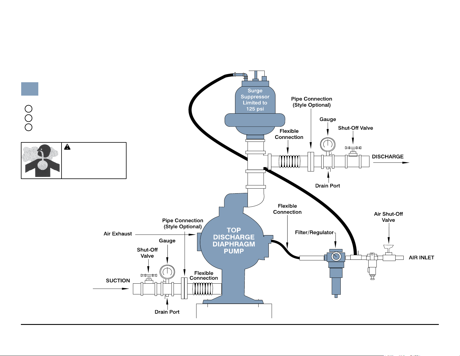
CAUTION
The ai r exhaust sh ou ld be
piped t o an area fo r safe
disposition of the product
bei ng pumped, in th e event
of a diaphragm fai lu re.
TYPICAL INSTALLATION GUIDE
For Metallic Pumps
Air Inlet
Line
Available from
MARATHON
1
MTA1½ or MTA40Surge Suppressor
2
020-050-000 Filter/Regulator
3
020-050-001 Lubricator
m15mdl1sm-rev0713 Model M15 Metallic Page 7
Page 10

TROUBLESHOOTING
Possible Symptoms:
• Pump will not cycle.
• Pump cycles, but produces no ow.
• Pump cycles, but ow rate is
unsatisfactory.
• Pump cycle seems unbalanced.
• Pump cycle seems to produce
excessive vibration.
What to Check: Excessive suction lift
in system.
Corrective Action: For lifts exceeding
20 feet (6 meters), lling the pumping
chambers with liquid will prime the
pump in most cases.
What to Check: Excessive flooded
suction in system.
Corrective Action: For flooded
conditions exceeding 10 feet (3 meters)
of liquid, install a back pressure device.
What to Check: System head exceeds
air supply pressure.
Corrective Action: Increase the
inlet air pressure to the pump. Most
diaphragm pumps are designed for 1:1
pressure ratio at zero ow.
What to Check: Air supply pressure or
volume exceeds system head.
Corrective Action: Decrease inlet
air pressure and volume to the pump
as calculated on the published
PERFORMANCE CURVE. Pump is
cavitating the uid by fast cycling.
What to Check: Undersized suction
line.
Corrective Action: Meet or exceed
pump connection recommendations
shown on the DIMENSIONAL
DRAWING.
What to Check: Restricted or
undersized air line.
Corrective Action: Install a larger
air line and connection. Refer to air
inlet recommendations shown in your
pump’s SERVICE MANUAL.
What to Check: Check ESADS+Plus,
the Externally Serviceable Air
Distribution System of the pump.
Corrective Action: Disassemble and
inspect the main air distribution valve,
pilot valve and pilot valve actuators.
Refer to the parts drawing and air valve
section of the SERVICE MANUAL.
Check for clogged discharge or closed
valve before reassembly.
What to Check: Rigid pipe connections
to pump.
Corrective Action: Install flexible
connectors and a MARATHON Surge
Suppressor.
What to Check: Blocked air exhaust
mufer.
Corrective Action: Remove mufer
screen, clean or de-ice and reinstall.
Refer to the Air Exhaust section of your
pump SERVICE MANUAL.
What to Check: Pumped uid in air
exhaust mufer.
Corrective Action: Disassemble pump
chambers. Inspect for diaphragm rupture
or loose diaphragm plate assembly. Refer
to the Diaphragm Replacement section
of your pump SERVICE MANUAL.
What to Check: Suction side air leakage
or air in product.
Corrective Action: Visually inspect
all suction side gaskets and pipe
connections.
What to Check: Obstructed check
valve.
Corrective Action: Disassemble the wet
end of the pump and manually dislodge
obstruction in the check valve pocket.
Refer to the Check Valve section of
the pump SERVICE MANUAL for
disassembly instructions.
What to Check: Worn or misaligned
check valve or check valve seat.
Corrective Action: Inspect check
valves and seats for wear and proper
seating. Replace if necessary. Refer
to Check Valve section of the pump
SERVICE MANUAL for disassembly
instructions.
What to Check: Blocked suction line.
Corrective Action: Remove or ush
obstruction. Check and clear all suction
screens and strainers.
What to Check: Blocked discharge
line.
Corrective Action: Check for
obstruction or closed discharge line
valves.
What to Check: Blocked pumping
chamber.
Corrective Action: Disassemble
and inspect the wetted chambers
of the pump. Remove or flush any
obstructions. Refer to the pump
SERVICE MANUAL for disassembly
instructions.
What to Check: Entrained air or vapor
lock in one or both pumping chambers.
Corrective Action: Purge chambers
through tapped chamber vent plugs.
PURGING THE CHAMBERS OF AIR
CAN BE DANGEROUS! Contact the
MARATHON Technical Services Group
before performing this procedure. Any
model with top-ported discharge will
reduce or eliminate problems with
entrained air.
If your pump continues to perform
below your expectations, contact your
local MARATHON Distributor or factory
Technical Services Group for a service
evaluation.
WARRANTY
Refer to the enclosed MARATHON
Warranty Certicate.
m15mdl1sm-rev0713 Model M15 Metallic Page 8
Page 11
Recycling
Many components of MARATHON®
Metallic AODD pumps are made of
recyclable materials (see chart on
page 10 for material specications).
We encourage pump users to recycle
worn out parts and pumps whenever
possible, after any hazardous pumped
uids are thoroughly ushed.
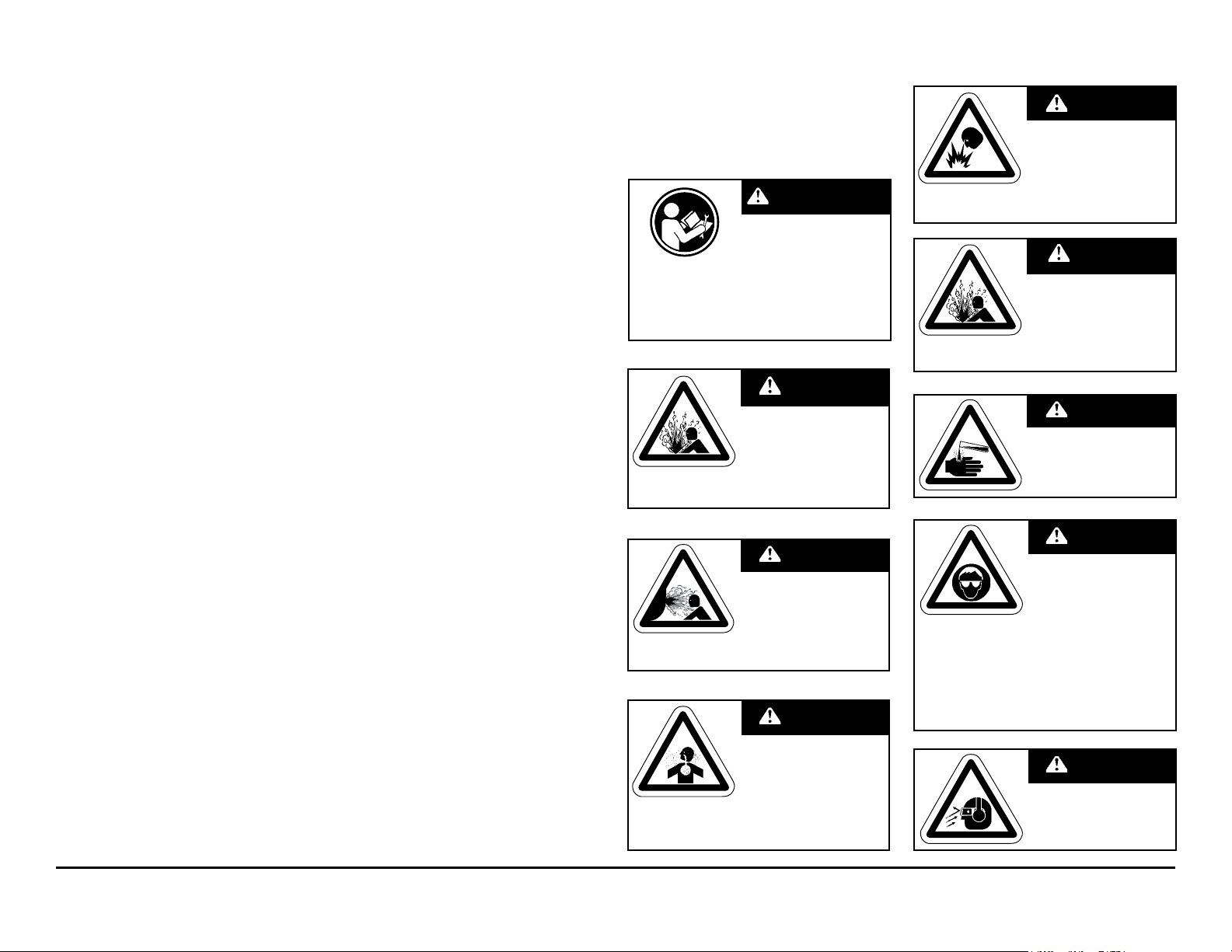
IMPORTANT SAFETY
INFORMATION
IMPORTANT
Read these safety warnings
Read these safety warnings
and instructions in this
and instructions in this
manual completely, before
manual completely, before
installation and start-up
of the pump. It is the responsibility of the
of the pump. It is the responsibility of the
purchaser to retain this manual for reference.
purchaser to retain this manual for reference.
Failure to comply with the recommendations
Failure to comply with the recommendations
stated in this manual will damage the pump,
stated in this manual will damage the pump,
and void factory warranty.
and void factory warranty.
prevent leakage. Follow recommended torques
stated in this manual.
from the pump. The discharge line may be
pressurized and must be bled of its pressure.
pumping a product which is hazardous or toxic,
the air exhaust must be piped to an appropriate
area for safe disposition.
installation and start-up
CAUTION
Before pump operation,
inspect all gasketed
fasteners for looseness
caused by gasket creep. Re-
torque loose fasteners to
WARNING
Before maintenance
or repair, shut off the
compressed air line,
bleed the pressure, and
disconnect the air line
WARNING
In the event of diaphragm
rupture, pumped material
may enter the air end of the
pump, and be discharged
into the atmosphere. If
WARNING
Take action to prevent static
sparking. Fire or explosion
can result, especially when
handling ammable liquids.
containers or other miscellaneous equipment
must be grounded. (See page 28)
The pump, piping, valves,
WARNING
This pump is pressurized
internally with air pressure
during operation. Always
make certain that all bolting
is in good condition and
bolting is reinstalled during assembly.
that all of the correct
WARNING
When used for toxic or
aggressive uids, the pump
should always be ushed
clean prior to disassembly.
WARNING
Before doing any
maintenance on the pump,
be certain all pressure is
completely vented from the
pump, suction, discharge,
openings and connections. Be certain the air
supply is locked out or made non-operational,
so that it cannot be started while work is being
done on the pump. Be certain that approved
eye protection and protective clothing are worn
all times in the vicinity of the pump. Failure to
follow these recommendations may result in
serious injury or death.
piping, and all other
WARNING
Airborne particles and
loud noise hazards.
Wear ear and eye
protection.
m15mdl1sm-rev0713 Model M15 Metallic Page 9
Page 12

Material Codes
The Last 3 Digits of Part Number
000 Assembly, sub-assembly;
and some purchased items
010 Cast Iron
012 Powered Metal
015 Ductile Iron
020 Ferritic Malleable Iron
025 Music Wire
080 Carbon Steel, AISI B-1112
100 Alloy 20
110 Alloy Type 316 Stainless Steel
111 Alloy Type 316 Stainless Steel
(Electro Polished)
112 Alloy C
113 Alloy Type 316 Stainless Steel
(Hand Polished)
114 303 Stainless Steel
115 302/304 Stainless Steel
117 440-C Stainless Steel (Martensitic)
120 416 Stainless Steel
(Wrought Martensitic)
123 410 Stainless Steel
(Wrought Martensitic)
148 Hardcoat Anodized Aluminum
149 2024-T4 Aluminum
150 6061-T6 Aluminum
151 6063-T6 Aluminum
152 2024-T4 Aluminum (2023-T351)
154 Almag 35 Aluminum
155 356-T6 Aluminum
156 356-T6 Aluminum
157 Die Cast Aluminum Alloy #380
158 Aluminum Alloy SR-319
159 Anodized Aluminum
162 Brass, Yellow, Screw Machine Stock
165 Cast Bronze, 85-5-5-5
166 Bronze, SAE 660
170 Bronze, Bearing Type,
Oil Impregnated
175 Die Cast Zinc
180 Copper Alloy
305 Carbon Steel, Black Epoxy Coated
306 Carbon Steel, Black PTFE Coated
307 Aluminum, Black Epoxy Coated
308 Stainless Steel, Black PTFE Coated
309 Aluminum, Black PTFE Coated
310 PVDF Coated
330 Zinc Plated Steel
331 Chrome Plated Steel
332 Aluminum, Electroless Nickel Plated
333 Carbon Steel, Electroless
Nickel Plated
335 Galvanized Steel
336 Zinc Plated Yellow Brass
337 Silver Plated Steel
340 Nickel Plated
342 Filled Nylon
353 Geolast; Color: Black
354 Injection Molded #203-40 Santoprene-
Duro 40D +/-5; Color: RED
355 Thermal Plastic
356 Hytrel
357 Injection Molded Polyurethane
358 Urethane Rubber
(Some Applications) (Compression Mold)
359 Urethane Rubber
360 Nitrile Rubber. Color coded: RED
361 FDA Accepted Nitrile
363 FKM (Fluorocarbon).
Color coded: YELLOW
364 E.P.D.M. Rubber. Color coded: BLUE
365 Neoprene Rubber.
Color coded: GREEN
366 Food Grade Nitrile
368 Food Grade EPDM
370 Butyl Rubber. Color coded: BROWN
371 Philthane (Tuftane)
374 Carboxylated Nitrile
375 Fluorinated Nitrile
378 High Density Polypropylene
379 Conductive Nitrile
405 Cellulose Fibre
408 Cork and Neoprene
425 Compressed Fibre
426 Blue Gard
440 Vegetable Fibre
465 Fibre
500 Delrin 500
501 Delrin 570
502 Conductive Acetal, ESD-800
503 Conductive Acetal, Glass-Filled
505 Acrylic Resin Plastic
506 Delrin 150
520 Injection Molded PVDF Natural color
521 Conductive PVDF
540 Nylon
541 Nylon
542 Nylon
544 Nylon Injection Molded
550 Polyethylene
551 Glass Filled Polypropylene
552 Unlled Polypropylene
553 Unlled Polypropylene
555 Polyvinyl Chloride
556 Black Vinyl
557 Conductive Polypropylene
558 Conductive HDPE
559 Glass-Filled Conductive Polypropylene
570 Rulon II
580 Ryton
590 Valox
591 Nylatron G-S
592 Nylatron NSB
600 PTFE (virgin material)
Tetrauorocarbon (TFE)
601 PTFE (Bronze and moly lled)
602 Filled PTFE
603 Blue Gylon
604 PTFE
606 PTFE
607 Envelon
608 Conductive PTFE
610 PTFE Integral Silicon
611 PTFE Integral FKM
632 Neoprene/Hytrel
633 FKM (Fluorocarbon)/PTFE
634 EPDM/PTFE
635 Neoprene/PTFE
637 PTFE, FKM (Fluorocarbon)/PTFE
638 PTFE, Hytrel/PTFE
639 Nitrile/TFE
643 Santoprene/EPDM
644 Santoprene/PTFE
650 Bonded Santoprene and PTFE
654 Santoprene Diaphragm, PTFE Overlay
Balls and seals
656 Santoprene Diaphragm and
Check Balls/EPDM Seats
661 EPDM/Santoprene
Delrin and Hytrel are registered tradenames
of E.I. DuPont.
Gylon is a registered tradename of Garlock, Inc.
Nylatron is a registered tradename of
Polymer Corp.
Santoprene is a registered tradename of
Exxon Mobil Corp.
Rulon II is a registered tradename of
Dixion Industries Corp.
Ryton is a registered tradename of
Phillips Chemical Co.
Valox is a registered tradename of
General Electric Co.
MARATHON, Portapump and SludgeMaser are
registered tradenames of Warren Rupp, Inc.
m15mdl1sm-rev0713 Model M15 Metallic Page 10
Page 13

m15mdl1sm-rev0713 Model M15 Metallic Page 11
Page 14

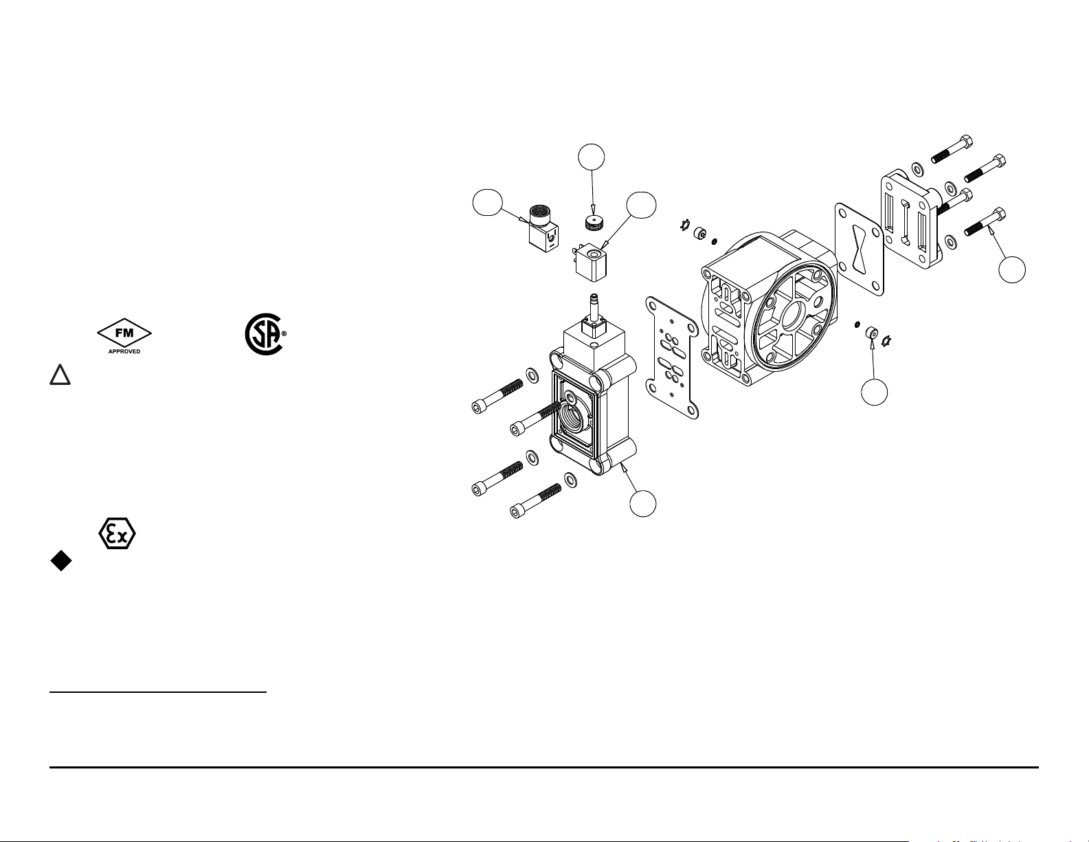
Composite Repair Parts Drawing
Torque
90 in. lbs.
Torque:
Plate to Rod
360 in. lbs.
Torque: Plate to Plate
480 in. lbs.
600 in. lbs. Santoprene
Torque:
360 in. lbs. Aluminum
and Stainless Steel,
500 in. lbs. Cast Iron
Torque
90 in. lbs.
Overlay Diaphragm Option
One-Piece Bonded
Diaphragm Option
AVAILABLE SERVICE AND CONVERSION KITS
476-227-000 AIR END KIT (Use With Aluminum Center)
Air Valve Assembly, Pilot Valve Assembly, Seals, Bumpers,
Gaskets, Plunger and O-rings.
476-227-010 AIR END KIT (Use With Cast Iron Centers)
476-227-110 AIR END KIT (Use With Stainless Steel Centers)
476-170-558 AIR END KIT (Air Valve with Stroke Indicator Pin, Aluminum Center)
Seals, O-ring, Gaskets, Retaining Rings, Air Valve
Sleeve and Spool Set, and Pilot Valve Assembly.
476-182-360 WET END KIT
Nitrile Diaphragms, Balls, and Polyethylene Seats.
476-182-354 WET END KIT
Santoprene Diaphragms, Balls and Polyethylene Seats.
476-182-365 WET END KIT
Neoprene Diaphragms, Balls, and Polyethylene Seats.
476-182-633 WET END KIT
FKM Diaphragms, PTFE Balls and Seats.
476-182-635 WET END KIT
Neoprene Diaphragms, PTFE Overlay, Balls and Seats.
476-182-364 WET END KIT
EPDM Diaphragms, Balls and UHMW Seats.
476-182-654 WET END KIT
Santoprene Diaphragms, PTFE Overlay, PTFE Balls,
PTFE Seats.
476-182-659 WETTED END KIT
One-PIece Bonded PTFE/Nitrile Diaphragm,
PTFE Balls, PTFE Seats.
475-215-000 MIDSECTION CONVERSION KIT
(Replaces Aluminum Midsection With Cast Iron
Components.) Air Inlet Cap, Intermediate Bracket,
Inner Chambers and Inner Diaphragm Plates.
HARDWARE KITS
475-205-330 Zinc Plated Capscrews, Washers, and Hex Nuts
475-205-115 Stainless Steel Capscrews, Washers, and Hex Nuts
**ELECTRONIC LEAK DETECTOR KITS
032-040-000 100VAC
032-037-000 220VAC
**Note: Pumps equipped with these components are not ATEX compliant.
m15mdl1sm-rev0713 Model M15 Metallic Page 12
Page 15

Composite Repair Parts List
I M2 c T5
II 2GD T5
ITEM PART NUMBER DESCRIPTION QTY
1 031-140-000 Air Valve Assembly w/Integral mufer (Cast Iron Centers Only) 1
031-141-000 Air Valve Assembly (Cast Iron Centers Only) 1
031-146-000 Air Valve Assembly w/Integral mufer (Stroke Indicator Only) 1
031-147-000 Air Valve Assembly (Stroke Indicator Only) 1
031-173-000 Air Valve Assembly w/Integral mufer 1
031-173-001 Air Valve Assembly (with Stainless Steel Hardware) 1
031-183-000 Air Valve Assembly 1
031-179-000 Air Valve Assembly (
2 050-005-354 Ball, Check 4
050-005-360 Ball, Check 4
050-005-360W Ball, Weighted Check 4
050-005-363 Ball, Check 4
050-005-364 Ball, Check 4
050-005-365 Ball, Check 4
050-005-365W Ball, Weighted Check 4
050-010-600 Ball, Check 4
3 070-006-170 Bushing 2
4 095-110-000 Pilot Valve Assembly 1
095-110-558 Pilot Valve Assembly (Cast Iron Centers Only) 1
095-095-110 Pilot Valve Assembly (Stainless Steel Centers Only) 1
5 114-024-157 Intermediate Bracket 1
114-024-010 Intermediate Bracket 1
114-024-110 Intermediate Bracket (Stainless Steel Centers Only) 1
6 132-035-360 Bumper, Diaphragm 2
7 135-034-506 Bushing, Plunger 2
8 165-118-157 Cap, Air Inlet Assembly 1
165-118-010 Cap, Air Inlet Assembly 1
165-118-110 Cap, Air Inlet Assembly (Stainless Steel Centers Only) 1
9 170-060-115 Capscrew, Hex Hd 7/16-14 X 2.00 16
170-060-330 Capscrew, Hex Hd 7/16-14 X 2.00 16
10 170-061-115 Capscrew, Hex Hd 3/8-16 X 1.75 16
170-061-330 Capscrew, Hex Hd 3/8-16 X 1.75 16
11 170-069-115 Capscrew, Hex Hd 5/16-18 X 1.75 4
170-069-330 Capscrew, Hex Hd 5/16-18 X 1.75 4
12 170-006-115 Capscrew, Hex HD 3/8-16 X 1.00 4
170-006-330 Capscrew, Hex HD 3/8-16 X 1.00 4
171-053-115 Capscrew, Soc Hd 3/8-16 X 2.50 (Stroke Indicator Only) 4
171-053-330 Capscrew, Soc Hd 3/8-16 X 2.50 (Stroke Indicator Only) 4
171-011-115 Capscrew, Soc Hd 1/2-13 x 1.00 (Stainless Center) 8
13 171-059-115 Capscrew, Soc Hd 7/16-14 X 1.25 8
171-059-330 Capscrew, Soc Hd 7/16-14 X 1.25 8
14 196-169-156 Chamber, Outer 2
196-169-010 Chamber, Outer 2
196-169-110 Chamber, Outer 2
15 196-170-157 Chamber, Inner 2
196-170-010 Chamber, Inner 2
196-170-110 Chamber, Inner 2
16 286-099-354 Diaphragm 2
286-099-360 Diaphragm 2
286-099-363 Diaphragm 2
286-099-364 Diaphragm 2
286-099-365 Diaphragm 2
17 286-099-600 Diaphragm, Overlay 2
286-113-000 Diaphragm, One-Piece Bonded 2
18 360-093-360 Gasket, Air Valve 1
Cast Iron or Stainless Steel Centers Only) 1
ATEX Compliant
ITEM PART NUMBER DESCRIPTION QTY
19 360-114-360 Gasket, Pilot Valve 1
20 360-104-379 Gasket, Air Inlet 1
21 360-105-360 Gasket, Inner Chamber 2
22 518-151-156 Manifold, Suction 1
518-151-156E Manifold, Suction 1-1/2" BSP Tapered 1
518-151-010 Manifold, Suction 1
518-151-010E Manifold, Suction 1-1/ 2" BSP Tapered 1
518-151-110 Manifold, Suction 1
518-151-110E Manifold, Suction 1-1/ 2" BSP Tapered 1
23 518-152-156 Manifold, Discharge 1
518-152-156E Manifold, Discharge 1-1/ 2" BSP Tapered 1
518-152-010 Manifold, Discharge 1
518-152-010E Manifold, Discharge 1-1/ 2" BSP Tapered 1
518-152-110 Manifold, Discharge 1
518-152-110E Manifold, Discharge 1-1/ 2" BSP Tapered 1
24 545-005-115 Nut, Hex 3/8-16 16
545-005-330 Nut, Hex 3/8-16 16
25 545-007-115 Nut, Hex 7/16-14 16
545-007-330 Nut, Hex 7/16-14 16
26 560-001-379 O-Ring 2
27 560-084-360 Seal (O-Ring) (See item 34) 8
560-084-363 Seal (O-Ring) (See item 34) 8
560-084-364 Seal (O-Ring) (See item 34) 8
560-084-365 O-Ring 8
720-061-608 Seal (O-Ring) (See item 34) 8
28 612-039-157 Plate, Outer Diaphragm Assembly 2
612-039-010 Plate, Outer Diaphragm Assembly 2
612-097-110 Plate, Outer Diaphragm Assembly 2
29 612-195-157 Plate, Inner Diaphragm 2
612-195-010 Plate, Inner Diaphragm 2
612-217-150 Plate, Inner Diaphragm (use with one-piece diaphragm) 2
30 620-020-115 Plunger, Actuator 2
31 675-042-115 Ring, Retaining 2
32 685-059-120 Rod, Diaphragm 1
33 720-004-360 Seal, Diaphragm Rod 2
34 722-091-550 Seat, Check Ball 4
722-091-080 Seat, Check Ball (seals required see item 27) 4
722-091-110 Seat, Check Ball (seals required see item 27) 4
722-091-150 Seat, Check Ball (seals required see item 27) 4
722-091-600 Seat, Check Ball 4
35 901-038-115 Washer, Flat 5/16 4
901-038-330 Washer, Flat 5/16 4
36 901-048-115 Washer, Flat 3/8 (Stroke Indicator Only) 4
901-048-330 Washer, Flat 3/8 (Stroke Indicator Only) 4
37 570-009-363 Pad, Wear (use with #286-099-363) 2
43 530-033-000 Metal Mufer (for other mufer options see pg. 24) 1
Parts not shown used with Raised Face Flange Porting Option.
170-035-330 Hex Cap Screw 4
326-051-080 Mounting Bracket 2
334-113-110 1½" Raised Face, 150# ANSI Flange 2
538-036-110 Pipe Nipple 1½" NPT x 2" 2
545-005-330 Hex Nut 4
900-006-330 Lock Washer 4
901-022-330 Flat Washer 8
m15mdl1sm-rev0713 Model M15 Metallic Page 13
Page 16
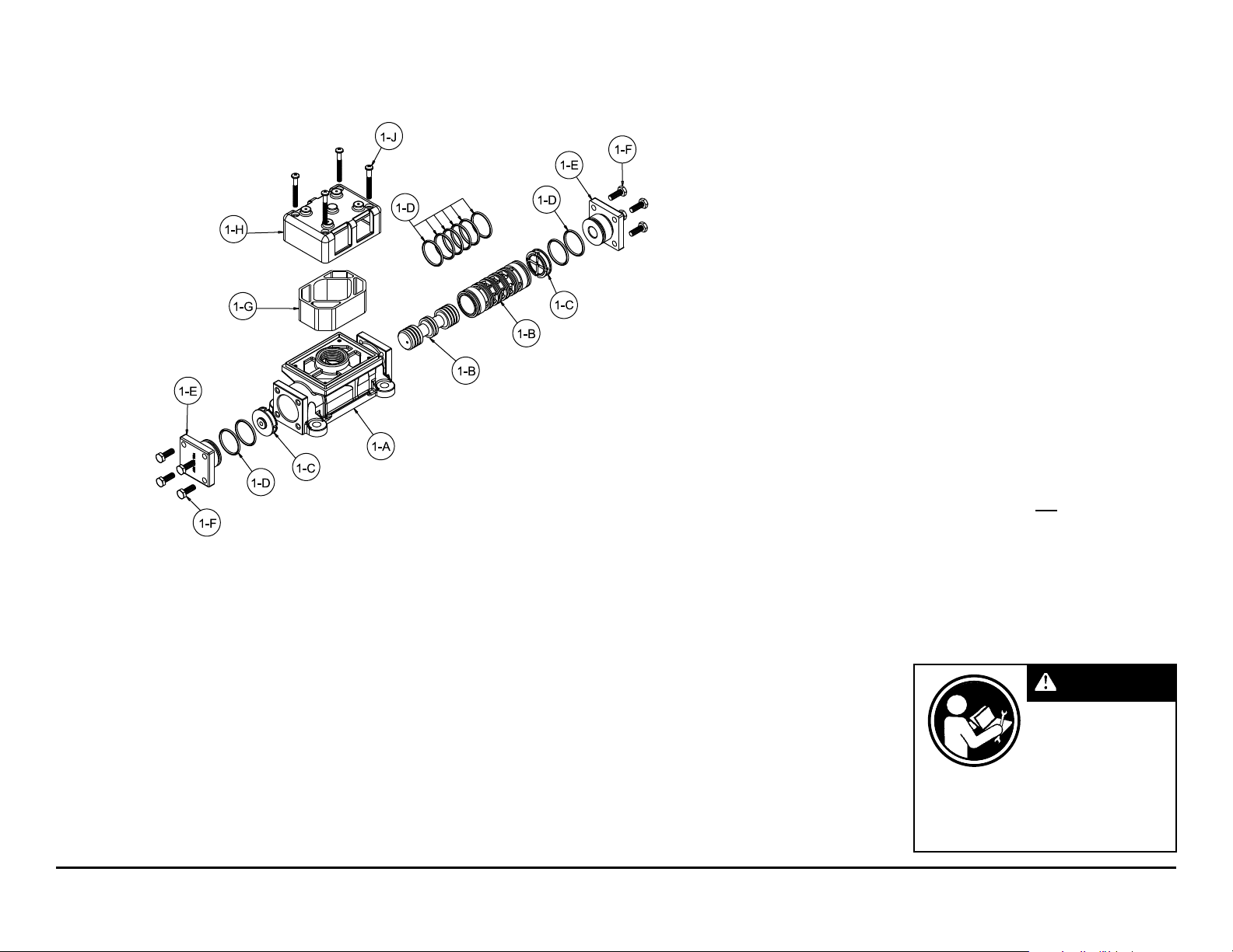
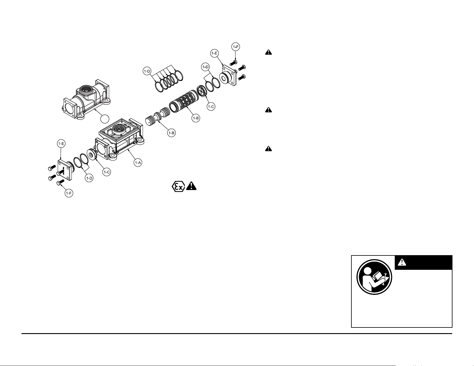
Air Valve Servicing, Assembly Drawing
& Parts List
(Use With Aluminum Centers Only)
**AIR VALVE ASSEMBLY PARTS LIST
Item Part Number Description Qty
1 031-173-000 Air Valve Assembly 1
1-A 095-109-157 Body, Air Valve 1
1-B 031-139-000 Sleeve and Spool Set 1
1-C 132-029-357 Bumper 2
1-D 560-020-360 O-Ring 10
1-E 165-127-157 Cap, End 2
1-F 170-032-330 Hex Head Capscrew 1/4-20 x .75 8
1-G 530-028-550 Mufer 1
1-H 165-096-551 Mufer Cap 1
1-J 706-026-330 Machine Screw 4
**AIR VALVE ASSEMBLY PARTS LIST
1 031-173-001 Air Valve Assembly 1
Consists of all components above except:
1-F 170-032-115 Hex Head Capscrew 1/4-20 x .75 8
1-J 706-026-115 Machine Screw 4
**Note: Pumps equipped with this valve assembly are not ATEX compliant.
AIR DISTRIBUTION VALVE SERVICING
To service the air valve rst shut off the
compressed air, bleed pressure from the
pump, and disconnect the air supply line
from the pump.
Step #1: See COMPOSITE REPAIR PARTS
DRAWING.
Using a 9/16" wrench or socket, remove
the four hex capscrews (items 12). Remove
the air valve assembly from the pump.
Remove and inspect gasket (item 18)
for cracks or damage. Replace gasket if
needed.
Step #2: Disassembly of the air valve.
Using a 7/16" wrench or socket, remove
the eight hex capscrews (items 1-F) that
m15mdl1sm-rev0713 Model M15 Metallic Page 14
fasten the end caps to the valve body.
Next remove the two end caps (items 1-E).
Inspect the two o-rings (items 1-D) on each
end cap for damage or wear. Replace the
bumpers as needed.
Remove the bumpers (items 1-C).
Inspect the bumpers for damage or wear.
Replace the bumpers as needed.
Remove the spool (part of item 1-B)
from the sleeve. Be careful not to scratch
or damage the outer diameter of the spool.
Wipe spool with a soft cloth and inspect for
scratches or wear.
Inspect the inner diameter of the sleeve
(part of item 1-B) for dirt, scratches, or other
contaminants. Remove the sleeve if needed
and replace with a new sleeve and spool
set (item 1-B).
Step #3: Reassembly of the air valve.
Install one bumper (item 1-C) and one
end cap (item 1-E), with two o-rings (items
1-D), and fasten with four hex capscrews
(items 1-F) to the valve body (item 1-A).
Remove the new sleeve an spool set
(item 1-B) from the plastic bag. Carefully
remove the spool from the sleeve. Install the
six o-rings (item 1-D) into the six grooves
on the sleeve. Apply a light coating of
grease to the o-rings before installing the
sleeve into the valve body (item 1-A), align
the slots in the sleeve with the slots in the
valve body. Insert the spool into the sleeve.
Be careful not to scratch or damage the
spool during installation. Carefully insert
the sleeve into the bumper and end cap
(with o-rings) and fasten with the remaining
hex capscrews.
Fasten the air valve assembly (item
1) and gasket to the pump. Connect the
compressed air line to the pump. The pump
is now ready for operation.
IMPORTANT
Read these instructions
completely, before
installation and
start-up. It is the
responsibility of the
purchaser to retain this
manual for reference. Failure to comply
with the recommendations stated in this
manual will damage the pump, and void
factory warranty.
Page 17
Air Valve Servicing, Assembly Drawing
I M2 c T5
II 2GD T5
& Parts List
1-A
*
Note: Cannot be
*
used with Integral
Mufer option 0.
ATEX Compliant
AIR VALVE ASSEMBLY PARTS LIST
(Use w/Aluminum centers only)
Item Part Number Description Qty
1 031-183-000 Air Valve Assembly 1
1-A 095-109-157 Body, Air Valve 1
1-B 031-139-000 Sleeve and Spool Set 1
1-C 132-029-357 Bumper 2
1-D 560-020-360 O-Ring 10
1-E 165-127-157 Cap, End 2
1-F 170-032-330 Hex Head Capscrew 1/4-20 x .75 8
AIR VALVE ASSEMBLY PARTS LIST
1 031-183-001 Air Valve Assembly 1
Consists of all components above except:
1-F 170-032-115 Hex Head Capscrew 1/4-20 x .75 8
AIR VALVE ASSEMBLY PARTS LIST
(Use w/Cast Iron and Stainless Steel centers only)
Item Part Number Description Qty
1 031-179-000 Air Valve Assembly 1
1-A 095-109-110 Body, Air Valve 1
1-B 031-139-000 Sleeve and Spool Set 1
1-C 132-029-357 Bumper 2
1-D 560-020-379 O-Ring 10
1-E 165-127-110 Cap, End 2
1-F 170-032-115 Hex Head Capscrew 1/4-20 x .75 8
*
AIR DISTRIBUTION VALVE SERVICING
To service the air valve rst shut off the
compressed air, bleed pressure from the
pump, and disconnect the air supply line
from the pump.
Step #1: See COMPOSITE REPAIR PARTS
DRAWING.
Using a 9/16" wrench or socket, remove
the four hex capscrews (items 12). Remove
the air valve assembly from the pump.
Remove and inspect gasket (item 18)
for cracks or damage. Replace gasket if
needed.
Step #2: Disassembly of the air valve.
Using a 7/16" wrench or socket, remove
the eight hex capscrews (items 1-F) that
m15mdl1sm-rev0713 Model M15 Metallic Page 15
fasten the end caps to the valve body.
Next remove the two end caps (items 1-E).
Inspect the two o-rings (items 1-D) on each
end cap for damage or wear. Replace the
o-rings as needed.
Remove the bumpers (items 1-C).
Inspect the bumpers for damage or wear.
Replace the bumpers as needed.
Remove the spool (part of item 1-B)
from the sleeve. Be careful not to scratch
or damage the outer diameter of the spool.
Wipe spool with a soft cloth and inspect for
scratches or wear.
Inspect the inner diameter of the sleeve
(part of item 1-B) for dirt, scratches, or other
contaminants. Remove the sleeve if needed
and replace with a new sleeve and spool
set (item 1-B).
Step #3: Reassembly of the air valve.
Install one bumper (item 1-C) and one
end cap (item 1-E), with two o-rings (items
1-D), and fasten with four hex capscrews
(items 1-F) to the valve body (item 1-A).
Remove the new sleeve an spool set
(item 1-B) from the plastic bag. Carefully
remove the spool from the sleeve. Install the
six o-rings (item 1-D) into the six grooves
on the sleeve. Apply a light coating of
grease to the o-rings before installing the
sleeve into the valve body (item 1-A), align
the slots in the sleeve with the slots in the
valve body. Insert the spool into the sleeve.
Be careful not to scratch or damage the
spool during installation. Carefully insert
the sleeve into the bumper and end cap
(with o-rings) and fasten with the remaining
hex capscrews.
Fasten the air valve assembly (item
1) and gasket to the pump. Connect the
compressed air line to the pump. The pump
is now ready for operation.
IMPORTANT
Read these instructions
completely, before
installation and
start-up. It is the
responsibility of the
purchaser to retain
this manual for reference. Failure to
comply with the recommendations
stated in this manual will damage the
pump, and void factory warranty.
Page 18
1-J
1-D
1-F
1-G
1-H
1-G
1-E
1-C
1-A
1-A
1-B
1-C
1-E
1-G
1-H
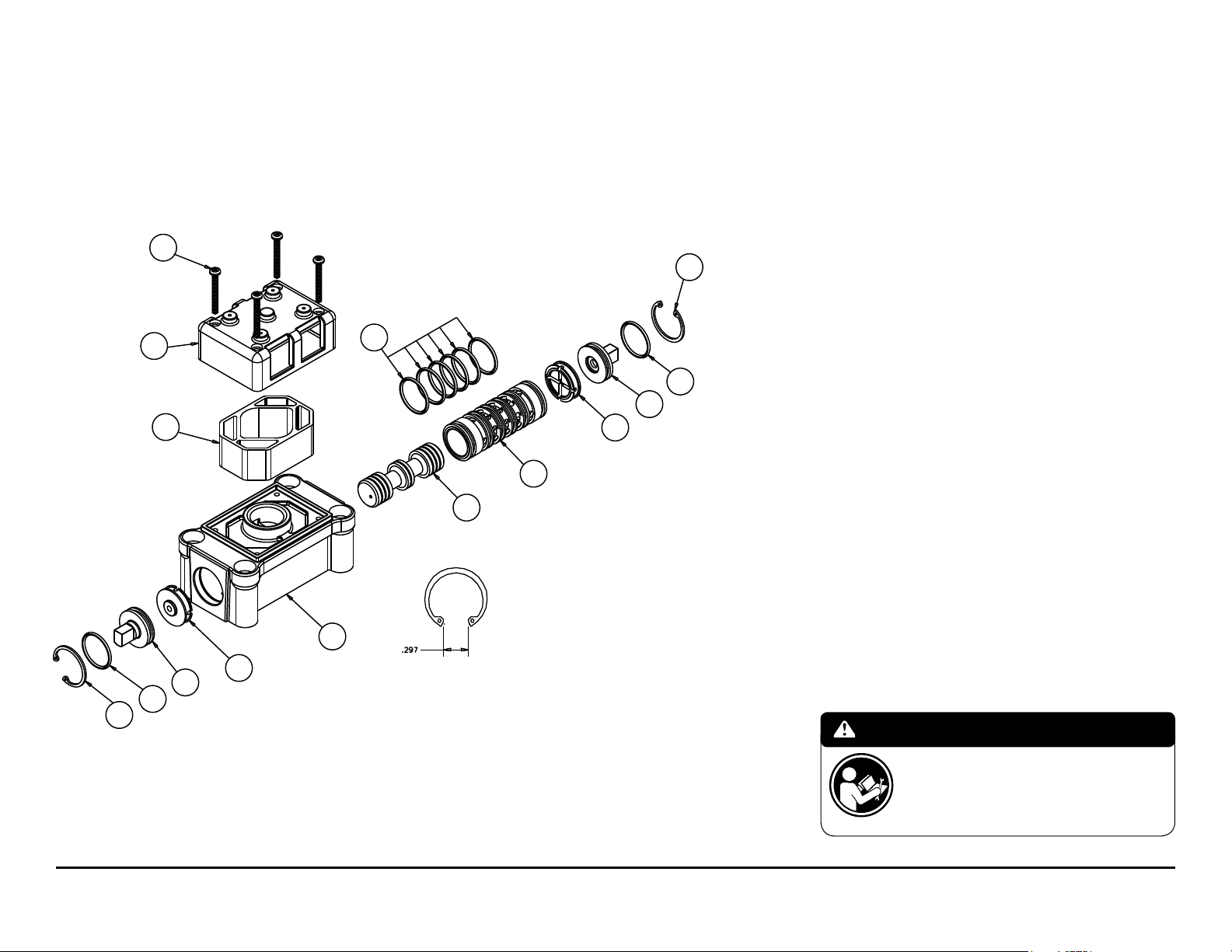
Air Distribution Valve Assembly
NOTE: CHECK GAP AFTER ASSEMBLY
TO INSURE COMPLETE
INSTALLATION OF RETAINING RING
(For Non-ATEX Cast Iron Centers)
Air Distribution Valve Servicing
See repair parts drawing, remove screws.
Step 1: Remove end cap retainer (1-H).
Step 2: Remove end cap (1-E).
Step 3: Remove spool part of (1-A) (caution: do not scratch).
Step 4: Press sleeve (1-A) from body (1-B).
Step 5: Inspect O-Ring (1-H) and replace if necessary.
Step 6: Lightly lubricate O-Rings (1-H) on sleeve (1-A).
Step 7: Press sleeve (1-A) into body (1-B).
Step 8: Reassemble in reverse order, starting with step 3.
Note: Sleeve and spool (1-A) set is match ground to a specied clearance
sleeve and spools (1-A) cannot be interchanged.
Air Valve Assembly Parts List
Item Part Number Description Qty
1 031-140-000 Air Valve Assembly 1
1-A 031-139-000 Sleeve and Spool Set 1
1-B 095-094-551 Body, Air Valve 1
1-C 132-029-552 Bumper 2
1-D 165-096-551 Cap, Mufer 1
1-E 165-115-558 Cap, End 2
1-F 530-028-550 Mufer 1
1-G 560-020-360 O-Ring 8
1-H 675-044-115 Ring, Retaining 2
1-J 710-015-115 Screw, Self-tapping 4
For Pumps with Alternate Mesh, Sound Dampening Mufers or Piped Exhaust:
1 031-141-000 Air Valve Assembly 1
(Includes all items used on 031-140-000
minus items 1-D, 1-F & 1-J)
IMPORTANT
Read these instructions completely, before installation
and start-up. It is the responsibility of the purchaser
m15mdl1sm-rev0713 Model M15 Metallic Page 16
to retain this manual for reference. Failure to comply
with the recommendations stated in this manual will
damage the pump, and void factory warranty.
Page 19
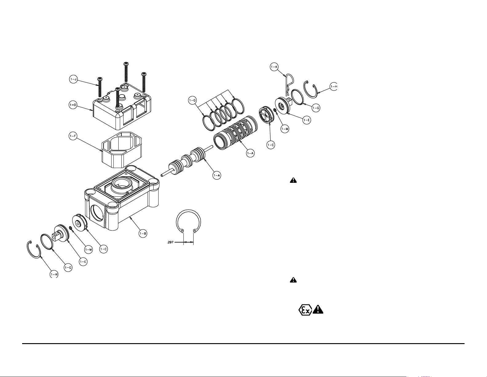
Air Valve with Stroke Indicator Assembly Drawing & Parts List
I M2 c T5
II 2GD T5
NOTE: CHECK GAP AFTER ASSEMBLY
TO INSURE COMPLETE
INSTALLATION OF RETAINING RING
AIR VALVE ASSEMBLY PARTS LIST
Item Part Number Description Qty
1 031-146-000 Air Valve Assembly 1
1-A 031-143-000 Sleeve and Spool Set 1
1-B 095-094-559 Body, Air Valve 1
1-C 132-029-552 Bumper 2
1-D 165-096-559 Cap, Mufer 1
1-E 165-098-147 Cap, End 2
1-F 530-028-550 Mufer 1
1-G 560-020-360 O-Ring 8
1-H 675-044-115 Ring, Retaining 2
1-J 710-015-115 Screw, Self Tapping 4
1-K 210-008-330 Clip, Safety 1
1-M 560-029-360 O-Ring 2
For Pumps with Alternate Mesh, Sound Dampening Mufers
or Piped Exhaust:
1 031-147-000 Air Valve Assembly 1
(includes all items on 031-146-000 minus 1-D, 1-F, & 1-J).
ATEX Compliant
m15mdl1sm-rev0713 Model M15 Metallic Page 17
Page 20
AIR DISTRIBUTION VALVE WITH
STROKE INDICATOR OPTION
SERVICING
To service the air valve rst shut
off the compressed air supply, bleed
the pressure from the pump, and
disconnect the air supply line from the
pump.
Step #1: See COMPOSITE REPAIR
PARTS DRAWING.
Using a 5/16" Allen wrench, remove
the four hex socket capscrews (item 12)
and four at washers (item 36). Remove
the air valve assembly from the pump.
Remove and inspect gasket (item
18) for cracks or damage. Replace
gasket if needed.
Step #2: Disassembly of the air
valve.
To access the internal air valve
components first remove the two
retaining rings (item 1-H) from each
end of the air valve assembly using clip
ring pliers.
Next remove the two end caps (item
1-E). Inspect the o-ring (items 1-G)
and 1-M) for cuts or wear. Replace the
o-rings if necessary.
Remove the two bumpers (item
1-C). Inspect the bumpers for cut, wear
or abrasion. Replace if necessary.
Remove the spool (part of item
1-A) from the sleeve. Be careful not to
scratch or damage the outer diameter
of the spool. Wipe spool with a soft cloth
and inspect for scratches or wear.
Inspect the inner diameter of the
sleeve (part of item 1-A) for dirt,
scratches, or other contaminants.
Remove the sleeve if needed and replace
with a new sleeve and spool set (item
1-A).
Step #3: Reassembly of the air valve.
Install one bumper (item 1-C) and
one end cap (item 1-E) with o-rings
(item 1-G and 1-M) into one end of the
air valve body (item 1-B). Install one
retaining ring (item 1-H), into the groove
on the same end. Insert the safety
clip (item 1-K) through the smaller
unthreaded hole in the endcap.
Remove the new sleeve and spool
set (item 1-A) from the plastic bag.
Carefully remove the spool from the
sleeve. Install the six o-rings (item 1-G)
into the six grooves on the sleeve. Apply
a light coating of grease to the o-rings
before installing the sleeve into the
valve body (item 1-B). Align the slots
in the sleeve with the slots in the valve
body. Insert the spool into the sleeve.
Be careful not to scratch or damage the
spool during installation. Push the spool
in until the pin touches the safety clip
on the opposite end.
Install the remaining bumper, end
cap with o-rings and retaining ring.
Fasten the air valve assembly
(item 1) and gasket (item 18) to the
pump.
Connect the compressed air line to
the pump. Remove the safety clip. The
pump is now ready for operation.
IMPORTANT
Read these instructions
completely, before
installation and
start-up. It is the
responsibility of the
purchaser to retain this
manual for reference. Failure to comply
with the recommendations stated in this
manual will damage the pump, and void
factory warranty.
m15mdl1sm-rev0713 Model M15 Metallic Page 18
Page 21
40
38
39
38
42
41
Solenoid Shifted Air Valve Drawing
II 2G EEx m c T5
II 2D c IP65 T100°C
SOLENOID SHIFTED AIR VALVE PARTS LIST
(Includes all items used on Composite Repair Parts List except as shown)
Item Part Number Description Qty
38 893-097-000 Solenoid Valve, NEMA4 1
39 219-001-000 Solenoid Coil, 24VDC 1
219-004-000 Solenoid Coil, 24VAC/12VDC 1
219-002-000 Solenoid Coil, 120VAC 1
219-003-000 Solenoid Coil, 240VAC 1
40 241-001-000 Connector, conduit 1
241-003-000 Conduit Connector with 1
Suppression Diode (DC Only)
41 170-029-330 Capscrew, Hex HD 5/16-18 x 1.50 4
42 618-051-150 Plug 2
IEC EEX m T4
For Explosion Proof Solenoid Coils used in North America and
outside the European Union.
39 219-009-001 Solenoid Coil, 120VAC 60 Hz 1
219-009-002 Solenoid Coil, 240VAC 60 Hz 1
219-009-003 Solenoid Coil, 12VDC 1
219-009-004 Solenoid Coil, 24VDC 1
219-009-005 Solenoid Coil, 110VAC 50 Hz 1
219-009-006 Solenoid Coil, 230VAC 50 Hz 1
Note: Item 40 (Conduit Connector) is not required
For ATEX Compliant Solenoid Coils used in the European Union
*
39 219-011-001 Solenoid Coil, Single mounting 12 VDC, 3.3W / 267mA 1
219-011-002 Solenoid Coil, Single mounting 24 VDC, 3.3W / 136mA 1
219-011-003 Solenoid Coil, Single mounting 110/120 VAC, 3.4W / 29mA 1
219-011-004 Solenoid Coil, Single mounting 220/240 VAC, 3.4W / 15mA 1
Note: Item 35 (Conduit Connector) is not required
Compressed Air Temperature Range: Maximum Ambient Temperature to plus 50°C
II 2G EEx m c II T5
II 3/2 G Ex m c II T5
II 2D c IP65 T100°c
*Special Conditions For Safe Use
A fuse corresponding to its rated current (max. 3*I
series to each solenoid as short circuit protection. For very low rated currents of the solenoid the fuse of lowest current value according to the indicated IEC standard will be sufcient. The fuse may be
accommodated in the associated supply unit or shall be separately arranged. The rated voltage to the fuse shall be equal to or greater than the stated rated voltage of the magnet coil. The breakage
capacity of the fuse-link shall be as high as or higher than the maximum expected short circuit current at the location of the installation (usually 1500 A). A maximum permissible ripple of 20% is valid for
all magnets of direct-current design.
m15mdl1sm-rev0713 Model M15 Metallic Page 19
according IEC 60127-2-1) or a motor protecting switch with short-circuit and thermal instantaneous tripping (set to rated current) shall be connected in
rat
Page 22
SOLENOID SHIFTED AIR
DISTRIBUTION VALVE OPTION
MARATHON’s solenoid shifted,
air distribution valve option utilizes
electrical signals to precisely control
your MARATHON’s speed. The solenoid
coil is connected to the MARATHON
Solenoid Rate Controller/Batch Control,
or a customer - supplied control.
Compressed air provides the pumping
power, while electrical signals control
pump speed (pumping rate).
OPERATION
The Solenoid Shifted MARATHON has a
solenoid operated, air distribution valve
in place of the standard MARATHON’s
pilot operated, air distribution valve.
Where a pilot valve is normally utilized
to cycle the pump’s air distribution
valve, an electric solenoid is utilized.
As the solenoid is powered, one of the
pump’s air chambers is pressurized
while the other chamber is exhausted.
When electric power is turned off, the
solenoid shifts and the pressurized
chamber is exhausted while the other
chamber is pressurized. By alternately
applying and removing power to the
solenoid, the pump cycles much like a
standard MARATHON pump, with one
exception. This option provides a way
to precisely control and monitor pump
speed.
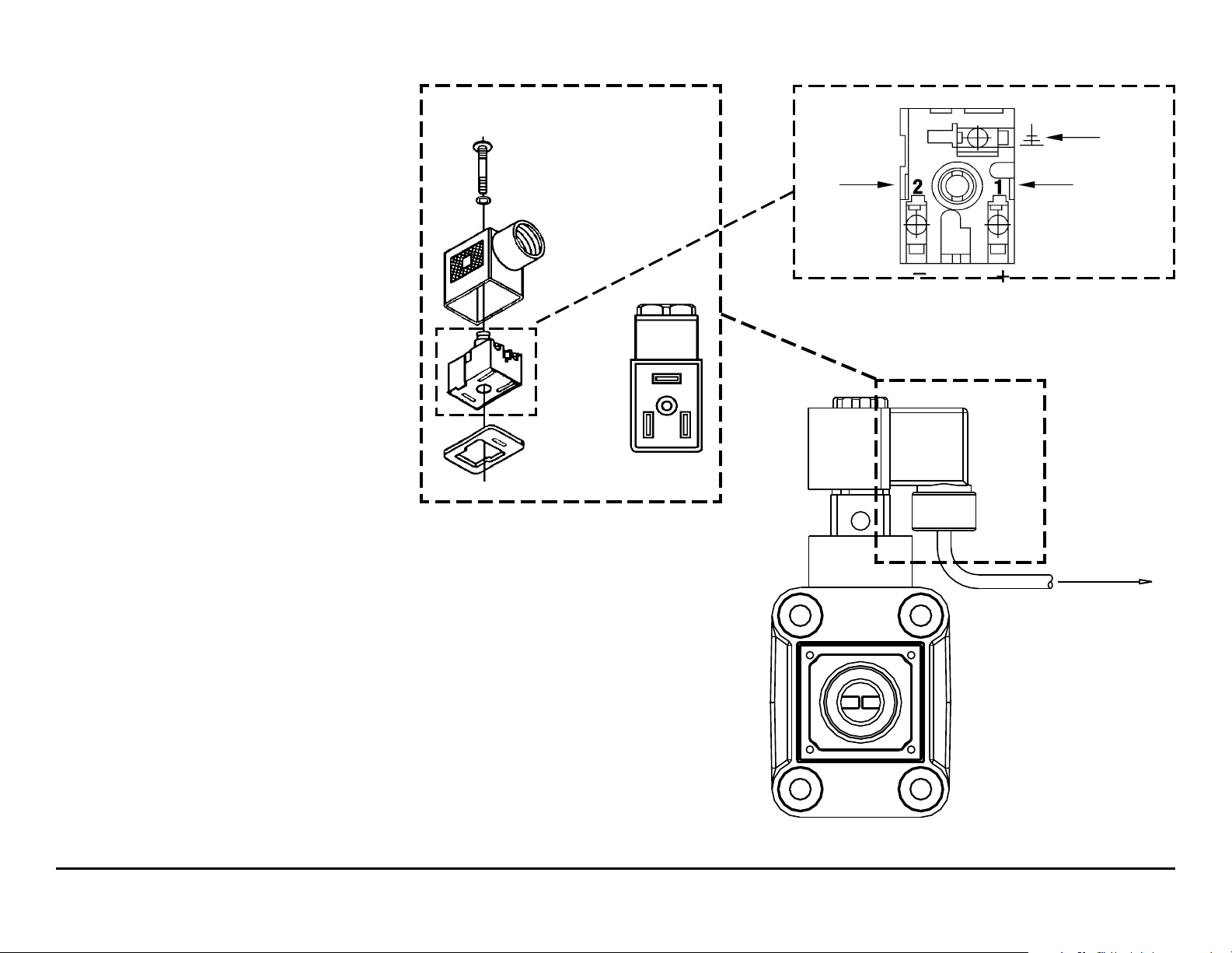
Solenoid Connector
Before wiring, remove
terminal block from
conduit connector.
Wiring
Diagram
#2 Terminal Neutral
(Negative)
3rd Terminal for
ground.
#1 Terminal
Power
(Positive)
BEFORE INSTALLATION
Before wiring the solenoid, make
certain it is compatible with your system
voltage.
m15mdl1sm-rev0713 Model M15 Metallic Page 20
Page 23
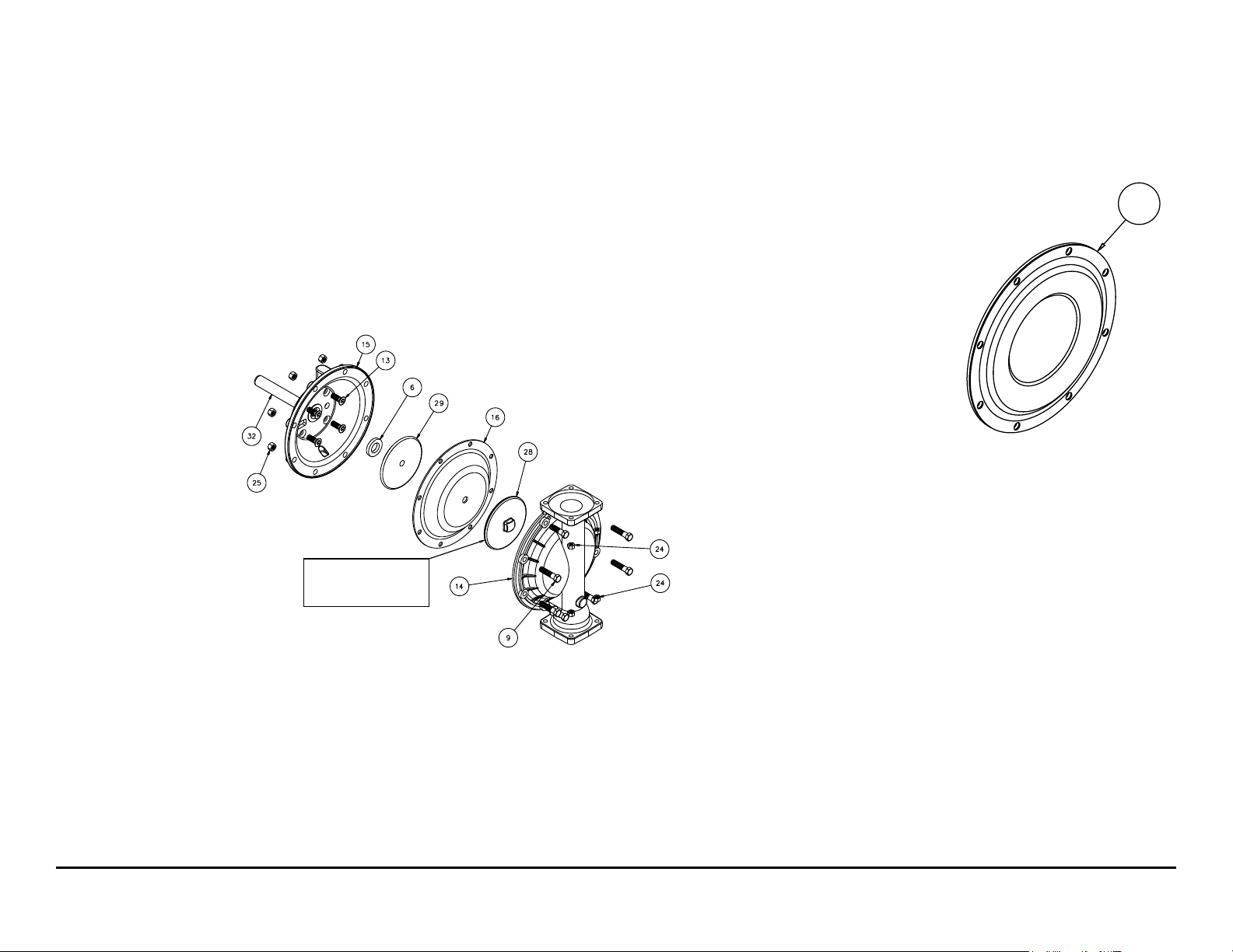
Diaphragm Service Drawing,
Torque: Plate to Plate
480 in. lbs.
600 in. lbs. Santoprene
Diaphragm Service Drawing,
One-Piece Bonded
with Overlay
Non-Overlay
*
Diaphragm Service
Drawing
17
*AVAILABLE FOR FIELD CONVERSION FROM OVERLAY
TO ONE-PIECE BONDED DIAPHRAGM KITS:
Kit: 475-254-000
2 286-113-000 One-Piece Diaphragm
2 612-217-150 Inner Plates
m15mdl1sm-rev0713 Model M15 Metallic Page 21
Page 24

DIAPHRAGM SERVICING
To service the diaphragms rst shut
off the suction, then shut off the
discharge lines to the pump. Shut off
the compressed air supply, bleed the
pressure from the pump and disconnect
the air supply line from the pump. Drain
any remaining liquid from the pump.
Step #1: See the pump assembly
drawing and the diaphragm servicing
illustration.
Using a 1/2” wrench or socket,
remove the 16 capscrews (item 9) that
fasten the manifolds (items 22 & 23) to
the outer chambers (item 14).
Step #2: Removing outer chambers.
Using a 1/2” wrench or socket,
remove the 16 capscrews (item 9), that
fasten the outer chambers (item 13),
diaphragms (item 14) and intermediate
(item 5) together.
Step #3: Removing the diaphragms
and diaphragm plates.
Use a 7/8” wrench or six point
socket to remove the outer diaphragm
plate assemblies, diaphragms (item 16)
and inner diaphragm plates (item 29)
from the diaphragm rod (item 32) by
turning counterclockwise. Inspect
the diaphragm for cuts, punctures,
abrasive wear or chemical attack.
Replace the diaphragms if necessary.
DO NOT USE A WRENCH ON THE
DIAPHRAGM ROD. FLAWS ON THE
SURFACE MAY DAMAGE BEARINGS
AND SEALS.
Step #4: Assembling the diaphragm
and diaphragm plates to the diaphragm
rod.
Push the threaded stud of one outer
diaphragm plate assembly through the
center of one diaphragm and through
one inner diaphragm plate. Install the
diaphragm with the natural bulge facing
away from the diaphragm rod and make
sure the radius on the inner diaphragm
plate is towards the diaphragm, as
indicated on the diaphragm servicing
illustration. Thread the assembly onto
the diaphragm rod, leaving loose.
Step #5: Installing the diaphragm and
rod assembly to the pump.
Make sure the bumper (item 6) is
installed over the diaphragm rod. Insert
rod into pump.
On the opposite side of the pump,
pull the diaphragm rod out as far as
possible. Make sure the second bumper is installed over the diaphragm rod.
Push the threaded stud of the other
outer diaphragm plate assembly through
the center of the other diaphragm and
through the other inner diaphragm
plate. Make sure the radius on the inner
diaphragm plate is towards the
diaphragm. Thread the assembly onto
the diaphragm rod. Use a 7/8” wrench
or socket to hold one outer diaphragm
plate. Then, use a torque wrench to
tighten the other outer diaphragm plate
to the diaphragm rod to 500 in. lbs.
(56.5 Newton meters).
Align one diaphragm with the
intermediate and install the outer
chamber to the pump using the 8
capscrews. Tighten the opposite
diaphragm plate until the holes in the
diaphragm align with the holes in the
intermediate. Then, install the other
outer chamber using the 8 capscrews.
Step #6: Reinstall the manifolds to the
pump using the 16 capscrews.
The pump is now ready to be
reinstalled, connected and returned to
operation.
OVERLAY DIAPHRAGM SERVICING
The overlay diaphragm (item 17)
is designed to t over the exterior of the
standard diaphragm (item 16).
Follow the same procedures
described for the standard diaphragm
for removal and installation, except tighten the outer diaphragm plate assembly,
diaphragms and inner diaphragm plate
to the diaphragm rod to 500 in. lbs.
(56.5 Newton meters).
One-Piece Bonded DIAPHRAGM
SERVICING (Bonded PTFE with
integral plate)
The one-piece bonded diaphragm
(item 17) has a threaded stud installed
in the integral plate at the factory. The
inner diaphragm plate has a through
hole instead of a threaded hole.
Place the inner plate over the
IMPORTANT
Read these instructions
completely, before
installation and
start-up. It is the
responsibility of the
purchaser to retain
this manual for reference. Failure to
comply with the recommendations
stated in this manual will damage the
pump, and void factory warranty.
diaphragm stud and thread the rst
diaphragm / inner plate onto the diaphragm rod only until the inner plate
contacts the rod. Do not tighten. A small
amount of grease may be applied between
the inner plate and the diaphragm to
facilitate assembly.
Insert the diaphragm / rod assembly into the pump and install the
outer chamber. Turn the pump over
and thread the second diaphragm /
inner plate onto the diaphragm rod.
Turn the diaphragm until the inner
plate contacts the rod and hand tighten
the assembly. Continue tightening
until the bolt holes align with the inner
chamber holes. DO NOT LEAVE THE
ASSEMBLY LOOSE.
m15mdl1sm-rev0713 Model M15 Metallic Page 22
Page 25
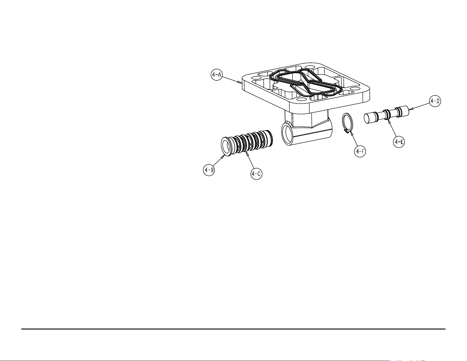
Pilot Valve Servicing, Assembly Drawing & Parts List
PILOT VALVE ASSEMBLY PARTS LIST
ITEM PART NUMBER DESCRIPTION QTY
4 095-110-000 Pilot Valve Assembly 1
4-A 095-095-157 Valve Body 1
4-B 755-052-000 Sleeve (With O-rings) 1
4-C 560-033-379 O-ring (Sleeve) 6
4-D 775-055-000 Spool (With O-rings) 1
4-E 560-023-379 O-ring (Spool) 3
4-F 675-037-080 Retaining Ring 1
FOR PUMPS WITH CAST IRON CENTER SECTION
ITEM PART NUMBER DESCRIPTION QTY
4 095-110-558 Pilot Valve Assembly 1
4-A 095-095-558 Valve Body 1
(includes all other items used on 095-110-000)
FOR PUMPS WITH STAINLESS STEEL CENTER SECTION
ITEM PART NUMBER DESCRIPTION QTY
4 095-110-110 Pilot Valve Assembly 1
4-A 095-095-110 Valve Body 1
(includes all other items used on 095-110-000)
PILOT VALVE SERVICING
To service the pilot valve rst shut
off the compressed air supply, bleed
the pressure from the pump, and
disconnect the air supply line from the
pump.
STEP #1: See pump assembly
drawing.
Using a 1/2" wrench or socket,
remove the four capscrews (item 11).
Remove the air inlet cap (item 8) and
air inlet gasket (item 20). The pilot valve
assembly (item 4) can now be removed
STEP #2: Disassembly of the
pilot valve.
Remove the pilot valve spool (item
4-D). Wipe clean and inspect spool and
o-rings for dirt, cuts or wear. Replace
the o-rings and spool if necessary.
Remove the retaining ring (item
4-F) from the end of the sleeve (item
4-B) and remove the sleeve from the
valve body (item 4-A). Wipe clean and
inspect sleeve and o-rings for dirt, cuts
or wear. Replace the o-rings and sleeve
if necessary.
STEP #3: Re-assembly of the
pilot valve.
Generously lubricate outside
diameter of the sleeve and o-rings.
Then carefully insert sleeve into valve
body. Take CAUTION when inserting
sleeve, not to shear any o-rings. Install
retaining ring to sleeve. Generously
lubricate outside diameter of spool and
o-rings. Then carefully insert spool into
sleeve. Take CAUTION when inserting
spool, not to shear any o-rings. Use
BP-LS-EP-2 multipurpose grease, or
equivalent.
STEP #4: Re-install the pilot valve
assembly into the intermediate.
Be careful to align the ends of the
pilot valve stem between the plunger
pins when inserting the pilot valve into
the cavity of the intermediate.
Re-install the gasket, air inlet cap
and capscrews. Connect the air supply
to the pump. The pump is now ready
for operation.
for inspection and service.
m15mdl1sm-rev0713 Model M15 Metallic Page 23
Page 26

ACTUATOR PLUNGER SERVICING
33
30
5
31
7
26
To service the actuator plunger rst
shut off the compressed air supply,
bleed the pressure from the pump, and
disconnect the air supply line from
the pump.
Step #1: See PUMP ASSEMBLY
DRAWING.
Using a 1/2" wrench or socket,
remove the four capscrews (items
11). Remove the air inlet cap (item
8) and air inlet gasket (item 18). The
pilot valve assembly (item 4) can now
be removed.
Step #2: Inspect the actuator
plungers.
See ILLUSTRATION AT RIGHT.
The actuator plungers (items 30)
can be reached through the pilot valve
cavity in the intermediate assembly
(item 5).
Remove the plungers (item 30) from
the bushings (item 7) in each end of the
cavity. Inspect the installed o-ring (items
26) for cuts and/or wear. Replace the
o-rings if necessary. Apply a light
coating of grease to each o-ring and
re-install the plungers in to the
bushings. Push the plungers in as far as
they will go.
To remove the bushings (item 7),
rst remove the retaining rings (item 31)
by using a at screwdriver. NOTE: It is
recommended that new retaining rings
be installed.
Step #3: Re-install the pilot valve
assembly into the intermediate assembly.
Be careful to align the ends of
the stem between the plungers when
inserting the stem of the pilot valve into
the cavity of the intermediate.
Re-install the gasket (item 18),
air inlet cap (item 8) and capscrews
(item 11).
Connect the air supply to the pump.
The pump is now ready for operation.
ACTUATOR PLUNGER DRAWING
IMPORTANT
Read these instructions
completely, before
installation and
start-up. It is the
responsibility of the
purchaser to retain this
manual for reference. Failure to comply
with the recommendations stated in this
manual will damage the pump, and void
factory warranty.
m15mdl1sm-rev0713 Model M15 Metallic Page 24
Page 27

CHECK VALVE SERVICING
Before servicing the check valve
components, rst shut off the suction
line and then the discharge line to the
pump. Next, shut off the compressed
air supply, bleed air pressure from the
pump, and disconnect the air supply
line from the pump. Drain any remaining
uid from the pump. The pump can now
be removed for service.
To access the check valve
components, remove the manifold
(item 23 or item 22 not shown). Use a
1/2" wrench or socket to remove
the fasteners. Once the manifold is
removed, the check valve components
can be seen.
Inspect the check balls (items 2) for
wear, abrasion, or cuts on the spherical
surface. The check valve seats (item
34) should be inspected for cuts,
abrasive wear, or embedded material
on the surfaces of both the external
and internal chambers. The spherical
surface of the check balls must seat
ush to the surface of the check valve
seats for the pump to operate to
peak efciency. Replace any worn or
damaged parts as necessary.
Re-assemble the check valve
components. The seat should t into
the counter bore of the outer chamber.
The pump can now be reassembled,
reconnected and returned to operation.
METALLIC SEATS
Two o-rings (or conductive PTFE
seals) (item 27) are required for metallic
seats.
Check Valve Drawing
with Metallic Seats
with Non-Metallic
Seats
m15mdl1sm-rev0713 Model M15 Metallic Page 25
Page 28

Optional Mufer Congurations, Drawing
I M2 c T5
II 2GD T5
OPTION 0
530-028-550 Integral Mufer uses (1) Cap
and (4) 710-015-115 Self Tapping Screw to
hold it in place.
OPTION 1
530-027-000 Sound Dampening Mufer
screws directly into the Air Valve body.
This mufer is equipped with a porous
plastic element.
OPTION 2
530-010-000 Mesh Mufer screws
directly into the Air Valve Body. This
mufer is equipped with a metal element.
OPTION 6
530-033-000 Metal Mufer screws
directly into the Air Body.
*
*
Note: Cannot be used with Air Valve
Assembly 031-179-000 used on
models equipped with cast iron or
stainless steel centers.
ATEX Compliant
Option 0
Option 6
m15mdl1sm-rev0713 Model M15 Metallic Page 26
Option 1 and 2
Page 29

PUMPING HAZARDOUS LIQUIDS
1
When a diaphragm fails, the pumped
liquid or fumes enter the air end of the
pump. Fumes are exhausted into
the surrounding environment. When
pumping hazardous or toxic materials,
the exhaust air must be piped to an
appropriate area for safe disposal. See
illustration #1 at right.
This pump can be submerged if
the pump materials of construction
are compatible with the liquid being
pumped. The air exhaust must be
piped above the liquid level. See
illustration #2 at right. Piping used for
the air exhaust must not be smaller
than 1" (2.54 cm) diameter. Reducing
the pipe size will restrict air ow and
reduce pump performance. When the
pumped product source is at a higher
level than the pump (ooded suction
condition), pipe the exhaust higher than
the product source to prevent siphoning
spills. See illustration #3 at right.
CONVERTING THE PUMP FOR
PIPING THE EXHAUST AIR
The following steps are necessary
to convert the pump to pipe the exhaust
air away from the pump.
Remove the mufer (item 43). The
air distribution valve (item 1) has 1" NPT
threads for piped exhaust.
IMPORTANT INSTALLATION
NOTE: The manufacturer recommends
installing a exible conductive hose
or connection between the pump
and any rigid plumbing. This reduces
stresses on the molded threads of the
air exhaust port. Failure to do so may
result in damage to the air distribution
valve body.
Any piping or hose connected to
the pump’s air exhaust port must be
conductive and physically supported.
Failure to support these connections
could also result in damage to the air
distribution valve body.
Air Valve
Assembly
43
On ATEX compliant units the
pump comes equipped with
a standard metal mufer
CONVERTED EXHAUST ILLUSTRATION
PUMP INSTALLATION AREA
1" DIAMETER AIR
EXHAUST PIPING
Illustration #1
LIQUID
LEVEL
SUCTION
LINE
Illustration #2
LIQUID
LEVEL
SAFE AIR
EXHAUST
DISPOSAL
AREA
MUFFLER
MUFFLER
1" DIAMETER AIR
EXHAUST PIPING
MUFFLER
1" DIAMETER AIR
EXHAUST PIPING
SUCTION
LINE
Illustration #3
m15mdl1sm-rev0713 Model M15 Metallic Page 27
Page 30

Pulse Output Kit Drawing
PULSE OUTPUT KIT OPTION
This pump can be tted with a Pulse Output Kit. This converts the mechanical
strokes of the pump to an electrical signal which interfaces with the Stroke Counter/
Batch Controller or user control devices such as a PLC.
The Pulse Output Kits mount directly onto the Mufer Cap on the Air Distribution
Valve Assembly or onto the air valve and senses each stroke of the main spool.
Consult the factory for further information and availability.
Pulse Output Kits
475-244-001 10-30 VDC
475-244-002 110/220 VAC
475-244-003 10-30VDC, 110VAC and 220 VAC
m15mdl1sm-rev0713 Model M15 Metallic Page 28
Page 31

Grounding The Pump
To be fully groundable, the pumps must be ATEX
Compliant. Refer to pump data sheet for ordering.
One eyelet is fastened to the pump hardware.
One eyelet is installed to a true earth ground.
(Requires a maximum 5/16 or 8mm diameter bolt)
This 8 foot long (244 centimeters) Ground Strap,
part number 920-025-000, can be ordered as a
service part.
To reduce the risk of static electrical sparking,
this pump must be grounded. Check the local
electrical code for detailed grounding instruction
and the type of equipment required.
WARNING
Take action to prevent static
sparking. Fire or explosion can
result, especially when handling
flammable liquids. The pump,
piping, valves, containers or other
miscellaneous equipment must
be grounded.
m15mdl1sm-rev0713 Model M15 Metallic Page 29
Page 32

Declaration of Conformity
Manufacturer: Warren Rupp, Inc.®, 800 N. Main Street, P.O. Box 1568,
Mansfield, Ohio, 44901-1568 USA
certifies that Air-Operated Double Diaphragm Pump Series:
M Non-Metallic, M Metallic, and Surge Suppressors comply
with the European Community Directive 2006/42/EC on Machinery,
according to Annex VIII. This product has used Harmonized Standard
EN809:1998+A1:2009, Pumps and Pump Units for Liquids - Common Safety
Requirements, to verify conformance.
October 20, 2005
Signature of authorized person
Date of issue
David Roseberry
Printed name of authorized person
Revision Level: F
Engineering Manager
Title
August 23, 2012
Date of revision
Page 33

EC Declaration of Conformity
In accordance with ATEX Directive 94/9/EC,
Equipment intended for use in potentially explosive environments.
Manufacturer: Warren Rupp, Inc.
800 North Main Street, P.O. Box 1568, Mansfield, OH 44901-1568 USA
EN 60079-25: 2004
For pumps equipped with Pulse Output ATEX Option
KEMA Quality B.V. (0344)
AODD Pumps and Surge Suppressors
For Type Examination Designations, see page 2 (back)
AODD (Air-Operated Double Diaphragm) Pumps
EC Type Examination Certificate No. Pumps: KEMA 09ATEX0071 X
KEMA Quality B.V.
Utrechtseweg 310
6812 AR Arnhem, The Netherlands
DATE/APPROVAL/TITLE:
27 MAY 2010
®
, A Unit of IDEX Corportion
Applicable Standard:
EN13463-1: 2001,
EN13463-5: 2003
David Roseberry, Engineering Manager
Page 34
EC Declaration of Conformity
ATEX Summary of Markings
Type Marking Listed In
Pump types, M05, M1F, M15,
M20 and M30 provided with the
pulse output option
Pump types, M05, M1F, M15
M20 and M30 provided with the
integral solenoid option
Pump types, MPB1/4, M05,
M1F, M15, M20, M30, MSB1,
MHDF1, MHDF2 without the
above listed options, no
aluminum parts
Pump types,
MPB1/4, M05, M1F, M15,
M20, M30, MSB1, MHDF1,
MHDF2, MHDF3
MT Series Surge Suppressors II 2 G T5
EC Type Certificate No. Pumps: KEMA 09ATEX0071 X
Type Certificate No. Pumps: KEMA 09ATEX0072 X
Type Certificate No. Suppressors: KEMA 09ATEX0073
II 2 G Ex ia c IIC T5
II 3/2 G Ex ia c IIC T5
II 2 D
Ex c iaD 20 IP67 T100oC
II 2 G EEx m c II T5
II 3/2 G EEx m c II T5
II 2 D c IP65 T100
II 1 G c T5
II 3/1 G c T5
II 1 D c T100
I M1 c
I M2 c
II 2 G c T5
II 3/2 G c T5
II 2 D c T100
II 3/2 G T5
II 2 D T100
Non-Conductive
Fluids
KEMA 09ATEX0071 X
CE 0344
KEMA 09ATEX0071 X
o
C
o
C
o
C
o
C
CE 0344
KEMA 09ATEX0071 X
KEMA 09ATEX0072 X
CE 0344
KEMA 09ATEX0072 X
CE
KEMA 09ATEX0073
CE
KEMA 09ATEX0071 X
KEMA 09ATEX0071 X
KEMA 09ATEX0071 X
KEMA 09ATEX0071 X
KEMA 09ATEX0071 X
KEMA 09ATEX0071 X
KEMA 09ATEX0071 X
KEMA 09ATEX0071 X
KEMA 09ATEX0071 X
KEMA 09ATEX0071 X
KEMA 09ATEX0072 X
KEMA 09ATEX0072 X
KEMA 09ATEX0072 X
KEMA 09ATEX0072 X
KEMA 09ATEX0073
KEMA 09ATEX0073
KEMA 09ATEX0073
No
Yes
Yes
No
Yes
Yes
No
Yes
Yes
No
Yes
No
Yes
Yes
No
Yes
Yes
 Loading...