

Page 1
Samsung Electronics 2-1
2. Reference Information
2-1 Servicing Jigs and Special Tools
1. For this VCR chassis, the program switch and the
sensors (start/end/reel) are located on the main
PCB, not on the deck assÕy.
2. As long as the deck assÕy is connected to the main
PCB, all repairs are possible.
Important : In order to repair the main PCB
without the deck assÕy connected, the X-5 chassis
jig should be used.
3. To emulate the function of the sensors, connect a
jumper or solder land (two point) at service
option(W750) on the function-timer PCB.
4. The X-5 chassis jig can be used for the following :
1) When repairing or confirming the operation of the
deck assÕy.
2) When replacing or repairing the components
located under the deck assÕy.
3) When repairing the function PCB.
5. The X-5 chassis jig can not be used for the
following :
1) Repairing defects in the video section.
2) Repairing defects in the audio section.
3) If the defect is related to tape speed.
Note :
1) Repair may not be possible if there is external
noise between the deck assÕy and main PCB.
2) If tape control signal is not connected to the jig,
the VCR must be operated in SP mode.
2-1-1 Servicing guide
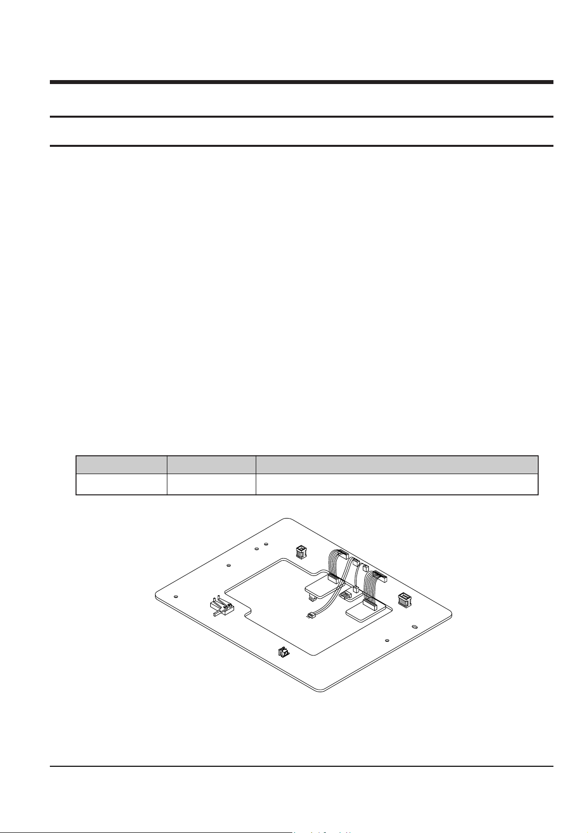
X-5 Chassis Jig
Jig Item
68140-500-013
Part No.
Connects the deck ass’y to the main PCB connecting cable.
Use
2-1-2 Servicing Jig
Page 2
Reference Information
2-2 Samsung Electronics
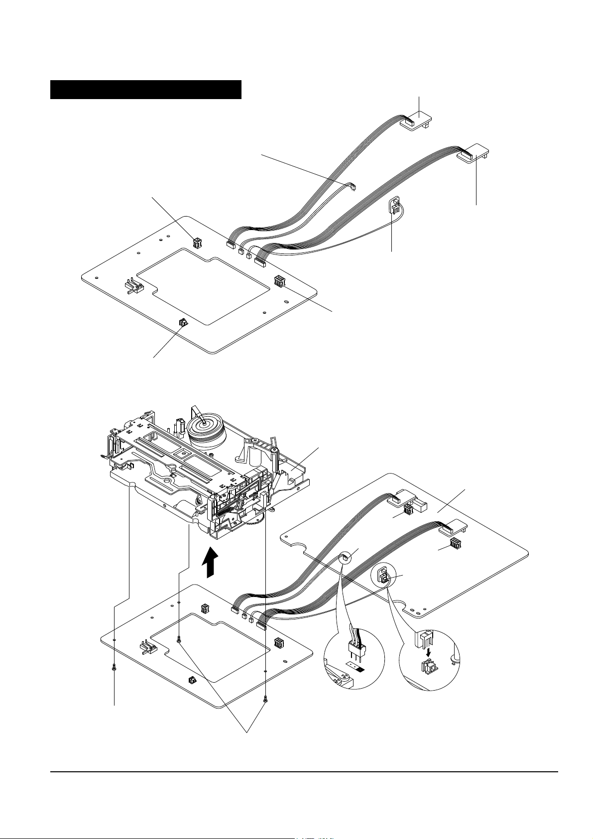
2-1-4 How to Connect X-5 chassis jig
4. Insert wafers of drum motor, capstan motor and
loading motor on X-5 chassis jig into each of the
connectors of deck assÕy, and then secure with
three screws.
5. Solder the 3 leads of the jig cable to ÒCN605Ó
on the main PCB.
6. Apply power to the function PCB.
7. Insert a test tape into the housing assÕy.
8. Simultaneously touch the start and end sensor
LEDs on the PCB, so that the tape loads
automatically. After the tape is loaded, all of the
function buttons on the function PCB can be
used.
9. If the test tape is ejected while the jig is in use,
attempt to re-load the tape by simultaneously
touching the start and end sensor LEDs. If the tape
still does not load, reset the function PCB by
pressing SW715.
Note : After completing repairs, SW715 on the function PCB in order to reset.
1. Unplug the power cord from AC outlet.
2. Remove the deck assÕy from main PCB (See Page
4-5 of service manual).
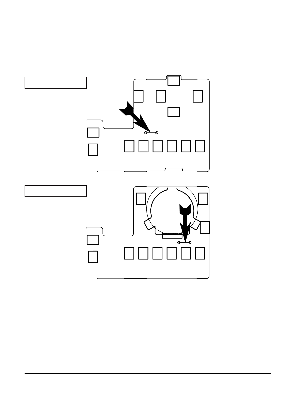
3. To emulate the function of the sensors, place a
jumper or solder land (two point) at service
option(W750) on the function-timer PCB.
(see diagram below).
SW712
PLAY
SW709
STOP
SW703
P/S
SW715
RESET
W750SERVICE OPTION
SW702
TV/VCR
SW708
NICAM
SW706
SP/LP
SW711
SYSTEM
SW707
REC
SW701
CH/DOWN
SW705
CH/UP
JS701
Function-Timer (Component side)
SW713
FF
SW703
P/S
SW712
PLAY
SW709
STOP
SW714
REW
W750
SERVICE OPTION
SW715
RESET
SW708
NICAM
SW702
TV/VCR
SW706
SP/LP
SW711
SYSTEM
SW707
REC
SW705
CH/UP
SW701
CH/DOWN
Function-Timer (Component side)
SV-A120G/SVR-600
SV-A140G/SVR-605
Page 3
Reference Information
Samsung Electronics 2-3
CONNECTS TO THE ASS'Y MAIN CN604.
CONNECTS TO THE ASS'Y MAIN CN605.
CONNECTS TO THE
ASS'Y MAIN CN603.
CONNECTS TO THE ASS'Y MAIN CN601.
CONNECTS TO THE DRUM MOTOR
CONNECTOR OF ASS'Y FULL DECK.
CONNECTS TO THE CAPSTAN MOTOR
CONNECTOR OF ASS'Y FULL DECK.
CONNECTS TO THE LOADING MOTOR CONNECTOR OF ASS'Y FULL DECK.
ASS'Y FULL DECK
ASS'Y MAIN
1 SCREW (1-3X10)
2 SCREWS (2-3X10)
CN604
CN603
CN605
CN601
How to Connect X-5 chassis jig
Page 4

Reference Information
2-4 Samsung Electronics
2-2 IC BLOCK
2-2-1 IC601 (HD6473977)
Page 5

Reference Information
Samsung Electronics 2-5
2-2-2 IC301 (SS11501M/SS11511M)
Page 6

Reference Information
2-6 Samsung Electronics
2-2-3 IC302 (LA7416)
Page 7

Reference Information
Samsung Electronics 2-7
2-2-4 IC303 (SS23377M/SS23378M)
Page 8

Reference Information
2-8 Samsung Electronics
2-2-5 IC501 (TA1264)
Page 9

Reference Information
Samsung Electronics 2-9
2-2-6 IC502 (LA7256)
Page 10

Reference Information
2-10 Samsung Electronics
MEMO
 Loading...