

Samsung Electronics 5-1
5. Alignment and Adjustment
5-1 Mechanical Adjustment
Reference :
For other mechanical adjustments except A/C Head position (X-point) adjustment, refer to the mechanical
manual (DX7-R/DX7-RC/DX8-R/DX8-RC, AC68-20316A).
Test point : TP05 (Envelope)
TP04 (H’D S/W -Trigger)
TP03 (CTL Pulse)
TP06 (Audio out)
Test tape : PAL Color bar
Mono scope
Blank tape (E-240)
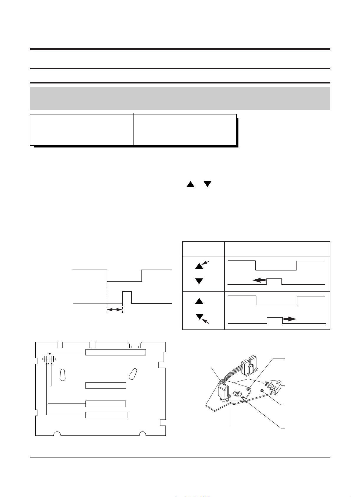
5-1-1 A/C Head Point (X-point) Adjustment
1. Playback the mono scope alignment tape.
2. Connect CH-1 scope probe to TP03 and CH-2 scope probe to TP04. And then, trigger head switching pulse.
3. Set tracking preset to 1msec using the ÒTrackingÓ button / of remote control. (Refer to Fig. 1 and 2)
4. Connect CH-1 scope probe to TP05 and the CH-2 to ÒHÕD S/WÓ trigger on CH-1.
5. Insert the adjusting driver(+) into X-point adjusting gear. Adjust the driver in either direction for maximum
envelope waveform.
Note : Since the adjusting gear unit may be damaged, do not adjust by force when adjusting the X-point using
the adjusting driver(+). After turn the X-point adjusting screw(D) counterclockwise a little, perform the
adjustment. After adjustment is completed, tighten the screw. (Refer to Fig. 3)
<Setting of scope>
- Volt/div. : CH-1 = 0.1V - Time/div. : 5msec
CH-2 = 0.2V
CH-2 Probe
TP04
H’D S/W Pulse
CH-1 Probe
TP03
CTL Pulse
1msec
Fig. 5-1 Tracking preset adjustment
TP4 : HEAD S/W-TRIGGER
TP5 : ENVELOPE
TP3 : CTL PULSE
TP6 : AUDIO OUT
Fig. 5-2 Control pulse adjustment
SCREW(C)
TILT ADJUST
X-POSITION
ADJUST GEAR
HOLE
SCREW(A)
HEIGHT ADJUST
SCREW(B)
AZIMUTH ADJUST
SCREW(D)
X-POINT LOCKING
Fig. 5-4 Location of A/C Head adjustment screw
REMOTE
BUTTONS
TRACKING
TRACKING
CONTROL PULSE REMOVE
PUSH
PUSH
Fig. 5-3 PCB Layout
Alignment and Adjustment
5-2 Samsung Electronics
Test point
5-2 Electrical Adjustment
Step Adjustment Item
1. Mode and input signal/
alignment tape
2. Test point and ADJ. part
3. Result and Remarks
ADJ. point
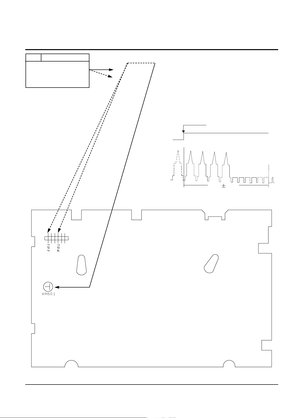
5-2-1 Head switching point
1. ÒPBÓ, Alignment tape color bars.
2. TP4 (HÕD S/W), TP7(Video out) and VR601.
3. Connect an oscilloscopeÕs CH-1 to TP4 for
triggering and CH-2 to TP7.
4. Adjust VR601 so that the head switching point is
positioned 6.5 ± 0.5H from the V-SYNC left edge
as shown.
(Main PCB - Component Side)
SWITCHING POINT
SW25HZ
PULSE
CH-2
CH-1
VIDEO OUT
6.5H
0.5H

Alignment and Adjustment
Samsung Electronics 5-3
5-3 Timing Chart of Program S/W
EJECT
CASSETTE IN
UNLOAD
R. PS
R. SLOW
STILL
PLAY
STOP
FF/REW
POSITION
PROGRAM S/W (SW601)
E/S S/S SW A SW B
ACTION MODE
L
H
-
-
-
-
-
-
-
L
L H
-
-
-
-
-
-
-
L
L
L
L H
H
H L
L H
H
H L
L
L
L H
H
H L
L
L
L H
H
EJECT
CASSETTE IN
UNLOAD
R. PS, Z-R. PS
PINCH ROLLER OFF POSITION
STILL
PB, T-STOP, REC, PAUSE, F. PS, Z-FPS
STOP, POWER OFF
FF, REW
SW A
(IC601-16)
SW B
(IC601-17)
END
-SENSOR
(IC601-38)
START
-SENSOR
(IC601-6)
EJECT UNLOAD RPS R.SLW STILL PB STOP F/R
CASS IN

Alignment and Adjustment
5-4 Samsung Electronics
MEMO
 Loading...