

Samsung SVR-171 Precautions
Samsung Electronics
2-1
2. Alignment and Adjustments
2-1 VCR Adjustment
1) X-Point (Tracking center) adjustment, “Head switching adjustment” and “NVRAM option setting” can be adjusted with remote control.
2) When replacing the Main PCB Micom (IC601) and NVRAM (IC605 ; EEPROM) be sure to adjust the “Head switching adjustment” and
“NVRAM option setting”.
3) When replacing the cylinder ass’y, be sure to adjust the “X-Point” and “Head switching adjustment”.
4) Among Samsung VCR remote control used for adjustment as a accessory, only the remote control that has figures buttons (0 ~ 9) and
“SPEED” button are available for all adjustment regardless of chassis.
5) How to adjust.
- Momently short-circuit the test point on Main PCB with pincers to set the adjustment mode.
- If the corresponding adjustment button is pressed, the adjustment is performed automatically.
- When the adjustment is completed, be sure to turn the power off.
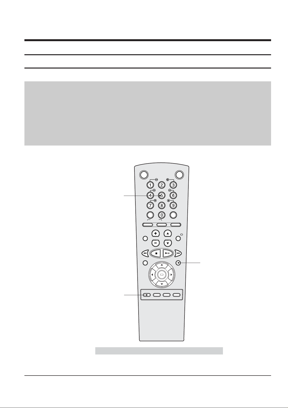
2-1-1(a) Location of adjustment button of remote control
Fig. 2-1
Remote Control for adjustment is not supplied as a Service Jig.
OK
VCR STANDBY/ON TV STANDBY/ON
SLOW
SHUTTLE
V-LOCK
CLR/RST F.ADV INDEX
TV VCR INPUT
REPEAT
VOL PROG/TRK
AUDIO
REC MENU
SPEED DUB TV/VCR TIMER
DISP./
SELECT
-/--
X-Point (Tracking Center) Adjustment
("5" Button)
Head Switching Adjustment
("SPEED" Button)
NVRAM Option Setting
("MENU" Button)
2-1-1 Reference
2-2
Alignment and Adjustments
Samsung Electronics
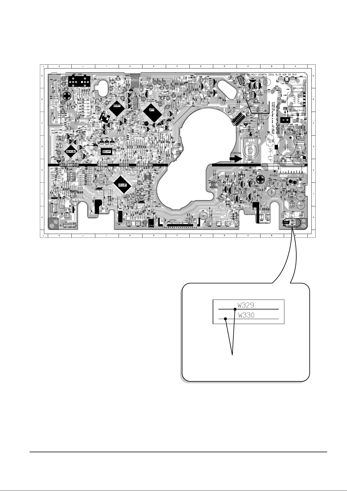
2-1-1(b) location for adjustment mode setting
Fig. 2-2 Main PCB (Top View)
Short-Circuit for few seconds and release.
(Just one time)
Alignment and Adjustments
2-3
Samsung Electronics
2-1-2 Head Switching Point Adjustment
1) Playback the alignment tape.
2) Momently short-circuit the test point on Main PCB with pincers to set the adjustment mode. (See Fig. 2-2)
3) Press the “SPEED” buttons; remote control adjustment operates automatically. (See Fig. 2-1)
4) Turn the Power off.
2-1-3 NVRAM Option Setting
1) Momently short-circuit the test point on Main PCB with pincers to set the adjustment mode. (See Fig. 2-2)
2)
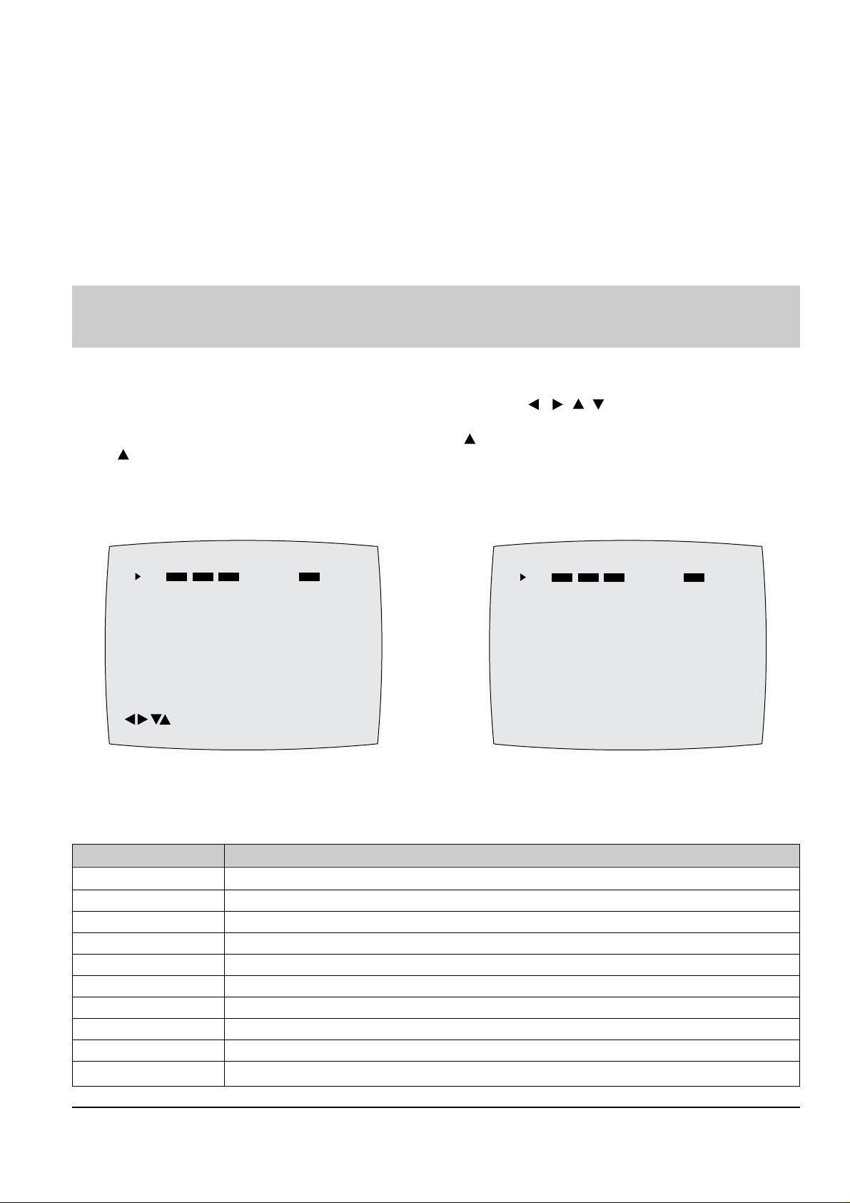
Press the “MENU” button on the remote control. The option setting appears. (See Fig. 2-3)
3)
Select the option number (See table 2-1) of corresponding model with “ , , , ” buttons on the
remote control.
4) After selecting the option number is completed, press the “ ” button of remote control.
(If “ ” button is pressed, the selected number is changescolor. ; See Fig. 2-4)
5) Press the “ENTER” button of remote control again to store the option number.
6) Turn the Power off.
1) NVRAM Option is adjusted in the factory.
2) In case Main PCB Micom (IC601) and NVRAM (IC605 ; EEPROM) are replaced, be sure to set the corresponding option number of the
required model. (If the option is not set, the unit will not operate.)
CNG : OK SAVE : RETURN
01 02 03 04 05 06 07 08
09 10 11 12 13 14 15 16
17 18 19 20 21 22 23 24
25 26 27 28 29 30 31 32
33 34 35 36 37 38 39 40
41 42 43 44 45 46 47 48
49 50 51 52 53 54 55 56
57 58 59 60 61 62 63 64
65 66 67 68 69 70 71 72
Fig. 2-3
PLEASE WAIT
01 02 03 04 05 06 07 08
09 10 11 12 13 14 15 16
17 18 19 20 21 22 23 24
25 26 27 28 29 30 31 32
33 34 35 36 37 38 39 40
41 42 43 44 45 46 47 48
49 50 51 52 53 54 55 56
57 58 59 60 61 62 63 64
65 66 67 68 69 70 71 72
Fig. 2-4
<Table 2-1 NVRAM Option Table>
MODEL OPTION NUMBERS
SVR-679 6, 7, 8, 9, 10, 12, 20, 26, 27, 32, 33, 34, 36, 38, 42, 47, 54, 57, 60, 61, 64, 65
SVR-673 6, 7, 8, 9, 10, 12, 20, 26, 27, 32, 33, 34, 36, 38, 42, 47, 54, 57, 60, 61, 64, 65
SVR-670 6, 7, 8, 9, 10, 12, 20, 26, 27, 32, 33, 34, 36, 38, 42, 47, 49, 54, 57, 60, 61, 64, 65
SVR-473 9, 10, 12, 20, 26, 27, 32, 33, 34, 36, 38, 42, 47, 54, 57, 60, 61, 64, 65
SVR-273 10, 12, 20, 26, 27, 32, 33, 34, 36, 37, 42, 47, 54, 57, 60, 61, 64, 65
SVR-2701 10, 12, 20, 26, 27, 33, 34, 36, 37, 42, 47, 54, 57, 60, 61, 64, 65
SVR-2701B 10, 12, 20, 26, 27, 33, 34, 36, 37, 42, 47, 54, 57, 60, 61, 64, 65
SVR-170 10, 12, 20, 33, 34, 35, 36, 37, 40, 47, 49, 54, 57, 60, 61, 64, 65 68, 70
SVR-171 10, 12, 20, 33, 34, 35, 36, 37, 40, 47, 54, 57, 60, 61, 64, 65 68, 70
SVR-171B 10, 12, 20, 33, 34, 35, 36, 37, 40, 47, 54, 57, 60, 61, 64, 65 68, 70
2-4
Alignment and Adjustments
Samsung Electronics
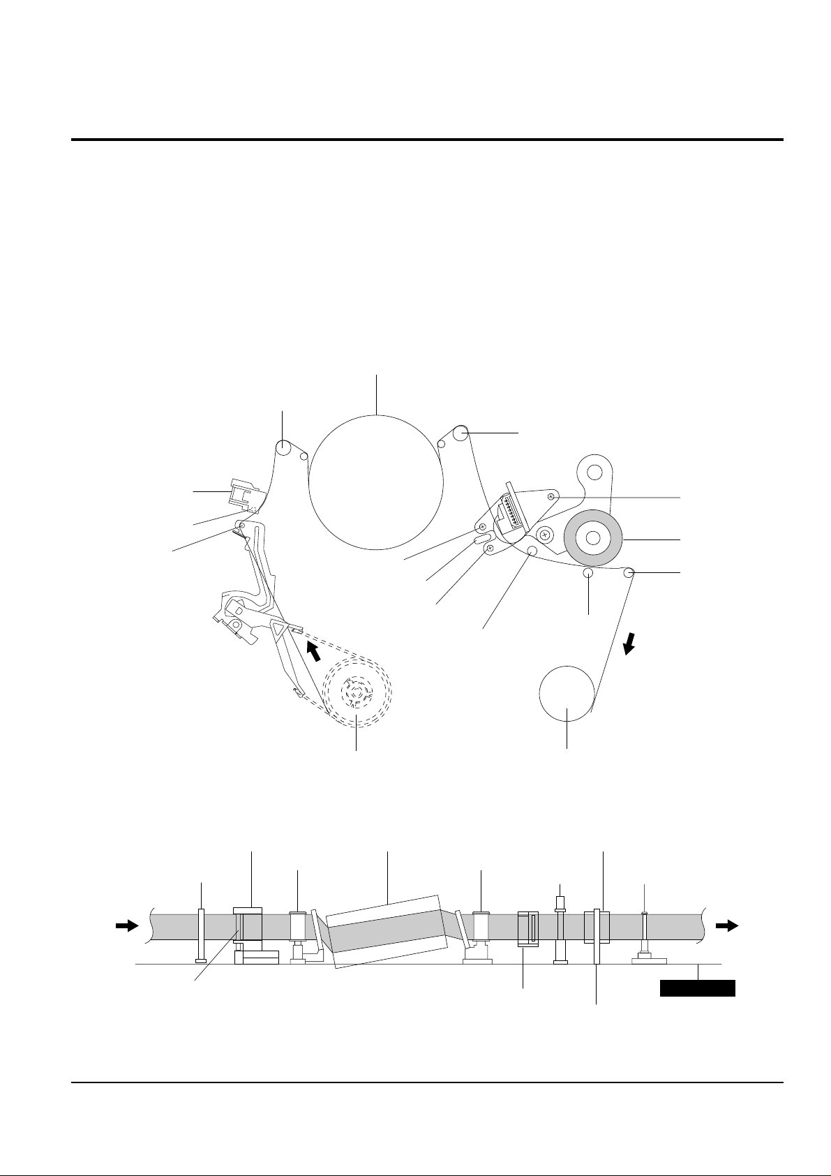
2-2 VCR Mechanical Adjustment
2-2-1 Tape Transport System and Adjustment Locations
The tape transport system has been adjusted precisely in the factory. Alignment is not necessary except for the
following :
1) Noise observed on the screen.
2) Tape damage.
3) Parts replacement in the tape transport system.
Lower flange height of tape guide is used as the reference for the transport adjustment.
To maintain the height of the tape guide and prevent damage, do not apply excessive force onto the main base.
Fig. 2-5 Location of Tape Transport Adjustment
Fig. 2-6 Tape Travel Diagram
CYLINDER ASS'Y
TAKE UP REEL DISK
#8 GUIDE POST
#9 GUIDE POST
SUPPLY REEL DISK
CAPSTAN
PINCH ROLLER
GUIDE ROLLER "T"
GUIDE ROLLER "S"
FULL ERASE HEAD
#3 GUIDE POST
TENSION POST
HEIGHT SCREW
TILT SCREW
X - POSITION
ADJUST SILT
AZIMUTH SCREW
POST TENSION
MAIN BASE
FE HEAD CYLINDER ASS'Y
PINCH ROLLER
GUIDE ROLLER "S" GUIDE ROLLER "T"
#8 GUIDE POST #9 GUIDE POST
CAPSTAN SHAFT
ACE HEAD
#3 GUIDE POST
 Loading...