

Samsung SVR-960C, SVR-945, SVR-1660C, SVR-480, SVR-1645 User Manual 2
...
Install Manual
0

Install Manual
`
Introduction
Thank you for purchasing a Samsung SVR series digital video recorder.
This manual is for SVR-3200, SVR-1680C, SVR-1660C, SVR-1645, SVR-960C, SVR-945,
SVR-480. Before product installation and operation, please become thoroughly familiar with this
user manual and other manuals referenced by this manual.
This user manual and the software and hardware described here are protected by copyright law.
With the exception of copying for general use within fair use, copying and reprinting the user
manual, either partially or in entirety, or translating it into another language without the consent
of Samsung Techwin, Inc. is strictly prohibited.
This specification may change without prior notice for improvement of product performance.
Product Warranty and Limits of Responsibility
The manufacturer does not assume any responsibility concerning the sale of this product and
does not delegate any right to any third party to take any responsibility on its behalf. The
product warranty does not cover cases of accidents, negligence, alteration, misuse or abuse.
No warranty is offered for any attachments or parts not supplied by the manufacturer.
The warranty period for this product is for 3 years from the date of purchase. The following
cases are not covered by the warranty and payment is required for repairs.
Malfunctions due to negligence by the user
Deliberate disassembly and replacement by the user
Connection of a power source other than a properly rated power source
Malfunctions caused by natural disasters (fire, flood, tidal wave, etc.)
Replacement of expendable parts (HDD, FAN, etc.)
※ The warranty period for the HDD and Fan is one year after purchase.
Warranty only refers to the warranty covering products that have been paid for.
1

Install Manual
After the expiration of the warranty period (3 years), examination and repair will be provided for
a fee. Even during the warranty period, repair and examination of items outside the warranty
scope will require payment.
This product is not for exclusive use of crime prevention but for assistance in cases as
fire or theft. We take no responsibility for damage from any incident.
Experience and technical skills are needed for the installation of this product as an improper
installation may cause fire, electric shocks, or defects. Any installation job should be performed
by the vendor you purchased this product from.
This manual is authored SVR-3200, SVR-1680C, SVR-1660C, SVR-1645, SVR-960C, SVR-945,
SVR-480 according to firmware version 1.8.0
The content of this manual may differ according to Firmware or Software upgrades, and the
standard and appearance of the product is changeable without prior notice to users.
2

Install Manual
Contents
Introduction ..................................................................................... 1
Product Warranty and Limits of Responsibility ............................................................ 1
Chapter 1. Safety Precautions ....................................................... 4
1.1 Explaining the Symbols ................................................................................. 4
Chapter 2. Summary ....................................................................... 8
2.1 Features .................................................................................................... 8
2.1 Components ............................................................................................. 12
2.2 Description of product ................................................................................. 13
2.2.1 Front view .......................................................................................... 13
2.2.2 Rear Part ........................................................................................... 23
2.2.3 Remote control ................................................................................... 29
Chapter 3. Installation .................................................................. 31
3.1 Installation & Connection ............................................................................. 31
3.1.1 Basic connection and operation .............................................................. 31
3.2 OSD Menu structure & Operation .................................................................. 33
3.2.2 Remote control setup & basic operation ................................................... 34
3.2.3 Example of installation structure ............................................................. 36
3.2.4 Basic setup ........................................................................................ 37
3.3 Using input/output terminals ......................................................................... 41
3.3.4 External Storage connections ................................................................. 56
3.3.5 Remote monitoring & control .................................................................. 63
Trouble Shooting .......................................................................... 65
Compatible HDD List .................................................................... 67
Compatible Media List .................................................................. 67
Specification ................................................................................. 67
Dimensions ................................................................................... 71
3

Install Manual
Chapter 1. Safety Precautions
1.1 Explaining the Symbols
Warning
Refers to information users need to know in order to prevent serious injury or
death.
Before installation
9 Verify the supplied voltage (AC100V~AC240V) before connecting to the power supply.
9 Make sure the power supply is off before installation.
9 Do not install in a very humid environment. Doing so may cause an electric shock or
fire.
9 Make sure ground line is connected to reduce electric shock risk.
During operation
9 Do not open the product cover except by qualified personnel or system installer.
Opening the product cover may cause an electric shock.
9 Do not plug multiple appliances into a single power outlet. Doing so may cause fire.
9 Do not place dishes holding water or heavy objects on the product. Doing so may
cause a malfunction.
9 Do not use in areas where inflammable substances such as propane gas or gasoline
or high amount of dust is present. Doing so may cause an explosion or fire.
9 Do not touch the power line with a wet hand. Doing so may cause an electric shock.
9 Do not insert a hand into the opening of the DVD. Doing so may cause an injury.
9 Make sure conductive materials do not enter the cooling ventilator opening.
9 Do not apply excessive force when pulling on the power cord. Damaging the cord
may cause an electric shock or fire.
9 Improper replacement of the built-in battery by other types of batteries may cause
explosion. The batter must be replaced by the same battery type. Also, expired
batteries may cause pollution and must be disposed of with care.
9 Do not place the battery in fire or in extreme heat. Also, do not dissect or disassemble
the battery.
9 Recharge the batteries for the remote controller.
4
Install Manual
Dismantling and cleaning
9 Do not dismantle, repair or modify the product deliberately. Doing so may cause a
damage, an electric shock or an injury.
9 Do not use water, paint thinner or organic solvent for cleaning the product exterior.
Doing so may cause a malfunction or an electric shock. Use a dry cloth to clean the
exterior.
Caution
Provides information users need to know in order to prevent minor
injury or product damage.
During installation
9 To get adequate ventilation, install the product with at least 15cm of space between
the cooling ventilation opening and a wall.
9 To prevent falling, install the product in a flat area . Dropping the product may
cause an injury or a malfunction.
9 Avoid areas exposed to sun light or heat since they may cause deformation or a
malfunction.
9 If a camera is installed while the DVR is recording, image in another channel may
be disrupted. Start the storage after installing the camera is recommended.
During use
9 Make sure the product is not exposed to shocks or shaking when using the product
or during moving.
9 Do not move the product while it is in operation, and apply strong shocks to the
product or throw the product.
9 If hard disk drives other than those recommended are used additionally, abnormal
operation may occur. Inquire at the point of purchase of the product before
installing such a hard disk drive.
9 Product warranty will not cover deliberate additional use of such hard disk drives.
9 This product is a supplementary rather than primary means for preventing fire and
theft. Our company is not responsible for incidence of incident or damage that may
occur.
5
Install Manual
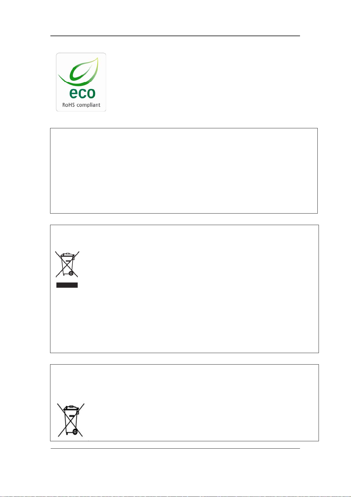
Samsung Techwin cares for the environment at all product
manufacturing stages, and is taking a number of steps to provide
customers with more environmentally friendly products. The Eco
mark represents Samsung Techwin’s will to create environmentally
friendly products, and indicates that the product satisfies the EU
RoHS Directive.
FCC Compliance Statement
NOTE : This equipment has been tested and found to comply with the limits for a Class A digital
device, pursuant to part 15 of the FCC Rules. These limits are designed to provide reasonable
protection against harmful interference when the equipment is operated in a commercial
environment. This equipment generates, uses, and can radiate radio frequency energy and, if not
installed and used in accordance with the instruction manual, may cause harmful interference to
radio communications. Operation of this equipment in a residential area is likely to cause harmful
interference in which cause the user will be required to correct the interference at his own expense.
Correct Disposal of This Product
(Waste Electrical & Electronic Equipment)
(Applicable in the European Union and other European countries with separate
collection systems.) This marking shown on the product or its literature, indicates that it
should not be disposed with other household wastes at the end of its working life. To
prevent possible harm to the environment or human health from uncontrolled waste
disposal, please separate this from other types of wastes and recycle it responsibly to promote the
sustainable reuse of material resources. Household users should contact either the retailer where
they purchased this product, or their local government office, for details of where and how they can
take this item for environmentally safe recycling. Business users should contact their supplier and
check the terms and conditions of the purchase contract. This product should not be mixed with
other commercial wastes for disposal.
Correct Disposal of Batteries in this Product
(Applicable in the European Union and other European countries with
separate battery return systems.)
This marking on the battery, manual or packaging indicates that the batteries in this
product should not be disposed of with other household waste at the end of their
working life. Where marked, the chemical symbols Hg, Cd or Pb indicate that the
battery contains mercury, cadmium or lead above the reference levels in EC
6

Install Manual
Directive 2006/66. If batteries are not properly disposed of, these substances can cause harm to
human health or the environment. To protect natural resources and to promote material reuse,
please separate batteries from other types of waste and recycle them through your local, free battery
return system. The rechargeable battery incorporated in this product is not user replaceable.
For information on its replacement, please contact your service provider.
7

Install Manual
Chapter 2. Summary
This unit is a digital video recording and playback device to record image and video input
from 32/16/9 channels to its built-in hard disk. The buttons on the front of the unit as well
as the mouse and GUI allow easy setup and operation.
The Samsung SVR series of digital video recorders (DVRs) provide additional safety and
security to banks, apartment buildings and complexes, government offices as well as
other public, private and commercial facilities. Recorded high-quality video and images
are stored on hard disk for later retrieval or playback. Real time functionality delivers
users with the ability to simultaneously record multiple channels, playback video, and
copy video. A few of the more advanced user-conveniences include motion detection,
Pan/Tilt/Zoom controls (PTZ), password protection, real time audio recording, event lists,
and log files.
2.1 Features
Monitoring Screen
The monitoring screen supports vivid, high-definition live visual feed from each channel and
provides multiple screens.
Real time MPEG-4 visual output (480 frames)
Multiple split-screen monitoring modes
SVR-3200/1680C/1660C/1645: Single, 4, 9, 10, 16
SVR-960C/945: Single, 4, 9
SVR-480 : Single, 4
Automatic Screen Switching (AUTO)
Supports various monitor output modes
SVR-3200: 4 Composite, 2 VGA
SVR-1680C: 4 Composite, 1 VGA
SVR-1660C/1645/960C/945/480: 2 Composite, 1 VGA
Pan/Tilt, Digital Zoom, PIP (Picture-In-Picture), The PIP function will be available with
a firmware upgrade in the future.
8

Install Manual
Audio Recording
SVR series DVRs provide real time audio recording.
Simultaneous recording of 16/9/4 channels of audio in real time
SVR-3200/1680C/1600/1645 : Input - 16 channels (4 RCA in rear, 12 D-SUB),
Output - 1 in rear, SVR-960C/945 : 9 channels (4 RCA in rear, 5 D-SUB),
Output - 1 in rear, SVR-480 : 4 channels (4RCA), Output – 1 in rear
Supports simultaneous recording and playback
Video Recording
The product is capable of storing visual image data as high resolution MPEG-4 video at up
to 480 frames per second, as well as pre-emptively initiating recording sequences up to five
seconds prior to an event. The COVERT feature (concealment of private visual data) helps
to protect privacy.
High quality real time MPEG-4 recording
Three screen-resolution levels for improved control over data sizes
Multi-recording for manual and scheduled events
Simultaneous recording/playback/backup/networking
Easily accessible options for channel-specific resolution and motion detection ranges
Per-second frame rates (up to 30 frames per channel) are user customizable
SVR-3200 Half D1 : NTSC (704x240) 960fps, PAL (704x288) 800fps
SVR-1680C D1 : NTSC (704x480) 480fps, PAL (704x576) 400fps
SVR-1660C/1645 CIF : NTSC (352x240) 480fps, PAL (352x288) 400fps
SVR-960C/945 CIF : NTSC (352x240) 270fps, PAL (352x288) 225fps
SVR-480 D1 : NTSC (704x480) 120fps, PAL (704x576) 100fps
Manual and scheduled recording
Video signal loss detection
Event logs (sensors, D-I/O, video loss, motion detection, text)
9

Install Manual
Each channel supports pre-emptive recording sequences up to 5 seconds prior to an
actual event
Search/Playback
Various search and playback options are offered for the user’s convenience.
Playback by time, date and channel
Mouse interface increases data searchability
Forward/backward search while playback is paused
Playback by event log entry (sensor, video loss, motion detection and text)
Remote controller and Jog/Shuttle further improve searching (The SVR-
960C/945/480 models do not support Jog/Shuttle.)
Full-frame playback (Available in SVR-3200/1680C/1660C only)
Data Storage
The hard disk included with the product is for data storage. If desired, recorded data can be
backed up or stored to DVD-R, CD-R or a USB storage device.
The built-in hard disk is provided as primary storage
Multiple portable data storage media are supported: DVD-R, CD-R and USB
※ Refer to the appendix on the back of the manual regarding compatible media types.
Hard disk expansion device (external recording device): SVS-5E (optional) External
hard disk expansion is supported with the SVS-5E (Available for purchase separately)
10

Install Manual
Networking
The product supports LAN, xDSL and other networking capabilities. Combined with the PC
interface client, the core features of the device can be easily remotely controlled.
E-mails can be sent via TCP/IP or DHCP upon an event trigger
Remote live visual feed (single or 4 section split-screen)
PC playback, storage, search and DVR control functions via Network Viewer
Remote recording, search and playback scheduling
Supports 10/100Mbps Ethernet/xDSL
Multiple DVR connections
Miscellaneous
User-friendly GUI and mouse interface
Simplified firmware upgrades through USB
Visual data recording and backup to USB
Supports PTZ control (SPEED DOME), Coax, PRESET
Multilingual support: Korean, English, Italian, Spanish, Japanese
Single remote controller to control 16 DVRs
11
Install Manual
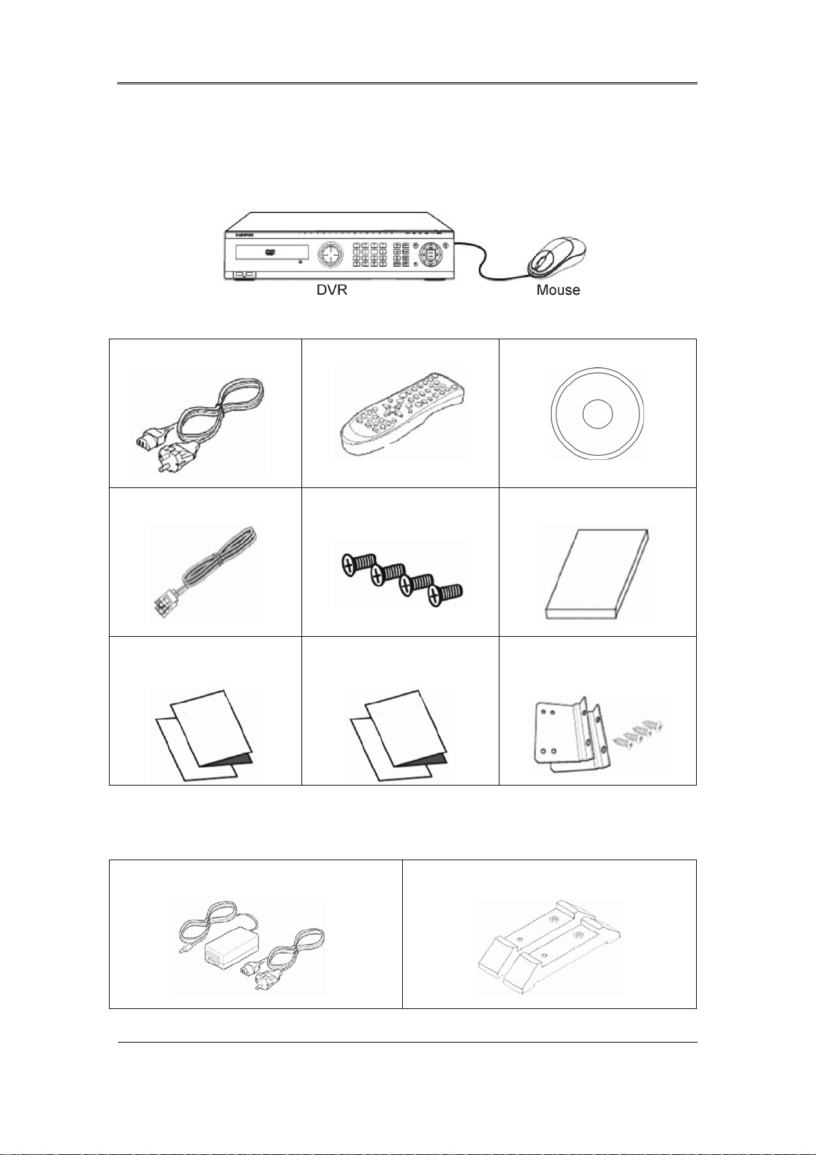
2.1 Components
Please check the included accessories as follows.
AC CORD
SATA Cable
DVR Quickguide
Remote Controller
HDD Mount Screw
SNM-128S Quickguide
Program CD
Install Manual
Rackmount & Screw
For the SVR-945, a switched-mode power supply (SMPS) power cord is included, while a stand
is included instead of the standard rack mount. SVR-480 does not include rack mount & Screw.
AC CORD & SMPS
12
STAND
Install Manual
2.2 Description of product
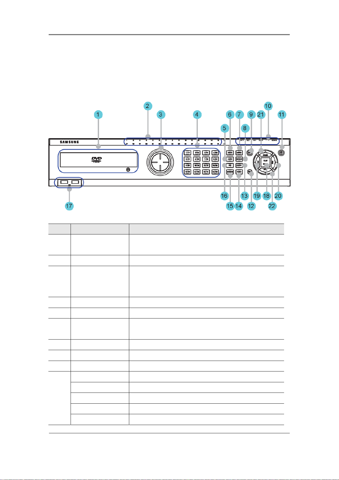
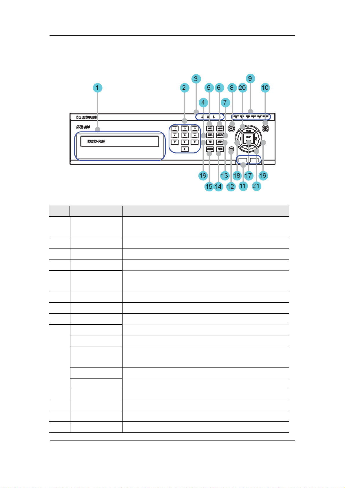
2.2.1 Front view
2.2.1.1 SVR-3200
No. Classification Function
DVD-Multi for
1
copying
2 Channel LED Shows the data input and event operation status
3 JOG/SHUTTLE
4 Channel button Selects channel in live feed or playback
5 AUTO Starts or stops user defined sequences.
6 MULTI Changes split-screen sections for live video feeds or
7 MENU Navigates into the Menu.
8 SEARCH Starts Search mode.
9 REC button Starts or stops manual recording
For copying recorded video and images to DVD/CD
optical media.
Jog can adjust setting values, control the STEP function,
navigate through the menu, and adjust the playback
speed and direction. Shuttle controls PTZ.
playback.
10
REC lamp Lit when recording.
HDD lamp Lit when HDD is working.
NETWORK lamp Lit when network is connected.
EVENT lamp Lit when an event is detected.
COPY lamp Indicates copying operation.
13

Install Manual
PLAY lamp Lit when copying.
11 Power button Turns on or off the device.
12 ESC button The Escape button navigates up the menu tree and
closes dialog windows.
13 COPY Starts Copy mode.
14 FUNC Starts Function mode.
15 MONITOR Cycles through from Monitor 1 to 4.
16 PTZ Starts or ends PTZ function.
17
USB ports for external devices (mouse, USB memory
USB1, USB2
stick).
18 PLAY/ENTER Start playback or select an item on the menu.
19
◀/REW
Navigates or selects in the menu, or for playback,
changes the reverse playback speed.
20
▶/FWD
Navigates or selects in the menu, or for playback,
changes the forward playback speed.
31 ▲/PAUSE Navigates or selects in the menu, or for playback,
pauses live or recorded video.
▼/STOP Navigates or selects in the menu, or for playback, stops
22
playback.
14
Install Manual
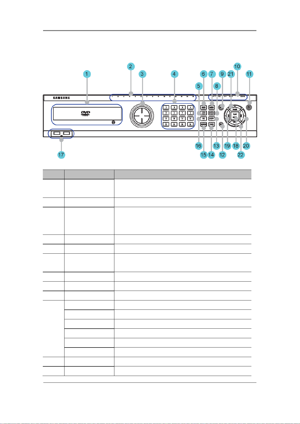
2.2.1.2 SVR-1680C, SVR-1660C, SVR-1645
No. Classification Function
DVD-Multi for
1
copying
2 Channel LED Shows the data input and event operation status
3 JOG/SHUTTLE
4 Channel button Selects channel in live feed or playback
5 AUTO Starts or stops user defined sequences.
6 MULTI Changes split-screen sections for live video feeds or
7 MENU Navigates into the Menu.
8 SEARCH Starts Search mode.
9 REC button Starts or stops manual recording
REC lamp Lit when recording.
HDD lamp Lit when HDD is working.
For copying recorded video and images to DVD/CD
optical media.
Jog can adjust setting values, control the STEP function,
navigate through the menu, and adjust the playback
speed and direction. Shuttle controls PTZ.
playback.
10
NETWORK lamp Lit when network is connected.
EVENT lamp Lit when an event is detected.
COPY lamp Indicates copying operation.
PLAY lamp Lit when copying.
11 Power button Turns on or off the device.
12 ESC button The Escape button navigates up the menu tree and
15

Install Manual
closes dialog windows.
13 COPY Starts Copy mode.
14 FUNC Starts Function mode.
15 MONITOR Cycles through from Monitor 1 to 4 : SVR-1680C,
Switches from main and sub monitor : SVR-1660C,
SVR-1645
16 PTZ Starts or ends PTZ function.
17
USB ports for external devices (mouse, USB memory
USB1, USB2
stick).
18 PLAY/ENTER Start playback or select an item on the menu.
19
◀/REW
Navigates or selects in the menu, or for playback,
changes the reverse playback speed.
20
▶/FWD
Navigates or selects in the menu, or for playback,
changes the forward playback speed.
31 ▲/PAUSE Navigates or selects in the menu, or for playback,
pauses live or recorded video.
▼/STOP Navigates or selects in the menu, or for playback, stops
22
playback.
16
Install Manual
r
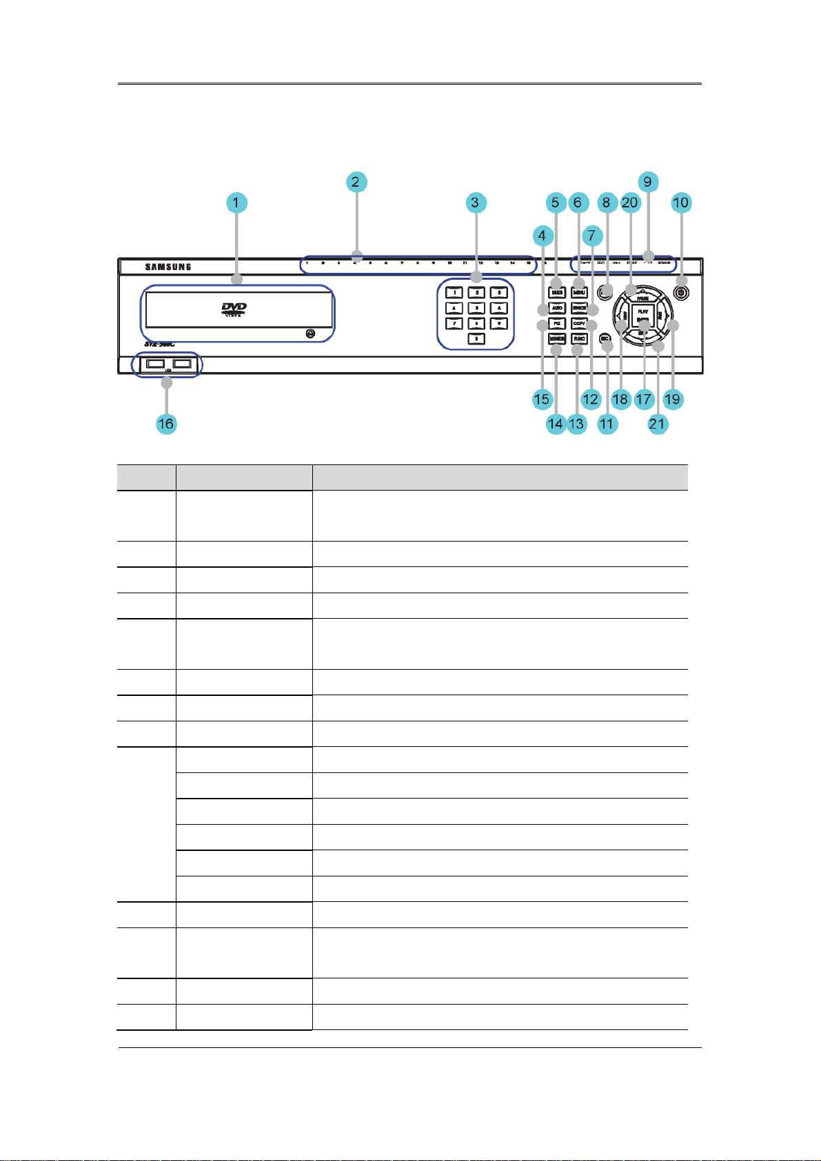
2.2.1.3 SVR-960C
No. Classification Function
DVD-Multi fo
1
copying
2 Channel LED Shows the data input and event operation status
3 Channel button Selects channel in live feed or playback
4 AUTO Starts or stops user defined sequences.
5 MULTI Changes split-screen sections for live video feeds or
6 MENU Navigates into the Menu.
7 SEARCH Starts Search mode.
8 REC button Starts or stops manual recording
REC lamp Lit when recording.
HDD lamp Lit when HDD is working.
NETWORK lamp Lit when network is connected.
9
EVENT lamp Lit when an event is detected.
COPY lamp Indicates copying operation.
For copying recorded video and images to DVD/CD
optical media.
playback.
PLAY lamp Lit when copying.
10 Power button Turns on or off the device.
11 ESC button The Escape button navigates up the menu tree and
closes dialog windows.
12 COPY Starts Copy mode.
13 FUNC Starts Function mode.
17

Install Manual
14 MONITOR Switches from main and sub monitor
15 PTZ Starts or ends PTZ function.
16
USB ports for external devices (mouse, USB memory
USB1, USB2
stick).
17 PLAY/ENTER Start playback or select an item on the menu.
18
◀/REW
Navigates or selects in the menu, or for playback,
changes the reverse playback speed.
19
▶/FWD
Navigates or selects in the menu, or for playback,
changes the forward playback speed.
20 ▲/PAUSE Navigates or selects in the menu, or for playback,
pauses live or recorded video.
▼/STOP Navigates or selects in the menu, or for playback, stops
21
playback.
18
Install Manual
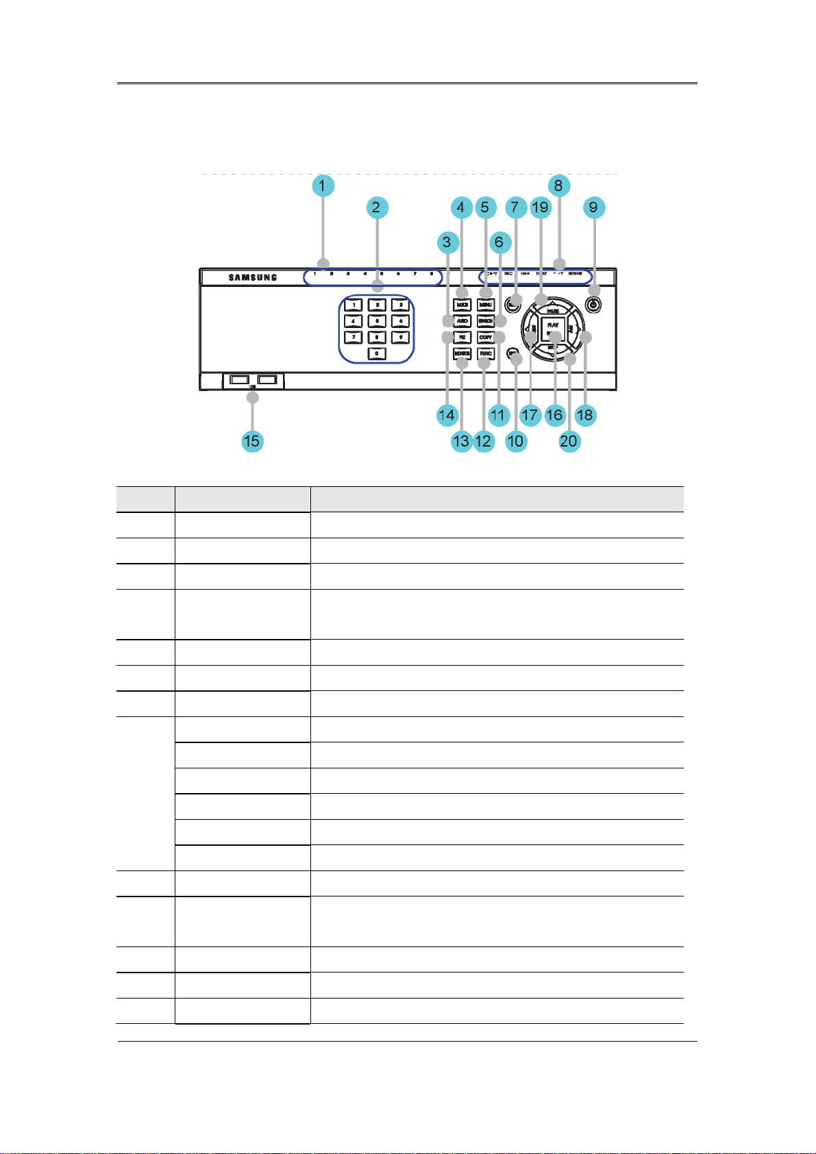
2.2.1.4 SVR-945
No. Classification Function
1 Channel LED Shows the data input and event operation status
2 Channel button Selects channel in live feed or playback
3 AUTO Starts or stops user defined sequences.
4 MULTI Changes split-screen sections for live video feeds or
playback.
5 MENU Navigates into the Menu.
6 SEARCH Starts Search mode.
7 REC button Starts or stops manual recording
REC lamp Lit when recording.
HDD lamp Lit when HDD is working.
8
NETWORK lamp Lit when network is connected.
EVENT lamp Lit when an event is detected.
COPY lamp Indicates copying operation.
PLAY lamp Lit when copying.
9 Power button Turns on or off the device.
10 ESC button The Escape button navigates up the menu tree and
closes dialog windows.
11 COPY Starts Copy mode.
12 FUNC Starts Function mode.
13 MONITOR Switches from main and sub monitor
19

Install Manual
14 PTZ Starts or ends PTZ function.
15
USB ports for external devices (mouse, USB memory
USB1, USB2
stick).
16 PLAY/ENTER Start playback or select an item on the menu.
17
◀/REW
Navigates or selects in the menu, or for playback,
changes the reverse playback speed.
18
▶/FWD
Navigates or selects in the menu, or for playback,
changes the forward playback speed.
19 ▲/PAUSE Navigates or selects in the menu, or for playback,
pauses live or recorded video.
▼/STOP Navigates or selects in the menu, or for playback, stops
20
playback.
20
Install Manual
r
2.2.1.5 SVR-480
No Classification Function
DVD-Multi fo
1
copying
2 Channel button Selects channel in live feed or playback
3 Channel LED Shows the data input and event operation status
4 AUTO Starts or stops user defined sequences.
5 MULTI Changes split-screen sections for live video feeds or
6 MENU Navigates into the Menu.
7 SEARCH Starts Search mode.
8 REC button Starts or stops manual recording
REC lamp Lit when recording.
HDD lamp Lit when HDD is working.
NETWORK
9
lamp
For copying recorded video and images to DVD/CD optical
media.
playback.
Lit when network is connected.
EVENT lamp Lit when an event is detected.
COPY lamp Indicates copying operation.
PLAY lamp Lit when copying.
10 Power button Turns on or off the device.
11 USB1, USB2 USB ports for external devices (mouse, USB memory stick).
12 ESC button The Escape button navigates up the menu tree and closes
21

Install Manual
dialog windows.
13 COPY Starts Copy mode.
14 FUNC Starts Function mode.
15 MONITOR Switches from main and sub monitor
16 PTZ Starts or ends PTZ function.
17 PLAY/ENTER Start playback or select an item on the menu.
18
◀/REW
Navigates or selects in the menu, or for playback, changes
the reverse playback speed.
19
▶/FWD
Navigates or selects in the menu, or for playback, changes
the forward playback speed.
20 ▲/PAUSE Navigates or selects in the menu, or for playback, pauses
live or recorded video.
▼/STOP Navigates or selects in the menu, or for playback, stops
21
playback.
22
Install Manual
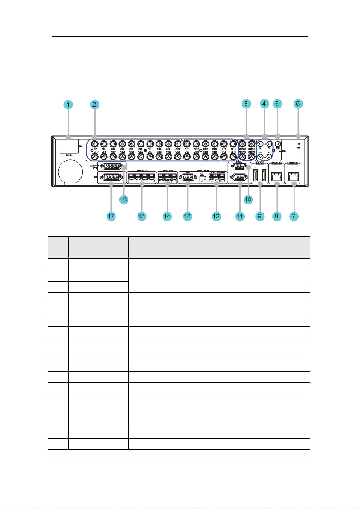
2.2.2 Rear Part
2.2.2.1 SVR-3200
No. Input/Output
terminal name
1 POWER IN Socket for AC 100V ~ AC 240V power cord.
2 CH1 ~ 32 Connection terminal for camera BNC input.
3 MONITOR 1 ~ 4 Connection terminal for monitor BNC output.
4 AUDIO IN(RCA) RCA audio jack for RCA input.
5 AUDIO OUT Audio jack for speaker output.
6 GROUND Ground terminal between DVR and external device.
7 ETHERNET Ethernet port for network connections (RJ-45).
8 STORAGE External storage connection port (Function not supported in the
current version)
9 eSATA Connection terminal for external eSATA HDD or HDD for backups.
10 VGA OUTPUT 2 Output port for PC monitor.
11 VGA OUTPUT 1 Output port for PC monitor.
Function
12 Serial Port (Terminal
Block)
RS-232C/485/422
13 Serial Port (D-Sub) RS-232C D-SUB connector.
14 RELAY OUT Connection terminal for relay output.
Connection terminal for expanded controller, speed dome camera,
etc.
23

Install Manual
15 SENSOR IN Connection terminal for sensor input.
16 AUDIO IN(D-SUB) Connection terminal for audio output D-SUB.
17 D-I/O Connection terminal for DIGITAL IN/OUT.
24
Install Manual
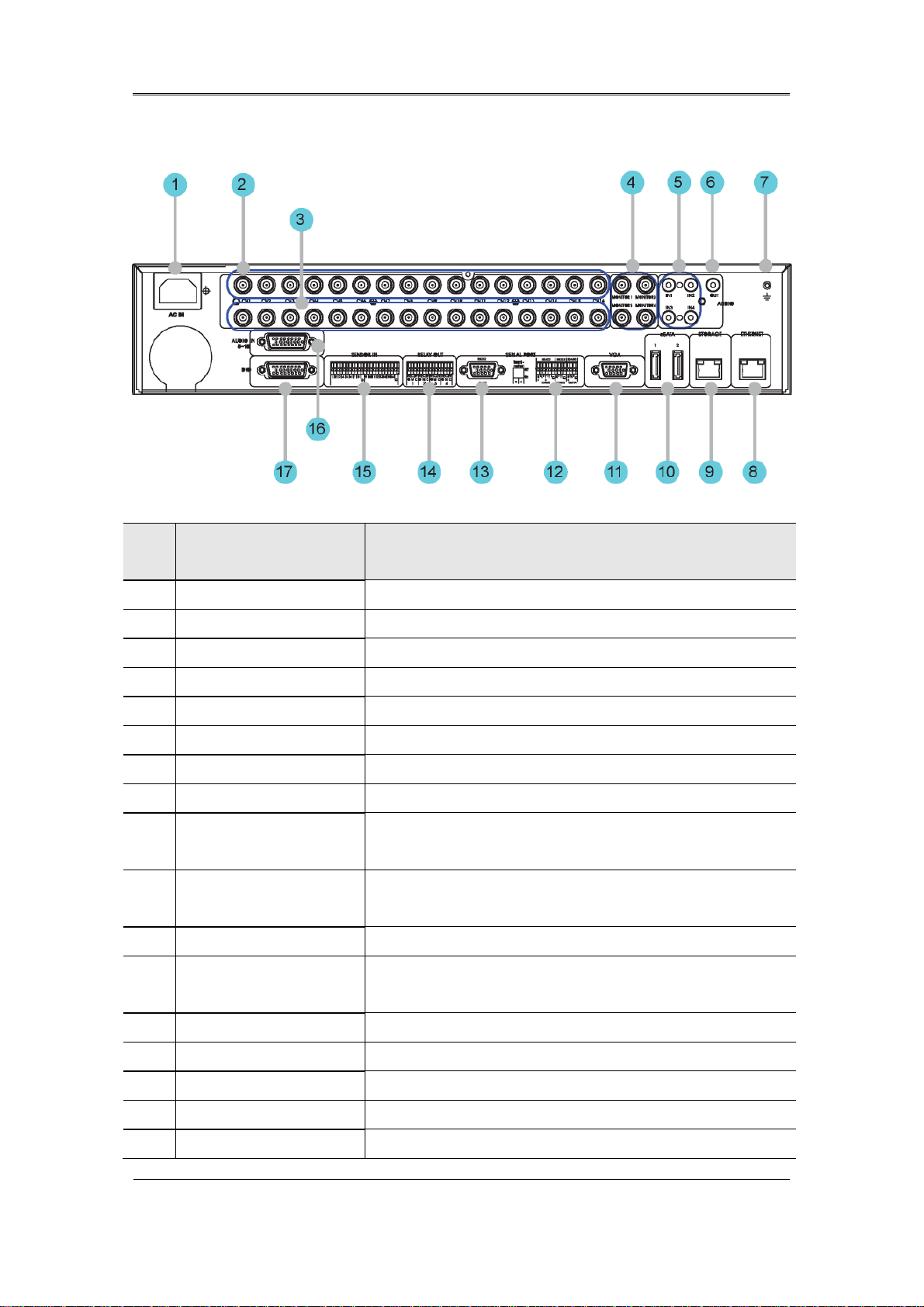
2.2.2.2 SVR-1680C, SVR-1660C, SVR-1645
No. Input/Output
terminal name
1 POWER IN Socket for AC 100V ~ AC 240V power cord.
2 CH1~16 Connection terminal for camera BNC input.
3 LOOP OUT Connection terminal for camera BNC output (loop).
4 MONITOR 1 ~ 2 Connection terminal for monitor BNC output.
5 AUDIO IN(RCA) RCA audio jack for RCA input.
6 AUDIO OUT Audio jack for speaker output.
7 GROUND Ground terminal between DVR and external device.
8 ETHERNET Ethernet port for network connections (RJ-45).
9 STORAGE External storage connection port (Function not supported in
the current version)
10 eSATA Connection terminal for external eSATA HDD or HDD for
backups.
11 VGA OUTPUT Output port for PC monitor.
12 Serial Port (Terminal
Connection terminal for expanded controller, speed dome
Function
Block) RS-232C/485/422
13 Serial Port (D-Sub) RS-232C D-SUB connector.
14 RELAY OUT Connection terminal for relay output.
15 SENSOR IN Connection terminal for sensor input.
16 AUDIO IN(D-SUB) Connection terminal for audio output D-SUB.
17 D-I/O Connection terminal for DIGITAL IN/OUT.
camera, etc.
25
Install Manual
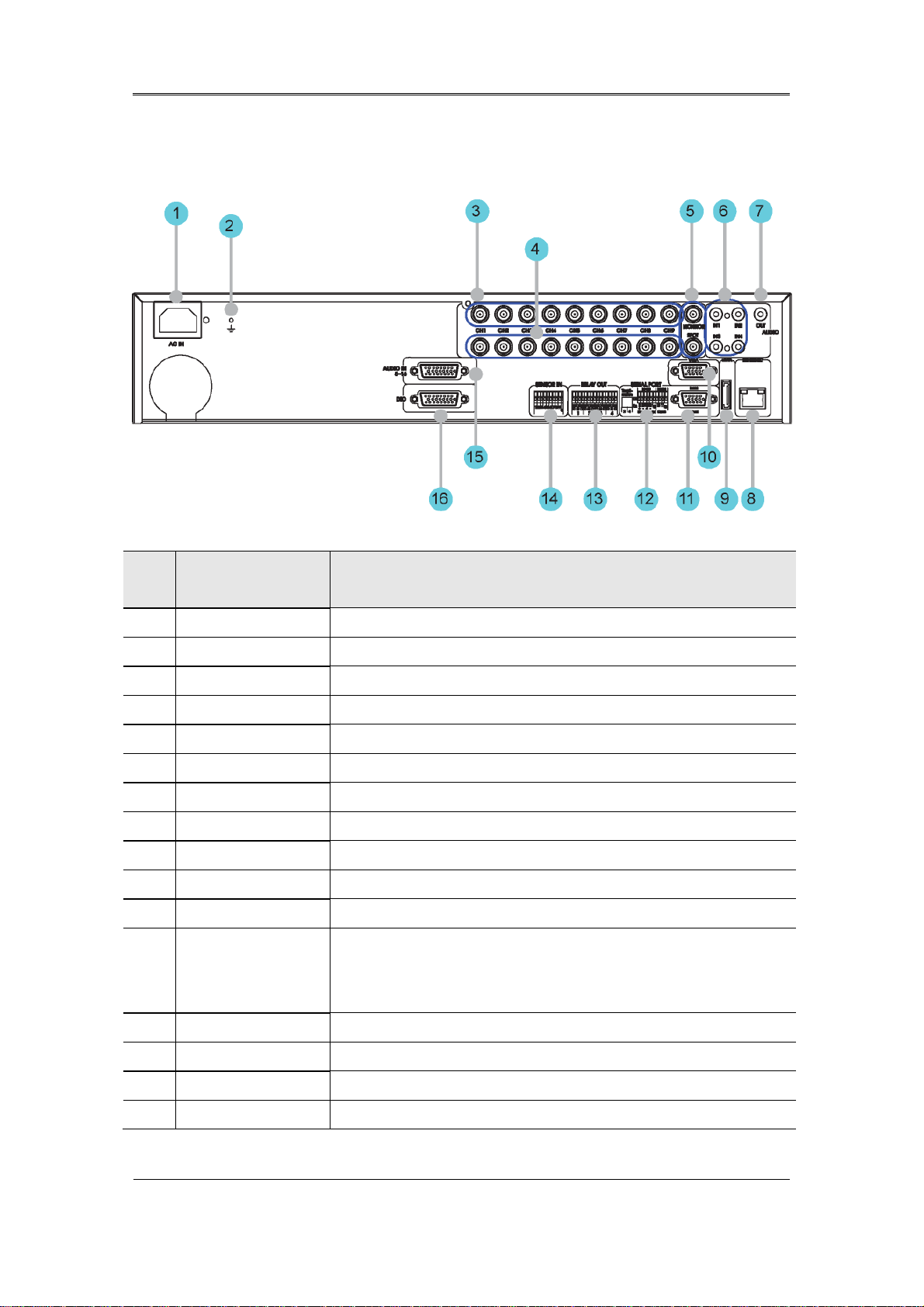
2.2.2.3 SVR-960C
No. Input/Output
terminal name
1 POWER IN Socket for AC 100V ~ AC 240V power cord.
2 GROUND Ground terminal between DVR and external device.
3 CH1~9 Connection terminal for camera BNC input.
4 LOOP OUT Connection terminal for camera BNC output (loop).
5 MONITOR 1 ~ 2 Connection terminal for monitor BNC output.
6 AUDIO IN(RCA) RCA audio jack for RCA input.
7 AUDIO OUT Audio jack for speaker output.
8 ETHERNET Ethernet port for network connections (RJ-45).
9 eSATA Connection terminal for external eSATA HDD or HDD for backups.
10 VGA OUTPUT Output port for PC monitor.
11 Serial Port (D-Sub) RS-232C D-SUB connector.
12 Serial Port (Terminal
Block)
Connection terminal for expanded controller, speed dome camera,
etc.
Function
RS-232C/485/422
13 RELAY OUT Connection terminal for relay output.
14 SENSOR IN Connection terminal for sensor input.
15 AUDIO IN(D-SUB) Connection terminal for audio output D-SUB.
16 D-I/O Connection terminal for DIGITAL IN/OUT.
26
 Loading...