

Samsung SVR1620 User Manual
WARNING
EXPLANATION OF GRAPHICAL SYMBOLS
This symbol is intended to alert the user to the presence of unprotected
“dangerous voltage" within the product's enclosure that may be strong
enough to cause a risk of electric shock persons.
This symbol is intended to alert the user to the presence of
important operating and maintenance (servicing)
instructions in the literature accompanying the appliance.
WARNING
TO REDUCE THE RISK OF FIRE OR ELECTRIC SHOCK, DO NOT EXPOSE THIS
APPLIANCE TO RAIN OR MOISTURE.
NOTE: This equipment has been tested and found to comply with the limits for a class a digital
device, pursuant to part 15 of the FCC Rules. These limits are designed to provide
reasonable protection against harmful interference when the equipment is operated in
a commercial environment. This equipment generates, uses, and can radiate radio
frequency energy and, if not installed and used in accordance with the instruction
manual, may cause harmful interference to radio communications. Operation of this
equipment in a residential area is likely to cause harmful interference in which case the
user will be required to correct the interference at his own expense.
DIGITAL VIDEO RECORDER
1

PRECAUTION
• Make sure to switch the power off before you install the DVR.
• There is the danger of an electric shock if the DVR is opened by an unqualified service
engineer or installer.
• Avoid using the DVR outside of the reference temperature and humidity indicated in the
specification.
• Avoid exposing the DVR to violent movement or vibration.
• Do not use or store the DVR in direct sunlight or near to any source of heat.
• Do not place any object into the holes used for air circulation.
• Before connecting the power cord, please select the correct voltage for local use . You
may switch between 230VAC and 115VAC.
• Always use the DVR in a well ventilated location to prevent overheating.
• When the system is overheated, the below warning message will be displayed
at the monitor.
“ OUT OF TEMPERATURE”
In this case, do the power off right away and check the cooling fan working.
• The HDD is recommended to use Enhanced IDE Hard Disc Drive type made by
Western Digital and Samsung Electronics.
For more information, refer to “Specification”.
◈ EXTRA HDD BAY (If specified as an accessory)
• Always attach the joining cable lead between the DVR and the HDD Bay for correct
system management.(Refer to the section describing the installation procedure for the
EXTRA HDD BAY)
• While the EXTRA HDD BAY is in operation never disconnect the power or connecting
cable. Before opening the top cover you must turn off the power by the switch on the
front panel of the DVR. Then disconnect the power cord and other cables. Failure to
follow this procedure will result in lost data and possible malfunction of the system.
• When replacing any HDD always make certain that the replacement part is fitted in the
same place and with the same connections as the original.
2
USER’S MANUAL

TABLE OF CONTENT
FEATURE LIST -----------------------------------------------------------------------------------------------------------
PACKING DETAIL -------------------------------------------------------------------------------------------------------
LOCATION OF PART AND CONTROL ----------------------------------------------------------------------------
FRONT PANEL CONTROLS -------------------------------------------------------------------------------
REAR PANEL CONNECTORS ---------------------------------------------------------------------------------
INSTALLATION -----------------------------------------------------------------------------------------------------------
TOTAL CONNECTION LAY-OUT -------------------------------------------------------------------------
INDIVIDUAL CONNECTION --------------------------------------------------------------------------------
RACK MOUNT --------------------------------------------------------------------------------------
CAMERA ---------------------------------------------------------------------------------------------
AUDIO ------------------------------------------------------------------------------------------------
MONITOR --------------------------------------------------------------------------------------------
POWER -----------------------------------------------------------------------------------------------
EXTRA HDD BAY------------------------------------------------------------------------------------
OPERATION ---------------------------------------------------------------------------------------------------------------
FACTORY DEFAULT ----------------------------------------------------------------------------------------
POWER ON / OFF --------------------------------------------------------------------------------------------
SCREEN DISPLAY -------------------------------------------------------------------------------------------
RECORD --------------------------------------------------------------------------------------------------------
PLAYBACK ----------------------------------------------------------------------------------------------------
SEARCH BUTTON INFORMATION ----------------------------------------------------------------------
JOG SHUTTLE INFORMATION ---------------------------------------------------------------------------
DIGITAL ZOOM----------------------------------------------------------------------------------------------
SCREEN SELECT---------------------------------------------------------------------------------------------
COPY -------------------------------------------------------------------------------------------------------------
SYSTEM INFORMATION -----------------------------------------------------------------------------------
PTZ CONTROL-----------------------------------------------------------------------------------------------------
PIP -----------------------------------------------------------------------------------------------------------------
REMOTE CONTROLLER-----------------------------------------------------------------------------------
SETUP MENU -------------------------------------------------------------------------------------------------------------
ENTRANCE OF THE SVR-1620 ETUP ---------------------------------------------------------------
SCREEN SETUP-----------------------------------------------------------------------------------------------
RECORD SETUP----------------------------------------------------------------------------------------------
EV EN T SETUP---------------------- -------------------------------------- -------------------------------------- --
SYSTEM SETUP------------------------------------------------------------------------------------------------
CLOCK SETUP-------------------------------------------------------------------------------------------------
LOAD SETUP DEFAULT ------------------------------------------------------------------------------------
EXIT WITH SAVE ---------------------------------------------------------------------------------------------
EXIT ---------------------------------------------------------------------------------------------------------------
EXTERNAL TERMINAL INFORMATION --------------------------------------------------------------------------
POWER OUT-----------------------------------------------------------------------------------------------------
RELAY OUT----------------------------------------------------------------------------------------------------------
ALARM -------------------------------------------------------------------------------------------------------------
RS-422/RS-485--------------------------------------------------------------------------------------------------
RS-232C ---------------------------------------------------------------------------------------------------------
ETHERNET 10/100 BASE-T-----------------------------------------------------------------------------------
VGA-----------------------------------------------------------------------------------------------------------------
REMOTE-------------------------------------------------------------------------------------------------------------
SPECIFICATION ----------------------------------------------------------------------------------------------------------
10
11
11
12
14
14
16
16
18
18
22
23
24
24
25
28
29
30
31
32
32
32
38
43
49
59
59
60
60
61
61
61
62
62
63
63
64
64
66
4
5
6
6
7
8
8
9
9
9
DIGITAL VIDEO RECORDER
3

FEATURE LIST
DISPLAY
Real Time Single or Multi Screen Display
Auto Sequence Switching
Instant Switching from Live Display to Playback Display
Pan/Tilt, Digital Zoom and PIP Display
RECORDING
Simultaneous Record, Playback & Record Backup (Triplex)
Easy, User Friendly Set-up Menus
Up to 8 Different Record Quality Grade
Individual Camera Frame or Field Rate can be set by User
Full 60 Images per Second Recording Speed
Manual & Scheduled Recording Option
Event Recording by Motion Detection or External Alarm
Video Loss Detection
Event List for MD and Alarm Modes
Pre-alarm Recording up to 5 seconds
NETWORK(Optional)
View Live & Recorded video on a networked PC with Viewer Software
Support Flexible connections - 10/100 Mbps Ethernet / ADSL
PLAYBACK
Replay by Date, Time and Camera
Frame by Frame or Field by Field Replay
Easy Replay Operation by IR Remote Control and Jog / Shuttle
ARCHIVING
Digital Backup to Removable Hard Disk Drive
Auto Backup to R-HDD by User Setting for Event Recording on Alarm
GENERAL
Additional Hard Disk Drives can be added with Accessory HDD Bay
Software Download facility by PC
Auto Detect PAL / NTSC
Selectable Real Time Audio Recording
VGA Output available
4
USER’S MANUAL
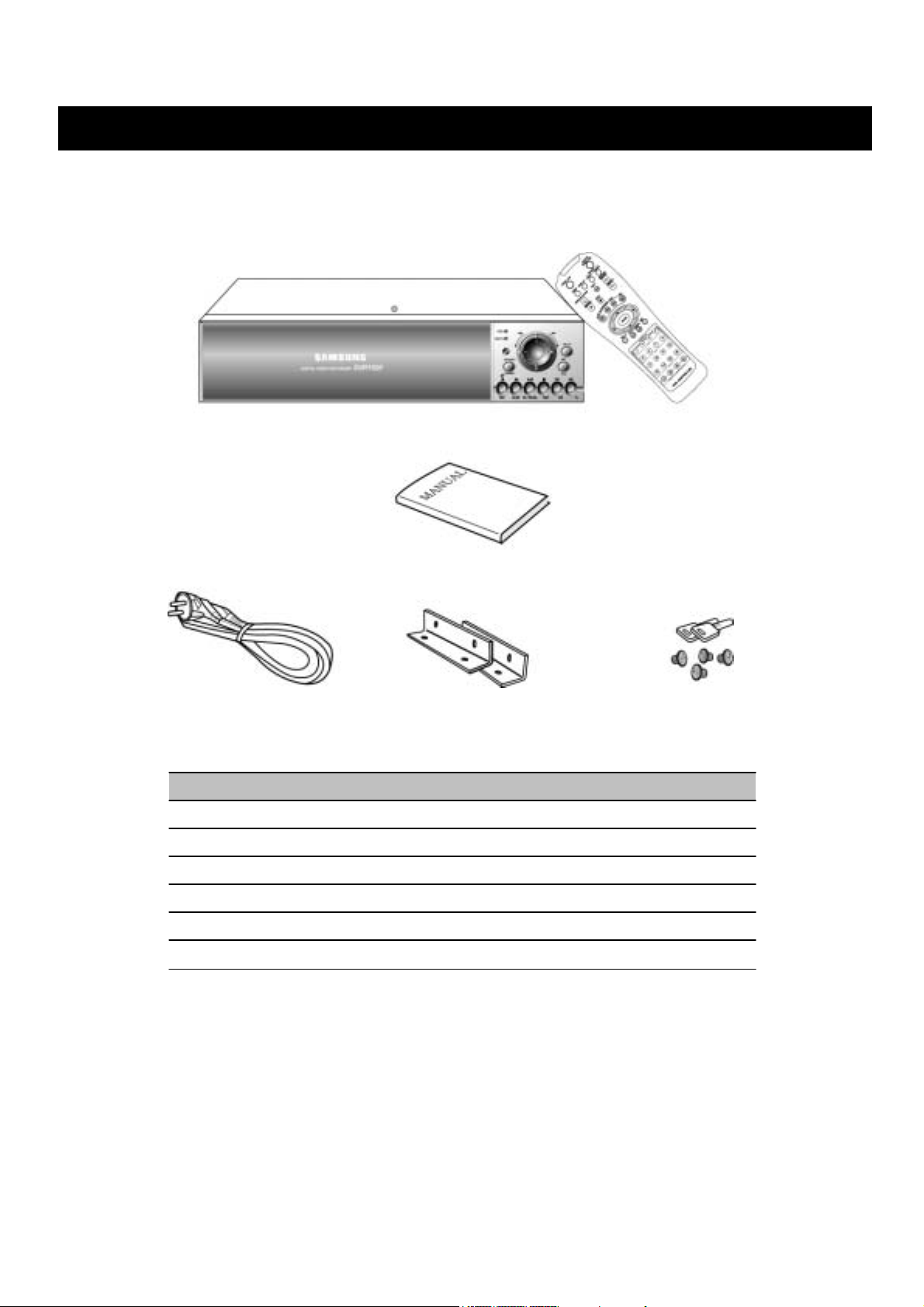
PACKING DETAIL
1. SVR1620
2. Remote Controller
3. User’s Manual
4. Power Cord (230V A C & 115AC)
5. Rack Mount
6. R-HDD Rack Key & Screw for R-HDD Installation
1. SVR1620
3. Manual
5. Rack Mount
2. Remote Controller
6. R-HDD Rack Key & Screw4. Power Cord
DIGITAL VIDEO RECORDER
5
LOCATION OF PART AND CONTROL
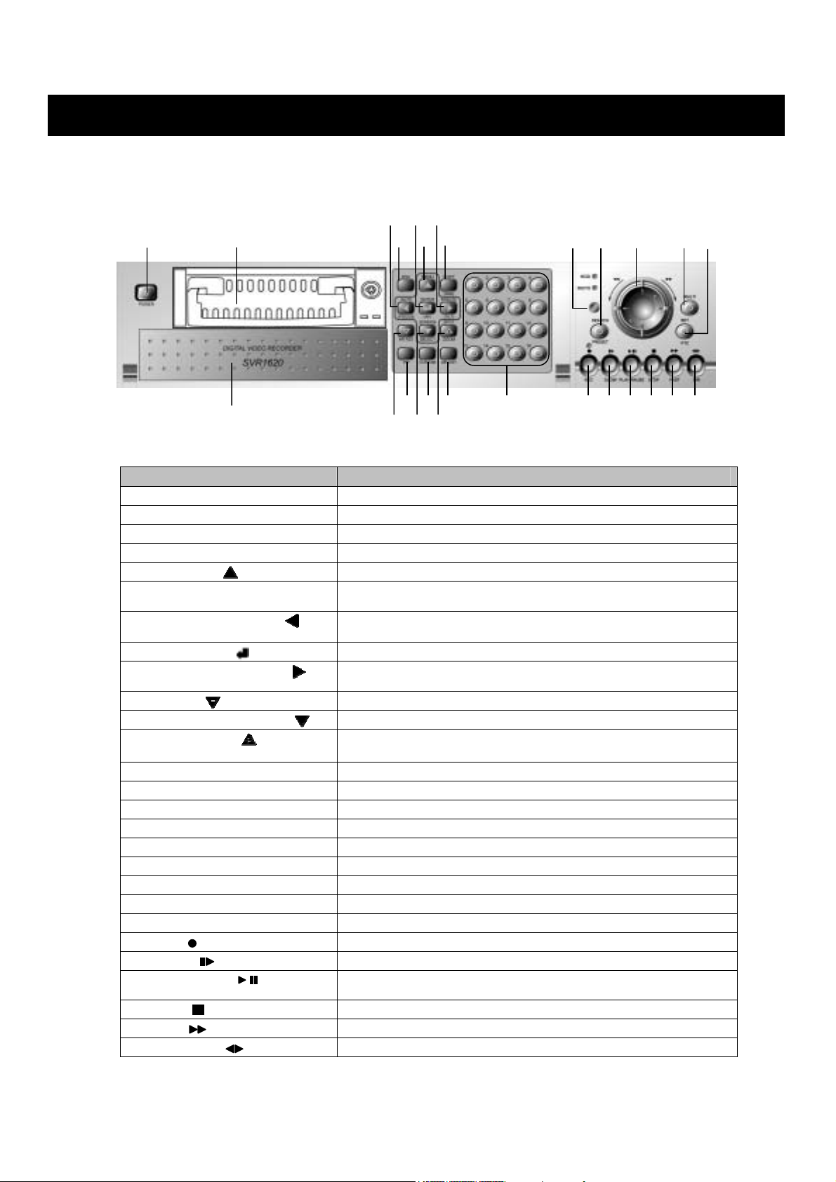
FRONT PANEL CONTROLS
1
○
○2 ○4○
3
○
Button Name Description
○1 POWER SWITCH
○2 R.HDD RACK
○3 Internal HDD Tray
○4 ESC
○5 MENU / UP( )
○6 COPY(PAN)
○7 AUTO(FOCUS) / LEFT( )
○8 ENTER(AF) / ( )
○9 FREEZE(TILT) / RIGHT( )
○10 AR RST( )
○11 SCREEN SELECT/ DOWN( )
○12 SPOT / ZOOM( )
○13 PIP
○14 D ZOOM
○15 AR LIST
○16 CHANNEL SELECT
○17 REMOTE SENSER
○18 SEARCH / PRESET
○19 JOG / SHUTTLE
○20 MULTI
○21 SET / PTZ
○22 REC( )
○23 SLOW( )
○24 PLAY / PAUSE( )
25
○
STOP( )
26
○
FAST( )
27
○
DIRECTION( )
○7○8○
10
○
Press this button to turn the power on / off
Removable HDD rack for digital backup
Two internal HDD tray
Press this button to return to the previous menu
Press this button to display the setup menu / upper direction
Press this button to display the copy menu / Pan left and right control
in PTZ mode
Press this button
Focus control in PTZ mode / Left direction
Enter / Auto focus in PTZ mode
Image freezing / Tilt up and down control in PTZ mode / Right
direction
Releasing the Event signal / Decreasing Parameter
Convert the screen display into real view mode during replay
Press this button to select spot Monitor /
Zoom Control in PTZ mode / Increasing Parameter
Press this button to control PIP function
Press this button to control digital zoom function
Press this button to display the event list menu
Camera select button
Input sensor for the remote controller
Press this button to display the search menu
Press this button to speed-up the playback speed
Press this button to select Multi channel
Press this button to enter PTZ control mode
Press this button to begin and stop recording
Press this button to slow-down playback speed
Press this button to commence playback. If press again, during
playback, a still picture is displayed
Press this button to exit the playback mode
Press this button to speed-up the playback speed
Press this button to change the direction of playback
13
○
○11○
9
5
6
○
15
14
○
○
12
to begin the auto sequence mode /
16
○
17
○18 ○19 ○
○
○22 ○24 ○23 ○25 ○26 ○
20
21
○
27
6
USER’S MANUAL
LOCATION OF PART AND CONTROL
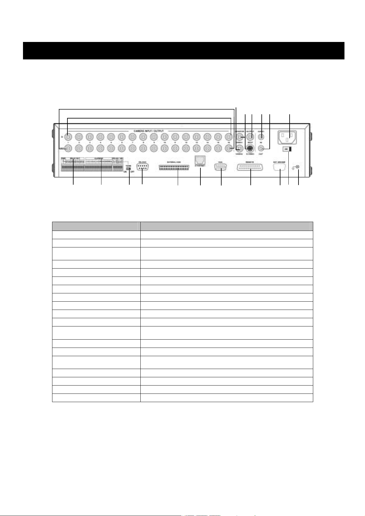
REAR PANEL CONNECTORS
9
○
10
○
Port Name Description
○1 CAMERA IN
○2 CAMERA OUT
○3 MONITOR OUT
4
○
VIDEO 2
○5 SPOT OUT
6
○
AUDIO IN
○7 AUDIO OUT
○8 POWER IN
○9 RELAY OUT
○10 ALARM IN
○11 TERMINATION
○12 RS-232C
○13 EXTERNAL HDD
○14 ETHERNET
○15 VGA
○16 REMOTE
○17 EXT. MODEM
○18 POWER SELECT
○19 GROUND
2
○
1
○
11
12
○
○
These are BNC input connectors for cameras
These are BNC output (looping) connectors for cameras
There are two Monitor output connectors: one BNC connector and
one SVHS connector
BNC output for external device
BNC output for spot monitor
Input connector for an audio signal
Output connector for an audio signal
This socket is for a 230-115VAC power cord
Relay output terminals
Input terminals for alarm signals
RS-485 termination
The recorder can be controlled by the other device through this
connector
This connector for the external HDD bay
Option
Output connector for VGA monitor
SVR-1620 is not compatible with TFT LCD monitor in PAL mode.
Reserved
Reserved
Select between 230VAC and 115VAC
Earth Ground connector for use with external HDD Bay
13
○
14
○
15
○
○
4
17
○
8
○
19
○18○
○
3
○5○
16
○
6
7
○
DIGITAL VIDEO RECORDER
7
INSTALLATION
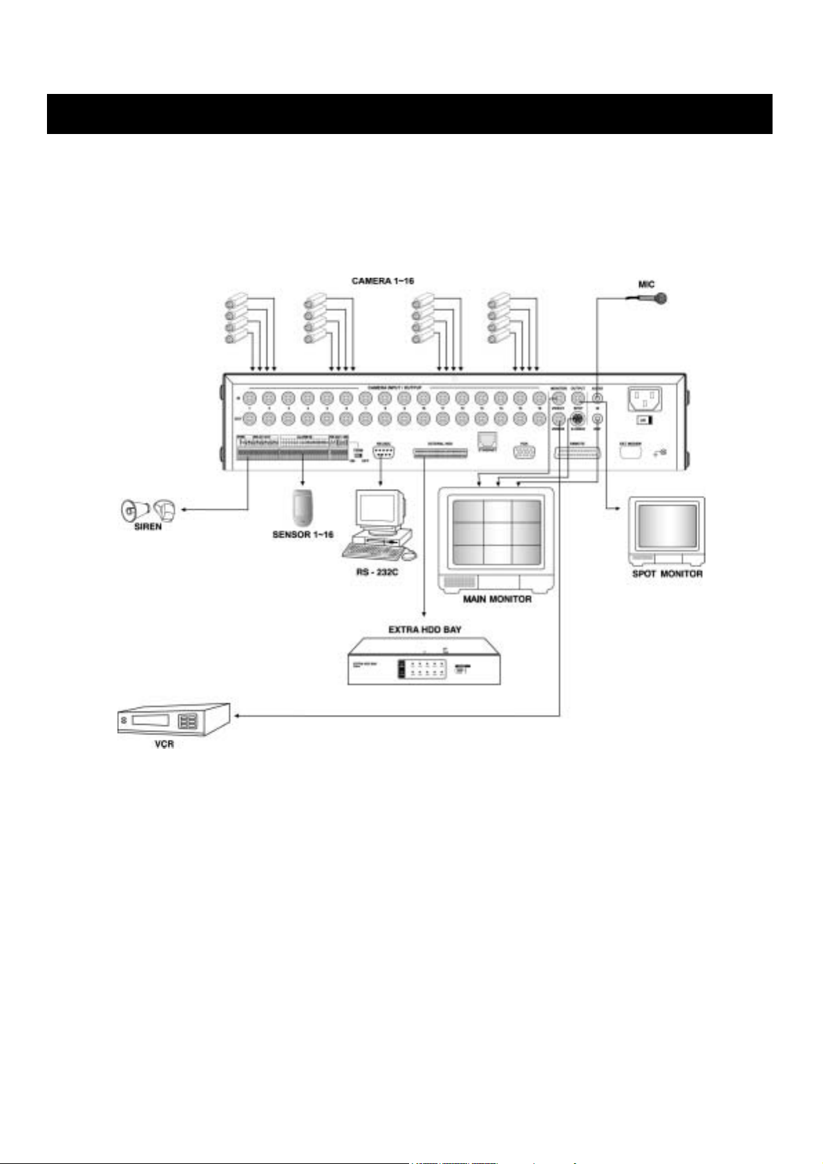
TOTAL CONNECTION LAY-OUT
8
USER’S MANUAL
A
A
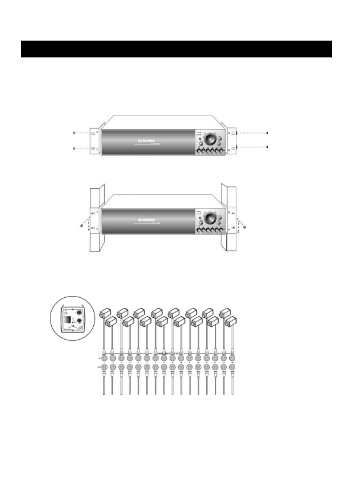
INSTALLATION
INDIVIDUAL CONNECTION
1. Rack mount
2. Camera
* Connect the female BNC from each camera to the male BNC on the “CAMERA IN” port
* Connect the looping BNC output to other inputs as required
dapt the supplied rack mount to DVR
dapt the DVR rack (19 inch)
DIGITAL VIDEO RECORDER
9

INSTALLATION
3. Audio *Refer to the specification
Audio Input
- AUDIO IN : Connect the RCA Line Jack from the relevant equipment (for example camera
with inbuilt Microphone) to the AUDIO IN port
Note : Please refer to the AUDIO setup at the main menu setup for input selection.
If the audio is recorded with images, audio can be re-played at that moment
Audio Output
- AUDIO OUT : Connect the RCA Line out to a monitor with an inbuilt speaker
in any type of screen division mode.
10
USER’S MANUAL
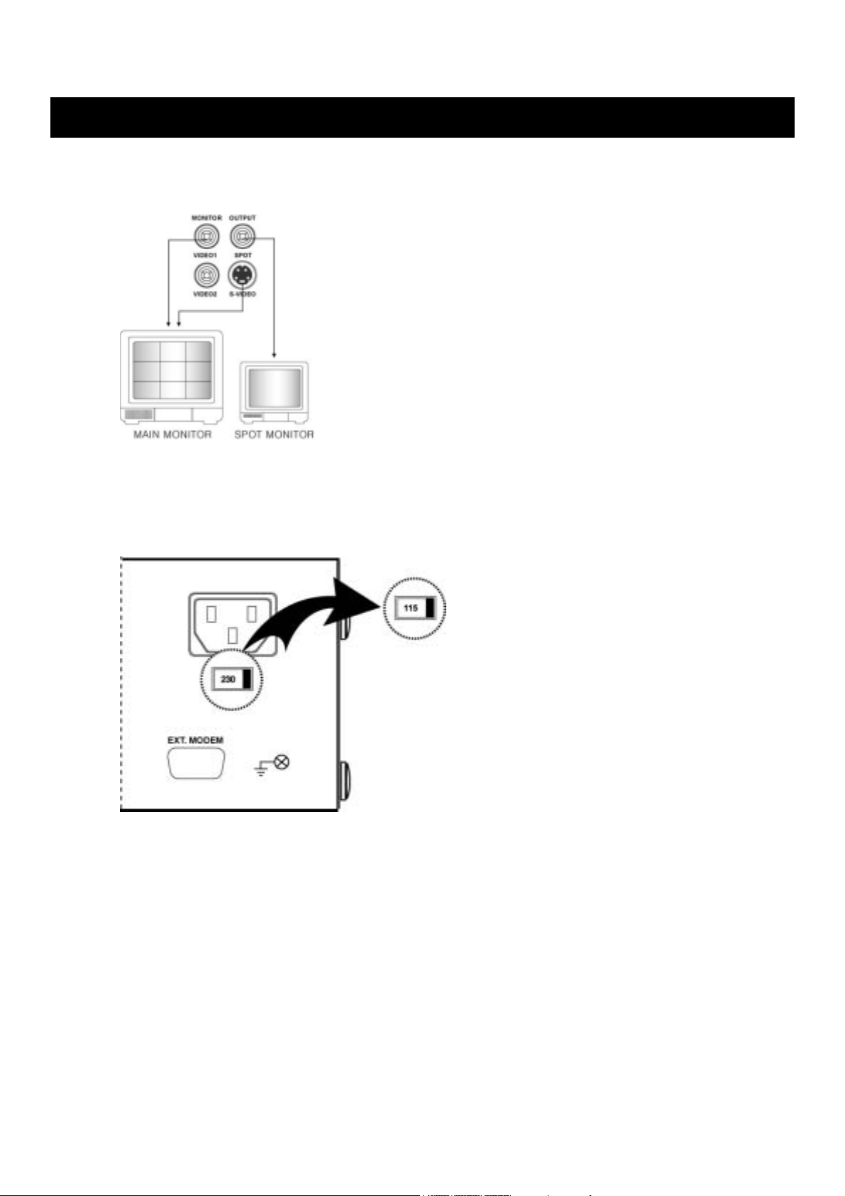
INSTALLATION
4. Monitor
- Connect the female BNC for monitor output.
- Connect the Y/C cable for S-VIDEO monitor output.
5. Power
- Select the correct voltage of power (230=180~265 VAC / 115=90~135 VAC)
- Connect the power cord.
DIGITAL VIDEO RECORDER
11
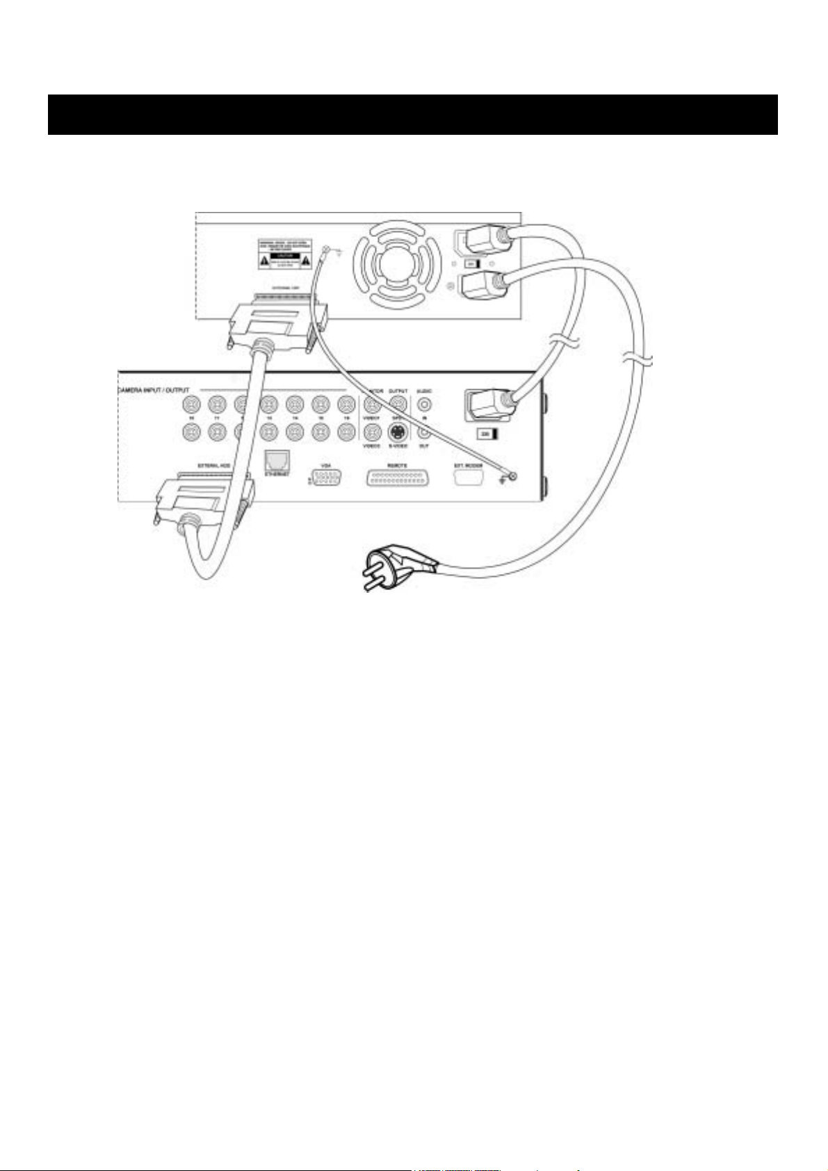
INSTALLATION
◈ INSTALLATION PROCESS.
1) Turn off the power of DVR.
2) Connect the Grounding conductor between DVR and EXTRA HDD Bay.
3) Connect the 68pins SCSI cable between DVR and EXTRA HDD Bay.
4) Plug the connecting cable into the inlet socket of the DVR and the outlet of
the EXTRA HDD Bay.
5) Connect the power cord to the inlet of EXTRA HDD Bay.
6) Turn the power of DVR on.
7) Af ter booting the system automatically, press the ENTER button and check the system
information of setting the HDD. (If the HDD is not recognized properly, turn the power of
DVR off first and check the cable connection referring to the Use rs manual for
the EXTRA HDD and 68 pins SCSI cable.)
12
USER’S MANUAL

1. FACTORY DEFAULT
MAIN MENU SETUP>
SCREEN SETUP>
HORIZONTAL POSITION…………………………………..0
AUTO SEQUENCE SETUP>
[AUTO-SINGLE]
CH 1 ~ CH16…………….………………….03 SEC
VIDEO LOSS SKIP…………………………OFF
[AUTO-SPLIT]
QUAD-A ~ E.………………………………..03 SEC
NINE-A~B….………………………………..03 SEC
SIXTEEN..…………………………………..03 SEC
ADD AUTO SINGLE……………………….OFF
DISPLAY SETUP>
CLOCK DISPLAY…………………………ON
DATE MODE………………………………..YY/MM/DD
MONTH TYPE………………………………NUM
HDD FREE SPACE ……………………….ON
RECORD STATUS ………………………..ON
TITLE DISPLAY………….….…..….………ON
BORDER COLOR………………………….WHITE
CHANNEL TITLE SETUP>
CH1………………….1
CH2………………….2
.
.
MULTI SCREEN SETUP>
Live 4E 1 2 3 4
Live 9B 10 11 12 13 14 15 16 1 2
PTZ SETUP>
CH1~16: NONE
OPERATION
.
CH16………………..16
DIGITAL VIDEO RECORDER
13

OPERATION
RECORD SETUP>
RECORD RATE SETUP> NOR / EVENT
CH 1~ CH16………………………………..3F / 3F
TERM………………………………………..1S / 1S
RECORD MODE SETUP>
RECORD MODE……………………………MANUAL
IMAGE SIZE…………………………………640 X 240
PLAYBACK MODE…………………………AUTO
REPEAT RECORD…………………………ON
IMAGE QUALITY SETUP>
………………………………………………..QUALITY 8
SCHEDULE SETUP>
CH 1 ~ CH 16…………………..………… 00:00 - 12:00, 12:00-23:59
AUDIO SETUP>
AUDIO RECORD.………………………..ON
INPUT SELECT……………………………..LINE
EVENT SETUP>
EVENT CHECK………………………………………………OFF
MESSAGE DISPLAY………………………………………..OFF
RECORD TIME>
EVENT RECORD TIME……………… .…..1MIN
PRE RECORDING……………………..……ON
PRE RECORDING TIME..………………….5SEC
VALID TIME……………………………….…………………..00 : 00 ~ 23:59
MD SETUP>
CH1 ~ CH16.…………………………….….OFF
MD FUNCTION>……………………………SENSITIVITY 4
AREA : ALL AREA
SENSOR INPUT SETUP>
SENSOR 1 ~ 16……………………………..NO
RELAY OUTPUT SETUP>
1 - LOSS…………………………………….1~16(OFF)
LOSS OUTPUT…………………………1SEC
2 - POWER………………………………….OFF
POWER OUTPUT………………………1SEC
3 – MD..………………………………………1~16(OFF)
MD OUTPUT……………………………..1SEC
4 - SENSOR……………………………..…..1~16(OFF)
SENSOR OUTPUT……………………..1 SEC
SCREEN MODE………………………………………………MULTI
EVENT MSG.RESET…………………………………………5SEC
14
USER’S MANUAL

OPERATION
EVENT BUZZER……………………………………………...ON
SYSTEM SETUP>
HDD SETUP>
R-HDD MODE…………………………..….BACKUP
FIXED HDD INITIALIZE
BACKUP SETUP>
HDD COPY MODE……………MANUAL
EVENT RECORD BACKUP….OFF
R-HDD INITIALIZE
PASSWORD SETUP>
POWER ON/OFF CHECK …..OFF
CHECK PASSWORD ………..OFF
SUPERVISOR PASSWORD...11111111 (11111111)
MANAGER PASSWORD ……22222222 (22222222)
NETWORK SETUP> IP ADDRESS 000.000.000.000
GATEWAY 000.000.000.000
SUBNET MASK 255.255.255.000
COM PORT SETUP>
SYSTEM ID 0
RS-232C SETUP>
BAUD RATE 9600
DATA BIT 8
PARITY BIT NONE
STOP BIT 1
RS-422/485 SETUP>
BAUD RATE 9600
DATA BIT 8
PARITY BIT NONE
STOP BIT 1
LANGUAGE SETUP> CURRENT LANGUAGE…..………………..ENGLISH
PRESET SCHEDULE SETUP>
PRESET A ………………………..……...00:00-12:00,12:00-23:59
PRESET B………………………………..09:00-12:00,12:00-18:00
PRESET C.……………………..………..18:00-00:00,00:00-09:00
PRESET TITLE SETUP>
REMOCON ID………………………………………………….1
KEY BUZZER ECHO…………………………………………..ON
FIRMWARE DOWNLOAD>
CLOCK SETUP>
LOAD SETUP DEFAULT>
EXIT WITH SAVE>
EXIT>
DIGITAL VIDEO RECORDER
15
y
OPERATION
2. FRONT PANNEL CONTROLS
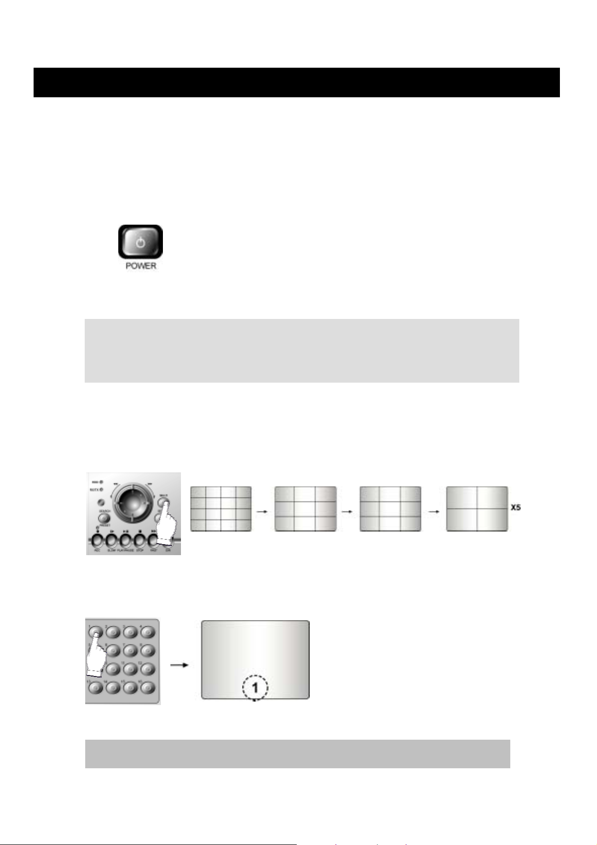
2-1. POWER ON / OFF
After the connection of power cord and other devices with SVR-1620, Turn the power on.
a. The video signal system (NTSC or PAL) is automatically
detected.
b. Power Failure Recovery
SVR-1620 automatically reverts back to programmed re cord
parameters upon power restoration.
c. If the power key is protected by password, the power on/off
cannot be executed before input the correct password.
(Refer to the Password Setup in the main menu)
• Before the power of SVR-1620 is on, check the input power currency in advance and select
the indication of power input (230V=180V~265V, 115V=90V~135VAC)at the rear-side of DVR
• If there is no video signal, the video signal system is set to NTSC. Do not input the PAL type video signal or it ma
cause SVR-1620 malfunction. In this case, turn off and on again.
2-2. SCREEN DISPLAY
2-2-1. Multi Display & Full Screen display
a. Multi display
To change a single camera display to the multi camera, press the Multi button.
b. Full screen display
Press the desired camera number button you wish to display on the monitor.
The number of the camera select buttons are used to set the password In the Password Lock function.
16
USER’S MANUAL
OPERATION
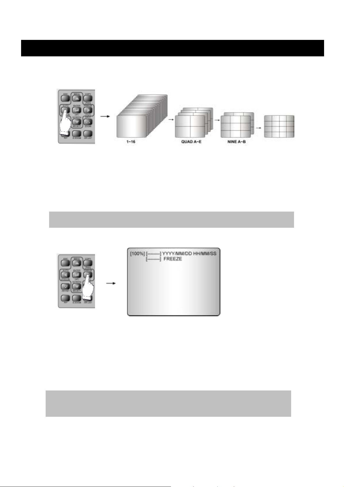
2-2-2. Auto Sequence Display
(ADD AUTO SINGLE : ON)
- Press the AUTO button, each screen displaying will be automatically switching according to
the Auto Sequence Setup. (Please refer to the Auto sequence setup in the main menu, p32)
- “ADD AUTO SINGLE : OFF” in the Auto sequence setup menu, the single display wil be
skipped.)
- Press the AUTO button again to escape from the AUTO mode.
- To view the single display, select “ADD AUTO SINGLE : ON” in the Auto sequence setup
menu and the single display will be included in the Auto Sequence Display.
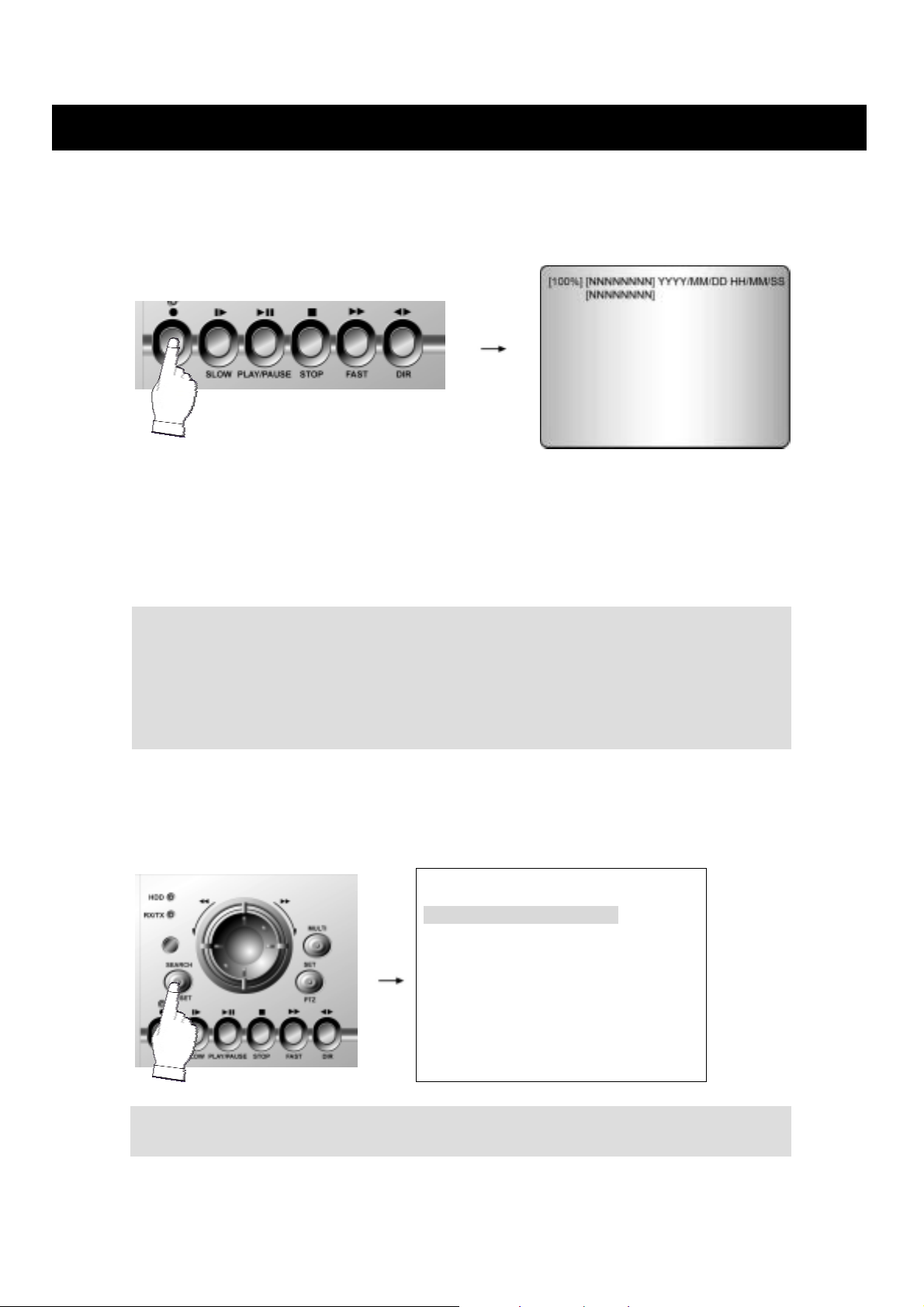
2-2-3. Freeze
MULTI SCREEN MODE
At the Multi display mode, Press the FREEZE button, and then select the desired camera
number.
Press the FREEZE button again to release the FREEZE mode.
SINGLE SCREEN MODE
Press the FREEZE button after the desired number of channel is selected..
Press the FREEZE button again to release the FREEZE mode.
Turn on the MULTI button after pressing the FREEZE button in the Multi SCREEN mode and all the channels will
display a freeze picture.
If an event takes place, the auto sequence mode will be cancelled.
DIGITAL VIDEO RECORDER
17
OPERATION
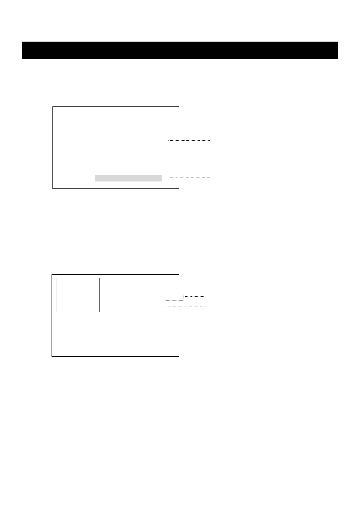
2-3. RECORD
Press the REC button, the following message will be displayed as below;
MANUAL MODE
Press the REC button to begin recording.
To stop recording, press the REC button again.
SCHEDULE MODE
When Schedule mode is selected, the recording will be automatically executed according to the
recording schedule. (Please refer to the Schedule setup in the main menu)
The record ENTER indication ( [NNNNNNNN]
recording and refer to the following. ( “N”,”E”,”S” : Recording, “
- “ N ” : Manual recording.
- “ S ” : Schedule recording.
- “ E ” : Event recording.(MD, V-LOSS, Sensor)
2-4. PLAYBACK
Press the SEARCH button, the Search menu screen appears.
If you press the PLAY button in the real time screen mode, playback will be executed from the
end of the previous time search and press the desired channel select button.
) on the screen will be changed according to the type of
-“ : Not Recording)
SEARCH>
FIXED-HDD TIME SEARCH
R-HDD TIME SEARCH
R-HDD EVENT LIST
LOG FILE LIST
18
USER’S MANUAL
OPERATION
2-4-1. FIXED-HDD TIME SEARCH
At the SEARCH menu;
① Turn the SHUTTLE ring to select the FIXED-HDD TIME SEARCH.
② Press ENTER button. The FIXED-HDD TIME SEARCH menu screen appears.
[FIXED-HDD TIME SEARCH]
HDD ID : ALL
CHANNEL: MULTISCREEN PLAY
STAR T TIME: YYYY/MM/DD HH:MM:SS
END TIME: YYYY/MM/DD HH:MM:SS
BOARD S/N:************
HDD S/N:
SEARCH TIME: YYYY/MM/DD HH:MM:SS
③ Select the desired search channel by using the JOG dial.
④ Turn the SHUTTLE ring to move the desired position of search time, and then turn the JOG
dial to set the search time.
⑤ Press the PLAY button for the Playback. To escape from the search menu, press the ESC
button.
2-4-2. FIXED-HDD EVENT LIST(ALARM LIST)
① Press the AR LIST button to select the FIXED-HDD EVENT LIST.
② The FIXED-HDD EVENT LIST menu screen appears.
[EVENT LIST]
CHANNEL : ALL
EVENT KIND : ALL
SEARCH
NO DATE TIME CH EVENT
③ Turn the SHUTTLE ring and JOG dial to select the desired channel and type of event.
④ Turn the SHUTTLE ring to select the SEARCH menu, and then press the ENTER button.
⑤ When the Event list appears on the screen, turn the JOG dial to select the desired list and
press the PLAY button to display the images.
⑥ Press the ESC button to exit the Event list.
③
④
③
④
DIGITAL VIDEO RECORDER
19
OPERATION
2-4-3. R-HDD TIME SEARCH
At the SEARCH menu;
① Turn the SHUTTLE ring to select the R-HDD TIME SEARCH.
② Press ENTER button. The R-HDD TIME SEARCH menu screen appears.
[R-HDD TIME SEARCH LIST]
[START TIME] [END TIME]
YYYY/MM/DD HH/MM/SS YYYY/MM/DD HH/MM/SS
----/--/-- --/--/-- ----/--/-- --/--/--
----/--/-- --/--/-- ----/--/-- --/--/--
----/--/-- --/--/-- ----/--/-- --/--/--
----/--/-- --/--/-- ----/--/-- --/--/--
----/--/-- --/--/-- ----/--/-- --/--/--
----/--/-- --/--/-- ----/--/-- --/--/--
----/--/-- --/--/-- ----/--/-- --/--/--
----/--/-- --/--/-- ----/--/-- --/--/--
----/--/-- --/--/-- ----/--/-- --/--/--
HDD ID : ALL
BOARD S/N : ************
HDD S/N :
[R-HDD TIME SEARCH]
CHANNEL : MULTISCREEN PLAY
STAR T TIME : YYYY/MM/DD HH:MM:SS
END TIME : YYYY/MM/DD HH:MM:SS
SEARCH TIME : YYYY/MM/DD HH:MM:SS
③ Turn the SHUTTLE ring to select one of the Search list, and then press the PLAY button for
the playback. Otherwise, press the ENT button to go to the detailed R-HDD time search.
④ Select the desired search channel by using the JOG dial
⑤ Turn the SHUTTLE ring to move the desired position of search time, and then turn the JOG
dial to set the search time.
⑥ Press the ENT button for the Playback. To escape from the search menu, press the ESC
button.
Please refer to the Event Record Backup in the main menu.
2-4-4. R-HDD EVENT LIST
At the SEARCH menu;
① Turn the SHUTTLE ring to select the R-HDD EVENT LIST.
② Press the ENTER button. The R-HDD EVENT LIST menu screen appears.
[BACKUP EVENT LIST]
CHANNEL : ALL
EVENT KIND : ALL
SEARCH
NO DATE TIME CH EVENT
③ Turn the SHUTTLE ring and JOG dial to select the desired channel and type of event.
④ Turn the SHUTTLE ring to select the SEARCH menu, and then press the ENTER button.
⑤ When the Event list appears on the screen, turn the JOG dial to select the desired list and
press the PLAY button to display the images.
⑥ Press the ESC button to exit the menu.
20
USER’S MANUAL

OPERATION
2-4-5. LOG FILE LIST
At the SEARCH menu;
① Turn the SHUTTLE ring to select the LOG FILE LIST.
② Press the ENTER button. The LOG FILE LIST menu screen appears.
[LOG FILE LIST]
NO DATE TIME CONTENTS
1 YYYY/MM/DD HH:MM:SS PRG UPDATE
2 YYYY/MM/DD HH:MM:SS POWER ON
3 YYYY/MM/DD HH:MM:SS SETUP UPDATE
4 YYYY/MM/DD HH:MM:SS REC END
5 YYYY/MM/DD HH:MM:SS REC END
6 YYYY/MM/DD HH:MM:SS REC END
③ Turn the JOG dial to or press the +, - button to search the log file list.
④ To escape from the log file list, press the ESC button.
- When video loss is detected, up to five seconds of pre-recording data is stored on the HDD and the details will be
listed in the EVENT LIST.
- When the unit receives a signal from the sensor input, DVR begins to record the input data according to the
RECORD TIME in the EVENT SETUP and the details will be listed in the EVENT LIST.
CAUTION
a
If the internal HDD(s) is initialized, all of the event images will be deleted.
○
b
When the unit is in normal recording status, the pre-recording will not be executed.
○
DIGITAL VIDEO RECORDER
21
 Loading...