

Page 1

NETWORK CAMERA
User Manual
SNP-5300/SNP-5300H
Page 2

Network Camera
User Manual
Copyright
©2013 Samsung Techwin Co., Ltd. All rights reserved.
Trademark
The name of thi s product is the reg istered tradema rk of Samsung Techwin C o., Ltd.
Other trad emarks mention ed in this manual are th e registered trad emark of their resp ective company.
Restriction
Samsung Techwi n Co., Ltd shall reser ve the copyrigh t of this document. U nder no circumst ances, this docu ment shall
be reproduced, distributed or changed, partially or wholly, without formal authorization of Samsung Techwin.
Disclaimer
Samsung Techwi n makes the best to ver ify the integri ty and correct ness of the conten ts in this document , but no
formal guar antee shall be provi ded. Use of this do cument and the subse quent results sha ll be entirely on the u ser’s own
responsib ility. Samsung Techwi n reserves the ri ght to change the con tents of this docum ent without prio r notice.
Design and specifications are subject to change without prior notice.
The defau lt password c an be exposed to a h acking thread s o it is recommen ded to change th e password
after in stalling the pr oduct.
Note that t he security a nd other relat ed issues caus ed by the unchan ged password s hall be respon sible
for the use r.
is the regist ered logo of Samsun g Techwin Co., Ltd.
Page 3
overview
IMPORTANT SAFETY INSTRUCTIONS
1. Read these instructions.
2. Keep these instructions.
3. Heed all warnings.
4. Follow all instructions.
5. Do not use this apparatus near water.
6. Clean only with dry cloth.
7. Do not block any ventilation openings, Install in accordance with the manufacturer’s
instructions.
8. Do not install near any heat sources such as radiators, heat registers, stoves, or other
apparatus (including amplifiers) that produce heat.
9. Do not defeat the safety purpose of the polarized or grounding-type plug. A polarized
plug has two blades with one wider than the other. A grounding type plug has two
blades and a third grounding prong. The wide blade or the third prong are provided for
your safety. If the provided plug does not fit into your outlet, consult an electrician for
replacement of the obsolete outlet.
10. Protect the power cord from being walked on or pinched particularly at plugs,
convenience receptacles, and the point where they exit from the apparatus.
11. Only use attachments/ accessories specified by the manufacturer.
12. Use only with the cart, stand, tripod, bracket, or table specified by
the manufacturer, or sold with the apparatus. When a cart is used,
use caution when moving the cart/apparatus combination to avoid
injury from tip-over.
13. Unplug this apparatus during lighting storms or when unused for
long periods of time.
14. Refer all servicing to qualified service personnel. Servicing is required when the
apparatus has been damaged in any way, such as power-supply cord or plug is
damaged, liquid has been spilled or objects have fallen into the apparatus, the apparatus
has been exposed to rain or moisture, does not operate normally, or has been dropped.
● OVERVIEW
English _3
Page 4
overview
WARNING
TO REDUCE THE RISK OF FIRE OR ELECTRIC SHOCK, DO NOT EXPOSE
THIS PRODUCT TO RAIN OR MOISTURE. DO NOT INSERT ANY METALLIC
OBJECT THROUGH THE VENTILATION GRILLS OR OTHER OPENNINGS
ON THE EQUIPMENT.
Apparatus shall not be exposed to dripping or splashing and that no objects
filled with liquids, such as vases, shall be placed on the apparatus.
To prevent injury, this apparatus must be securely attached to the Wall/ceiling
in accordance with the installation instructions.
CAUTION
CAUTION
RISK OF ELECTRIC SHOCK.
DO NOT OPEN
CAUTION
REFER SERVICING TO QUALIFIED SERVICE PERSONNEL.
: TO REDUCE THE RISK OF ELECTRIC SHOCK.
DO NOT REMOVE COVER (OR BACK).
NO USER SERVICEABLE PARTS INSIDE.
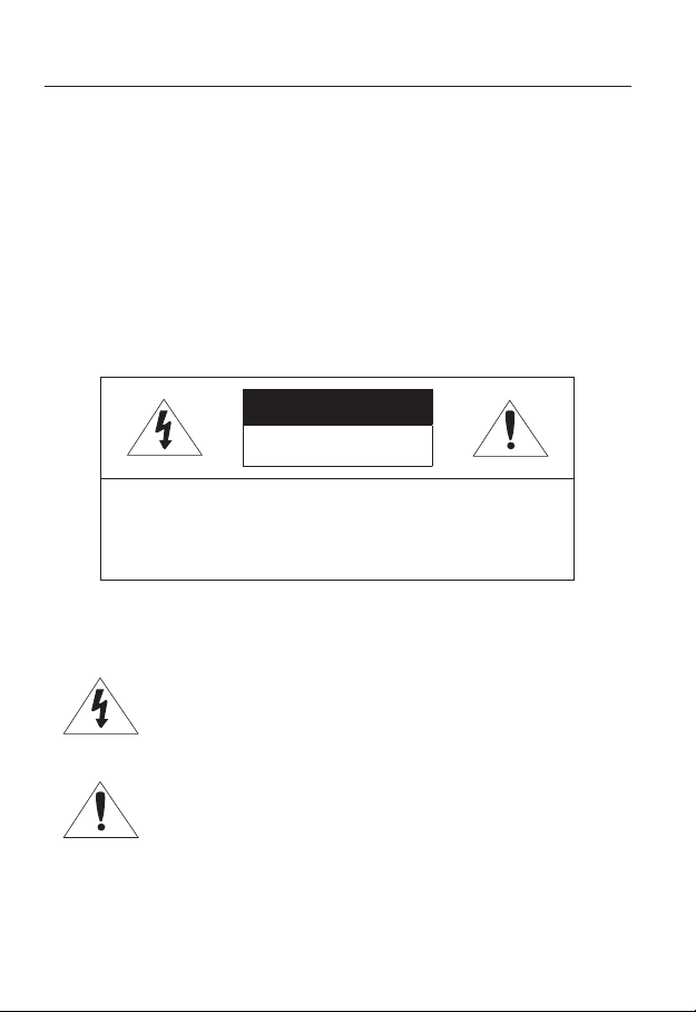
EXPLANATION OF GRAPHICAL SYMBOLS
The lightning flash with arrowhead symbol, within an
equilateral triangle, is intended to alert the user to the
presence of “dangerous voltage” within the product’s
enclosure that may be of sufficient magnitude to constitute a
risk of electric shock to persons.
The exclamation point within an equilateral triangle is intended
to alert the user to the presence of important operating
and maintenance (servicing) instructions in the literature
accompanying the product.
4_ overview
Page 5

Battery
Batteries(battery pack or batteries installed) shall not be exposed to excessive
heat such as sunshine, fire or the like.
CAUTION
Risk of explosion if battery is replaced by an incorrect type.
Dispose of used batteries according to the instructions.
These servicing instructions are for use by qualified service personnel only.
To reduce the risk of electric shock do not perform any servicing other than
that contained in the operating instructions unless you are qualified to do so.
Please use the input power with just one camera and other devices must not
be connected.
The ITE is to be connected only to PoE networks without routing to the
outside plant.
● OVERVIEW
English _5
Page 6

overview
Please read the following recommend safety precautions carefully.
yDo not place this apparatus on an uneven surface.
yDo not place this apparatus near conductive material.
yDo not attempt to service this apparatus yourself.
yDo not install near any magnetic sources.
yDo not block any ventilation openings.
yDo not place heavy items on the product.
yDo not expose the camera to radioactivity.
User’s Manual is a guidance book for how to use the products.
The meaning of the symbols are shown below.
yReference : In case of providing information for helping of product’s usages
yNotice : If there’s any possibility to occur any damages for the goods and
human caused by not following the instruction
Please read this manual for the safety before using of goods and keep it in
the safe place.
6_ overview
Page 7

CONTENTS
OVERVIEW
3
INSTALLATION &
CONNECTION
18
NETWORK CONNECTION
AND SETUP
34
3 Important Safety Instructions
9 Product Features
10 Recomended PC Specifications
10 Recomended SD/SDHC Memory
Card Specifications
11 What’s Included
13 At a Glance (SNP-5300)
15 At a Glance (SNP-5300H)
19 Connecting with other Device
21 Installation
32 Inserting/Removing a SD Memory
Card
33 Memory Card Information
(Not Included)
34 Connecting the Camera Directly
to Local Area Networking
35 Connecting the Camera Directly
to a DHCP Based DSL/Cable
Modem
36 Connecting the Camera Directly
to a PPPoE Modem
37 Connecting the Camera to a
Broadband Router with the
PPPoE/Cable Modem
38 Buttons used in IP Installer
39 Static IP Setup
43 Dynamic IP Setup
44 Port Range Forward (Port
Mapping) Setup
46 Connecting to the Camera from a
Shared Local PC
46 Connecting to the Camera from a
Remote PC via the Internet
● OVERVIEW
English _7
Page 8

overview
WEB VIEWER
47
SETUP SCREEN
61
APPENDIX
108
47 Connecting to the Camera
48 Login
49 Installing ActiveX
50 Installing Silverlight Runtime
52 Using the Live Screen
56 Playing the recorded video
61 Setup
61 Audio & Video Setup
80 Network Setup
89 Event Setup
102 System Setup
108 Specification
113 Product Overview
115 Troubleshooting
117 Open source license notification
on the product
8_ overview
Page 9

PRODUCT FEATURES
• Full HD Video Quality
• Multi-Streaming
This network camera can display videos in different resolutions and qualities
simultaneously using different CODECs.
• Web Browser-based Monitoring
Using the Internet web browser to display the image in a local network environment.
• Alarm
If an event occurs, the event-related video will be transferred to the FTP/email specified
by the user or saved to the SD memory, or the event signal will be sent to the Alarm Out
port.
• Tampering Detection
Detects tempering attempts on video monitoring.
• Motion Detection
Detects motion from the camera’s video input.
• Intelligent Video Analysis
Analyzes video to detect logical events of specified conditions from the camera’s video
input.
• Face Detection
Detects faces from the camera’s video input.
• Audio Detection
Detects sound louder than a certain level specified by user.
• Auto Detection of Disconnected Network
Detects network disconnection before triggering an event.
• ONVIF Compliance
This product supports ONVIF.
For more information, refer to www.onvif.org.
● OVERVIEW
English _9
Page 10

overview
RECOMENDED PC SPECIFICATIONS
• CPU : Intel Core 2 Duo 2.6GHz or higher
• Operating System : Microsoft Windows 7/VISTA/XP SP3, Apple MAC OS
• Resolution : 1280X1024 pixels or higher
• RAM : 2GB or higher
• Web Browser : Firefox, Google Chrome, *Apple Safari, Windows Internet Explorer 9.0
(32bit)/8.0(32bit)/7.0(32bit)
Neither a beta test version unlike the version released in the company website nor the developer version will
`
be supported.
It is recommended to connect to IPv6 in Windows 7.
`
For Mac OSX, only the Safari browser is supported.
`
• Video Memory : 256MB or higher
If the driver of the video graphic adapter is not installed properly or is not the latest version, the
`
J
video may not be played properly.
For a multi-monitoring system involving at least 2 monitors, the playback performance can be
`
deteriorated depending on the system.
It is advisable to use Intel Core 2 Duo 2.93GHz or higher in a multi-browser environment.
`
RECOMENDED SD/SDHC MEMORY CARD SPECIFICATIONS
• 4GB ~ 32GB
• For your camera, we recommend you use a memory card from the following
manufacturers:
SD/SDHC Memory Card : Sandisk, Transcend
• It is recommended to use memory cards of at least class 6 speed.
10_ overview
Page 11
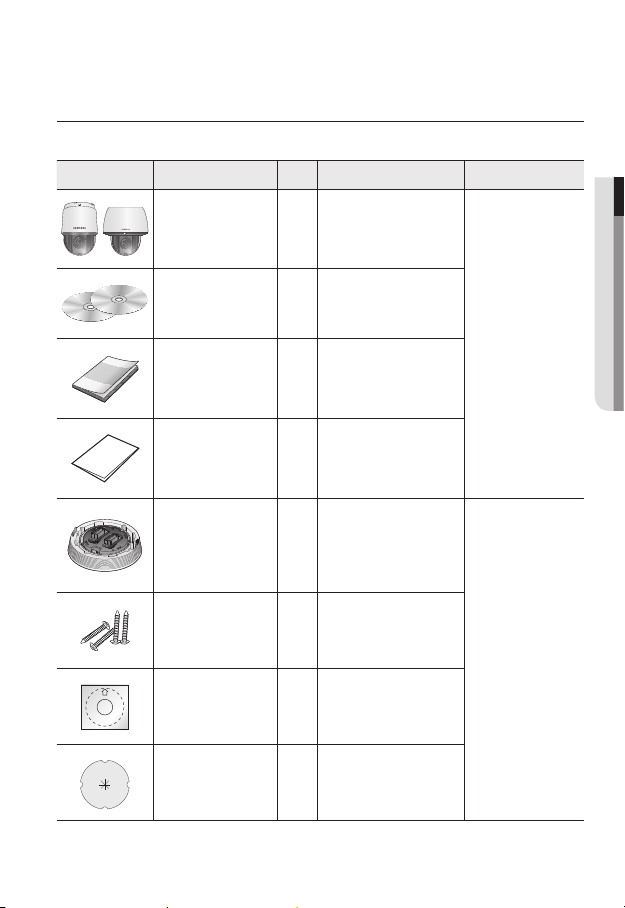
WHAT’S INCLUDED
Please check if your camera and accessories are all included in the product package.
Appearance Item Name
Camera 1
Instruction book,
Installer S/W CD,
CMS S/W DVD
Quick Guide
(Optional)
Quantity
2
1
Description Model Name
SNP-5300 or
SNP-5300H
● OVERVIEW
Warranty card
(Optional)
Installation base 1
Tapping Screw 4
Template 1 Product installation guide
Insulation Sheet 1
1
If installing it indoors or in a
ceiling housing
Used for installation on the
ceiling
Use when installing the camera
at highly humid place
SNP-5300
English _11
Page 12
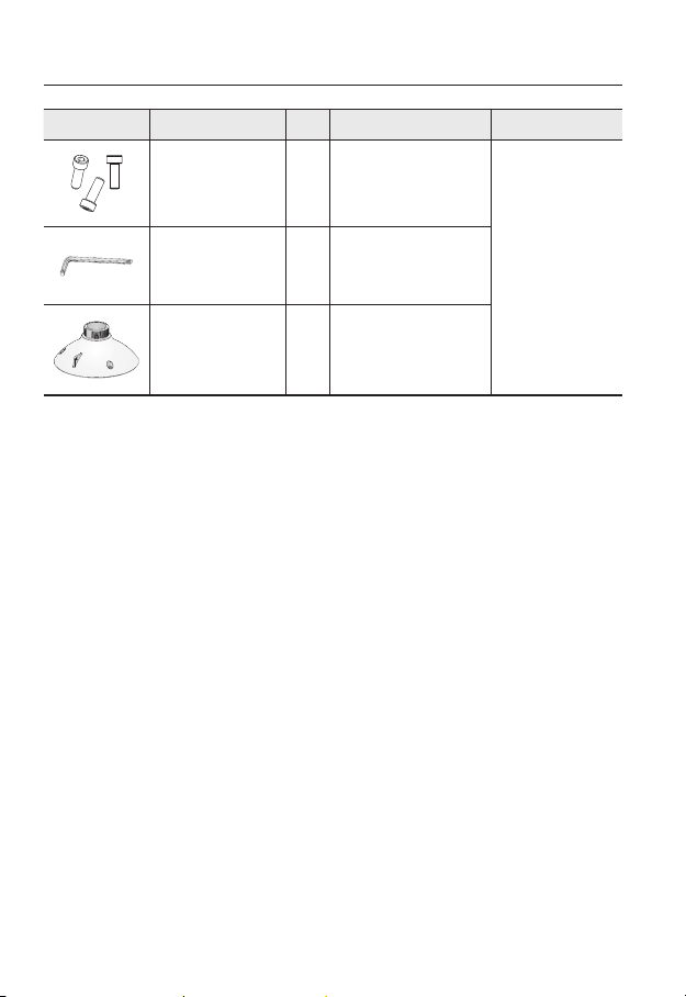
overview
Appearance Item Name
Hexagon screw 3
L Wrench 1
Installation base 1 Bracket for mounting outdoors
Quantity
Description Model Name
Used for attaching the
installation base to the camera
Used for fixing the installation
base after attaching it to the
camera
SNP-5300H
12_ overview
Page 13
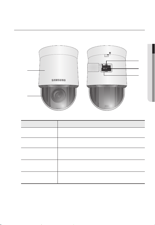
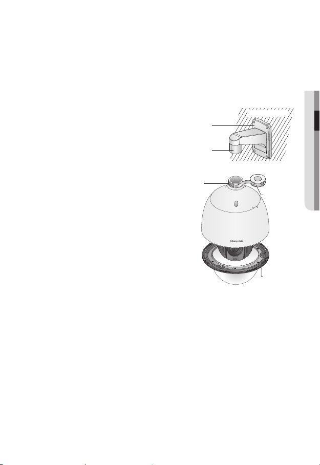
AT A GLANCE (SNP-5300)
Appearance
a
b
Item Description
Main unit Protect the internal PTZ mechanism from the direct sunlight.
a
Dome Cover Dome cover for the lens and unit protection.
b
SD Memory Card
c
Compartment
After Service Port
d
(A/S port)
Reset Button
e
Compartment for the SD memory card.
This is for the repair purpose only that is not available for the user.
Pressing and holding this button for about 5 seconds will reset all camera
settings to the factory default.
● OVERVIEW
c
d
e
English _13
Page 14
overview
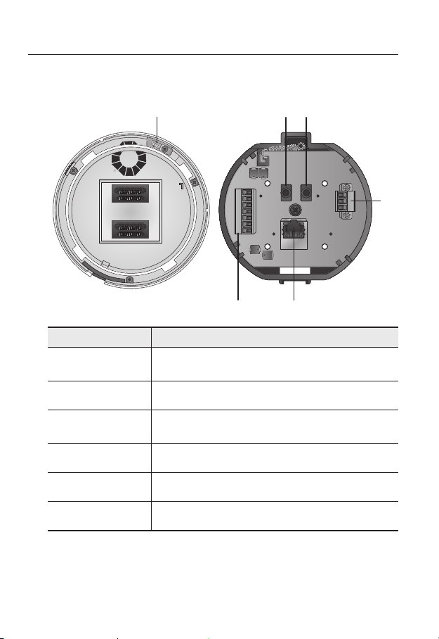
Bottom View of Installation
Base
Item Description
Safety Cable
a
Connection Ring
Alarm I/O Port Used to connect the alarm I/O cable.
b
Network
c
Connections
Power Port Used to connect the power.
d
Connect the cable to prevent the product from dropping during installation to
the ring.
Used to connect a PoE+ or LAN cable.
Inner View of Installation Base
ea
f
b
OUT1OUT2
GND
IN1 IN2 IN3 IN4
c
AUDIOIN
AUDIOOUT-L
d
Audio Output Port Used to connect the audio output cable.
e
Audio Input Port Used to connect the audio input cable.
f
14_ overview
Page 15
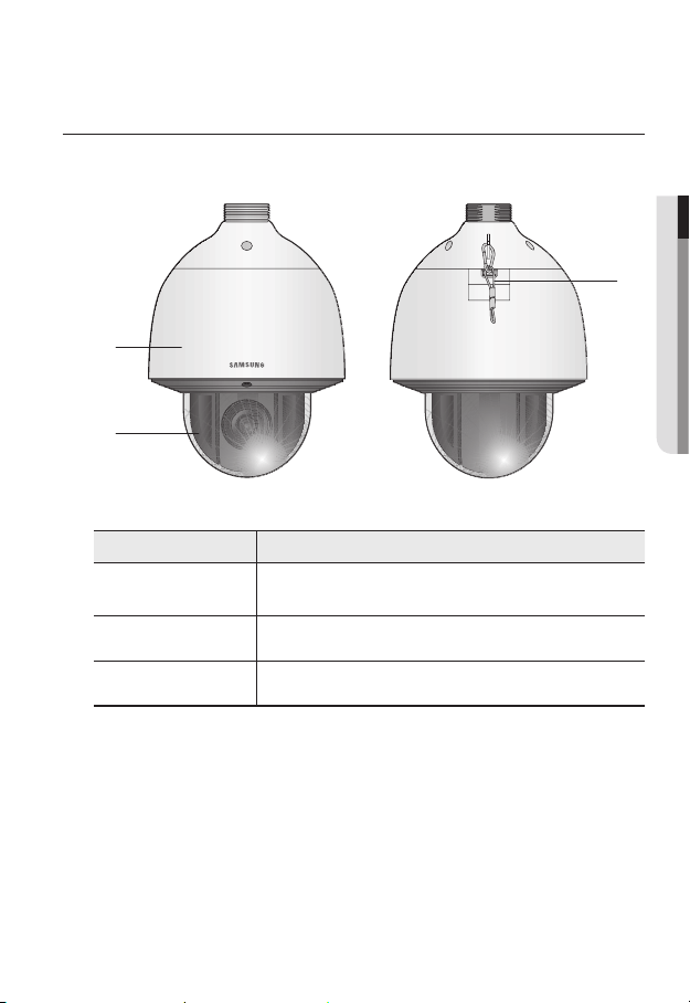
AT A GLANCE (SNP-5300H)
Appearance
a
b
Item Description
Main unit
a
Dome Cover Dome cover for the lens and unit protection.
b
Safety Cable The cable prevents the product from dropping during installation.
c
Protects the internal PTZ mechanism from the direct sunlight, rain or
external impact.
● OVERVIEW
c
English _15
Page 16
overview
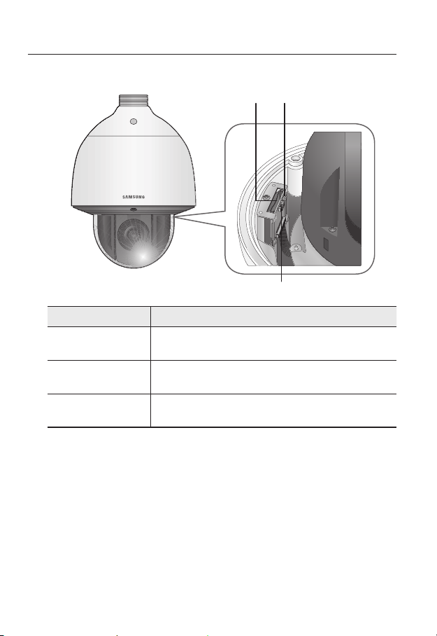
Inside
Item Description
SD Memory Card
a
Compartment
Reset Button
b
After Service Port
c
(A/S port)
a
b
c
Compartment for the SD memory card.
Pressing and holding this button for about 5 seconds will reset all camera
settings to the factory default.
This is for the repair purpose only that is not available for the user.
16_ overview
Page 17
Bottom View of Installation
Base
a e
Inner View of Installation Base
f
● OVERVIEW
Item Description
Safety Cable
a
Connection Ring
Alarm I/O Port Used to connect the alarm I/O cable.
b
Network
c
Connections
Power Port Used to connect the power.
d
Audio Output Port Used to connect the audio output cable.
e
Audio Input Port Used to connect the audio input cable.
f
Connect the cable to prevent the product from dropping during installation to
the ring.
Used to connect a PoE+ or LAN cable.
b
OUT1OUT2
GND
IN1 IN2 IN3 IN4
AUDIOIN
AUDIOOUT-L
d
c
English _17
Page 18
installation & connection
`Camera Wiring Interface Board
For the camera wiring, please refer to the picture below.
Audio INAudio
OUT
Power Supply
Alarm
AUDIOIN
Alarm Input
Sensor
AUDIOOUT-L
ETHERNET
Camera’s
internal
GND
AC24V 2.5A
3.3V
OUT1OUT2
GND
IN1 IN2 IN3 IN4
Select Normal Open in the setup menu.
`
J
The sensor input is activated during a short for contact type, or when it is at “Low” level for
-
the active type.
Select Normal Close from the Setup menu.
`
The sensor input is activated when open for the contact type or when in high impedance
-
state (open collector) for the active type.
The maximum power capacity of the alarm outputs is DC +40V and 80 mA.
`
When connecting alarm input and output cables, be sure to connect one cable to each
`
terminal respectively.
To connect products over the camera’s capacity, please use an additional relay device.
`
Connecting the power connector and GND incorrectly to the alarm out port may lead to fire
`
and damage the camera.
Power Input
Ground
Sensor
input
18_ installation & connection
Page 19
CONNECTING WITH OTHER DEVICE
Preparing Adapter and Cable
Connect the camera to the power adaptor. Then, plug the power cord of the adaptor to the wall
`
J
outlet.
IN1 IN2IN3 IN4
GND
OUT1OUT2
AUDIOIN
AUDIOOUT-L
Check out the rated voltage and current before making connections.
Rated Power Allowable Input Voltage Current Consumption
AC 24V AC 22V ~ 26V 2.5 A
If applied with both PoE+ and AC 24V power supplies, the device is powered from the first
`
J
engaged supply.
It is preferred to use single power supply of either one of PoE+ and AC 24V.
-
If connected to a switch device that provides PoE+ power, you don’t need to apply a power source
`
of AC 24V supply.
Make sure the PoE device suffices PoE+ (IEEE 802.3at) specifications.
`
If connecting to the PoE device of IEEE 802.3af standard, set the ‘Do not use PoE’ of the switch
-
device.
For further information on switch device, refer to the manufacturer’s manual.
The PoE switch model (for each channel) and PoE connection time can differ according to the
`
manufacturer.
● INSTALLATION & CONNECTION
English _19
Page 20

installation & connection
Electrical Resistance of Copper Wire at [20°C (68°F)]
Copper Wire Gauge (AWG) #24(0.22mm2) #22(0.33mm2) #20(0.52mm2) #18(0.83mm2)
Resistance (Ω/m) 0.078 0.050 0.030 0.018
Drop Voltage (V/m) 0.028 0.018 0.011 0.006
Recommended Distance (m) Less than 20 Less than 30 Less than 30 Less than 30
As shown in the table above, you may encounter a voltage-sag depending on the wire length.
`
If you use an excessively long wire for camera connection, the camera may not work properly.
Camera Operating Voltage: AC 24V±10%
-
Voltage drop measurements on the chart above may vary depending on the type and manufacture of
-
the copper cable.
Ethernet Connection
Connect the Ethernet cable to the local network or to the Internet.
20_ installation & connection
Page 21

INSTALLATION
Preparing & Installing Camera Bracket
For installation guidelines for brackets and housings, refer to the installation manual that is
enclosed with the bracket or housing.
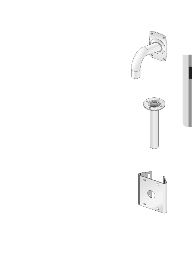
`Available Bracket Models
Model Item SNP-5300 SNP-5300H
SHP-3701H Outdoor Housing
-SHP-3701F Ceiling-mount Housing
SBP-300HM3 Hanging Mount
SBP-300WM1
SBP-300WM
SBP-300CM Ceiling Mount
SBP-300LM Parapet Mount
SBP-300KM Corner Mount
SBP-300PM Pole Mount
See “Optional Accessories for Installation” for the appearance of each bracket (unbundled).
`
M
(page 28)
Wall Mount
Yes
Yes
● INSTALLATION & CONNECTION
English _21
Page 22
installation & connection
Installing by surface attachment
SNP-5300H cannot be installed on the surface of a wall or ceiling.
`
M
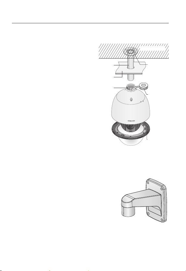
`Attaching Template & Installing installation base
1. Attach the provided template on the ceiling. Based on the template, drill a 86mm
hole in the ceiling and arrange the wires through the hole.
2. Install installation base as shown.
3. Before installing the exposed bracket, open the hinged door at the bottom of the
bracket as shown in the picture. Hold the knob on the hinged door to open it.
In the case of installing the camera at highly humid place, install it on the ceiling after attaching
`
J
the enclosed insulation sheet on the back of install base.
Template
22_ installation & connection
Insulation Sheet
<Attaching insulatioin sheet>
Page 23
`Connect Terminal Wires
1. Connect the cables to the terminal block on the
hinged door. Refer to “Camera Wiring Interface
Board”. (page 18)
2. Once the wiring is complete, close the hinged
door.
Do not connect the camera to a power outlet until the
`
J
installation is complete. Supplying power while the
installation is in progress may cause fire or damage the
product.
`Connecting Camera Safety Cable and Attaching Camera
1. First, as shown in the left hand picture, pull out the safety cable from the base and
then hook it to the mount. The safety cable is coiled inside the base.
To attach the camera to the mount, refer to the alignment guide marks as shown in the picture.
`
2. Carefully attach the camera to the mount following the alignment guide marks as
shown in the picture.
Direction
Guides
Direction
Guides
Align the Direction
Guides
● INSTALLATION & CONNECTION
Make sure to hook the camera’s safety cable to the mount before proceeding. Otherwise you may
`
J
be exposed to serious injury caused by the camera falling.
English _23
Page 24
installation & connection
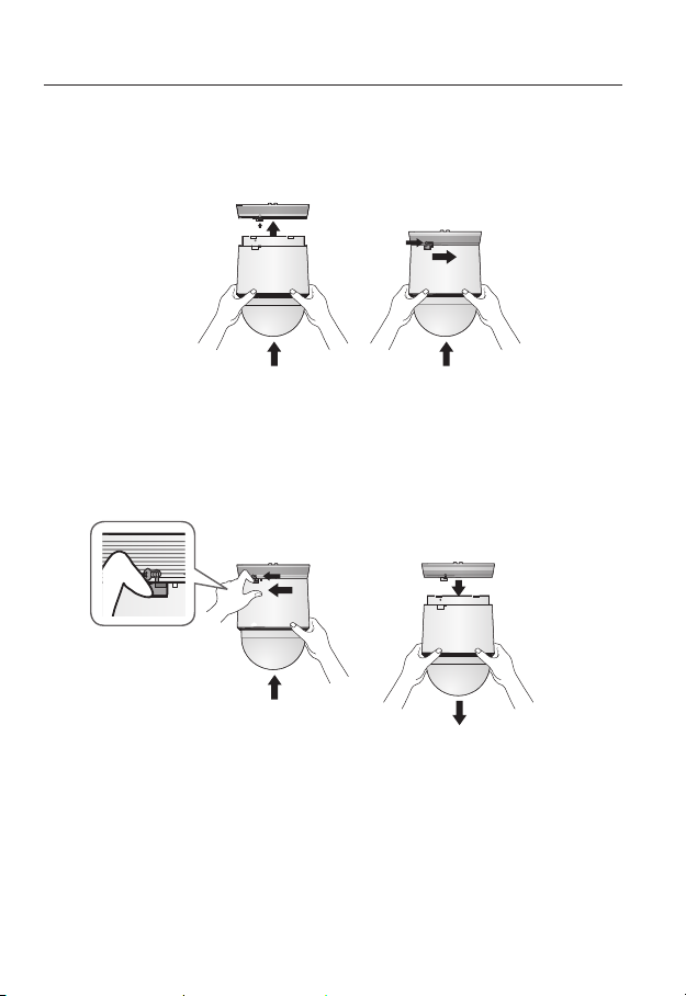
- To attach or detach the camera, refer to the picture.
• Attaching the Camera : Push up the camera unit and rotate it clockwise until
it cannot be rotated anymore, as shown in the figure. After rotation, fasten the
screws assembled to the install base.
< To Attach the Camera >
• Detaching the Camera : Unfasten the screws as shown in the figure, push in the
hook, and rotate it counterclockwise.
(The screws are not completely disassembled.)
When the hook does not rotate any more, pull down the camera unit and
separate it.
24_ installation & connection
< To Detach the Camera >
Page 25
Installing by wall mount
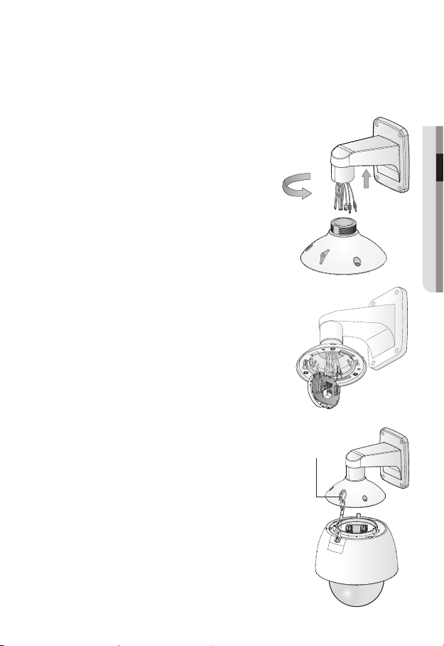
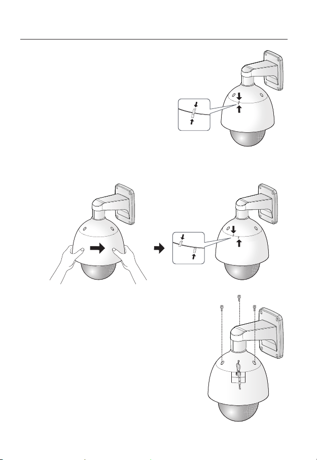
`Fix the installation base with the bracket
1. Fix the base with the bracket by turning it
clockwise.
2. As shown in the picture below, gently press and lift
up the handle of the hinged door on the bottom of
the installation base. Please refer to the “Camera
Wiring Interface Board” on page 18, connect the
wires.
Do not connect the camera to a power outlet until the
`
J
installation is complete. Supplying power while the
installation is in progress may cause fire or damage the
product.
3. Connect the camera safety wire to the installation base.
● INSTALLATION & CONNECTION
Safety Cable
English _25
Page 26
installation & connection
4. Assemble Camera and Installation Base
Assemble the installation base and camera
by matching the installation direction guides.
5. Attach Camera
Rotate the mounted camera unit clockwise so that the reference indicators of top
and bottom are as shown in the image on the right.
6. Secure Camera and Installation Base
As shown in the picture below, secure
the installation base and camera using 3
hexagon screws.
26_ installation & connection
Page 27
Notes for Waterproofing
This product is an indoor unit. If it is installed outdoors, use the outdoor housing to make it
waterproof.
`Installing the unit on the wall by combining the outdoor housing and wall
mount
1. Install the wall mount on the vertical wall.
If the mount is installed on an inclined
wall, moisture can penetrate inside the
outdoor housing through the external
cable.
2. Wrap the screw part of the housing with
a sufficient amount of Teflon tape for
assembly.
3. When separating the dome cover and
fastening it to the housing frame, make
sure that the gasket is not loosened to
separate from the dome cover.
4. Install the wall mount adapter for
waterproofing, and apply the silicon
sealant between and around the wall and
wall mount for sealing.
Take particular caution to ensure that there
`
J
is proper sealing if the installed side is not
flat.
Silicon
sealant
Wall mount
Screw
unit
Concrete wall
Teflon tape
Dome gasket
● INSTALLATION & CONNECTION
English _27
Page 28
installation & connection
`Installing on the wall by combining the outdoor housing and ceiling mount
adapter
1. Wrap the screw part of the housing
with a sufficient amount of Teflon tape
for assembly.
2. When separating the dome cover and
fastening it to the housing frame, make
sure that the gasket is not loosened to
separate from the dome cover.
3. Install the ceiling mount adapter for
waterproofing, and apply the silicon
sealant between and around the wall
and ceiling mount for sealing.
Take particular caution to ensure that
`
J
there is proper sealing if the installed side
is not flat.
Ceiling mount
adapter
Ceiling board
Screw
unit
Optional Accessories for Installation
For your easier installation, you can purchase appropriate optional accessories available.
1. If installing the camera on the wall
• Wall mount (SBP-300WM1)
Concrete ceiling
Silicon
sealant
Teflon tape
Dome gasket
28_ installation & connection
Page 29
• Wall mount (SBP-300WM)
2. If installing the camera on the ceiling
• Ceiling Mount (SBP-300CM)
3. If installing the wall mount (SBP-300WM/SBP-300WM1) on an at least 80mm-long
cylinder
• Pole Mount (SBP-300PM)
● INSTALLATION & CONNECTION
English _29
Page 30
installation & connection
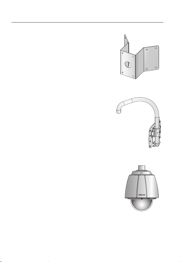
4. If installing the wall mount (SBP-300WM/SBP-300WM1) on a corner of the wall
• Corner Mount (SBP-300KM)
5. If installing on a building rooftop
• Parapet Mount (SBP-300LM)
6. If installing SNP-5300 outdoors
• Outdoor Housing (SHP-3701H)
30_ installation & connection
Page 31

7. If installing SNP-5300 on a ceiling as built-in component
• Flush-Mount Indoor Housing for PTZ Dome Camera
(SHP-3701F)
8. If installing SNP-5300 in the wall mount or ceiling mount
• Hanging Mount (SBP-300HM3)
● INSTALLATION & CONNECTION
English _31
Page 32

installation & connection
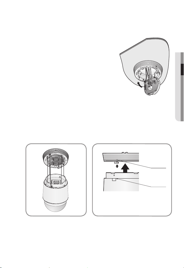
INSERTING/REMOVING A SD MEMORY CARD
Disconnect the power cable from the camera before inserting the SD memory card.
`
J
Inserting a SD Memory Card
1. Open the cover in the rear of the camera.
(SNP-5300)
Using the screw driver, loosen 3 screws by turning
them counterclockwise and separate the dome cover.
(SNP-5300H)
2. Push the SD memory card in the direction of the
arrow shown in the diagram.
Do not insert the SD memory card while it’s upside down
`
J
by force. Otherwise, it may damage the SD memory card.
32_ installation & connection
Page 33

Removing a SD Memory Card
Gently press down on the exposed end of the memory
card as shown in the diagram to eject the memory card
from the slot.
Pressing too hard on the SD memory card can cause
`
J
the card to shoot out uncontrollably from the slot when
released.
To turn off the camera or remove the SD memory card,
`
set <Record> to <Off> from <SD record> and press
[Apply (
If you turn off the camera or remove the SD memory card that contains data from the product, the
`
data may be lost or damaged.
)]. (page 90)
MEMORY CARD INFORMATION (NOT INCLUDED)
What is a memory card?
The memory card is an external data storage device that has been developed to offer an
entirely new way to record and share video, audio, and text data using digital devices.
Selecting a memory card that’s suitable for you
Your camera supports SD/SDHC memory cards.
You may, however, experience compatibility issues depending on the model and make of
the memory card.
For your camera, we recommend you use a memory card from the following
manufacturers:
SD/SDHC Memory Card : Sandisk, Transcend
Memory cards of 4GB ~ 32GB is recommended for using with this camera.
Playback performance can be affected depending on the speed of memory card, so use
the high-speed memory card.
It is recommended to use memory cards of at least class 6 speed.
● INSTALLATION & CONNECTION
Memory Card Use
SD and SDHC memory cards feature a switch that disables writing data on to the media.
Having this switch to the Lock position will prevent accidental deletion of data stored in the
memory card but at the same time will also prevent you from writing data on to the media.
English _33
Page 34

network connection and setup
You can set up the network settings according to your network configurations.
CONNECTING THE CAMERA DIRECTLY TO LOCAL AREA
NETWORKING
Connecting to the camera from a local PC in the LAN
1. Launch an Internet browser on the local PC.
2. Enter the IP address of the camera in the address bar of the browser.
Camera
Camera
Local PC
<Local Network>
A remote PC in an external Internet out of the LAN network may not be able to connect to the
`
M
camera installed in the intranet if the port-forwarding is not properly set or a firewall is set.
In this case, to resolve the problem, contact your network administrator.
By factory default, the IP address will be assigned from the DHCP server automatically.
`
If there is no DHCP server available, the IP address will be set to 192.168.1.100.
To change the IP address, use the IP Installer.
For further details on IP Installer use, refer to “Static IP Setup”. (Page 39)
34_ network connection and setup
Switch
Firewall
INTERNET
External Remote PC
DDNS Server
(Data Center, KOREA)
Page 35

CONNECTING THE CAMERA DIRECTLY TO A DHCP
BASED DSL/CABLE MODEM
INTERNET
DDNS Server
(Data Center, KOREA)
External Remote PC
Camera
DSL/Cable
Modem
1. Use the cross LAN cable to connect the network cable directly to your PC.
2. Run the IP Installer and change the IP address of the camera so that you can use
the web browser on your desktop to connect to the Internet.
3. Use the Internet browser to connect to the web viewer.
4. Move to [Setup] page.
5. Move to [Network] – [DDNS] and configure the DDNS settings.
6. Move to [Network] – [Interface], and set the network type to [DHCP].
7. Connect the camera, which was removed from your PC, directly to the modem.
8. Restart the camera.
For registering the DDNS settings, refer to “Registering with DDNS”. (page 83)
`
M
For configuring the DDNS settings, refer to “DDNS”. (page 82)
`
For setting the network type, refer to “Interface”. (page 80)
`
●
NETWORK CONNECTION AND SETUP
English _35
Page 36

network connection and setup
CONNECTING THE CAMERA DIRECTLY TO A PPPoE
MODEM
PPPoE Modem
Camera
1. Use the cross LAN cable to connect the network cable directly to your PC.
2. Run the IP Installer and change the IP address of the camera so that you can use
the web browser on your desktop to connect to the Internet.
3. Use the Internet browser to connect to the web viewer.
4. Move to [Setup] page.
5. Move to [Network] – [DDNS] and configure the DDNS settings.
6. Move to [Network] – [Interface], and set the network type to [PPPoE].
7. Connect the camera, which was removed from your PC, directly to the modem.
8. Restart the camera.
For registering the DDNS settings, refer to “Registering with DDNS”. (page 83)
`
M
For configuring the DDNS settings, refer to “DDNS”. (page 82)
`
For setting the network type, refer to “Interface”. (page 80)
`
INTERNET
DDNS Server
(Data Center, KOREA)
External Remote PC
36_ network connection and setup
Page 37

CONNECTING THE CAMERA TO A BROADBAND ROUTER
WITH THE PPPoE/CABLE MODEM
This is for a small network environment such as homes, SOHO and ordinary shops.
Camera
●
NETWORK CONNECTION AND SETUP
INTERNET
PPPoE or
Cable Modem
DDNS Server
(Data Center, KOREA)
External Remote
PC
Camera
Local PC
Broadband
Router
PPPoE or
Cable Modem
Configuring the network settings of the local PC connected to a
Broadband Router
Configuring the network settings of the local PC connected to a Broadband Router, follow
the instructions below.
• Select : <Network Neighborhood> <Properties> <Local Area Connection>
<Properties> <General> <Internet Protocol (TCP/IP)> <Properties>
<Obtain an IP address automatically> or <Use the following IP address>.
• Follow the instructions below if you select <Use the following IP address>:
ex1) If the address (LAN IP) of the Broadband Router is 192.168.1.1
IP address : 192.168.1.100
Subnet Mask : 255.255.255.0
Default Gateway : 192.168.1.1
ex2) If the address (LAN IP) of the Broadband Router is 192.168.0.1
IP address : 192.168.0.100
Subnet Mask : 255.255.255.0
Default Gateway : 192.168.0.1
ex3) If the address (LAN IP) of the Broadband Router is 192.168.xxx.1
IP address : 192.168.xxx.100
Subnet Mask : 255.255.255.0
Default Gateway : 192.168.xxx.1
For the address of the Broadband Router, refer to the product’s documentation.
`
M
For more information about port forwarding of the broadband router, refer to “Port Range
`
Forward (Port Mapping) Setup”. (Page 44)
English _37
Page 38

network connection and setup
BUTTONS USED IN IP INSTALLER
a b c d e f g
h i j k l m
Item Description
Device Name
a
Alias This function is not currently implemented.
b
Mode
c
MAC(Ethernet)
d
Address
IP Address
e
Protocol
f
Model name of the connected camera.
Click the column to sort the list by model name.
However, search will be stopped if clicked during the search.
Displays either <Static>, <Dynamic> or <PPPoE> for the current network
connection status.
Ethernet address for the connected camera.
Click the column to sort the list by Ethernet address.
However, search will be stopped if clicked during the search.
IP address.
Click the column to sort the list by IP address.
However, search will be stopped if clicked during the search.
Network setting for the camera.
The factory default is “IPv4”.
Cameras with the IPv6 setting will be displayed “IPv6”.
38_ network connection and setup
Page 39

Item Description
URL
g
IPv4 Scans for cameras with the IPv4 setting.
h
IPv6
i
Search
j
Auto Set The IP Installer automatically configures the network settings.
k
Manual Set You should configure the network settings manually.
l
Exit Exits the IP Installer program.
m
For the IP installer, use only the installer version provided in the installation CD or use the latest one if
`
M
available. You can download the latest version from the Samsung web site (www.samsungcctv.com).
DDNS URL address enabling access from the external Internet.
However, this will be replaced with the <IP Address> of the camera if
DDNS registration has failed.
Scans for cameras with the IPv6 setting.
Activated in an IPv6 compliant environment only.
Scans for cameras that are currently connected to the network.
However, this button will be grayed out if neither IPv4 nor IPv6 is checked.
STATIC IP SETUP
Manual Network Setup
Run <IP Installer_v2.XX.exe> to display the camera search list.
At the initial startup, both [Auto Set] and [Manual Set] will be grayed out.
For cameras found with the IPv6 setting, these buttons will be grayed out as the cameras do not
`
M
support this function.
1. Select a camera in the search list.
Check the MAC address of the camera
on the camera’s label.
Both the [Auto Set] and [Manual Set]
buttons will be activated.
2. Click [Manual Set].
The Manual Setting dialog appears.
The default values of <IP Address>,
<Subnet Mask>, <Gateway>, <HTTP Port> and <VNP Port> of the camera will
be displayed.
●
NETWORK CONNECTION AND SETUP
English _39
Page 40

network connection and setup
3. In the <Address> pane, provide the
necessary information.
• MAC (Ethernet) Address : The MAC
address imprinted on the camera
label is automatically displayed and
requires no user setting.
You can configure the static IP settings
`
M
only if the DHCP checkbox is unchecked.
If not using a Broadband Router
For setting <IP Address>, <Subnet Mask>, and <Gateway>, contact your network administrator.
4. In the <Port> pane, provide necessary
information.
• HTTP Port : Used to access the
camera using the Internet browser,
defaulted to 80.
• VNP Port : Used to control the video
signal transfer, defaulted to 4520.
5. Enter the password.
Enter the password of “admin” account, which was used to access the camera.
The default password is “4321”.
The default password can be exposed to a hacking thread so it is recommended to change the
`
J
password after installing the product.
Note that the security and other related issues caused by the unchanged password shall be
responsible for the user.
If you want to change the password, refer to “Administrator password change” of the user
`
setup. (page 104)
6. Click [OK].
Manual network setup will be completed.
40_ network connection and setup
Page 41

If using a Broadband Router
• IP Address : Enter an address falling in
the IP range provided by the Broadband
Router.
ex) 192.168.1.2~254,
192.168.0.2~254,
192.168.XXX.2~254
• Subnet Mask : The <Subnet Mask>
of the Broadband Router will be the
<Subnet Mask> of the camera.
• Gateway : The <Local IP Address> of
the Broadband Router will be the <Gateway> of the camera.
The settings may differ depending on the connected Broadband Router model.
`
M
For more information, refer to the user manual of the applicable router.
For more information about port forwarding of the broadband router, refer to “Port Range
`
Forward (Port Mapping) Setup”. (Page 44)
If the Broadband Router has more than one camera connected
Configure the IP related settings and the Port related settings distinctly with each other.
ex)
Category Camera #1 Camera #2
●
NETWORK CONNECTION AND SETUP
IP related settings
Port related settings
If the <HTTP Port> is set other than 80, you must provide the <Port> number in the address bar
`
M
of the Internet browser before you can access the camera.
ex) http://IP address : HTTP Port
IP Address
Subnet Mask
Gateway
HTTP Port
VNP Port
http://192.168.1.100:8080
192.168.1.100
255.255.255.0
192.168.1.1
8080
4520
192.168.1.101
255.255.255.0
192.168.1.1
8081
4521
English _41
Page 42

network connection and setup
Auto Network Setup
Run <IP Installer_v2.XX.exe> to display the camera search list.
At the initial startup, both [Auto Set] and [Manual Set] will be grayed out.
For cameras found with the IPv6 setting, these buttons will be grayed out as the cameras do not
`
M
support this function.
1. Select a camera in the search list.
Check the MAC address of the camera
on the camera’s label.
Both the [Auto Set] and [Manual Set]
buttons will be activated.
2. Click [Auto Set].
The Auto Setting dialog appears.
The <IP Address>, <Subnet Mask>,
and <Gateway> will be set automatically.
3. Enter the password.
Enter the password of “admin” account,
which was used to access the camera.
The default password is “4321”.
The default password can be exposed to
`
J
a hacking thread so it is recommended to
change the password after installing the
product.
Note that the security and other related
issues caused by the unchanged
password shall be responsible for the
user.
If you want to change the password, refer to “Administrator password change” of the user
`
setup. (page 104)
4. Click [OK].
Auto network setup will be completed.
42_ network connection and setup
Page 43

DYNAMIC IP SETUP
Dynamic IP Environment Setup
• Example of the Dynamic IP environment
- If a Broadband Router, with cameras connected, is assigned an IP address by the
DHCP server
- If connecting the camera directly to modem using the DHCP protocols
- If IPs are assigned by the internal DHCP server via the LAN
Checking the Dynamic IP
1. Run the IP Installer on the user’s local
computer.
Cameras allocated with <Dynamic IP>
address are shown in the list.
2. Select a camera from the search result.
3. Click the [Manual Set] button and
check the camera’s <Dynamic IP>
address.
If you uncheck <DHCP>, you can
change IP to <Static>.
●
NETWORK CONNECTION AND SETUP
English _43
Page 44

network connection and setup
PORT RANGE FORWARD (PORT MAPPING) SETUP
If you have installed a Broadband Router with a camera connected, you must set the port range
forwarding on the Broadband Router so that a remote PC can access the camera in it.
Manual Port Range Forwarding
1. From the Setup menu of the Broadband
Router, select <Applications &
Gaming> - <Port Range Forward>.
For setting the port range forward for
a third-party Broadband Router, refer
to the user guide of that Broadband
Router.
2. Select <TCP> and <UDP Port>
for each connected camera to the
Broadband Router.
Each port number for the Broadband
Router should match that specified in
<Setup> - <Network> - <Port> from
the camera’s web viewer menu.
3. When done, click [Save Settings].
Your settings will be saved.
Above sample instructions are based on the CISCO’s Broadband Router.
`
M
The settings may differ depending on the connected Broadband Router model.
`
For more information, refer to the user manual of the applicable router.
44_ network connection and setup
Page 45

Setting up Port Range Forward for several network cameras
When several network cameras are connected to one Broadband Router device, you
should forward the TCP 943 port of the router to the TCP 943 port of a connected camera.
If you don’t set properly the TCP 943 port of the router, you cannot get any video stream from the
`
J
web page of the camera.
• TCP 943 port is a port for the Silverlight policy server of a camera.
• You can set a rule of Port Forwarding on the Broadband Router device through its
configuration web page.
• You cannot change the Silverlight policy server port of a camera.
• You can change the ports of the camera except the policy server port through its
configuration web pages.
When Camera1 and Camera2 are connected to a router :
●
NETWORK CONNECTION AND SETUP
User
Internet
Start End Protocol IP Address
943 943 TCP 192.168.1.100
3000 3000 TCP/UDP 192.168.1.100
3001 3001 TCP/UDP 192.168.1.101
4520 4520 TCP/UDP 192.168.1.100
4521 4521 TCP/UDP 192.168.1.101
8080 8080 TCP/UDP 192.168.1.100
8081 8081 TCP/UDP 192.168.1.101
Broadband Router
Camera1 (192.168.1.100)
Web Server Port 8080
Policy server port 943
Camera2 (192.168.1.101)
Web Server Port 8081
Policy server port 943
Device port 4520
RTSP port 3000
Device port 4521
RTSP port 3001
English _45
Page 46

network connection and setup
CONNECTING TO THE CAMERA FROM A SHARED LOCAL PC
1. Run the IP Installer.
It will scan for connected cameras and
display them as a list.
2. Double-click a camera to access.
The Internet browser starts and
connects to the camera.
Access to the camera can also be gained by typing the camera’s IP address in the address bar of
`
M
the Internet browser.
CONNECTING TO THE CAMERA FROM A REMOTE PC VIA
THE INTERNET
Since using the IP Installer on a remote computer that is not in the Broadband Router’s network
cluster is not allowed, users can access cameras within a Broadband Router’s network by using
the camera’s DDNS URL.
1. Before you can access a camera in the Broadband Router network, you should have
set the port range forward for the Broadband Router.
2. From the remote PC, launch the Internet browser and type the DDNS URL address
of the camera, or the IP address of the Broadband Router in the address bar.
ex) http://www.samsungipolis.com/[Product ID]
For registering the DDNS settings, refer to “Registering with DDNS”. (page 83)
`
M
46_ network connection and setup
Page 47

web viewer
CONNECTING TO THE CAMERA
Normally, you would
1. Launch the Internet browser.
2. Type the IP address of the camera in
the address bar.
ex) • IP address (IPv4) : 192.168.1.100
http://192.168.1.100
- the Login dialog should appear.
IP address (IPv6) : 2001:230:abcd:
•
ffff:0000:0000:ffff:1111
http://[2001:230:abcd:ffff:0000
:0000:ffff:1111] - the Login dialog
should appear.
If the HTTP port is other than 80
1. Launch the Internet browser.
2. Type the IP address and HTTP port number of the camera in the address bar.
ex) IP address : 192.168.1.100:HTTP Port number(8080)
http://192.168.1.100:8080 - the Login dialog should appear.
Using URL
1. Launch the Internet browser.
2. Type the DDNS URL of the camera in the address bar.
ex) URL address : http://www.samsungipolis.com/[Product ID]
- the Login dialog should appear.
● WEB VIEWER
English _47
Page 48

web viewer
`To check the DDNS address
If the camera is connected directly to the DHCP cable modem, DSL modem, or PPPoE
modem, the IP address of your network will be changed each time you try to connect to
the ISP (Internet Service Provider) server.
If this is the case, you will not be informed of the IP address changed by DDNS.
Once you register a dynamic IP-based device with the DDNS server, you can easily check
the changed IP when you try to access the device.
To register your device to the <DDNS> server, visit www.samsungipolis.com and register
your device first, and then set the Web Viewer’s <Network> - <DDNS> to <Samsung
DDNS>, as well as providing <Product ID> that had been used for DDNS registration.
LOGIN
Whenever you access the camera, the login window appears.
Enter the User ID and password to access the camera.
1. Enter “admin” in the <User Name>
input box.
The administrator ID, “admin”, is fixed
and can not be changed.
2. Enter “4321” in the <Password> input
box.
If the password is changed, enter the
changed password instead.
3. Click [OK].
If you have logged in successfully, you
will the Live Viewer screen.
The default user ID is “admin”, and the
`
M
default password is “4321”.
For security purposes, ensure that you change the password in <System> - <User>.
`
The default password can be exposed to a hacking thread so it is recommended to change the
`
password after installing the product.
Note that the security and other related issues caused by the unchanged password shall be
responsible for the user.
If you check the “Remember my password” option when your input is done, in future you will be
`
logged in automatically without being prompted to enter the login information.
You will experience the best video quality if the screen size is 100%. Reducing the ratio may cut
`
J
the image on the borders.
48_ web viewer
Page 49

INSTALLING ACTIVEX
If connecting to a camera for the first time, you will see the installation message. Then, install the
required ActiveX to access the camera and control the video from it in real time.
1. When accessing the start screen of
the monitoring page, click the yellow
warning message in the top of the
page.
2. Click <Install This Add-on for All
users on This Computer...>.
3. The security warning popup appears,
click [Install].
4. When the required ActiveX is installed
properly after your access to the
camera, the Live screen should appear.
● WEB VIEWER
English _49
Page 50

web viewer
INSTALLING SILVERLIGHT RUNTIME
If your PC has not installed Silverlight Runtime or has just installed an old runtime version, you will
be redirected to the Silverlight Runtime installation page automatically when accessing the web
viewer.
1. Click <Click Here>.
2. When the file download dialog pops up,
click <Run>.
3. When the download is completed, click
<Run>.
4. The Silverlight Runtime installation page
will be displayed. <Install now> to
proceed with the installation.
50_ web viewer
Page 51

5. When done, click <Close>.
6. Close and restart the web browser, and
try to access the Web Viewer.
When Silverlight Runtime is properly
installed, you will see the Live screen.
For normal installation, set the Block
`
J
Popup setting as follows:
ex)
Internet Explorer Tools Block
Popup Turn Off Pop-up Blocker (B)
However, MAC OS X users who are not connected to the Internet can use the provided installation
`
CD to install Silverlight Runtime (Run the executable “Silverlight_xxx.dmg” in the CD. You will be
guided through installation of the software).
● WEB VIEWER
English _51
Page 52

web viewer
USING THE LIVE SCREEN
a b c d
m
l
k
j
i
h
g
f
e
Item Description
Monitoring Move to the monitoring screen.
a
Playback Switch to the monitoring screen that plays recording data in the SD memory.
b
Setup Move to the Setup screen.
c
Viewer Screen Displays the Live video on the screen.
d
Auto Focus Fit the focus automatically.
e
Alarm Output Activate the Alarm Out port.
f
Audio/Microphone
g
Control
52_ web viewer
Activate the audio and microphone and control the audio’s volume.
Page 53

Item Description
Hides the alarm indicator near the border of the viewer screen.
In the following cases, the alarm message will pop up on the border of the
`
Hide the alarm
h
indicator
PTZ Control the pan/tilt/zoom operations of the camera.
i
Digital PTZ Use the mouse wheel to control the digital zooming.
j
Screen
Optimization,
k
Full Screen
Capture The current image is saved as a .jpg or .bmp image file.
l
Video Format
m
If the temperature drops below the operational range, video signal may not be produced. In such
`
M
cases, please wait for the video.
Web pages related to playback and setting menus are accessible only by the admin. For other
`
user accounts, the buttons will be deactivated.
viewer.
If an event (alarm, motion detection, video analysis, audio detection, face
-
detection, tampering detection) occurs
If the camera is turned off
-
If the network is disconnected
-
Adjust the screen to the optimal size, and display the Full Screen icon on the Live
screen.
You can select a profile type in <Video profile> under the <Audio & Video> setup
menu.
MIf the “Invalid codec” message is displayed, select a profile type from the profile
list again.
● WEB VIEWER
English _53
Page 54

web viewer
To enable the Area Zoom mode
From the viewer screen, right-click to display the context menu below:
Menu items and descriptions
• AreaZoom : Zoom the area selected with the mouse.
• Goto 1X : Change the current zoom factor to x1.
• Prev : Return to the previous area and settings.
• Next : If navigated with Prev, it is switched to area and
setting before navigation.
• Exit Areazoom : Exit the Area Zoom mode.
• Goto Preset : Move to the preset position.
To capture the snapshot
1. Click [ ] on the scene to capture.
The Capture dialog should appear.
2. Confirm the save path and click [Save]
button.
The screenshot will be saved in the
specified path.
If you encounter an interrupted video
`
M
when capturing the image with IE8 on a
Windows 7-based PC, deselect “Turn On
Protected Mode” from “Tools – Internet
Options – Security”.
54_ web viewer
Page 55

To toggle the audio sound
1. Click the [Audio ( )] button.
The corresponding button will be
displayed in the Viewer.
2. Click the button to listen to / mute the
sound as you wish.
This button operates as a toggle button.
To toggle the microphone sound
1. Click the [Mic ( )] button.
The corresponding button will be
displayed in the Viewer.
“Any available audio capture device
`
J
cannot be found!” message appears if
there is no Microphone.
2. Click the button to start / stop talking.
This button operates as a toggle button.
The Silverlight permission dialog appears when you click the microphone button.
As the AUDIO and MIC buttons ( , ) are simply to display or hide the toggle button on
`
J
the viewer screen, you cannot control the actual operations of those buttons. So if you want to
adjust the microphone or audio settings, use the toggle button on the viewer screen.
To fit the full screen
1. Click the [Full Screen ( )] button.
The corresponding button will be displayed in the Viewer.
2. Click the button.
This will fit the Viewer to the full screen.
3. To exit the full screen mode, press [Esc] on the keyboard.
● WEB VIEWER
For the ActiveX viewer, you can just click an appropriate button on the page to perform the operation
`
J
as the audio I/O buttons and the Full Screen button are not displayed in the top of the screen.
English _55
Page 56

web viewer
To control the PTZ
1. Press the [PTZ ( )] button.
2. When the PTZ button bar appears on
the screen, use the direction buttons to
adjust the camera angle, zoom factor
or focus to your preference.
For further details on PTZ use, refer to
`
M
“PTZ setup”. (page 65)
PLAYING THE RECORDED VIDEO
Before you can play the video, you must configure the record settings. For details on record settings,
`
M
refer to “SD record”. (page 90)
To play the content after searching by event
a
b
c
56_ web viewer
Page 57

Item Description
Search range setting Set the search date and time from the data saved in the SD memory card.
a
Search event setting Set the event type to search within the search period.
b
Event search Run the event search.
c
● WEB VIEWER
1. Click the [Playback (
2. Specify the start time and end time of
your search.
3. Select an event type for your search
within the specified period.
4. Click the [Search (
The search results will be displayed in
the list.
If more than 800 events are recorded
`
M
within the search period, your search will
be limited up to the date when the 800th event is recorded.
For instance, if the search period is between 10th and 15th day of the month, and more than 800
events were recorded 10th through 11th, your search will be limited up to 11th day with a total of
800 events, and events after then (from 12th) will not be found.
5. Select a data item to play in the search
list.
6. Click the [Play (
7. To stop playing the video, click [Stop
)].
(
To return to the search screen, click
[Exit ( )].
)] button.
)] button.
)] button.
English _57
Page 58

web viewer
To play after searching by time
b
c
d
e
f
g
h
Item Description
Time bar The section in the specific period is played by moving the time bar.
a
Search date setting
b
Full screen The current image is converted to cover the maximum size of the monitor.
c
Screen optimization The camera image is converted to fit the Web browser window.
d
Set the search date using the calendar.
`
a
Dates for which there is video in the SD memory card are displayed
within the boxes on the calendar.
Capture The current image is saved as a .jpg or .bmp image file.
e
Audio On/Off
f
58_ web viewer
This sets the option to use the audio of the recorded video.
The audio of the video is activated when the button is enabled.
`
Page 59

Item Description
Video information Time data of the replayed video is displayed on the screen.
g
Backup
h
The time search is not available with other web browsers than Internet Explorer.
`
J
1. Click [Search by Time (
2. Click a desired date in the calendar.
The video on the specified date will be
played.
3. If the video playback is stopped, select
a time and click [Play (
The video on the selected time will be
played.
4. While the video is being played, the
recording time for the current video will be shown.
5. Search for the video forward or backward, and control the play speed.
- To control the play speed
If selecting ), the button will switch to x1, x2, x4, x8, and the play speed will
increase accordingly.
When the ( button is selected, the playing speed is decreased to -1x, -2x, -4x, -8x
and the playing speed slows down gradually. Subsequently the quick playing speed
is returned to the normal speed and the reverse playing speed increases.
- To control the playback direction
If you see the ) button with the play speed displayed, the video will be played
forward; Whereas, if you see the ( button with the play speed displayed, the video
will be played backward.
6. Move [Time bar (
The time containing a normal recording file will be highlighted in blue; the time with
the event recording will be highlighted in red.
Time zone is set to back up the video saved in the SD memory card.
Can be set as up to 5 minutes.
`
)].
)].
)] to a desired time point of the video before playing it.
● WEB VIEWER
English _59
Page 60

web viewer
To back up the searched video
1. Click [ ] on the scene to back up.
Save as window appears.
2. Confirm the save path and click [Save]
button.
The selected data will be backed up to
the specified path in .avi format.
To play the backup video
You can play the video stored (for the backup purpose) with Windows Media Player or VLC
Media Player.
60_ web viewer
Page 61

setup screen
SETUP
You can configure the audio & video, network, event and system settings of the camera via the
network.
1. In the Live screen, click [Setup (
2. The Setup screen appears.
AUDIO & VIDEO SETUP
Video profile
1. From the Setup menu, select the
<Audio & Video (
2. Click <Video profile>.
3. Select a <Video profile> number.
4. Click the input box of each item and
enter / select a desired value.
The context menu may differ depending on
`
the selected codec type.
• Default profile : If no profile is
selected when using the Web Viewer,
the default video profile is applied.
• E-mail/FTP profile : Video profile to
be transferred to the specified email
or FTP site.
Only the MJPEG codec can be set as the E-mail/FTP profile.
`
If you select the E-mail/FTP profile, the frame rate will be fixed to below 5.
`
• Record profile : This is the profile that is applied to video recording.
5. When done, click [Apply (
In case of <Record profile> having larger resolution than 800x600 for MJPEG or target bitrates
`
M
bigger than 4800kbps for H.264, the <Normal> and <Event> settings for <SD record> is
changed to I-Frame automatically.
In such cases, applied setting remains even when the resolution or target bitrate is changed.
Profiles 1 and 2 are provided by factory default that cannot be deleted or renamed; besides, the
`
codec cannot be changed in any way.
)> tab.
)].
)].
● SETUP SCREEN
English _61
Page 62

setup screen
To add a video profile
You can add as many codecs as necessary so that a variety of profiles can be applied
according to the recording condition.
1. Select a profile number.
2. Provide the name and select a codec.
3. Specify the conditions under which the codec will be applied.
4. Specify the details of the selected codec including resolution and frame rate.
• Resolution : Set the video size of the H.264 and MJPEG files.
• Framerate : Specify the frame rate.
• Compression : Specify the compression rate of the video.
• Bitrate control : You can select one from constant bit rate and variable bit rate for
compression. Constant bit rate (CBR) varies the video quality and fixes network
transfer bit rate, while variable bit rate emphasizes the quality by varying network
transfer bit rate.
• Maximum bitrate : Specify the maximum bit rate of the video.
As the bit rate can be adjusted limitedly according to the resolution, frame rate and screen
`
J
complexity, the actual bit rate can be greater than the maximum bit rate. So you must
consider the use conditions when setting the value.
In the case of multiple connections, the maximum/target total beat rate to receive
`
the video/audio signal stably is 20Mbps. For example, if 10 users are connected, the
maximum/target beat rate must be set to 2Mbps(2048kbps) or less.
• Target bitrate : Specify the bit rate at which you will transfer the video.
• Encoding priority : You can set the video transfer method to Framerate or
Compression.
• GOP size : Select a GOP size between 1 and 150.
• Profile : You can select the H.264 profiling method.
• Entropy coding : Reduce the possible compression loss due to encoding.
• Smart codec : Specify the use of Smart codec.
The Smart Codec will be active only if the codec is of H.264 and the compression system is
`
M
CBR.
• Multicast(VNP) : Specify the use of the VNP protocol.
- IPv4 : Enter an IPv4 address with which you can connect to the IPv4 network.
- Port : Specify the video communication port.
- TTL : Set the TTL for the VNP packet.
62_ setup screen
Page 63

• Multicast(RTP) : Specify the use of the RTP protocol.
- IPv4 : Enter an IPv4 address with which you can connect to the IPv4 network.
- Port : Specify the video communication port.
- TTL : You can set the TTL for the RTP packet.
What is GOP size?
GOP(Group of Pictures) is a set of video frames for H.264 compression, indicating a
collection of frames from the initial I-Frame (key frame) to the next I-Frame. GOP consists of
2 kinds of frames: I-Frame and P-Frame.
I-Frame is the basic frame for the compression, also known as Key Frame, which contains
one complete image data. P-Frame contains only the data that has changed from the
preceding I-Frame.
You can specify a value between 1 and 150 for the H.264 CODEC.
Video setup
1. From the Setup menu, select the
<Audio & Video ( )> tab.
2. Click <Video setup>.
3. Select a <Video source> mode.
• Flip/Mirror mode : Displays the video
from the camera upside down or
reversely.
• Digital Flip : This limits the vertical
screen navigation range of the
camera lens.
4. Specify the privacy zone.
5. When done, click [Apply (
)].
● SETUP SCREEN
English _63
Page 64

setup screen
To set the privacy zone
You can specify a certain area of the camera video to be protected for your privacy.
1. Set it to <On>.
2. When done, click [Apply (
3. Select the color masking of desired
privacy area.
4. Place the cursor at a point in the video
and drag it to whatever you need.
5. Provide a name and press [OK].
If you want to delete an area in the list,
6.
select one and click [Delete ( )].
)].
If the privacy zone is smaller than the minimum size, the zone is set to the minimum size or larger.
`
M
Audio setup
You can configure the I/O settings of the audio source from the camera.
1. From the Setup menu, select the
<Audio & Video (
2. Click <Audio setup>.
3. Set the audio input value.
• Enable : This sets the option to use
the audio input.
• Apply power to Ext. Mic. : If the
external microphone connected has
no separate power supply, check this option to set camera to supply power to the
connected external microphone.
• Codec : Sets the codec to be used.
- G.711 : A audio codec standard, it uses 64 Kbps PCM (Pulse Code Modulation)
encoding.
ITU standard audio codec that is adequate for digital voice transfer in PSTN
network or through a PBX.
- G.726 : ITU standard audio codec applying ADPCM (Adaptive Differential Pulse
Code Modulation) for variable bit rates of 40/32/24/16 Kbps to 64 Kbps PCM
encoding.
• Bitrate : Set the bit rate to differentiate compression ratio if using G.726 codec.
• Gain : Sets the input audio gain.
64_ setup screen
)> tab.
Page 65

4. Set the audio output level.
• Enable : Sets whether to use audio output.
• Gain : Sets the output audio gain.
5. When done, click [Apply (
)].
PTZ setup
You can change the direction of lens and activate the zoom.
1. From the Setup menu, select the
<Audio & Video (
2. Click <PTZ setup>.
3. Click [Direction Adjustment (
• [Change direction to (
(
)/( )] : Change the direction of
camera lens.
• [Moving speed control ( )] :
The bigger the number is, the faster
the moving speed becomes.
4.
Set the zoom and focus.
• [Zoom In ( )] : Zooms in the
screen.
• [Zoom Out (
screen.
• [Adjust Focus (
the focus in the screen.
• [Zoom Speed Control (
: The bigger the number is, the faster
the zoom speed becomes.
5. Set the preset.
6. Set the start position (Home position)
on the screen.
)> tab.
)].
)/( )/
)] : Zooms out the
/ )] : Adjusts
)]
● SETUP SCREEN
English _65
Page 66

setup screen
To add a preset
1. Select the preset number to add.
2. Set the name for the preset.
3. Press the [
To delete a preset
1. Select the preset number to delete.
2. Press the [
To move to a desired preset
1. Select a preset number that you want to move.
2. Press the [
To configure the detailed settings for the preset
1. Select the number of preset that you
want to configure.
2. Press [
editing mode.
• No.XX : Display the number of the
selected preset.
• Preset edit : You can change the
camera settings according to the
selected preset.
For more information about the preset
editing, refer to “Camera Setup”.
(page 72)
<After action> in Special determines
`
whether the preset will be automatically run.
• Video analysis : Analyze the video of
the selected preset.
For details about the video analysis, refer to “VA / MD”. (page
3. When done, click [Apply (
4. Press [
`
J
] button.
] button.
] button.
] to enter the preset
)].
] to return to the PTZ setup screen.
After saving the preset, make sure to close preset editing mode by clicking [ ] button or
“Back” button of the browser. If you change the settings of other camera while the window is still
open, this may cause an error.
93
)
66_ setup screen
Page 67

To set the home position
1. Move to a desired start screen point and press [ ].
The point will be set to the home position.
2. Click [
] in the home position. You will move to the predetermined home
position.
To configure the swing settings
Swing is a monitoring function that moves between two preset points and enables you to
trace the motion.
1. Set <Mode> in <Sequence setup> to
<Swing>.
The menu screen will switch to the
swing setting screen.
2. Select a swing setting mode.
• Pan swing : You can set the swing
monitoring using the PAN function.
• Tilt swing : You can set the swing
monitoring using the Tilt function.
• Pan & Tilt swing : You can set the
swing monitoring only using both PAN and Tilt functions.
3. Set <First preset> and <Second preset> to specify a swing range.
4. Set the moving speed and dwell time.
5. Press the [
] button.
The first preset, second preset, speed and dwell time will be saved in set mode.
6. Press the [
] button.
It performs the swing operation.
7. Press the [
] button.
The running swing will be stop.
● SETUP SCREEN
English _67
Page 68

setup screen
To set a group
The group function enables you to group various presets before calling them in sequence.
Each group can contain up to 128 presets.
1. Set <Mode> in <Sequence setup> to
<Group>.
The menu screen will switch to the
group setting screen.
2. Select a group setting mode.
• Group No. : Select a group number.
• Preset No. : Select a preset number.
• Speed : Specify the speed of
movement.
• Dwell time : Specify the duration for
which an operation is kept at the preset position.
3. Press the [
Your settings will be entered in the right list.
4. Press the [
Set data on the right list will be saved.
5. Press the [
It performs the group operation.
6. Press the [
The running group will be stop.
7. Press the [
Selected group data will be deleted.
To configure the tour settings
The tour function enables you to call groups of your presets in sequence.
1. Set <Mode> in <Sequence setup> to
<Tour>.
The menu screen will switch to the tour
setting screen.
2. Configure the tour settings in detail.
• Group No. : Select a group number.
• Dwell time : Specify a waiting time
before a new group is called.
] button.
] button.
] button.
] button.
] button.
68_ setup screen
Page 69

3. Press the [ ] button.
Your settings will be entered in the right list.
4. Press the [
] button.
Set data on the right list will be saved.
5. Press the [
] button.
It performs the tour operation.
6. Press the [
] button.
The running tour will be stop.
7. Press the [
] button.
Selected tour data will be deleted.
To set the tracing function
Tracking remembers the trace of movements instructed using the direction button and
reproduces it for your reference.
1. Set <Mode> in <Sequence setup> to
<Trace & Auto Run>.
The menu screen will switch to the
PTZ tracking and Auto operation menu
screen.
2. Select a tracking number.
The operation will be saved with display
of the memory usage. The saving time
differs, depending on the level of the
PTZ operation.
If memory is filled to 100% or the recording end configuration is not completed in 2
minutes from the beginning of saving, it will be automatically terminated.
3. Press the [
] button.
Selected tracing number will be saved.
4. Move the navigation path of saving using the pan/tilt/zoom.
5. Press the [
] button.
Saving is terminated.
6. Press the [
] button.
Selected tracing number will be activated as set.
● SETUP SCREEN
English _69
Page 70

setup screen
To set the auto run
This feature will activate the predefined sequence function if the user does not manipulate
anything on the product for a certain time.
1. Set <Mode> in <Sequence setup> to
<Trace & Auto Run>.
The menu screen will switch to the
PTZ tracking and Auto execution menu
screen.
2. Select an auto run mode.
• Home : It is moved to the home
position.
• Preset : It is moved to the selected
preset number.
Auto run of preset can be set in “Special-After action” of preset edit. (page 66)
`
• Swing : Automatically executes the operation in Swing mode.
• Group : Automatically executes the operation in Group mode.
• Tour : Automatically executes the operation in Tour mode.
• Trace : Automatically executes the operation in Trace mode.
• Auto pan : Automatically executes the 360° rotation in the pan direction.
PT limit
You can specify restrictions on the pan or tilt function.
1. From the Setup menu, select the
<Audio & Video (
2. Click <PT limit>.
3. Decide if you want to limit the PT
operations. If so, specify the details.
• Mode : Select a mode to set
between Pan limit and Tilt limit.
• Use : Select whether to use limit in
set mode.
)> tab.
70_ setup screen
Page 71

• Tilt range : The tilt limiting range is selected.
• Action : PT limiting operation is set.
- [
- [
- [
input dialog.
] : Start limit setting.
] : Provide the start and end points.
] : If you want to change the point setting, click this to return to the
Smart codec setup
Set a desired area of the video incoming from the camera as ROI area and specify the
detection sensitivity for the area.
1. From the Setup menu, select the
<Audio & Video (
2. Click <Smart codec setup>.
3. Select ROI Area.
• Face Detection : Active if a face is
recognized on the monitoring screen.
Face detection is enabled only if the
`
M
following conditions are met:
The face is positioned at ±45
-
degrees to the left or right from the top.
The effective range of the face rotation is ±30 degrees vertically, and ±60 degrees horizontally.
-
The minimum size of the face is 20x20 based on the resolution of 320x240.
-
• Manual : Specify the ROI area to monitor manually.
4. Select a quality for the ROI area.
5. If manually specifying the ROI area, select a desired area with the mouse pointer and
drag it as much as you want.
You can specify up to 5 distinct areas.
`
6. To cancel your selection, simply click [
7. When done, click [Apply (
)> tab.
].
)].
● SETUP SCREEN
The Smart codec will not be active if it is set to <Off> in <Video profile>. (page 61)
`
J
English _71
Page 72

setup screen
Camera setup
You can change the camera settings according to the environment where the camera is
located.
1. From the Setup menu, select the
<Audio & Video (
2. Click <Camera setup>.
3. Configure the settings as necessary
of : SSDR, White balance, Backlight,
Exposure, Special, Focus, OSD, Time
OSD
4. When done, click [Apply (
If a certain time (timeout: 240s) is elapsed
`
with your not pressing the [Apply (
button after changing the settings, your changes
will not be applied.
SSDR (Samsung Super Dynamic Range) Setup
In a scene where the difference between bright and dark is severe, you can increase the
brightness of the dark area alone to regulate the overall brightness.
1. Select <SSDR>.
2. Set <Mode> to <On>.
3. Configure the <Level> setting as
necessary.
• Level : Adjust the level of the dynamic range.
)> tab.
)].
)]
72_ setup screen
Page 73

White balance Setup
You can correct the image colors based on white under any lighting conditions.
1. Select <White balance>.
2. Select <Mode>.
• ATW : Corrects the colors of the
camera video automatically.
• Manual : You can adjust the red
and blue gains of the camera video
manually.
• AWC : Corrects the colors of the camera video to be optimized to the
current lighting condition and screen mode.
To obtain the optimal condition for the current lighting, put the focus of the camera
to a white paper and press the [AWC Set] button. If the lighting environment is
changed, you should readjust the settings accordingly.
• Outdoor : Automatically corrects the video colors of the camera to be
optimized to the outdoor environment.
• Indoor : Automatically corrects the video colors of the camera to be optimized to
the indoor environment.
In AWC mode, click the [AWC Set] button if you want to keep the white balance level of the
`
M
current image.
The white balancing may not work properly in the following conditions:
`
J
If this is the case, switch to AWC mode.
If the surrounding condition of the object is out of the temperature correction range
-
ex) Clear sky, sunset
If the surrounding of the object is dark
-
If the focus of the camera directly faces the florescent lighting or if the camera is installed in a
-
place of variable illumination, the white balancing operation may be unstable.
● SETUP SCREEN
English _73
Page 74

setup screen
BLC Setup
You can specify a desired area on the video manually and set the area to be displayed
more clearly.
1. Select <Backlight>.
2. Set <Mode> to <BLC>.
3. Select each item and set it properly.
• BLC level : You can change the
level to adjust the brightness of the
monitoring area.
• BLC Box Mode : Specify the mode
of BLC Box.
• BLC Box Adjustment : Use the
arrow buttons to adjust the size and
position of the BLC Box.
• BLC Box Step : Specify the pixel unit
for movement. You can use the arrow buttons of <BLC Box Adjustment> to add
or reduce the pixels.
HLC (Highlight Compensation) Setup
If a strong light like a streetlamp or vehicle headlight points toward the camera, the area can
be set to be cut off to prevent a saturated area on the monitor.
1. Select <Backlight>.
2. Set <Mode> to <HLC>.
3. Select each item and set it properly.
• HLC level : This adjusts the
brightness level to cut off the
highlighted area.
• Mask tone : This adjusts the
brightness of the cut-off area.
As the number increases, the color is set to
`
change from dark to white.
At night operation, this function will be
`
M
activated only if the incoming highlight exceeds a certain area in a low contrast environment.
At night operation, HLC will not function in too a bright or too a dark scene.
`
74_ setup screen
Page 75

WDR Setup
You can set to display a sharp image of the objects in a scene where both bright and dark
areas exist.
1. Select <Backlight>.
2. Set <Mode> to <WDR>.
3. Select each item and set it properly.
• WDR Black Level : This adjusts the
brightness of the light area.
• WDR White Level : This adjusts the
brightness of the dark area.
If WDR mode is active, the shutter mode
`
M
cannot be changed. Data transfer via the
network is available at up to 30 fps.
If the WDR mode is active, a moving
`
object can cause an afterimage on the screen.
Ex)
<WDR OFF> <WDR ON>
If you select WDR, you may encounter the following problems. So set it to Not Used.
`
J
Unnatural change of colors that cause an unnatural image on the screen
-
Noise on the bright area of the image
-
As the performance of the WDR function may differ depending on the bright-area size of the
`
image, it is recommended to optimize the installation angle for the best performance.
At night operation, this function will be activated only if the incoming highlight exceeds a certain
`
area in a low contrast environment.
Increasing the maximum value may cause an unnatural portion of the image.
`
● SETUP SCREEN
English _75
Page 76

setup screen
For the best WDR performance, it is recommended to set the Iris mode to <Auto>.
`
Since the auto focus operation can be repeated depending on the lighting condition if user
`
backlight compensation is used, it is recommended to use the focusing mode of <One Shot AF>
or <Manual>.
SSDR and shutter cannot be used in WDR mode.
`
Exposure Setup
You can adjust the exposure level of the camera.
1. Select <Exposure>.
2. Select each item and set it properly.
• Brightness : Adjust the screen
brightness.
• Shutter mode : Adjust the electronic
shutter of the camera.
- ESC (Electronic shutter control)
: Adjust the shutter speed
automatically according to the
ambient brightness.
- Manual : Adjust the shutter speed of the camera manually.
- A.FLK (Anti flicker) : Select this feature if you encounter a flickering screen due
to a frequency mismatch with the ambient lighting.
Sens-up can be used only when the shutter type is <ESC>, and cannot be used when it is
`
<Manual> or <A.FLK>. But Sens-up can be used regardless of shutter type when WDR mode
is used. (apart from the influence of AGC)
The shutter cannot be used if the backlight compensation is set to WDR mode.
`
• Shutter speed : Control the shutter speed manually.
• SSNR3 : Specify the use of noise reduction.
SSNR3 mode cannot be used if the AGC mode is set to <Off> or <Manual>.
`
• Sens-up mode : Automatically senses the darkness level at night or in a low
contrast scene and extends the accumulation time accordingly for a bright and
sharp image.
Sens-up can be used only when the shutter type is <ESC>.
`
Sens-up mode cannot be used if the AGC mode is set to <Off> or <Manual>.
`
The greater the video accumulation factor is, the brighter the screen is but the afterimage of a
`
moving object grows accordingly and the Auto Focus mode may not operate properly.
If the gain is not used, Sens-up will be disabled.
`
76_ setup screen
Page 77

• Sens-up limit : Set the work condition to Auto mode in a low contrast scene.
• Iris : You can set the camera iris to Auto or Manual to your preference.
- Auto : Automatically sets the iris adaptively to the ambient lighting and shutter
speed.
- Manual : Iris F-No is set manually.
• Iris F-No : If the iris mode is set to Manual, specify the F number of the iris.
As F-No increases, the iris decreases, so the screen is darkened, and as F-No decreases, the
`
screen is brightened.
• AGC mode : Select AGC Control mode.
Adjust the gain value of the video (that, in particular, was recorded at a low
contrast scene and had a lower brightness level than normal) to control the video
brightness.
SSNR, Sens-up and <Auto> mode in daytime/nighttime mode setting cannot be used if the AGC
`
mode is set to <Off>.
Sens-up and <Auto> mode in daytime/nighttime mode setting cannot be used if the AGC mode is
`
set to <Manual>.
• AGC Val : If the AGC mode is set to Manual, specify one between 0dB and 42dB.
Special Setup
1. Select <Special>.
2. Select each item and set it properly.
• DIS : Automatically compensates for
the flicker on the screen.
DIS cannot be used if VA/MD and
`
tempering detection are used.
Digital zoom cannot be used if DIS is used.
`
• Day & night : You can switch the mode to adjust the black and white level as well
as the colors.
- Color : Always displays the video in colors.
- B/W : Always displays the video in black and white.
- Auto : Displays in color mode during normal daytime and switches to black and
white mode in a low contrast scene at night.
Auto daytime/nighttime mode setting cannot be selected if the AGC mode in the <Exposure>
`
menu is set to <Off> or <Manual>.
● SETUP SCREEN
English _77
Page 78

setup screen
• Dwell time : This is the time while each applicable lighting condition is kept in
order to enable the switch between day and night modes.
• Duration : Specify the time interval of lighting at which the sequence operation is
triggered.
• Sharpness mode : Adjust the overall sharpness of the image.
If selecting <On>, you can adjust the sharpness of the image.
• Sharpness level : The higher the level is, the sharper and clearer the outline of the
image becomes.
• Color level : Adjust the color level of the image.
Focus Setup
1. Select <Focus>.
2. Select each item and set it properly.
• Mode
- Manual : The focus will be adjusted
manually according to the zoom
factor.
- Auto : The focus will be adjusted
automatically according to the
zoom factor.
- One Shot AF : Auto Focus will be performed once after the zooming operation.
• Digital zoom : Specify the use of digital zoom.
Digital zoom cannot be used if DIS is used.
`
• Digital zoom limit : Specify the limit of the digital zoom.
• Zoom tracking : Specify the focus sync mode with the panning/tilting/zooming
operation.
- Off : Only the zoom lens will work.
- Auto-Track : It will control (detect and correct) the zooming operation to keep
fitting the focus.
- Tracking : The zooming operation will be guided by the focus track.
• Zoom speed : Adjust the zoom tracking speed.
• Init. lens : Reset the lens to prevent the step-out in zoom mode.
• Duration : Specify the frequency of resetting the lens.
You can specify the date of resetting the lens that will perform in auto focus mode. Specify the time
`
between 1 and 7 days, and the resetting will be performed at 24-hour interval starting from the
specified date.
78_ setup screen
Page 79

OSD Setup
1. Select <OSD>.
2. Select each item and set it properly.
• Camera title : Specify whether or
not to display the camera title on the
screen.
You can enter up to 15 characters for the
`
title.
• Camera title position X, Y : Specify the coordinates where the camera title is
displayed on the screen.
• PTZ position display : Specify whether or not to display the PTZ OSD menu on
the screen.
• Preset Name Display : Specify whether or not to display preset name on the screen.
Time OSD Setup
1. Select <Time OSD>.
2. Select each item and set it properly.
• Time display : Specify the use of time
display on the screen.
• Time position display X, Y : Specify
the position of time display on the
screen.
• Date format : Specify the date format that will be displayed on the screen.
• Display weekday : Specify the use of date display date on the screen.
● SETUP SCREEN
English _79
Page 80

setup screen
NETWORK SETUP
Interface
1. From the Setup menu, select the
<Network ( )> tab.
2. Click <Interface>.
3. Set the <Interface> and <IPv6 setup>
as necessary.
• IP type : Select an IP connection type.
- Manual : Specify the IP address,
Subnet mask, Gateway, DNS1,
and DNS2.
- DHCP : Specify the DNS1 and
DNS2.
- PPPoE : Specify the DNS1, DNS2,
Name and Password.
If you set it to <Manual>, you should specify the IP, Subnet mask, Gateway, DNS 1 & 2 manually.
`
• MAC address : Shows the MAC address.
• IP address : Displays the current IP address.
• Subnet mask : Displays the <Subnet mask> for the set IP.
• Gateway : Displays the <Gateway> for the set IP.
• DNS1/DNS2 : Displays the DNS(Domain Name Service) server address.
4. Set the <IPv6 setup>.
• IPv6 use : Specify the use of IPv6.
• Default IPv6 Address : Obtains the IPv6 address to access the IPv6 network.
- Use Default Address Only : Use only the default IPv6 address.
- Obtain IP address via DHCP : Display and use the IPv6 address obtained from
the DHCP server.
- Use the following IP Address : Enter an IP address manually and use it.
5. When done, click [Apply (
)].
The IP addressing system will be defaulted to DHCP.
`
J
If no DHCP server is found, the previous settings will be restored automatically.
Once completed with editing, click [Apply ( )] to apply changes and the browser exits.
`
After a while, connect again with the changed IP.
80_ setup screen
Page 81

Port
1. From the Setup menu, select the
<Network ( )> tab.
2. Click <Port>.
3. Type in each item in the Port menu as
necessary.
Neither the port range between 0 and 1023
`
nor port 3702 is available.
• HTTP port : HTTP port used to
access the camera via the web
browser.
The default is 80(TCP).
Setting the HTTP port for Safari and Google Chrome browsers to 65535 is not allowed by security
`
policy.
• Device port : Set a port used to transfer video signals with the Samsung
protocols.
• RTSP port : Used to transfer videos in the RTSP mode; the default is 554.
• Web Streaming Port : Used to transfer videos to the Web Viewer; the default is
4520.
• Silverlight policy port : Silverlight is used to permit to acquire a network
connection; the default is 943.
If changed the HTTP port, the browser exits.
`
M
Afterwards, address should contain the newly assigned HTTP port trailing the IP.
ex) IP address: 192.168.1.100, HTTP port : Assigned 8080 http://192.168.1.100:8080
(If HTTP port is set to 80, no need to specify the port number)
The port range of the Web Streaming is between 4502 and 4534. If the Device port is with
`
this effective range, the Web Streaming port should be specified the same as the Device port.
You cannot change the Web Streaming/Silverlight policy server port of a camera.
`
( )
4. When done, click [Apply
].
● SETUP SCREEN
English _81
Page 82

setup screen
DDNS
DDNS is an abbreviation of Dynamic Domain Name Service that converts the IP address of
a camera into a general Host Name so that the user can easily remember it.
1. From the Setup menu, select the
<Network (
2. Click <DDNS>.
3. Select the <DDNS> connection type.
4. Type in the DDNS items according to
the selected type.
• Samsung DDNS : Select this if you
use the DDNS server provided by
Samsung Techwin.
- Product ID : Enter the product ID that is registered with the Samsung DDNS
service.
• Public DDNS : Select one of provided public DDNS servers when you use a public
DDNS server.
- Host name : Enter the name of the host that is registered with the DDNS server.
- User name : Enter the user name for the DDNS service.
- Password : Enter the password for the DDNS service.
• Quick connect : It sets port forwarding automatically when used with a UPnP
(Universal Plug and Play) supporting router.
5. When done, click [Apply
`
J
)> tab.
( )
].
If selected <Quick connect>, be sure to select Samsung DDNS service.
82_ setup screen
Page 83

Registering with DDNS
To register your product with the Samsung DDNS
1. Visit the iPOLiS web site(www.
samsungipolis.com) and sign in with a
registered account.
2. From the top menu bar, select <DDNS
SERVICE> - <MY DDNS>.
3. Click [PRODUCT REGISTRATION].
4. Enter the product ID.
You must perform the duplicate check for the
`
ID that you entered.
5. Select a <CLASSIFICATION> and
specify the <MODEL NUMBER>.
6. Specify the product location with a
description if necessary.
7. Click [REGISTRATION].
The product will be added to the
product list that you can check.
● SETUP SCREEN
English _83
Page 84

setup screen
To connect to the Samsung DDNS in camera setup
1. From the DDNS setup page, set
<DDNS> to <Samsung DDNS>.
2. Provide the <Product ID> that you
registered product ID with the DDNS
site.
3. Click [Apply (
When the connection is successfully
made, you will see the message of
<(Success)> on the screen.
Configuring public DDNS in Camera Settings
1. Open the DDNS settings page and select <Public DDNS> for <DDNS>.
2. Enter the corresponding site’s host name, user name and password.
3. Click [Apply (
If the connection properly establishes, <(Success)> appears.
4. When done, click [Apply (
To use DDNS service properly, both DDNS setup and the router’s port forwarding setup are
`
M
required.
For port forwarding setup, refer to “Port Range Forward (Port Mapping) Setup”. (page 44)
)].
)] button.
)].
84_ setup screen
Page 85

IP filtering
You can create a list of IPs that you want to grant or deny access to them.
1. From the Setup menu, select the
<Network (
2. Click <IP filtering>.
3. Select <Filtering type>.
• Deny : If selecting this, access from
those IPs that are added to the
filtering will be restricted.
• Allow : If selecting this, access from
only those IPs that are added to the
filtering will be accepted.
4. Provide the IP that you want to grant or
deny access from.
When you enter an IP address and a
Prefix, the list of IP addresses available
will appear in the right-side filter range column.
`
M
`
`
5. When done, click [Apply
)> tab.
If selected <Allow> for IP Filtering and <IPv6 setup> of <Interface> is set to <Use>, both IPv4
and IPv6 addresses of the computer currently configuring should be assigned.
The IP address of the computer used for the current setup cannot be added to <Deny>, it should
be added to <Allow>.
Only the IP addresses that are set to <Use> will be displayed in the filter column.
( )
].
● SETUP SCREEN
English _85
Page 86

setup screen
SSL
You can select a secure connection system or install the public certificate for this purpose.
1. From the Setup menu, select the
<Network (
2. Click <SSL>.
3. Select a secure connection system.
To access the camera using HTTPS mode, you
`
have to type the IP address for the camera in
the form of “https://<Camera_IP>”.
If you failed to configure the Web viewer
settings in HTTPS mode with Internet Explorer,
edit the Internet options as follows: <Menu
Tools
4. Search for the public certificate that you want to install on the camera.
To install the certificate on the camera, you need to provide a certificate name (it
can be arbitrarily assigned by the user), certificate file issued from the certification
authority and a key file.
The <HTTPS (Secure connection mode using the public certificate)> item will be active only if
`
there exists a public certificate installed.
5. When done, click [Apply
Installing the certificate
1.
Enter the certificate name.
2.
Click the [
installed, and then click the [Install ( )] button.
Deleting the certificate
1. Click [Delete ( )] button.
2. To delete a public certificate, you should access the network video decoder in
the mode of <HTTP (Do not use secure connection)> or <HTTPS (Secure
Connection mode using a unique certificate)>.
)> tab.
Internet Options Advanced Security Uncheck TLS 1.0, and check TLS 1.1, TLS 1.2>
( )
].
Browse ( )
] button, select the public certificate file and key file to be
86_ setup screen
Page 87

802.1x
When connecting network, you can choose whether using 802.1x protocol, and then install
the certification.
1. From the Setup menu, select the
<Network (
2. Click <802.1x>.
3. Set the <IEEE 802.1x Setting(EAPOL
using EAP-TLS)>.
• Enable IEEE 802.1x : Specify the use
of the 802.1x protocol.
• EAPOL Version :
• ID : Enter the client certificate ID.
• Password : Enter the client private key password. If the key file used is not
encrypted, you don’t need to enter it.
`
J
4. Install/remove the certificate.
• CA certificates : Select a public certificate that contains the public key.
• Client certificate : Select a public certificate that contains the client certificate key.
• Client private key : Select a public certificate that contains the client private key.
5. When done, click [Apply
To install/remove 802.1x related certificates
1. Press the [Browse ( )] button for each item and select a certificate to install.
2. If no certificate is installed, you will see “Not Available” appearing next to the selected
item.
3. Press the [Install (
next to the item.
4. Press the [Delete (
)> tab.
Select version 1 or 2.
If the connected network device does not support the 802.1x protocol, the protocol will not
operate properly even if you set it.
( )
].
)] button to start installation with a message of “Installed”
)] button to remove the certificate.
● SETUP SCREEN
English _87
Page 88

setup screen
QoS
You can specify the priority to secure a stable transfer rate for a specific IP.
1. From the Setup menu, select the
<Network (
2. Click <QoS>.
3. Enter an IP address to which you will
apply QoS.
`
M
4. Select an IP address to which you will
apply QoS.
Only the selected IPs can be prioritized.
5. When done, click [Apply (
SNMP
With the SNMP protocols, you can allow the system or network admin to monitor the
network devices on a remote site, and configure the environment settings.
1. From the Setup menu, select the
<Network (
2. Click <SNMP>.
3. Specify the <SNMP>.
• Enable SNMP v1 : SNMP version 1
will be active.
• Enable SNMP v2c : SNMP version 2
will be active.
- Read Community : Provide the
name of the read community where you can access to the SNMP information.
The default name is <public>.
- Write Community : Provide the name of the write community where you can
access to the SNMP information. The default name is <write>.
)> tab.
The default prefix for IPv4 is 32;
For DSCP, the default is set to 63.
)].
)> tab.
88_ setup screen
Page 89

• Enable SNMP v3 : SNMP version 3 will be active.
- Password : Specify the default password for SNMP version 3. The default
password is <admin4321>.
The default password can be exposed to a hacking thread so it is recommended to change the
`
password after installing the product.
Note that the security and other related issues caused by the unchanged password shall be
responsible for the user.
Password should be longer than 8 characters, no more than 16 characters.
`
4. When done, click [Apply (
SNMP v3 is only able to be set when the secure connection mode is HTTPS.
`
J
Refer to “SSL”. (page 86)
)].
EVENT SETUP
FTP / E-mail
You can configure the FTP/E-mail server settings so that you can transfer the images taken
with camera to your PC if an event occurs.
1. From the Setup menu, select the
<Event (
2. Click <FTP / E-mail>.
3. Select <FTP configuration> or
<E-mail configuration> and enter /
select a desired value.
• FTP configuration
)> tab.
- Server address : Enter the IP
address of the FTP server that you
transfer the alarm or event images
to.
- ID : Enter the user ID with which
you will log in to the FTP server.
- Password : Enter the user account password for logging into the FTP server.
- Upload directory : Specify the FTP path where you will transfer the alarm or
event images.
● SETUP SCREEN
English _89
Page 90

setup screen
- Port : The default port of the FTP server is 21; however, you can use a different
port number according to the FTP server settings.
- Passive mode : Select <On> if you need to connect in passive mode due to the
firewall or the FTP server settings.
• E-mail configuration
- Use SSL : Specify the use of SSL.
- Server address : Enter the IP address of the email server that you use for the
email transfer.
- Use authentication : Select whether to use authorization.
- ID : Enter the user ID for logging into the email server.
- Password : Enter the user account password for logging into the email server.
- Port : The default port of the email server is 25; however, you can use a different
port number according to the email server settings.
- Recipient : Enter the address of the email recipient.
- Sender : Enter the address of the email sender. If the sender address is
incorrect, the email from the sender may be classified as SPAM by the email
server and thus may not be sent.
- Subject : Enter a subject for your email.
- Body : Provide the text for the massage. Attach the alarm or event images to
the email that you are preparing.
4. When done, click [Apply (
SD record
You can set the record conditions or the use of recording for the SD memory, check the
size of stored data, or format the SD memory itself.
1. From the Setup menu, select the
<Event (
2. Click <SD record>.
)> tab.
)].
90_ setup screen
Page 91

To make recording on the SD memory
1. Check the <Total size> and the <Free size>.
2. If the SD memory has a sufficient free space, set <Record> to <On>.
Otherwise, check the stored data and if you find them not important, then click
<Format> to format the SD memory.
If your SD memory card writes slowly, only one frame per second will be stored.
`
For a SD memory card with a large capacity, the formatting will be slowed down accordingly.
`
Setting to higher options of resolution, bit rate and frame rate increases the amount of data produced.
`
As the size of data grows, transferred video can be stored only at 1 fps even if you set the record
quality to full frames.
As some space of the SD memory card is reserved for the system, only about 90% of the total
`
capacity is available for use.
3. Specify the record conditions.
• Record profile : Display the number of profile to record.
• Overwrite : If the SD memory is full, this will delete old data and store new data in
replacement.
• Pre-alarm duration : Set the image transfer time before the alarm. You can specify
up to 5 seconds before the occurrence of the alarm.
• Post-alarm duration : Set the image transfer time after the alarm. You can specify
up to 120 seconds after the occurrence of the alarm.
• Normal : This sets the option to always record the content regardless of the event.
- I-Frame : Records one image per second.
- Full : Records at the frame rate set in the record profile.
• Event : Set the recording type for a certain event that occurs.
<Event> recordings are not saved as <Normal>.
`
<Full> can be set when the <Normal> and <Event> recording resolution is 800x600 or less.
`
4. Specify the <Activation time>.
• Always : This is always recorded to the SD memory card.
If set to Always, the activation time cannot be changed.
`
• Only scheduled time : This is recorded only during the specified time of the
specified day of the week.
• [
5. When done, click [Apply (
] : The specified time is released.
)].
● SETUP SCREEN
English _91
Page 92

setup screen
Alarm input 1 ~ 4
You can set the alarm input type, activation time, and operation mode.
1. From the Setup menu, select the
<Event (
2. Click <Alarm input>.
3. Specify an input device.
• Type
4. Specify the <Activation time>.
• Always : Always check if an alarm occurs. It activates in operated mode when the
• Only scheduled time : Check if an alarm occurs at a specified day of the week for
• [
5. Specify an operation that will perform if an alarm occurs.
• Alarm output1 / Alarm output2 : Select whether to set the alarm output if an alarm
• E-mail sending : Specify the use of email transfer in the alarm input setup.
• FTP sending : Specify the use of FTP transfer in the alarm input setup.
• Record : This sets the option to record the content in the SD memory card when
• Goto Preset : Moves to the specified preset location when setting the alarm input.
6. When done, click [Apply
)> tab.
- Normal Open : It is normally open,
but if it is closed, an alarm will be
triggered.
- Normal Close : It is normally
closed, but if it is open, an alarm
will be triggered.
alarm occurs.
If set to <Always>, the activation time cannot be changed.
`
a specified time period. It activates in operated mode when the alarm occurs.
] : All settings are released.
is incoming, and specify the alarm output time.
Refer to “FTP / E-mail” for more details. (page 89)
`
Refer to “FTP / E-mail” for more details. (page 89)
`
the alarm is input.
Set <Record> to <On> in <SD record>. (page 90)
`
( )
].
92_ setup screen
Page 93

VA / MD
This can be set to generate an event signal when a motion or intelligent video analysis event
is detected.
1. From the Setup menu, select the
<Event (
2. Click <VA / MD>.
J
`To use Motion detection (MD)
1. Select a motion detection mode.
2. Set <Motion Detection function> to
<Enable>.
3. Set the area of motion to be detected.
• Minimum Object Size : To set the
• Maximum Object Size : To set the
• Defined area based rules : Detect the occurrence of change in the motion of
J
4. Set the sensitivity to distinguish the background and motion on the monitored screen.
5.
Specify the activation time and activation condition.
`
6. When done, click [Apply
)> tab.
DIS cannot be used if VA/MD is used.
`
minimum size of detected motions,
select <Minimum Object Size> and
then point and drag to the desired
size on the screen using the mouse.
maximum size of detected motions,
select <Maximum Object Size> and
then point and drag to the desired size on the screen with your mouse.
objects in user set area.
Motions smaller than the specified minimum size or bigger than the maximum size are not
`
detected. To avoid unintended detections caused by great and small noises, set minimum/
maximum motion sizes appropriately in accordance to your environments.
Note that same motions on the same location can be differently detected in their detection size;
it is recommended to consider and include the tolerable difference when setting the minimum/
maximum detection sizes.
For more information about <Activation time> and <Action>, refer to “Alarm input”. (page 92)
( )
].
● SETUP SCREEN
English _93
Page 94

setup screen
`To use Intelligent Video Analysis (VA)
1. Select an Intelligent Video Analysis
mode.
2. Set <IV analysis function> to
<Enable>.
3. Select a type.
• Line/Area : This detects the change
as an object passes across the line
or zone set up by the user.
• Appearing/Disappearing : This
detects an object appearing or
disappearing in the zone set by the
user.
4. Set the video analysis rules.
For further details on settings, refer to
“To set the video analysis rules (VA)”.
(page 96~99)
5. Select the detection sensitivity of a
moving object.
Set to a lower sensitivity in environments
`
that allow clear distinguishing of objects
from background. Set to a higher sensitivity
otherwise, such as in a dark place.
6. Set whether you want to use the
overlay or not.
- If you set it to <Enable>, the event rules will be shown on the screen.
7. Select whether to mark the corresponding region on motion detection.
This displays the position and size of a detected motion in a box on the screen.
8.
Specify the activation time and activation condition.
For more information about <Activation time> and <Action>, refer to “Alarm input”. (page 92)
`
( )
9. When done, click [Apply
].
94_ setup screen
Page 95

Motion Detection and Intelligent Video Analysis cannot be used simultaneously.
`
J
Before using, set the minimum and maximum motion sizes to suit desired motion range to be
`
detected.
Detected size of an object may have difference with the actual size according to its shape.
`
Up to 16 objects from the top side of the screen can be displayed.
`
If camera is capturing a close object, the video analysis capability may degrade.
`
In the following cases, motion detection and intelligent video analysis function may be degraded
`
or cause improper detection.
The object color or brightness is similar to the background.
-
Small activities around the border area of the camera’s field of view.
-
Multiple movements continue occurring at random due to a scene change, rapid lighting
-
changes or other reasons.
A fixed object continues moving in the same position.
-
Motions of less position changing such as approaching to the camera or fading away from the
-
camera.
Moving object approaches to the camera too close
-
An object hides other objects behind.
-
Two or more objects overlap or one object divides in multiple portions.
-
Too fast object (for a proper detection, one object should be found overlapping between
-
contiguous frames).
Reflection / blur / shadow due to a strong light such as direct sunlight, illumination, or
-
headlamp.
In severe snow, rain, wind or in dawn / dusk.
-
● SETUP SCREEN
English _95
Page 96

setup screen
`To set the video analysis rules (VA)
Line / Area
• Minimum Object Size
1. Set <IV analysis function> to
<Enable>.
2. Set the type to <Line/Area>.
3. Set the event rule to <Minimum Object
Size>.
4. Drag and drop to a desired point of the
video.
The minimum object size will be applied
to the blue area (dragged area).
Objects smaller than the specified minimum will not be detected.
`
5. When done, click [Apply
• Maximum Object Size
1. Set <IV analysis function> to
<Enable>.
2. Set the type to <Line/Area>.
3. Set the event rule to <Maximum
Object Size>.
4. Drag and drop to a desired point of the
video.
The maximum object size will be
applied to the red area (dragged area).
Objects larger than the specified maximum will not be detected.
`
5. When done, click [Apply
( )
( )
].
].
96_ setup screen
Page 97

• Virtual line based rules
1. Set <IV analysis function> to
<Enable>.
2. Set the type to <Line/Area>.
The virtual line based rules can be specified
`
only if the intelligence video analysis type is
set to <Line/Area>.
3.
Set the event rule to <Virtual line based
rules>.
4.
Click on both starting and ending points for the line on the screen to display the popup
dialog.
5. Select a desired <Virtual Line Based Rules>.
• Right : A movement from left to right in the virtual line will be detected.
• Left : A movement from right to left in the virtual line will be detected.
• Both : A movement in any direction in the virtual line will be detected.
6. Click [OK].
To cancel the specified line, hover the mouse over the line and right-click to display
the context menu. Select [Delete] or [Clear (
( )
( )
].
].
7. When done, click [Apply
• Defined area based rules
1. Set <IV analysis function> to
<Enable>.
2. Set the type to <Line/Area>.
Set the event rule to <Defined area
3.
based rules>.
4. Click a corner point of a desired area in
the video to display the popup window.
5. Select a desired <Defined Area Based
Rules>.
• Entering : This event rule detects an event of object’s center entering into the
defined area from outside through the boundary of the area.
• Exiting : This event rule detects an event of object’s center exits from the inside of
the defined area through the boundary of the area.
6.
Click [OK].
To cancel the specified area, hover the mouse over the area and right-click to display
the context menu. Select [Delete] or [Clear ( )].
7. When done, click [Apply
)].
● SETUP SCREEN
English _97
Page 98

setup screen
Appearing/Disappearing
• Minimum Object Size
1. Set <IV analysis function> to
<Enable>.
2. Set the type to <Appearing/
Disappearing>.
3. Set the event rule to <Minimum Object
Size>.
4. Drag and drop to a desired point of the
video.
The minimum object size will be applied to the blue area (dragged area).
Objects smaller than the specified minimum will not be detected.
`
( )
( )
].
].
5. When done, click [Apply
• Maximum Object Size
1. Set <IV analysis function> to
<Enable>.
2. Set the type to <Appearing/
Disappearing>.
3. Set the event rule to <Maximum
Object Size>.
4. Drag and drop to a desired point of the
video.
The maximum object size will be applied to the red area (dragged area).
Objects larger than the specified maximum will not be detected.
`
5. When done, click [Apply
98_ setup screen
Page 99

• Defined area based rules
1. Set <IV analysis function> to
<Enable>.
2. Set the type to <Appearing/
Disappearing>.
Set the event rule to <Defined area
3.
based rules>.
4. Drag and drop to a desired point of the
video.
The selected area by the drag-and-drop method will be set as specified.
5. To cancel your selection, simply click [Clear (
( )
6. When done, click [Apply
].
)].
Time schedule
You can set to save the video data at a certain interval as scheduled regardless of the
actual occurrence of the event.
1. From the Setup menu, select the
<Event (
2. Click <Time schedule>.
3. Set <Timer event setup> to <Enable>.
4. Specify the <Activation time>.
• Always : The set operation is always
• Only scheduled time : The set
5. Specify the <Transfer interval>.
6. Specify the activation conditions.
• FTP sending : This sets the option to transfer by using FTP when an alarm is
• Record : This sets the option to record the content in the SD memory card when
7. When done, click [Apply (
)> tab.
executed.
operation is executed periodically,
only at the specified time on the
specified day of the week.
input.
Refer to “FTP / E-mail” for more details. (page 89)
`
the alarm is input.
Set <Record> to <On> in <SD record>. (page 90)
`
)].
● SETUP SCREEN
English _99
Page 100

setup screen
Network disconnect
This can be set to generate an event signal when the physical network connection is cut
off.
1. From the Setup menu, select the
<Event (
2. Click <Network disconnect>.
3. Specify the use of “Network
disconnect”.
4. Specify the activation time and
activation condition.
`
5. When done, click [Apply (
Audio detection
You can set to detect sound over the specified level and trigger an event accordingly.
1. From the Setup menu, select the
<Event (
2. Click <Audio detection>.
3. Set whether or not to <Enable>.
4. Set the audio detection’s sound level.
The lower the level, the smaller the
sound change is detected.
M
5.
Specify the activation time and activation
condition.
`
6. When done, click [Apply (
)> tab.
For more information about <Activation
time> and <Action>, refer to “Alarm input”.
(page 92)
)].
)> tab.
The audio detection level is designed
`
to normalize the input data to a value
between 0 and 100 and detect the signal
larger than threshold level. It is unrelated
to the decibel (dB) level.
For more information about <Activation
time> and <Action>, refer to “Alarm input”. (page 92)
)].
If detected audio level is too low, set the audio input gain to a higher level in <Audio setup>.
`
M
100_ setup screen
 Loading...