

Samsung SNC-B5399, SNC-B5399P User Manual

Network Camera
User Manual
SNC-B5399(P)
imagine the possibilities
Thanks you for purchasing this Samsung product.
To receive a more complete service, please visit
our website
www.samsungsecurity.com
RoHS compliant
Our product complies with “The Restriction Of the use of certain Hazardous Substances in electrical
and electronic equipment”, and we do not use the 6 hazardous materials- Cadmium (Cd), Lead
(Pb), Mercury (Hg), Hexavalent Chromium (Cr
Diphenyl Ethers (PBDEs)- in our products.
+6
), Poly Brominated Biphenyls (PBBs), Poly Brominated
overview
CAUTION
RISK OF ELECTRIC SHOCK.
DO NOT OPEN
CAUTION: TO REDUCE THE RISK OF ELECTRIC SHOCK, DO NOT REMOVE COVER (OR BACK) NO USER
SERVICEABLE PARTS INSIDE. REFER SERVICING TO QUALIFIED SERVICE PERSONNEL.
This symbol indicates that dangerous voltage consisting a risk of
electric shock is present within this unit.
This symbol indicates that there are important operating and
maintenance instructions in the literature accompanying this unit.
WARNING
y
To reduce the risk of fi re or electric shock, do not expose this appliance to rain or
moisture.
y
To prevent injury, this apparatus must be securely attached to the fl oor/wall in accordance
with the installation instructions.
y
If this power supply is used at 24V ac, a suitable plug adapter should be used.
y
The camera is to be only connected to PoE networks without routing to the outside plant.
WARNING
Be sure to use only the standard adapter that is specifi ed in the specifi cation sheet.
1.
Using any other adapter could cause fi re, electrical shock, or damage to the product.
Incorrectly connecting the power supply or replacing battery may cause explosion, fi re,
2.
electric shock, or damage to the product.
Do not connect multiple cameras to a single adapter. Exceeding the capacity may cause
3.
abnormal heat generation or fi re.
Securely plug the power cord into the power receptacle. Insecure connection may
4.
cause fi re.
When installing the camera, fasten it securely and fi rmly. The fall of camera may cause
5.
personal injury.
Do not place conductive objects (e.g. screwdrivers, coins, metal parts, etc.) or
6.
containers fi lled with water on top of the camera. Doing so may cause personal injury
due to fi re, electric shock, or falling objects.
2_ overview

Do not install the unit in humid, dusty, or sooty locations. Doing so may cause fi re or
7.
electric shock.
If any unusual smells or smoke come from the unit, stop using the product. In such
8.
case, immediately disconnect the power source and contact the service center.
Continued use in such a condition may cause fi re or electric shock.
If this product fails to operate normally, contact the nearest service center. Never
9.
disassemble or modify this product in any way. (SAMSUNG is not liable for problems
caused by unauthorized modifi cations or attempted repair.)
When cleaning, do not spray water directly onto parts of the product. Doing so may
10.
cause fi re or electric shock
Do not expose the product to the direct airfl ow from an air conditioner.
11.
Otherwise, it may cause moisture condensation inside the Clear Dome due to
temperature difference between internal and external of the dome camera.
If you install this product in a low-temp area such as inside a cold store, you must seal
12.
up the wiring pipe with silicon, so that the external air can not fl ow inside the housing.
Otherwise, external high, humid air may fl ow inside the housing, pooling moisture or
vapor inside the product due to a difference between internal and external temperature.
● OVERVIEW
English _3

overview
CAUTION
Do not drop objects on the product or apply strong blows to it. Keep away from a
1.
location subject to excessive vibration or magnetic interference.
2.
Do not install in a location subject to high temperature (over 50°C), low temperature
(below -10°C), or high humidity. Doing so may cause fi re or electric shock.
3.
If you want to relocate the already installed product, be sure to turn off the power and
then move or reinstall it.
4.
Remove the power plug from the outlet when there is a lighting storm. Neglecting to do
so may cause fi re or damage to the product.
5.
Keep out of direct sunlight and heat radiation sources. It may cause fi re.
6.
Install it in a place with good ventilation.
7.
Avoid aiming the camera directly towards extremely bright objects such as sun, as this
may damage the CCD image sensor.
8.
Apparatus shall not be exposed to dripping or splashing and no objects fi lled with
liquids, such as vases, shall be placed on the apparatus.
9.
The Mains plug is used as a disconnect device and shall stay readily operable at any
time.
10.
When using the camera outdoors, moisture may occur inside the camera due
to temperature difference between indoors and outdoors. For this reason, it is
recommended to install the camera indoors. For outdoor use, use the camera with builtin fan and heater.
4_ overview
FCC STATEMENT
This device complies with part 15 of the FCC Rules. Operation is subject to the following two
conditions :
1) This device may not cause harmful interference, and
2) This device must accept any interference received including interference that may cause
undesired operation.
Caution
This equipment has been tested and found to comply with the limits for a Class A
digital device, pursuant to part 15 of FCC Rules. These limits are designed to provide
reasonable protection against harmful interference when the equipment is operated in a
commercial environment.
This equipment generates, uses, and can radiate radio frequency energy and, if not
installed and used in accordance with the instruction manual, may cause harmful
interference to radio communications. Operation of this equipment in a residential area
is likely to cause harmful interference in which case the user will be required to correct
the interference at his own expense.
IC Compliance Notice
This Class A digital apparatus meets all requirements of the Canadian
Interference.-Causing Equipment Regulations of ICES-003.
● OVERVIEW
English _5
overview
IMPORTANT SAFETY INSTRUCTIONS
Read these instructions.
1.
Keep these instructions.
2.
Heed all warnings.
3.
Follow all instructions.
4.
Do not use this apparatus near water.
5.
Clean only with dry cloth.
6.
Do not block any ventilation openings. Install in accordance with the manufacturer’s
7.
instructions.
Do not install near any heat sources such as radiators, heat registers, or other apparatus
8.
(including amplifi ers) that produce heat.
Do not defeat the safety purpose of the polarized or grounding-type plug.
9.
A polarized plug has two blades with one wider than the other. A grounding type plug
has two blades and a third grounding prong. The wide blade or the third prong is
provided for your safety. If the provided plug does not fi t into your outlet, consult an
electrician for replacement of the obsolete outlet.
Protect the power cord from being walked on or pinched particularly at plugs,
10.
convenience receptacles, and the point where they exit from the apparatus.
Only use attachments/accessories specifi ed by the manufacturer.
11.
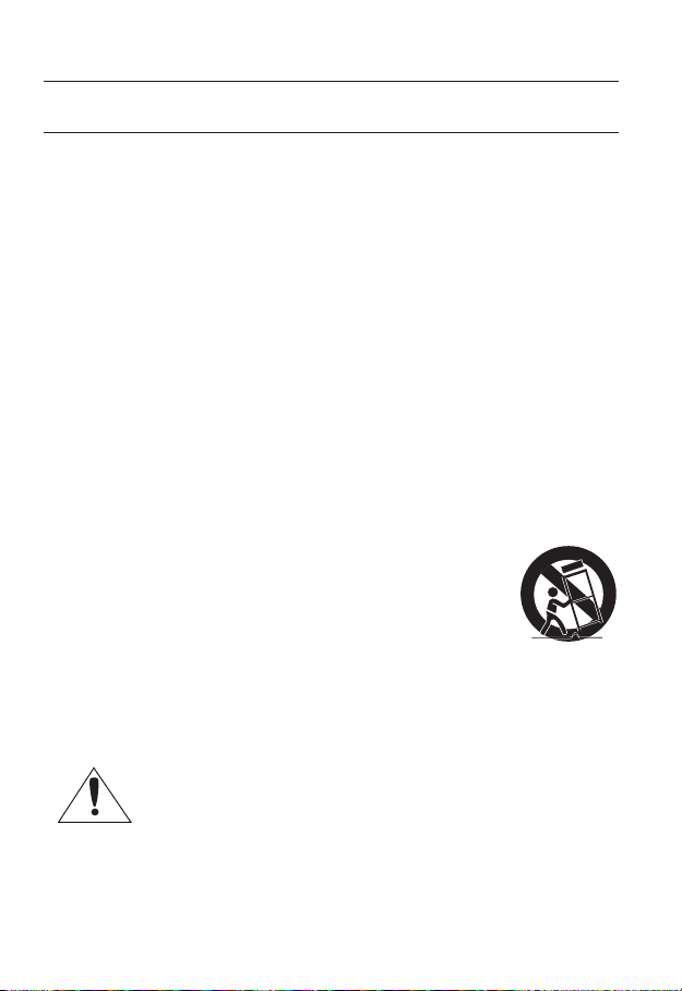
Use only with the cart, stand, tripod, bracket, or table specifi ed by
12.
the manufacturer, or sold with the apparatus. When a cart is used,
use caution when moving the cart/apparatus combination to avoid
injury from tip-over.
Unplug this apparatus during lightning storms or when unused for
13.
long periods of time.
Refer all servicing to qualifi ed service personnel. Servicing is required when the
14.
apparatus has been damaged in any way, such as powersupply cord or plug is
damaged, liquid has been spilled or objects have fallen into the apparatus, the apparatus
has been exposed to rain or moisture, does not operate normally, or has been dropped.
6_ overview
Apparatus shall not be exposed to dripping or splashing and no objects
filled with liquids, such as vases, shall be placed on the apparatus

CONTENTS
OVERVIEW
2
INSTALLATION &
CONNECTION
14
CAMERA SETUP
27
NETWORK CONNECTION
AND SETUP
36
6 Important Safety Instructions
9 Product Features
9 Recommended PC Specifi cations
10 What’s Included
11 At a Glance
14 Disassembling
15 Inserting/Removing an SD
Memory Card
16 Memory Card Information (not
included)
17 Connecting with other Device
21 Installation
21 Optional Accessories for
Installation
27 How to use the menu key
28 Main Menu
28 Profi le
29 Camera Setup
33 Privacy Zone
34 Others
35 System Info
35 Language
36 Connecting the Camera to an
IP Router with the xDSL/Cable
Modem
37 Connecting the Camera to
an IP Router with Local Area
Networking
38 Connecting the Camera Directly
to a DHCP-Based xDSL/Cable
Modem
39 Connecting the Camera Directly
to Local Area Networking
40 IP Address Setup
41 Static IP Setup
44 Dynamic IP Setup
45 Port Range Forward (Port
Mapping) Setup
46 Connecting to the camera from a
shared local PC
46 Connecting to the camera from a
remote PC via the Internet
● OVERVIEW
English _7

overview
WEB VIEWER
47
SETUP SCREEN
55
APPENDIX
73
47 Connecting to the camera
48 Login
49 Installing ActiveX
50 Using the Live Screen
51 Backup
54 Using the SD Search Viewer
Screen
55 Accessing the Setup screen
55 Default Setup
60 System Setup
64 Overlay Setup
65 Event Setup
72 Network Setup
73 Profi le
74 Terminology
76 Specifi cations
80 Frame Rate (NTSC)
86 Frame Rate (PAL)
92 Troubleshooting
8_ overview

PRODUCT FEATURES
y
Support various communication protocols
Supports TCP/IP, UDP, RTP/RTSP, SMTP for email, and FTP protocols as well as various
internet protocols such as ARP, HTTP, HTTPS and DHCP.
y
Web Browser-based Monitoring
Using the Internet web browser to display the image in a local network environment.
y
Automatic Local IP Setup
Even a network novice can install it with minimum operations.
y
Alarm
If an alarm sensor is connected and it detects a motion, a message is sent to the
registered address via FTP/email (SMTP) or stored in the SD memory card, or an alarm
will signal to the alarm out terminal.
y
Intelligent Video Analysis
If an event rule is defi ned for the video analysis and it detects a motion in the confi gured rule
area, a message is sent to the registered address via FTP/email (SMTP) or stored in the SD
memory card, or an alarm will signal to the alarm out terminal.
PRECAUTIONS – INSTALLATION AND USE
y
Do not bend or drop the SD memory card.
y
Do not store or use the SD memory card in a high temperature, high humidity or dusty place.
y
Be careful not to apply foreign substances on the terminals of SD memory card.
y
In case of cleaning terminals, wipe gently with a soft cloth.
y
Before ejecting the SD memory card, release the checkbox <SD Card Record> in
<Alarm image> and press [Apply] button. (page 67)
y
If SD memory card have reached its lifespan, no data will be saved.
In this case, purchase a new one and replace the SD memory card.
RECOMMENDED PC SPECIFICATIONS
y
CPU : Pentium4 / 2.4GHz or higher
y
Operating System : Windows XP(Service
Pack2, Service Pack3) / Windows Vista
y
Resolution : 1024X768 pixels or higher
y
RAM : 512MB or higher
y
Web Browser : Internet Explorer 6.0 or
higher
y
Video Card : Radeon, Nvidia
y
Video Memory: 128MB
y
DirectX 8.1 or higher
● OVERVIEW
Compatible IP Routers
y
Linksys / D-Link / Netgear
Compatible PoE Switches
y
Linksys SRW224G4P / D-Link DES-1316 / SMC SMCPWR-INJ3
English _9
overview
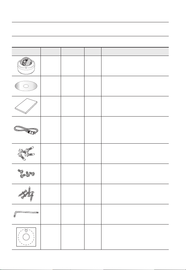
WHAT’S INCLUDED
Please check if your camera and accessories are all included in the product package.
Image Part name Standard Quantity Usage
Camera SNC-B5399 1
User Manual/
CD
IP INSTALLER
S/W
1
10_ overview
User
Manual
Cable for
test monitor
connection
Plastic
Anchor
Fixing
Screws
Tapping
Screws
L-wrench TORX T-20 1
Template ART PAPER 1 Guiding template for the installation
HUD 5 4
BH, M4 x L8,
SILVER
TH, M4xL30.
BLACK +O RING
1
Used to connect to a monitor for camera
operation test.
1
For connecting to a surveillance monitor, use
BNC cable.
Used to fix the screws, for installation Insert
the anchor into a drilled hole (to reinforce the
strength).
Used when installing the case on the ceiling,
4
with pipe or wall mount. Used to stop up a hole.
4 Used for ceiling and wall installations
Used for assembling / disassembling the dome
cover.
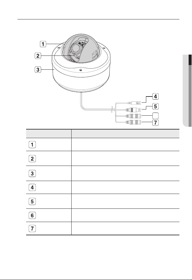
AT A GLANCE
Appearance
Item Description
Dome Cover Dome cover for the lens and unit protection.
● OVERVIEW
6
Heater
Main unit Main unit includes the lens, switch board, PCB boards and screws.
Power Port Used to plug the power cable.
Video Out Jack
Audio In Jack Used to connect to a microphone.
Audio Out Jack Used to connect to speakers.
Wipe out a dirty surface of the lens softly with a lens tissue or cloth to which you have applied
M
ethanol.
Do not touch the unit since it is hot when the heater is operating.
Operates if ambient temperature drops below 5°C, for defrosting the dome
cover.
Connects to the video input terminal of a monitor, which outputs the video
signal from the camera.
English _11
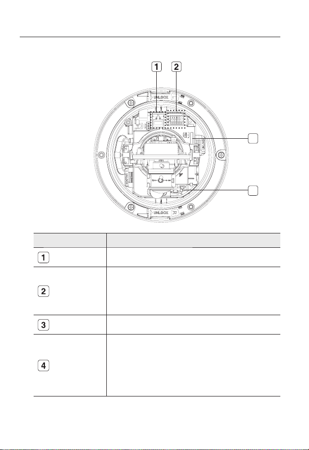
overview
Inside
Item Description
Network Port Used to connect a PoE or LAN cable.
Alarm In / Out
terminals
SD Memory Card
Compartment
Reset Button
3
4
Alarm in/out terminals can be configured as follows:
- ALARM IN : Terminal for Alarm Input.
- ALARM OUT : Terminal for Alarm Output.
- GND : Grounding terminal.
Compartment for the SD memory card.
Resets the camera settings.
Press the button for about 3 seconds, and the system indicator turns off and
will restart.
Resetting the camera requires reconfiguration of network settings (IP
J
address, subnet mask, gateway address etc.) using the IP Installer
software application.
12_ overview
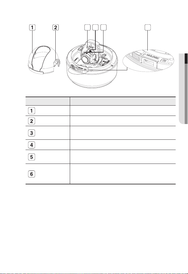
Components
Item Description
Inner Cover
3 4 5 6
● OVERVIEW
Cover for the main unit’s protection.
Side wing hooks
Monitor Out
ZOOM lever
Focus lever
Lock Release
By lifting it while gently pressing the both ends, you can separate the inner cover.
Using the test monitor cable, you can connect to a mobile display for camera
test.
You can adjust or fix the zoom ratio
Turn the barrel left or right to adjust the focus, and turn the knob clockwise to
lock the focus.
To separate the bracket from the main unit for the installation or to separate the
camera from an installed camera, push this release and turn the main unit in the
marked direction of <UNLOCK>.
English _13
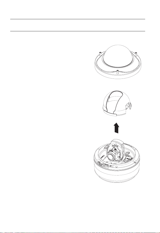
installation & connection
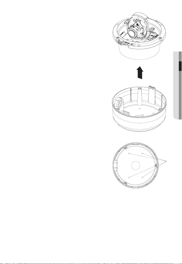
DISASSEMBLING
To connect the alarm in/out, the dome cover and lens cover are to be separated.
1.
Using the L-wrench provided, loosen 3
screws by turning them counterclockwise
and separate the dome cover.
2.
Lift up the inner cover while gently pressing
its both ends to separate it from the unit.
14_ installation & connection
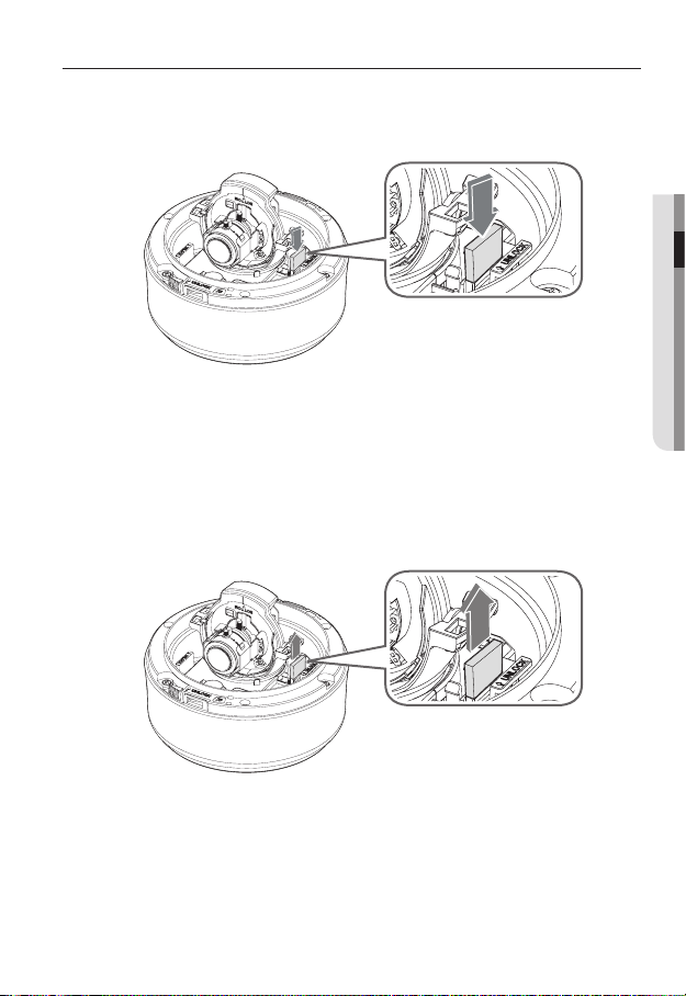
INSERTING/REMOVING AN SD MEMORY CARD
Inserting an SD Memory Card
Push the SD memory card in the direction of the arrow shown in the diagram.
Do not insert the SD memory card while it’s upside down by force. Otherwise, it may damage the
J
SD memory card.
Removing an SD Memory Card
Gently press down on the exposed end of the memory card as shown in the diagram to
eject the memory card from the slot.
● INSTALLATION & CONNECTION
Pressing too hard on the SD memory card can cause the card to shoot out uncontrollably from the
J
slot when released.
Before ejecting the SD memory card, release the checkbox <SD Card Record> in <Alarm
image> and press [Apply] button. (page 67)
English _15
installation & connection
MEMORY CARD INFORMATION (NOT INCLUDED)
What is a memory card?
The memory card is an external data storage device that has been developed to offer an
entirely new way to record and share video, audio, and text data using digital devices.
Selecting a memory card that’s suitable for you
Your camera supports SDHC memory cards.
You may, however, experience compatibility issues depending on the model and make of
the memory card.
Your camera supports SD memory cards.
Note that supported memory card capacity is up to 2GB.
For your camera, we recommend you use a memory card from the following manufacturers:
SDHC/SD Memory Card: Panasonic, Sandisk, Toshiba
Your camera supports 128MB to 16GB (SD Card : 2GB) of memory card capacity.
Playback performance can be affected depending on the speed of memory card, so use
the high-speed memory card.
To ensure proper recording of video data, we recommend you use a memory card that
supports at least read/write speed 10Mbps and Class 6.
Memory Card Use
SD and SDHC memory cards feature a switch that disables writing data on to the media.
Having this switch to the Lock position will prevent accidental deletion of data stored in the
memory card but at the same time will also prevent you from writing data on to the media.
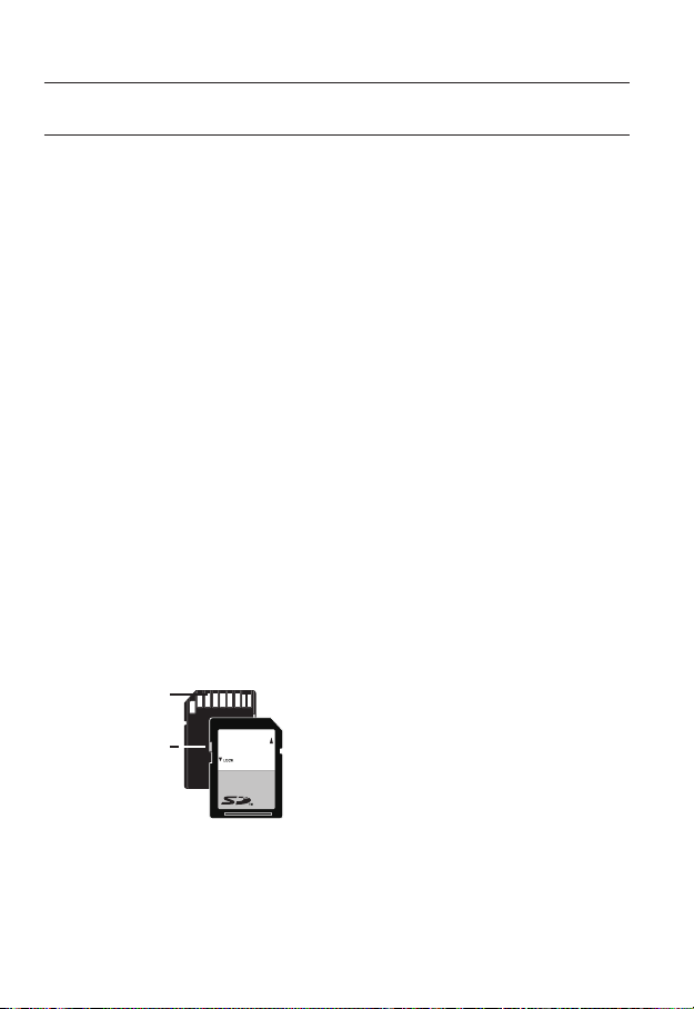
Memory Card Components
❖
Contacts
Lock Switch
SDHC
16_ installation & connection
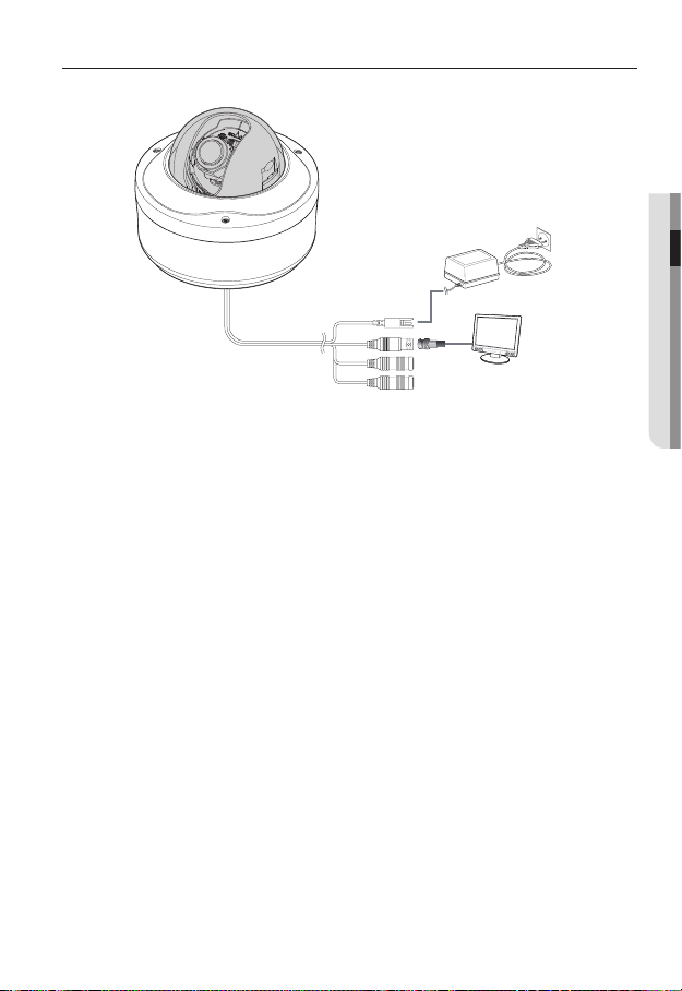
CONNECTING WITH OTHER DEVICE
Power Supply
Connect the power adaptor and camera’s power in jack.
Be careful not to reverse the polarity when you connect the power cable.
J
You can also use a router featuring PoE (Power over Ethernet) to supply power to the camera.
Connecting to the monitor
Connect the camera’s Video Out jack and the monitor’s video in jack.
● INSTALLATION & CONNECTION
Power
Monitor
English _17
installation & connection
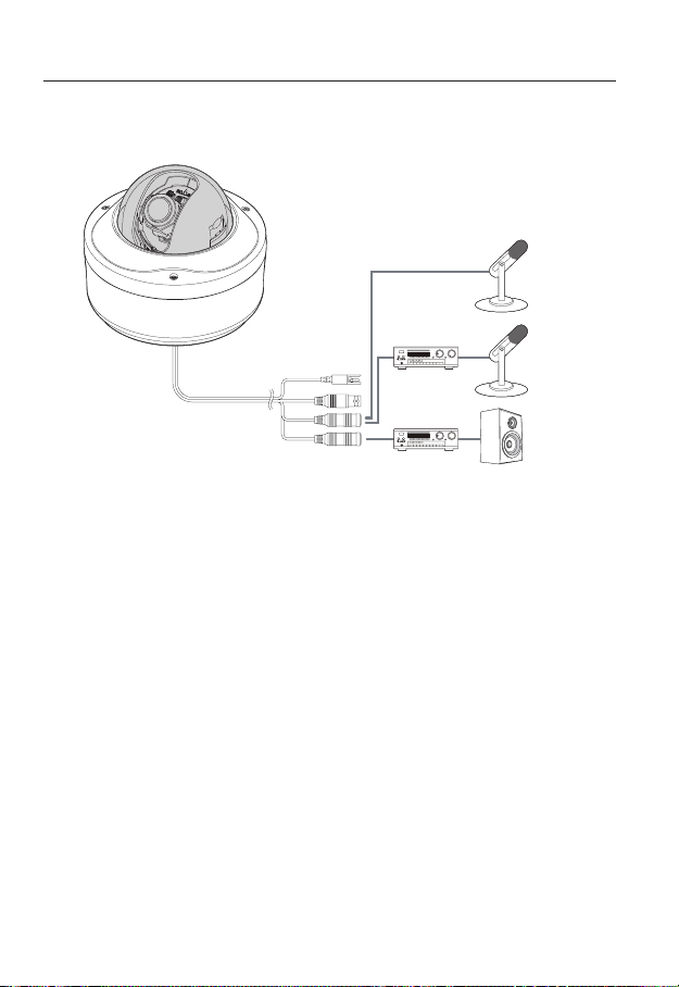
Connecting to Audio Input/Output
LINE-OUT
Microphone
Microphone
LINE-IN
Connect the AUDIO IN port of the camera with the microphone directly or LINE OUT
1.
port of the amplifi er that the microphone is connected to.
y
Direct Mic Connection : Set Audio Input Gain high (10). (Refer to page 56)
y
Line Out Connection : Set Audio Input Gain low (1). (Refer to page 56)
Connect the AUDIO OUT port of the camera with the LINE IN port of the speaker.
2.
18_ installation & connection
Speaker
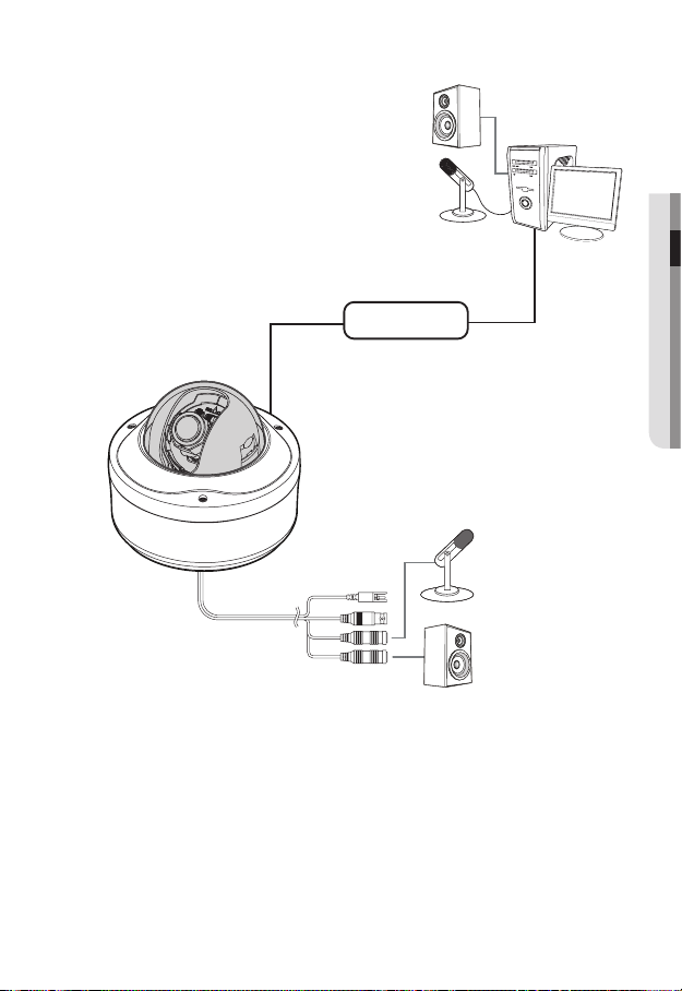
Audio I/O Block Diagram
● INSTALLATION & CONNECTION
PC
Network
Microphone
Speaker
y
Audio Codec
G.711 PCM. µ-law 64kbps 8kHz sampling
y
Full duplex Audio
y
Audio in
Used for mono signal line input (Max.2.4 Vpp)
y
Audio out
Used for mono signal line output (Max.2.4 Vpp)
y
Line out impedance
600
English _19
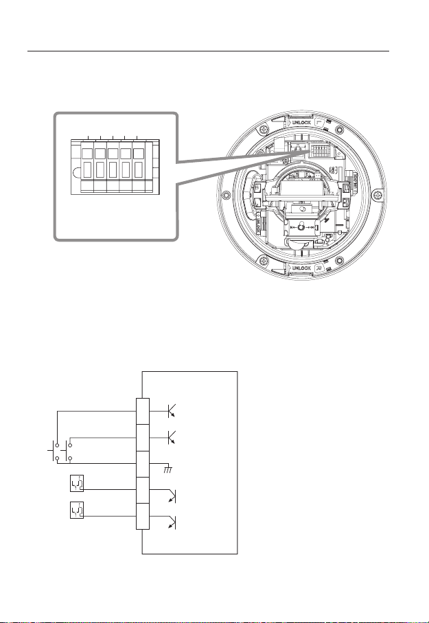
installation & connection
Connecting to the I/O port box
Connect the Alarm I/O cable to the corresponding port of the inner port box.
5 4 3 2 1
1,2 : ALARM IN 1,2
3 : GND
4,5 : ALARM OUT 1,2
y
ALARM IN 1, 2 : Used to connect the alarm input signal.
y
GND : Used for earth-grounding.
y
ALARM OUT 1, 2 : Used to connect the alarm output signal.
Alarm I/O Wiring Diagram
External Relay
External Relay
ALARM IN 1
ALARM IN 2
ALARM OUT 1
ALARM OUT 2
GND
1
2
3
4
5
20_ installation & connection
INSTALLATION
Precautions before installation
Ensure you read out the following instructions before installing the camera:
y
Select an installation site (ceiling or wall) that can endure at least 5 times of the
camera weight.
y
Stuck-in or peeled-off cables can cause damage to the product or a fi re.
y
For safety purposes, keep anyone else away from the installation site.
And put aside personal belongings from the site, just in case.
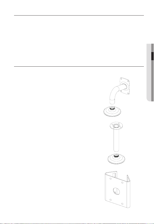
OPTIONAL ACCESSORIES FOR INSTALLATION
For your easier installation, you can purchase appropriate optional accessories available.
1.
WALL MOUNT ADAPTOR(SCX-300WM)/HANGING
MOUNT(SCX-300HM)
This adaptor is used when installing the dome camera
onto a wall.
2.
CEILING MOUNT ADAPTOR(SCX-300CM)/
ING MOUNT(SCX-300HM)
This adaptor is used when installing the dome
camera on a concrete ceiling.
HANG-
● INSTALLATION & CONNECTION
3.
POLE MOUNT ADAPTOR(SCX-300PM)
This is an adaptor for WALL MOUNT ADAPTOR
(SCX-300WM) installation on a pole whose diameter is bigger than 80mm.
English _21
installation & connection
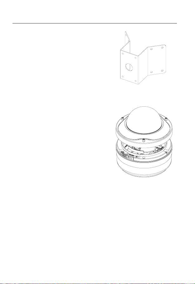
CORNER MOUNT ADAPTOR (SCX-300KM)
4.
This is an adaptor for WALL MOUNT ADAPTOR
(SCX-300WM) installation on the corner of wall joint.
Installing on the ceiling directly
1.
Using the L-wrench provided, loosen 3
screws by turning them counterclockwise
and separate the dome cover.
22_ installation & connection
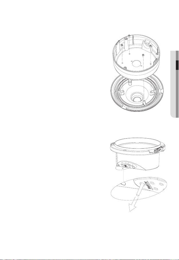
Loosen 3 screws by turning them
2.
counterclockwise, press both left and right
lock releases inwards (in arrow direction) to
unlock the stopper, and then separate the
camera from the case.
Drill holes (diameter 5mm, more than 35mm
3.
deep) on the ceiling by matching to the holes
on the case bed, and insert plastic anchors
(HUD 5) fully into the holes. Fix the case bed
on the ceiling by using Tapping Screws (TH
M4xL30). (4 places)
● INSTALLATION & CONNECTION
Connect power and video cables and arrange cable running not to damage or
4.
squeeze them, and assemble the camera unit in the reverse way.
Adjust the lens aiming to your desired direction.
5.
Assemble the Dome Cover.
6.
For waterproof purpose, fix and secure the bolt using L-wrench provided.
English _23
installation & connection
Flushed installation on the ceiling
Using the provided template, drill a hole for the camera unit and fi xing holes (diameter
1.
5mm, more than 35mm deep) on the ceiling. Insert the plastic anchors (HUR-5) fully
into the fi xing holes.
Separate the dome cover and case.
2.
For separating dome cover and case, refer to the steps 1 and 2 of “Installing on
the ceiling directly”.
Connect power and video cables and arrange cable running not to damage or
3.
squeeze them.
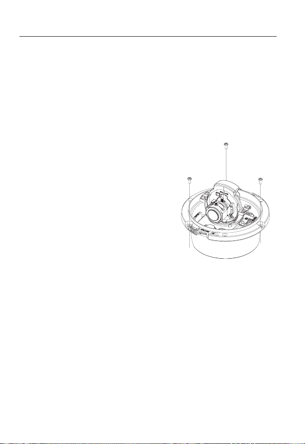
Remove the case assembly screws from the
4.
camera module.
Insert the camera module into the camera
5.
hole, and install it by fastening the Tapping
Screws (TH, M4xL30) by matching the fi xing
holes (3 places).
Assemble the Dome Cover.
6.
Refer tot the step 6 of “Installing on the
ceiling directly".
24_ installation & connection
Installing on adaptors (sold separately, SCX-300WM, 300CM,
300KM, 300PM)
Separate the dome cover and case.
1.
For separating dome cover and case, refer
to the steps 1 and 2 of “Installing on the
ceiling directly”.
Assemble and secure the case and adaptor
2.
(sold separately) using 4 fi xing screws (BH,
M4xL8, provided).
Connect power and video cables and
3.
arrange cable running not to damage or
squeeze them, and assemble the camera
unit in the reverse way.
Assemble the Dome Cover.
4.
Refer tot the step 6 of “Installing on the
ceiling directly".
Connecting additional alarm cables
Separate the dome cover and case to
1.
connect alarm cable.
For separating dome cover and case, refer
to the steps 1 and 2 of “Installing on the
ceiling directly”.
Tear off the long rubber plug as illustrated in
2.
the fi gure.
Through the hole opened in step 2 by tearing
3.
the plug off, insert the alarm cable and
connect it to the alarm terminal of the PCB.
Assemble the camera module and the case.
4.
Refer tot the step 4 of “Installing on the ceiling
directly".
Adjust the lens aiming to your desired
5.
direction and assemble the dome cover.
● INSTALLATION & CONNECTION
English _25
installation & connection
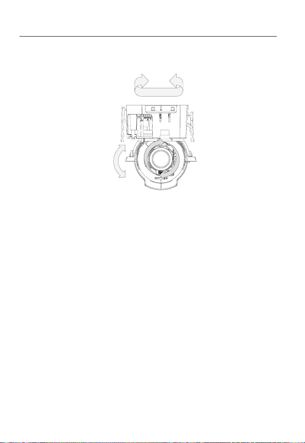
Adjusting the monitoring direction for the camera
Panning
Tilting
Lens rotation
You can adjust the camera direction only when the camera is fixed on the ceiling.
Then, turning the camera to the left or right is referred to as "Panning", while tilting the
angle is "Tilting". For panning, the panning limit is 220° for the clockwise, and 120° for the
counterclockwise, a total of 340° enabled; further rotation is stopped by the stopper.
26_ installation & connection
camera setup
You can configure the camera settings using the Web Viewer.
For accessing the Web Viewer, refer to "Network Connection and Setup". (page 36)
M
HOW TO USE THE MENU KEY
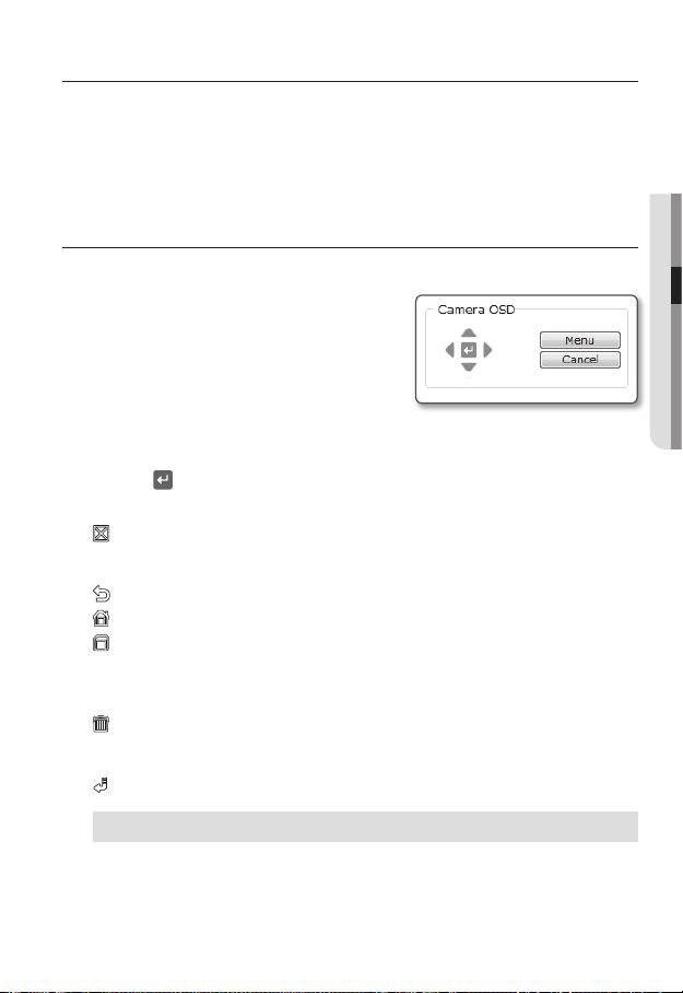
Follow the steps below if you run the Web Viewer for setting the menus.
1.
Launch the Web Viewer.
2.
From the [Camera OSD] menu in the left
pane, click [Menu].
The <MAIN MENU> screen appears.
3.
Click the Up/Down (
desired item.
Click
the four direction (
4.
To change the value of a selected item, click the Left/Right (
5.
Click [
6.
].
Your changes will be applied.
: Exits the menu setup screen.
Before exiting the setup screen, select [SAVE] to save your settings, or [QUIT] to
cancel them.
: Saves your settings and returns to the previous screen.
: Returns to the main menu.
: Use this icon if you want to save your settings after you specified the mask area and
privacy area, etc.
Once you saved your settings, the changes remain intact even if you select [QUIT] on
exit.
: Use this icon if you want to delete a mask, or privacy area, etc.
Once you deleted your settings, the deletions remain valid even if you select [QUIT] on
exit.
: This arrow appears next to a menu that contains sub items.
) buttons to move to a
▲▼
) buttons to navigate through the menu items.
▲▼◄ ►
◄ ►
) buttons.
● CAMERA SETUP
For the items with the "*" mark on the right, You can get help from "Terminology". (page 74)
If intelligent video analysis is enabled, camera’s OSD menu operation can be set as an event.
J
English _27
camera setup
**
MAIN M ENU
**
CAMERA SET
PRIVACY ZONE
OTHER S ET
SYSTEM INFO
LANGUAG E
*
STANDARD
ITS
BACKLIG HT
DAY/NIGHT
GAMING
CUSTOM
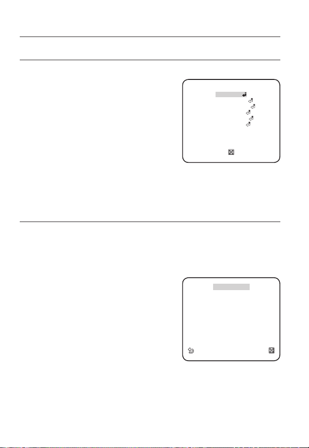
MAIN MENU
You can configure the camera settings to your preference.
y
PROFILE
You can select a mode that is appropriate to the
camera installation environment.
y
CAMERA SET
Confi gure the camera functions and settings.
y
PRIVACY ZONE
You can confi gure the privacy settings.
y
OTHER SET
You can confi gure more settings including
FACTORY DEFAULTS.
y
SYSTEM INFO
Shows the camera version and type.
y
LANGUAGE
Select a preferred one from the supported languages.
PROFILE
You can select one from the pre-determined modes as appropriate to your specific camera installation
environment.
Your selection on each item in PROFILE will affect all other settings of the camera. For the
setting, refer to "PROFILE". (page 73)
For selecting and saving each menu item, refer to "How to use the menu key". (page 27)
y
STANDARD
Automatically optimizes the camera settings to
the normal environment.
y
ITS
This setting enables you to analyze the traffi c
situation and take the traffi c information at a glance.
y
BACKLIGHT
This setting enables you to view a sharp background
and object even in a severe backlight scene.
y
DAY/NIGHT
Automatically optimizes the camera settings to the day and night scene.
y
GAMING
This automatically confi gures the settings so that you can work in a stable illumination
condition as indoors.
y
CUSTOM
Your change to any of the PROFILE settings will switch the display to CUSTOM.
28_ camera setup
**
MAIN MENU
PROFILE
CAMERA SET
PRIVACY ZONE
OTHER SET
SYSTEM INFO
LANGUAGE
◄
PROFILE
*
STANDARD
ITS
BACKLIGHT
DAY/NIGHT
GAMING
CUSTOM
**
►
CAMERA SETUP
CAMERA ID
BCD EFG HIJKLMNO PQR STU VWXYZO
123 456 789
: ?
_
+
*() /
SP►► ◄◄ SP LOCATION
- - - - - - - - - - - - - - - - - - - - - - - -
- - - - - - - - - - - - - - - - - - - - - - - - -
ALC
BACKLIG HT OFF
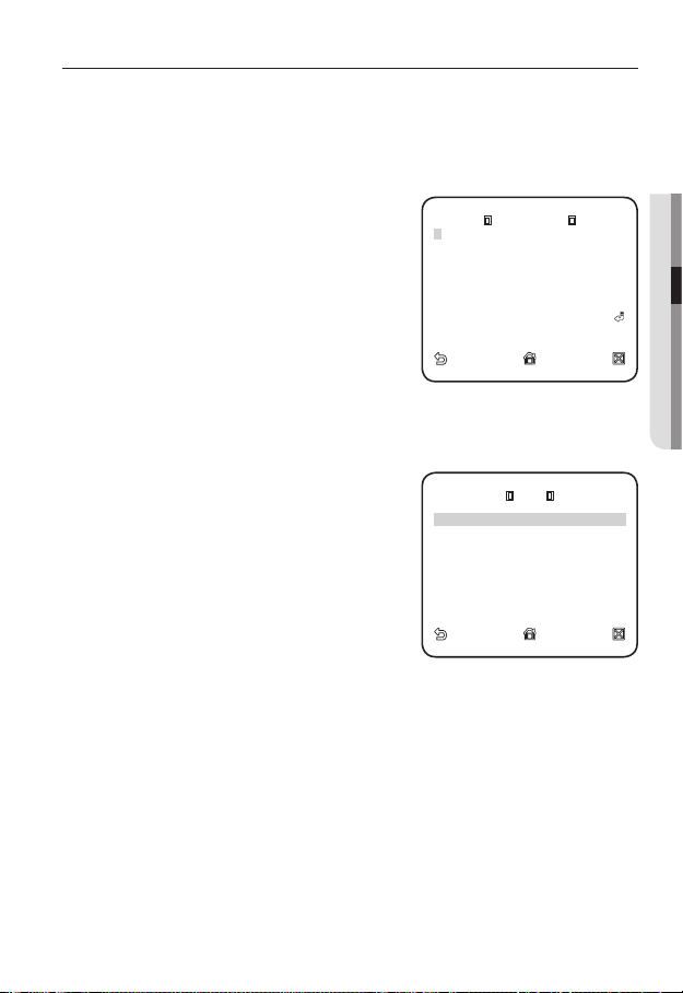
You can configure the general settings of the camera module.
For selecting and saving each menu item, refer to "How to use the menu key". (page 27)
CAMERA ID
Provide the ID and position for a camera that displays on the screen.
1.
Select <CAMERA SET> - <CAMERA ID>.
Use the four direction (
2.
▲▼◄ ►
) buttons to
select a desired character.
In the lower input box of the screen, the
selected character will be entered.
You can enter up to 54 characters including alphabets,
numbers and special characters.
When done, continue to select <LOCATION>
3.
to specify the display position of the camera ID.
IRIS
You can set the iris to control the intensity of radiation incoming to the camera.
Select <CAMERA SET> - <IRIS>.
1.
Use the left/right (
2.
<ALC>.
y
ALC : Controls the luminance automatically.
LEVEL : Select the global brightness level.
BACKLIGHT : Select WDR or BLC.
WDR : Defi ne the composition for weight
factor, the shutter speed in WDR level, and
select outdoor or indoor for white balance
setup.
-
BLC (Backlight compensation) : Confi gure the backlight compensation area by
defi ning the area size and location.
) buttons to select
◄ ►
CAMERA ID
A
BCDEFGHIJKLMNOPQRSTUVWXYZO
123456789
: ?
SP►► ◄◄ SP LOCATION
-
- - - - - - - - - - - - - - - - - - - - - - - -
- - - - - - - - - - - - - - - - - - - - - - - - -
LEVEL
BACKLIGHT OFF
_
+
ALC
*()/
[ 00]
● CAMERA SETUP
----
----
I
If the iris is set to <ALC>, fi xing the iris is your priority when you adjust AE and the shutter speed.
M
English _29
camera setup
CAMERA ID ON
IRIS ALC
MOTION (F.FAST)
--DNR MID
SHUTTER OFF
SENS-UP AUTO X4
FLICKER LESS OFF
XDR MID
DIS OFF
WHITE B AL
DIGITAL ZOOM OFF
DETAIL
[
2
]
AGC COL OR SUP MID
REVERSE OFF
POSI/NE GA +
PIP OFF
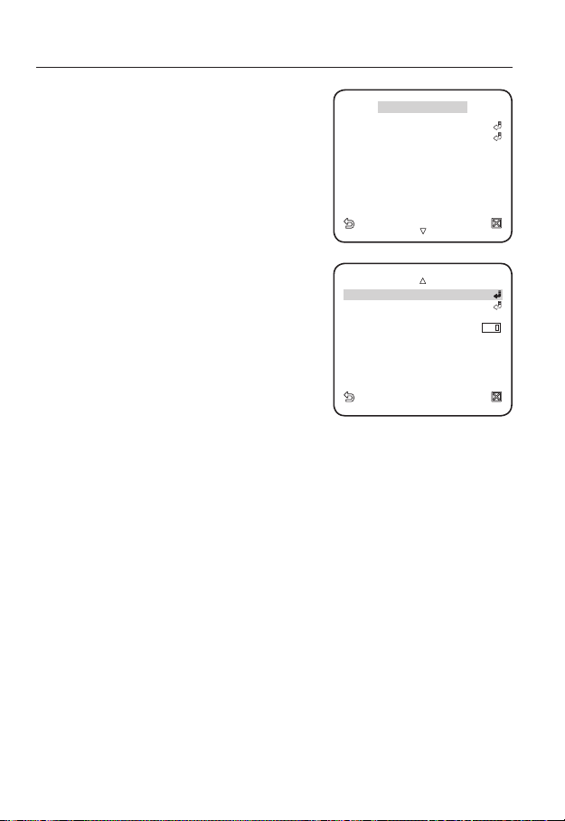
MOTION
You can specify a level of AGC for controlling the
camera motion.
Select F.FAST if you want to monitor a very fast
moving object in a low contrast scene, and S.SLOW
if monitoring a very slow moving, inanimate object in
the same condition.
As long as DAY/NIGHT is set to AUTO, the
◄
CAMERA SET
CAMERA ID ON
IRIS ALC
MOTION (F.FAST)
DNR MID
SHUTTER OFF
SENS-UP AUTO X4
FLICKERLESS OFF
XDR MID
DIS OFF
►
---
<MOTION> menu is not available.
DNR
Reduces the noise on the screen.
This is useful, especially for a noisy screen.
Set it to <USER>, you can specify the level.
SHUTTER
The SHUTTER menu is used to set the fixed fast
electronic shutter or auto fast electronic shutter.
DAY/NIGHT AUTO
WHITE BAL
DIGITAL ZOOM OFF
DETAIL
AGC COLOR SUP MID
REVERSE OFF
POSI/NEGA +
PIP OFF
[
]
2
SENS-UP
If the brightness of the video signal is too low, the Slow Shutter function will be activated.
Slow Shutter can collect the individual max frame rate to adjust the setting.
FLICKERLESS
If set to <ON>, the shutter speed will be fixed to 1/100 second. This will prevent possible
screen distortion due to a mismatch between the vertical sync frequency and the blinking
frequency of the lighting.
If SHUTTER is set to AUTO, FIX, EXT mode / SENSE UP to FIX / AGC to FIX, the <DIS> menu will be
disabled.
XDR
This will correct a brightness difference between different scenes for the optimal visibility.
The higher the value is, the higher the correction level is.
DIS
Automatically compensates for the flicker on the screen.
If set to <ON>, the image will be enlarged with digital zoom as much area as
compensated.
30_ camera setup
 Loading...