

Page 1
Summary of Product
Service Manual
4-1
Samsung Electronics
4
4
4. Summary of Product
This chapter describes the functions and operating principal of the main components.
4.1 Printer Components
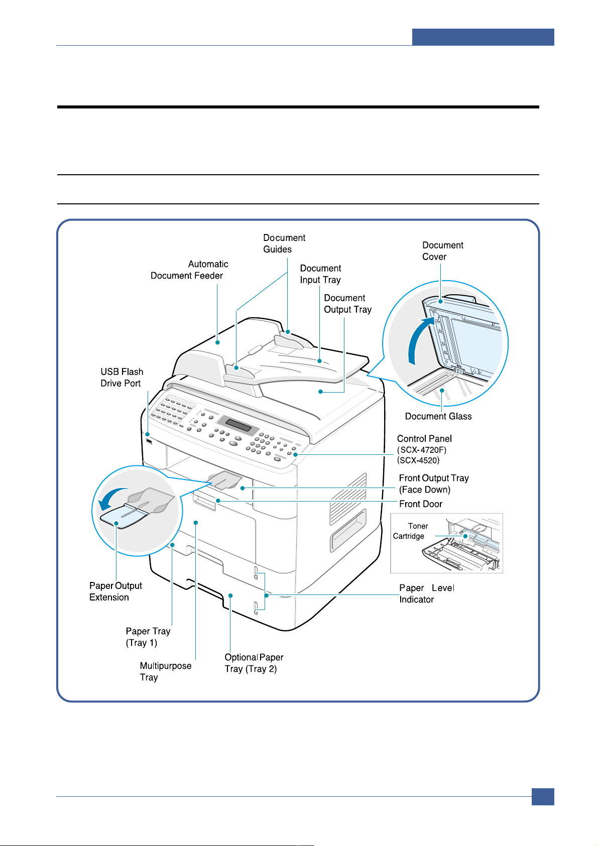
4.1.1 Front View
Page 2
Service Manual
Summary of Product
4-2
Samsung Electronics
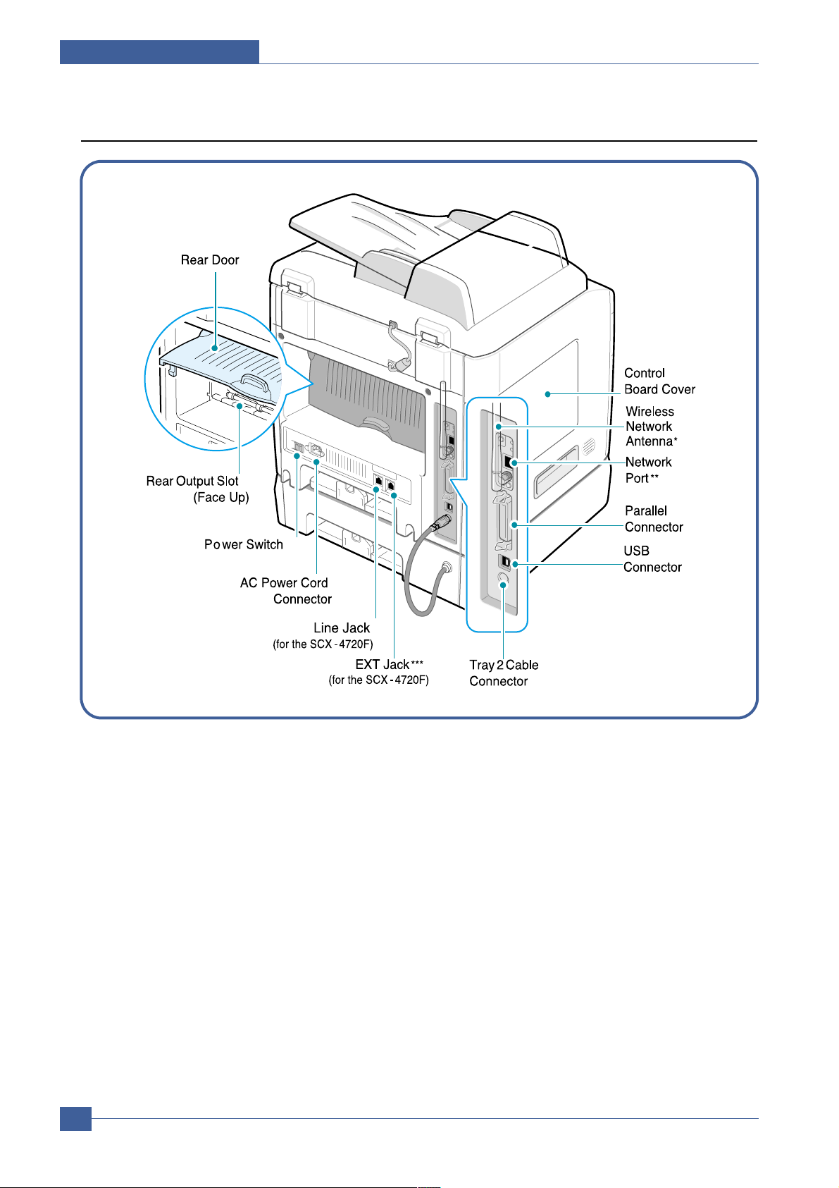
4.1.2 Rear View
* This wireless network antenna is not supplied with the machine. It is an option that must be purchased and
installed separately. (Option Function)
** The network port is not fitted as standard on the machine. You can purchase an optional Network Card and
install it separately.
*** If your country has a different telephone connection system, this socket may be blocked.
Page 3
Summary of Product
Service Manual
4-3
Samsung Electronics
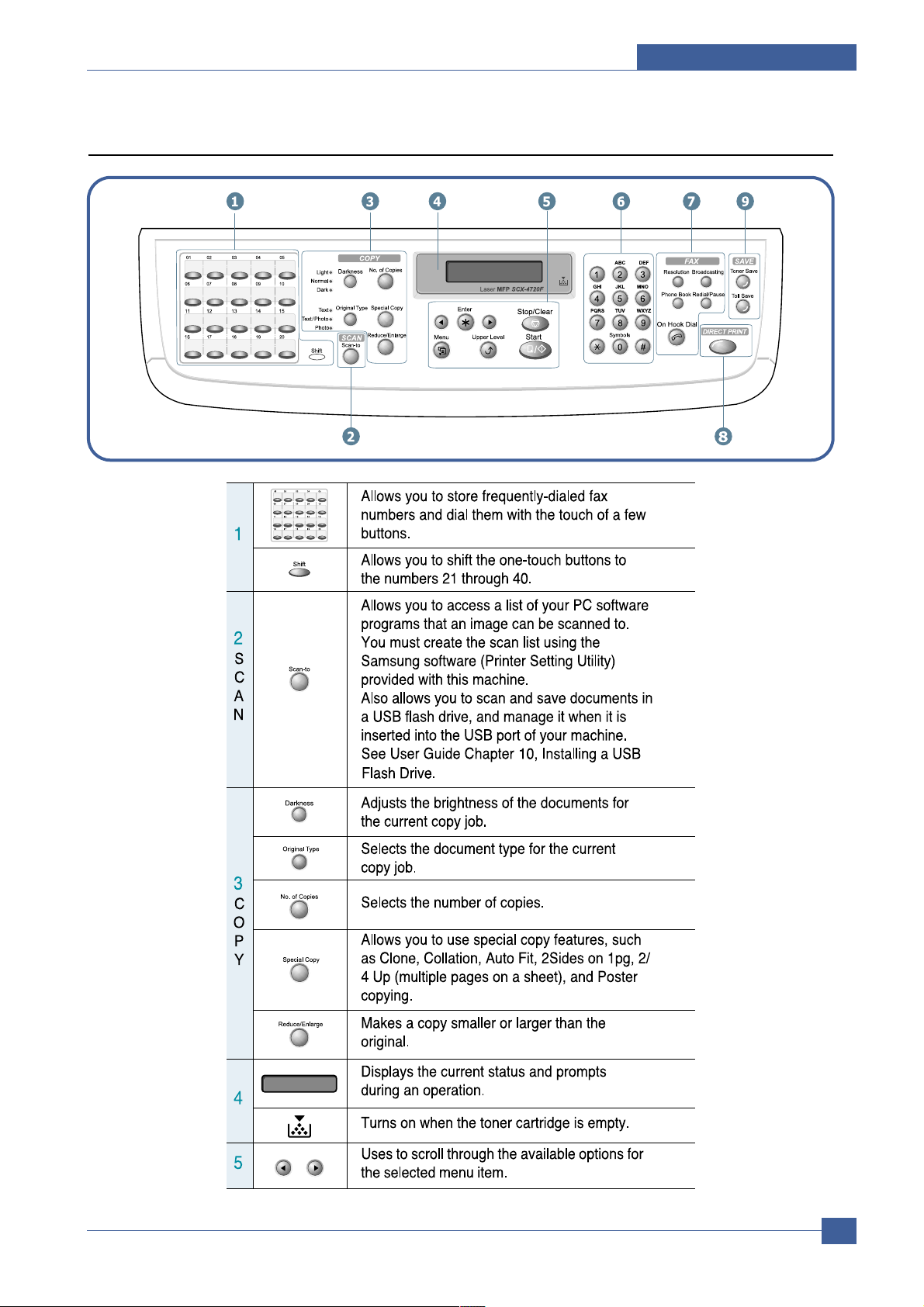
4.1.3 Control Panel (SCX-4720F)
Page 4
Service Manual
Summary of Product
4-4
Samsung Electronics
Page 5
Summary of Product
Service Manual
4-5
Samsung Electronics
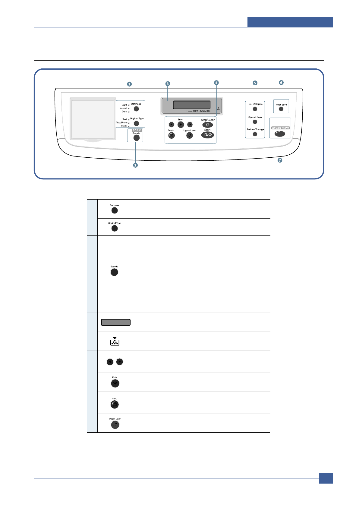
Control Panel (SCX-4520)
1
Adjusts the brightness of the documents for
the current copy job.
Selects the document type for the current
copy job.
Allows you to access a list of your PC software
programs that an image can be scanned to.
2
S
C
A
N
You must create the scan list using the
Samsung software (Printer Setting Utility)
provided with this machine.
Also allows you to scan and save documents in
a USB flash drive, and manage it when it is
inserted into the USB port of your machine.
See User Guide Chapter 10, Installing a USB
Flash Drive.
Displays the current status and prompts
during an operation.
3
Turns on when the toner cartridge is empty.
Uses to scroll through the available options for
the selected menu item.
Confirms the selection on the display.
4
Enters Menu mode and scrolls through the
menus available.
Sends you back to the upper menu level.
Page 6
Service Manual
Summary of Product
4-6
Samsung Electronics
4
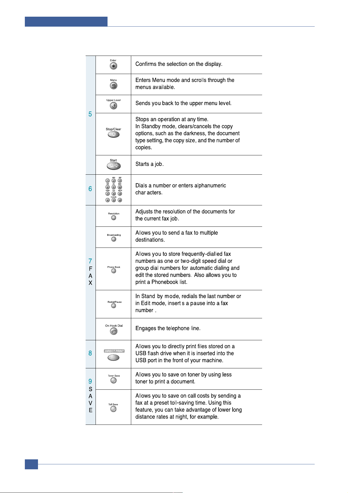
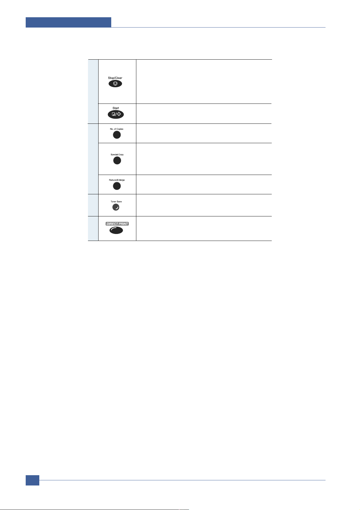
Stops an operation at any time.
In Standby mode, clears/cancels the copy
options, such as the darkness, the document
type setting, the copy size, and the number of
copies.
Starts a job.
5
Selects the number of copies.
Allows you to use special copy features, such
as Clone, Collation, Auto Fit, 2Sides on 1pg, 2/
4 Up (multiple pages on a sheet), and Poster
copying.
Makes a copy smaller or larger than the original.
Allows you to save on toner by using less
toner to print a document.
Allows you to directly print files stored on a USB
flash drive when it is inserted into the USB port
in front of your machine.
6
7
Page 7

Summary of Product
Service Manual
4-7
Samsung Electronics
4.2 System Layout
The SCX-4720F/4520 is roughly made up Main Control part, Operation Panel part, Scanner part, Line Interface
part and Power part. Each Part is separated Module which focus on common and standard design of different
kind products. main control part adopting Fax & LBP Printer exclusive Controller is composed of 2 CPU and
1 Board. Scanner part is composed of ADF and Platen and is connected with Main by Harness.
4.2.1 Feeding section
There is a universal cassette which automatically loads paper and the manual feed which supplies paper single
sheet at a time. The cassette has a friction pad which separates paper to ensure single sheet
feeding, and it has a sensor, which checks when the paper tray is empty.
- Feeding Method: Universal Cassette Type
- Feeding Standard: Center Loading
- Feeding Capacity: Cassette-250 sheets (75g/m2, 20lb paper standard)
Manual 1 sheet (Paper, OHP, Envelop, etc.)
- Paper detecting sensor: Photo sensor
- Paper size sensor: None
4.2.2 Transfer Ass’y
This consists of the PTL (pre-transfer lamp) and the Transfer Roller. The PTL shines a light onto the OPC drum.
This lowers the charge on the drum’s surface and improves transfer efficiency.
The transfer roller transfers toner from the OPC drum surface to the paper.
- Life expectancy: Over 60,000 sheets (at 15~30°C)
4.2.3 Driver Ass’y
- Gear driven power unit. The motor supplies power to the paper feed unit, the fuser unit, and the toner
cartridge.
4.2.4 Fixing Part(Fuser)
- The fuser consists of the Heat Lamp, Heat Roller, Pressure Roller, Thermistor, and Thermostat. It fixes toner to
the paper using pressure and heat to complete the printing job.
4.2.4.1 Temperature-Intercepting Device (Thermostat)
The thermostat is a temperature sensing device, which cuts off the power to the heat lamp to prevent
overheating fire when the heat lamp or heat roller overheats.
4.2.4.2 Temperature Detecting Sensor (Thermistor)
The Thermistor detects the surface temperature of the heat roller, this information is sent to the main processor
which uses this information to regulate the temperature of the heat roller.
4.2.4.3 Heat Roller
The surface of the Heat Roller is heated by the Heat Lamp. As the paper passes between the Heat and Pressure
rollers the toner is melted and fixed permanently to the paper. The surface of the roller is coated with Teflon. This
ensures that toner does not adhere to the roller surface.
Page 8

Service Manual
Summary of Product
4-8
Samsung Electronics
4.2.4.4 Pressure roller
The Pressure Roller mounted under the heat roller, it is made of a silicon resin, and the surface of the roller is
coated with Teflon. This ensures that toner does not adhere to the roller surface.
4.2.4.5 Safety Features
• To prevent overheating
- 1st protection device: Hardware cuts off when overheated
- 2nd protection device: Software cuts off when overheated
- 3rd protection device: Thermostat cuts off mains power to the lamp.
• Safety device
- Fuser power is cut off when the front cover is opened
- LSU power is cut off when the front cover is opened
- The temperature of the fuser cover's surface is maintained at less than 80ºC to protect the user and a caution
label is attached where the customer can see it easily when the rear cover is opened.
4.2.5 Scanner
This image is read using a photosensitive sensor. It consists of a CCD module, Connection board, ADF board,
AFE (Analog Front End), Image Processor (Located in CPU), platen glass and ADF mechanism.
• CCD Module Specification
1.Resolution: 600dpi/A4
2.Maximum scan wide: 8.5”
3.Color filter: Red, Green, Blue
4.Output channel: 3 channels (R, G, B)
5.Effective pixel: 5,400 pixel *3
6.Voltage: 24V & 5V
7.Pre-heating time: Maximum 30 seconds (70% of light output reached)
8.The life span of a lamp: 30,000 hours (25oC)
• Image Processor Specification
1.Operating frequency: 66MHz
2.Image sensor interface: 200/300/600 dpi CIS or CCD
3.Line time: Copy, FAX, Binary (Lineart, Halftone) PC Scan: 1.5ms/Line Color PC Scan (Grey, 256 Color,
True Color): 4.5ms/Line
4.A/D conversion: 10bit conversion
Page 9

Summary of Product
Service Manual
4-9
Samsung Electronics
4.2.6 LSU (Laser Scanner Unit)
This is the core of the laser printer. It converts the video data received from the computer into an electrostatic
latent image on the surface of the OPC drum. This is achieved by controlling the laser beam and exposing the
surface of the OPC drum to the laser light. Arotating polygon mirror reflects the laser light onto the OPC and each
side of the mirror is one scan line. The OPC drum turns as the paper feeds to scan the image down the page.
The /HSYNC signal is created when the laser beam from LSU reaches the end of the polygon mirror and this
signal is sent to the controller. The controller detects the /HSYNC signal to adjust the vertical line of the image on
paper. In other words after the /HSYNC signal is detected the image data is sent to the LSU to adjust the left margin
on the paper.
Page 10

Service Manual
Summary of Product
4-10
Samsung Electronics
4.2.7 Toner Cartridge
The toner cartridge is an integral unit containing the OPC unit and toner unit. The OPC unit consists of the
OPC drum and charging roller, and the toner cartridge unit consists of the toner, supply roller, developing
roller, and blade (Doctor blade)
- Developing Method: Non magnetic 1 element contacting method
- Toner: Non magnetic 1 element shatter type toner
- The life span of toner: 3,000 sheets (IDC Pattern/A4 standard)
- Toner remaining amount detecting sensor: Yes
- OPC Cleaning: Electrostatic process
- Management of waste toner: Collect the toner using a Cleaning Blade
- OPC Drum protecting Shutter: Yes
- Classifying device for toner cartridge: ID is classified by interruption of the frame channel
-950V
-430V
-580V
Page 11

Summary of Product
Service Manual
4-11
Samsung Electronics
4.3 Main PBA
The Engine Board and Controller Board have been integrated into a single PBA. This consists of the CPU,
printer scanner and line control functions. The CPU functions as the bus controller, I/O handler, motor driver
and PC inter-face. The main board sends the Current Image Video data to the LSU and manages the
Electrophotographic printing process. Circuits on the PBA drive include the main motor (paper feed,
cartridge, fuser), clutch driver, pre-transfer lamp driver, heat-lamp driver, CCD driver, scan motor driver,
modem and fan driver.
The signals from the paper feed jam sensor and paper empty sensor are inputted to the main board from
the power supply PBA..
1
2
15
11
12
21
22
13
28
29
9
24
23
18
7
8
27
26
25
20
16
19
10
3 5
4 6
14
15
17
1 IMAG E PRO CESS OR(CIP4E) U1 0 11 MOTOR DRIVER(TEA3718S) U5 21
LINE T RANSCEIVER
(74LVX161284) U36
2 PROCESSOR ASIC(S PGPm) U35 12 MOTOR DRIVER(TEA3718S) U9 22 VEDIC X- TAL(19.6MH z) OSC3
3
FLASH MEMORY
CODE - HIGH(29LV160DB) U23
13 USB 2.0(NET 2272) U50 23 CPU X- T AL(12MHz) OSC8
4
FLASH MEMORY
CODE - LOW( 29LV160DB) U30
14 CMOS- LOGIC(74HCT273) U58 24
MODEM X- T AL(28.2 24M Hz )
OSC6
5
FLASH MEMORY
PCL6- HIGH(29LV160DB) U24
15 CMOS- LOGIC(74HCT273) U59 25 USB HOS T X- T AL ( 6MHz) OSC9
6
FLASH MEMORY
PCL6- LOW(29LV160DB) U31
16 PANAS ONIC( 3V) BAT 2 26 PS3 DIMM CN10
7 SDRAM(K4S281632E) U45 17 VARTA(3.6V) BAT1 27 RAM DIMM CN 12
8 SDRAM(K4S281632E) U46 18 FPGA(EX64- FTQ64) U44 28 JACK USB J1
9 MODEM(FM336) U62 19
A/D CONVERTER(AFE- C IP4E)
U3
29 JACK DIN CN17
10 SRAM( K6R1 016VID) U2 20 USB HOST(TDOTG242) U148 30
1 IMAG E PROCESS OR(CIP 4E) U10 11 MOTOR DRIVER(TEA3718S) U5 21
LINE T RANSCEIVER
(74LVX161284) U36
2 PROCESSOR ASIC(S PGPm) U35 12 MOTOR DRIVER(TEA3718S) U9 22 VEDIC X- TAL(19.6MHz) OSC3
3
FLASH MEMORY
CODE - HIGH(29LV160DB) U23
13 USB 2.0(NET 2272) U50 23 CPU X- T AL(12MHz) OSC8
4
FLASH MEMORY
CODE - LOW( 29LV160DB) U30
14 CMOS- LOGIC(74HCT273) U58 24
MODEM X- T AL(28.2 24M Hz )
OSC6
5
FLASH MEMORY
PCL6- HIGH(29LV160DB) U24
15 CMOS- LOGIC(74HCT273) U59 25 USB HOS T X- T AL ( 6MHz) OSC9
6
FLASH MEMORY
PCL6- LOW(29LV160DB) U31
16 PANAS ONIC( 3V) BAT 2 26 PS3 DIMM CN10
7 SDRAM(K4S281632E) U45 17 VARTA(3.6V) BAT1 27 RAM DIMM CN 12
8 SDRAM(K4S281632E) U46 18 FPGA(EX64- FTQ64) U44 28 JACK USB J1
9 MODEM(FM336) U62 19
A/D CONVERTER(AFE- C IP4E)
U3
29 JACK DIN CN17
10 SRAM( K6R1 016VID) U2 20 USB HOST(TDOTG242) U148 30
Page 12

Service Manual
Summary of Product
4-12
Samsung Electronics
4.3.1 ASIC
Use 32Bit RISC Processor, ARM946ES,which is exclusive controller to execute Printer & FAX Function and to
execute operation block by flash memory within system program, and to control whole system.
• Main function block
• Completely Integrated System for Embedded Applications,
• 32 Bit Risc Architecture, Efficient and Powerful ARM9 Core.
• LSU Interface Module for Interfacing PVC or HPVC with LSU
• 2 Channel General Purpose DMAController for High Speed I/O
• Dual Memory Bus Architecture
• Operation Frequency : AHB Bus: 60MHz, Internal System Bus: 120MHz
• Operation Voltage : 3.3V
• POWER ON RESET TIME : Below 5.6ms
Page 13

Summary of Product
Service Manual
4-13
Samsung Electronics
4.3.2 Memory
The SCX-4720F/4520 has Flash ROM and DRAM memory units. There are 2 SODIMM sockets to enable extra DRAM
or FlashROM (Postscript Option) to be fitted.
On Domestic 9Korean) models additional Mask ROM is also fitted: to store domestic Fonts such as PCLFont and
KS5895, KSSM etc.
- Capacity : 32MByte
- Access Time : 100nsec
4.3.3 Flash Memory
Record System Program, and download System Program by PC INTERFACE.
FAX for Journal List, and Memory for One Touch Dial, Speed Dial List.
- size : 4M Byte
- Access Time : 70 nsec
4.3.4 SDRAM
SDRAM is used as Swath Buffer in Printing, Scan Buffer in Scanning, ECM Buffer in FAX receiving, and System
Working Memory Area
-
size 32MB : 32Mbyte(Basic).
-
Max Frequency : 133MHz
-
store Fax Receive Memory Data by using Battery
4.3.5 Battery Backup (SCX-4720F only)
Backup power is provided by a 3.6V rechargeable Lithium battery. It provides power to the SD-RAM to retain any
faxes in memory when main power is lost. Typically backup power will last up to 43 hours. The battery requires 48
hours to charge from empty.
Page 14

Service Manual
Summary of Product
4-14
Samsung Electronics
4.3.6 Sensor input circuit
1) Paper Empty Sensor
The Paper Empty sensor (Photo Interrupter) on the SMPS/HVPS PBA (CON2-2) is monitored by the
CPU on signal (nP_EMPTY). When the cassette is empty the printer displays a message on the LCD
panel.
2) MP Sensing
Presence of paper in the MP tray is detected by operation of the MP Sensor (Photo Interrupter) on the
SMPS/HVPS PBA (CON2-14). The CPU monitors signal(MP_EMPTY) to recognize paper in the MP, and
paper is fed from MP if there is paper present.
3) Paper Feed Sensor, (Toner Cartridge Sensor)
When paper passes the actuator on the feed sensor (CON2-1), it is detected by the Photo interrupter. signal(nP_FEED) monitored by the CPU and this signal starts the process of creating the image after certain
delay time If the feed sensor is not detected within 1 sec. after paper is fed, a paper Jam0 occurs.
(Displayed on the LCD panel).
When a toner cartridge is inserted it also operates the Paper Feed sensor. Amessage is displayed on the
LCD if no cartridge is detected.
4) Paper Exit Sensor
This detects that paper exits cleanly from the Machine using an exit sensor (CON2-24) on the engine
board and actuator on the frame. The monitors signal (P_EXIT) and detects the on/off time of the exit
sensor and if jam status is detected then JAM2 is displayed the on the LCD panel.
5) Cover Open Senser
The Cover open sensor actuator is located on the front cover and the senor is in the main frame. When the
front cover is opened the +24V supplies to the DC fan, solenoid, main motor, polygon motor part of LSU,
HVPS that are cut off. The CPU monitors
signal (COVER_OPEN)
to recognize when the cover is opened.
6) DC FAN / SOLENOID Driving
It is driven by a transistor and controlled by signal (FAN (SMPS, CON2-23)) bit of the CPU.
When it is high the fan is activated by turning on the TR, and it is off when the sleep mode is selected.
There are two solenoids and these are driven by the Paper Pick-up and MP signals. The drive time is
300ms. The diode protects the driving TR from the Back-EMF pulse which is generated when the solenoid is de-energized.
7) Motor Driving
The motor driving circuit is activated when the Driver IC is enabled. An A3977 (Motor driver IC) is used in
this case. The resistance Rs value of sensing and the voltage value of the V reference can be changed
by the motor driving voltage value.
Page 15

Summary of Product
Service Manual
4-15
Samsung Electronics
4.4 SMPS & HVPS
The SMPS and HVPS are on one integrated board.
The SMPS supplies the DC power to the system. It takes either 110V or 220V and outputs the +5V, +12V and
+24V supplies to the main and other PBAs.
The HVPS creates the high voltage of THV/MHV/Supply/Dev and supplies it to the toner cartridge. The CPU is
used to modify some of these voltage settings to provide the ideal voltages to create the image.
The HVPS part uses the 24V and outputs the high voltage for THV/MHV/BIAS and the outputted high voltage is
supplied to the toner, OPC cartridge and transfer roller.
Page 16

Service Manual
Summary of Product
4-16
Samsung Electronics
4.4.1 HVPS(High Voltage Power Supply)
1) Transfer High Voltage (THV+)
- Function : It is this voltage that transfers toner from the OPC Drum to the paper.
- Output voltage : +1300V DC±20V
- Error : IF THV (+) is not present, low density printing occurs due to toner on the OPC Drum not being
transferred to the paper. It is possible that waste toner over-flow can occur if this condition
persists. Ghost images may appear which repeat at 76mm intervals.
2) Charge Voltage (MHV)
- Function : It is this voltage that charges the surface of the OPC to -900V ~ -1000V.
- Output voltage : -1550V DC ± 50V
- Error : IF MHV is not present toner then since the OPC drum surface has no charge toner is attracted to
the whole OPC surface. Ablack page is printed out when this happens.
3)Cleaning Voltage (THV-)
- Function : It removes toner contamination from the rear side of the paper by sending (-) polarity to the
transfer roller forcing toner to transfer back to the to OPC drum.
- Output Voltage : -1200V, +300V/-150V
- Error : Smudges and toner contamination on the reverse side of the printed page.
4) Developing Voltage (DEV)
- Function: It is this voltage that develops toner with on to the section of the OPC drum surface exposed
by the LSU
(Laser Scanning Unit).
* When printing the exposed voltage on the OPC is -180V, unexposed is -900~-1000V, and the exposing
voltage on the DEV is -430V. Therefore toner with (-) polarity is developed onto an exposed
section of the OPC.
- Output voltage: -430V DC ± 20V
- Error: a) If DEV is GND, print density gets extremely low.
b) When DEV is floating due to poor connection between the frame and cartridge contacts etc.,
print density gets extremely high.
5) Supply Voltage (SUP)
- Function: It is this voltage that supplies toner to the developing roller.
- Output voltage: : -580V DC ± 50V (Use ZENER, DEV Gear)
- Error: a) When SUP is GND print density gets extremely low.
b) If SUP is floating due to poor connection between the frame and cartridge contacts etc. density
gets extremely low such that it is hard to see toner with the eyes
6) OPC Ground ZENER Voltage
- Function: It is this voltage that prevents image contamination under low temperature and low humidity
environment conditions.
- When a set prints without an output voltage, -130V DC ± 15V is maintained on OPC ground. (-103V
ZENER diode is connected to OPC ground)
- Error type: a) When the ZENER diode is - 0V there is no serious image problem in general environ-
ment, but in low temperature and low humidity environments it is possible that contamination
can occur on the entire image
b) When the ZENER diode is disconnected a blank page is printed out. (It is the same when
a ZENER diode is disconnected from OPC ground.)
Page 17

Summary of Product
Service Manual
4-17
Samsung Electronics
4.4.2 SMPS (Switching Mode Power Supply)
This is the power source for the whole system. It is an independent module so that it is possible to use it for
common use. It is mounted at the bottom of the set.
It consists of the SMPS section, which supplies the DC power to drive the system, and the AC heater control part,
which supplies the power to the fuser. The SMPS has four output channels (+5V, +24V and 24VS).
There are three kinds of power, 120V exclusive (America), 220V exclusive (Europe), and 220V for China (nations
with unstable power supply).
1) AC Input
> Input Rated Voltage : AC 220V ~ 240V AC 120V / AC 220V(EXP version)
> Input Voltage fluctuating range : AC 198V ~ 264V AC 90V ~ 135V / AC 198V ~ 264V
> Rated Frequency : 50/60 Hz
> Frequency Fluctuating range : 47 ~ 63 Hz
> Input Current : Under 5.0Arms / 2.5Arms (When the fuser lamp is off and input / output voltages are in range)
2) Rated Output Power
3) Power Consumption
4) Length of Power Cord :
1830 ± 50mm
5) Power Switch :
Fitted
NO ITEM CH2 CH3 Remark
1 CHANNEL NAME +5V +24.0V
2 CONNECTOR PIN CON 23 CON 23
5V PIN: 3, 4 24V PIN:11,12,13
GND PIN: 5, 6, 7 GND PIN:9,10, 18
3 Rated Output +5V & 5% +24V & 10%
(4.75 to 5.25V) (21.6 to 26.4V)
4 Max. Output Current 0.14 A 2.0 A
5 Peak Loading Current 0.14 A 2.5 A 1ms
6 RIPPLE NOISE 100mVp-p Under 500mVp-p
Voltage
7 Maximum Output Power 0.35W 48W
8 Peak Output Power 0.7W 60W 1ms
9 Protection for short circuit -
and current overload
NO ITEM CH2 (+5V) CH3 (+24V) Remark
1 Stand-By 0.07A 0.4 A AVG:55 Wh
2 PRINTING 0.14A 2.0 A AVG 350 Wh
3 Sleep-Mode 0.01A 0.4A AVG : 20 Wh
Page 18

Service Manual
Summary of Product
4-18
Samsung Electronics
6) Feature
- Summary of Product
- Insulation resistance : over 50M Ω (at DC500V)
- Insulating retest pressure : Must be no problem within 1min. (at 1500Vzc, 10mA)
- Leakage current : under 3.5mA
- Operating current : under 40A peak (at 25°c, Cold start) Under 60A peak (in other conditions)
- Rise Time : Within 2Sec
- Fall Time : Over 20ms
- Surge : Ring Wave 6KV-500A (Normal, Common)
7) Environment Condition
- Operating temperature range : 0°C ~ 40°C
- Storage temperature range : -25°C ~ 85°C
- Storage humidity range : 30% ~ 90% RH
- Operating atmospheric pressure range : 1
8) EMI Requirement :
CISPR ,FCC, CE, MIC, C-Tick,
9) Safety Requirement
- IEC950, C-UL, TUV,Semko,iK,CB, CCC, EPA,
4.4.3 Fuser AC Power Control
The Fuser (HEAT LAMP) is heated using AC power. The AC power is controlled by a Triac (THY1), a
semiconductor switch. 'On/Off control' is achieved when the gate of the Triac is turned on/off by a Photo
triac (PC1), this is an insulting part.
In the other words the AC control part is a passive circuit. It turns the heat lamp on/off by taking a signal
from the engine control section. When the 'HEATER ON' signal is activated by the engine the LED of PC1
(Photo Triac) flashes. The flashing light causes the Triac (PC1) to switch and a voltage is supplied to the
gate of Triac THY1. As a result AC current flows in the heat lamp, and heat is produced.
On the other hand, when the signal is off, PC1 is off, the voltage is cut off at the gate of Triac THY1, this
Triac is therefore off, and thus the heat lamp is turned off.
1) Triac (THY1) feature
- 12A, 600V SWITCHING
2) Phototriac Coupler (PC3)
- Turn On If Current : 15mA~ 50mA(Design: 16mA)
- High Repetive Peak Off State Voltage : Min 600V
Page 19

Summary of Product
Service Manual
4-19
Samsung Electronics
4.5 Engine F/W
4.5.1 Feeding
If feeding from the cassette the drive of the pickup roller is controlled by controlling the pick-up solenoid. The on/off
of the solenoid is controlled by controlling the general output port or the external output port. If feeding from the
manual feeder the set decides to feed the paper according to the operation of the manual sensor, and by driving
the main motor, insert the paper in front of the feed sensor. When paper moves the occurrence of a paper jam is
judged as below.
4.5.1.1 Jam 0 – Jam in Feed area
• After a page was picked up, paper did not enter the unit due to a paper misfeed.
• After a page was picked up, paper entered but it did not reach the feed sensor in certain time due to slip, etc.
• After a page was picked up, if the feed sensor is not on try to pick up again. After retrying if the feed
sensor is still not on after certain time, it is Jam 0.
- this indicates that the leading edge of the paper doesn't pass the feed sensor within a certain time.
• Even though the paper reaches the feed sensor, the feed sensor does not turn on.
- this indicates that the leading edge of the paper already passed the feed sensor or that the sensor is fauty.
4.5.1.2 Jam 1 – Jam inside the print engine
• After the leading edge of the paper passes the feed sensor, the trailing edge of the paper does not pass the feed
sensor within certain time. (During this time the feed sensor cannot be Off)
• After the leading edge of the paper passes the feed sensor, the paper does not reach the exit sensor within certain time. (The exit sensor cannot be On during this time)
- There is already paper between the feed sensor and the exit sensor.
4.5.1.3 Jam 2 – Jam in the Exit area
• After the trailing edge of the paper passes the feed sensor the trailing edge of the paper does not pass the exit
sensor within certain time.
4.5.2 Drive
The main motor drives the paper feed, developing unit and the Fuser It is driven by software which controls the
acceleration, constant speed and deceleration profiles. The Motor is managed with an A3977 driver IC and controlled by step and enable signals from the CPU.
4.5.3 Transfer
The charging voltage, developing voltage and the transfer voltage are controlled by PWM (Pulse Width
Modulation). Each output voltage is changeable according to the PWM duty cycle. The transfer voltage used when
the paper passes the transfer roller is decided by environment recognition. The resistance value of the transfer
roller changes due to the surrounding environment in the room or within the set, this change in resistance in turn
changes the value of the voltage due to loading. This voltage is fed back into the set through the A/D converter.
Based on this fed back value the PWM cycle is changed to maintain the required transfer voltage
Page 20

Service Manual
Summary of Product
4-20
Samsung Electronics
4.5.5 LSU
The LSU consists of the LD (Laser Diode) and the polygon motor control. When the printing signal occurs,
the LD is turned on and the polygon motor is enabled. When the light sensor detects the beam, Hsync occurs.
When the polygon motor speed becomes a normal, LReady occurs. If these two conditions are satisfied, the
status bit of the LSU controller register becomes 1 ant the LSU is judged to be ready. If the two conditions
are not satisfied, the error shown in the table below occurs.
Error Description
Polygon motor error When the polygon motor’s speed doesn’t become a normal
Hsync error The polygon motor’s speed is normal, but the Hsync signal is not created.
4.5.4 Fusing
The temperature of the heat roller's surface is detected according to the resistance value of the thermistor.
The thermistor resistance is measured using the A/D converter and thus the CPU can determine the
temperature of the heat roller. The AC power is controlled by comparing the target temperature to the value
from the thermistor. If the value from the thermistor is out of the controlling range while controlling the fusing
process, the error stated in the table occurs. (For the domestic model, the Q-PID method has been applied.)
4.5.4.1 Error Type
Error Description
Open heat error When warming up, it has been lower than 68 °C over 25 sec
Lower heat error • Standby:
It has been lower than 100°C over 25 sec
• Printing:
- 2 consecutive pages: it has been lower than 145°C over 5 sec
- 3 consecutive page: it has been 40°C lower than the fixed fusing temperature over 4 seconds.
Over heat error It has been higher than 220°C over 3 seconds
Page 21

Summary of Product
Service Manual
4-21
Samsung Electronics
4.7 USB Host
The USB Host PBA provides power to the USB connector to enable a USB Memory drive to be used in conjunction with
the USB Direct printing and Scan to USB functions.
4.6 OPE PBA
The OPE board consists of various function keys and an LCD to display set status and operator messages.
A MICOM (HOLTEC HT48R50) drives the LEDs and LCD. Communication between the OPE and the CPU
on the main board is serial (related signals are /Reset, TXD, and RXD).
Page 22

Service Manual
Summary of Product
4-22
Samsung Electronics
4.8 Fax Section
4.8.1 Modem
• Group3 Facsimile Modem (Entire FM336/314 Family)
• External Handset Support (not implemented on SCX4720F)
• Requires Discrete Line Interface Unit (LIU )
• V.34 Half-Duplex Mode
• V.90 PCM/V.34 Duplex Data Modes
V24
Interface
FM336
Modem
Crystal
OR
Oscillator
Line
Interface
telephone
line
TIP
RING
Optional
Eye Pattern
Generator
Speaker
Amplifier
Power Supply
Host
Processor
/RTS XTLI
XTLO
CLKIN
RIN
TXA1
TXA2
DH
RINGD
/TALK
EYEXY
EYESYNC
EY RCLK
SPKR
+SV
+3.3V
AGND
DGND
/CTS
TXD
TDCUK
XTCLK
/RLSD
RXD
/RDCLK
/DTR
/DSR**
/RI*
/RD
/WR
/CS
/D[x:0]
RS[4:0]
IRQ
/RESET
TXRQ*
RXRQ**
Page 23

Summary of Product
Service Manual
4-23
Samsung Electronics
4.8.2 LIU PBA
The LIU board is the Line interface unit. It consists of a Tel_line Interface circuit and Telephone circuit.
The Tel_Line circuit consists of a matching transfer to conform to the impedance of the receiving telephone line and a
circuit to isolate the fax machine from the PSTN, and a surge absorber to protect against lighting strike surges on the
incoming line.
The Telephone circuit is consists of ring detection circuit, speech circuit, external hook detection circuit, and recall circuit.
4
5
6
2
3
1
1 TRANS MATCHING T1
2 TRANS MATCHING T2
3 RELA Y RE1
4 VARISTOR VAR1/VAR2
5 JACK MODULAR(TEL) MJ1
6 JACK MODULAR(EXT) MJ2
Page 24

Service Manual
Summary of Product
4-24
Samsung Electronics
4.8.3 Tel-Line Connection Circuit
• The Tel-Line Connection Circuit connects the fax machine to the PSTN using Tip and Ring terminals.
• Use Modular Plug : RJ-11C
• Arr1, Arr2 and Arr3 are protection components to prevent damage due to overvoltage surges, e.g. lightening.
4.8.4 Transformer Circuit
• The Transformer circuit is a line impedance matching circuit which matches the internal impedance of the fax machine
to the external -48Volt DC impedance of the PSTN system.
• The Transformer circuit insolates the fax machine electrically from the PSTN.
Page 25

Summary of Product
Service Manual
4-25
Samsung Electronics
4.8.5 On Hook State
• DC10V ~ DC100V, DC Resistance : 5MΩ and over
• DC150V ~ DC200V, DC Resistance : 30KΩ and over
• Ring Sensitivity
- Ring detection voltage : 40Vrms ~ 150Vrms
- Ring detection frequency : 15.3Hz ~ 68Hz
- Ring detection current : 20mA ~ 100mA
• Pseudo Ring Sound
- Ring frequency : 750Hz + 1020Hz
- Ring Interrupt period : Mark/Space controlled by CPU/Modem
4.8.6 Off Hook State
• DC Resistance
- DP Dial Mode (DC 30mA) : 50 ~ 220 Ω
- DTMF Dial Mode (DC 20mA) : 50 ~ 300 Ω
- DTMF Dialing (DC 20mA) : 50 ~ 540 Ω
• Matching (Input AC Impedance) : 600 Ω±30% for 300Hz ~ 3.4KHz
• Minimum Line Current detecting Off Hook : 20mA(Handset Hook Off)
15mA(external Handset Hook Off)
• Minimum Line Current for DP Dial transmission : 20mA ~ 120mA
Product Margin : 20mA and over
Page 26

Service Manual
Summary of Product
4-26
Samsung Electronics
4.8.7 Signal
• Input Signal Level Range : - 0dBm ~ - 48dBm
• DP (Dial Pulse) Dial
- Make / Brake Ratio : 40 : 60
- Pulse Speed : 10 ± 0.8 pps, Minimum Pause : above 60 msec
• DTMF Signal
- Coding Format
- Transmission Level
Page 27

Summary of Product
Service Manual
4-27
Samsung Electronics
MEMO
 Loading...