

Page 1

Precautions
Service Manual
5-1
Samsung Electronics
5
5
5. Disassembly and Reassembly
5.1 General Precautions on Disassembly
When you disassemble and reassemble components, you must use extreme caution. The close
proximity of cables to moving parts makes proper
routing a must.
If components are removed, any cables disturbed
by the procedure must be restored as close as
possible to their original positions. Before removing any component from the machine, note the
cable routing that will be affected.
Whenever servicing the machine, you
must perform as follows:
1. Check to verify that documents are not stored
in memory.
2. Be sure to remove the toner cartridge before
you disassemble any parts.
3. Unplug the power cord.
4. Use a flat and clean surface.
5. Replace only with authorized components.
6. Do not excessive force on components made of
plastic, they may break.
7. Make sure all components are in their proper
position.
Releasing Plastic Latches
Many of the parts are held in place with plastic
latches. The latches break easily; release them
carefully.
To remove such parts, press the hook end of the
latch away from the part to which it is latched.
Page 2
Service Manual
Precautions
5-2
Samsung Electronics
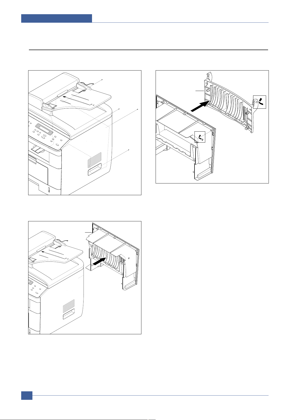
5.2 Rear Cover
1. Remove the four screws securing the Rear Cover.
2. Remove the Rear Cover from the Frame Ass'y and
Scanner Ass'y .
3. Unclip the Face Up Cover from the Rear cover, as
shown below. Then lift the Face Up Cover out.
Face Up Cover
Rear Cover
Page 3
Precautions
Service Manual
5-3
Samsung Electronics
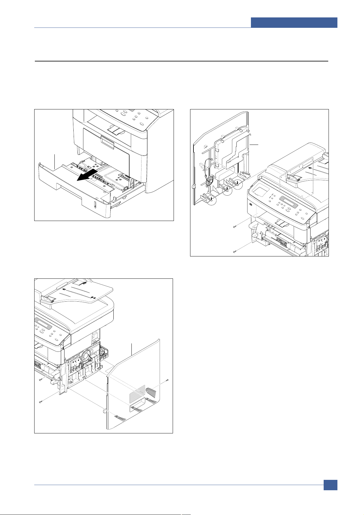
5.3 Side Cover (LH, RH)
1. Before you remove the Side Cover (LH, RH), you
should remove:
- Rear Cover (see page 5-2)
2. Take out the Cassette.
3. Open the front cover and remove 2 screws on the
front and 1 screw on the back. Release 3 clips underneath, ease the rear screw bracket over its locating
pin and pull the RH side cover to the right, taking care
not to damage the clips, to remove it from the Frame
Assembly .
Side Cover (LH)
Cassette
Side Cover (RH)
Page 4
Service Manual
Precautions
5-4
Samsung Electronics
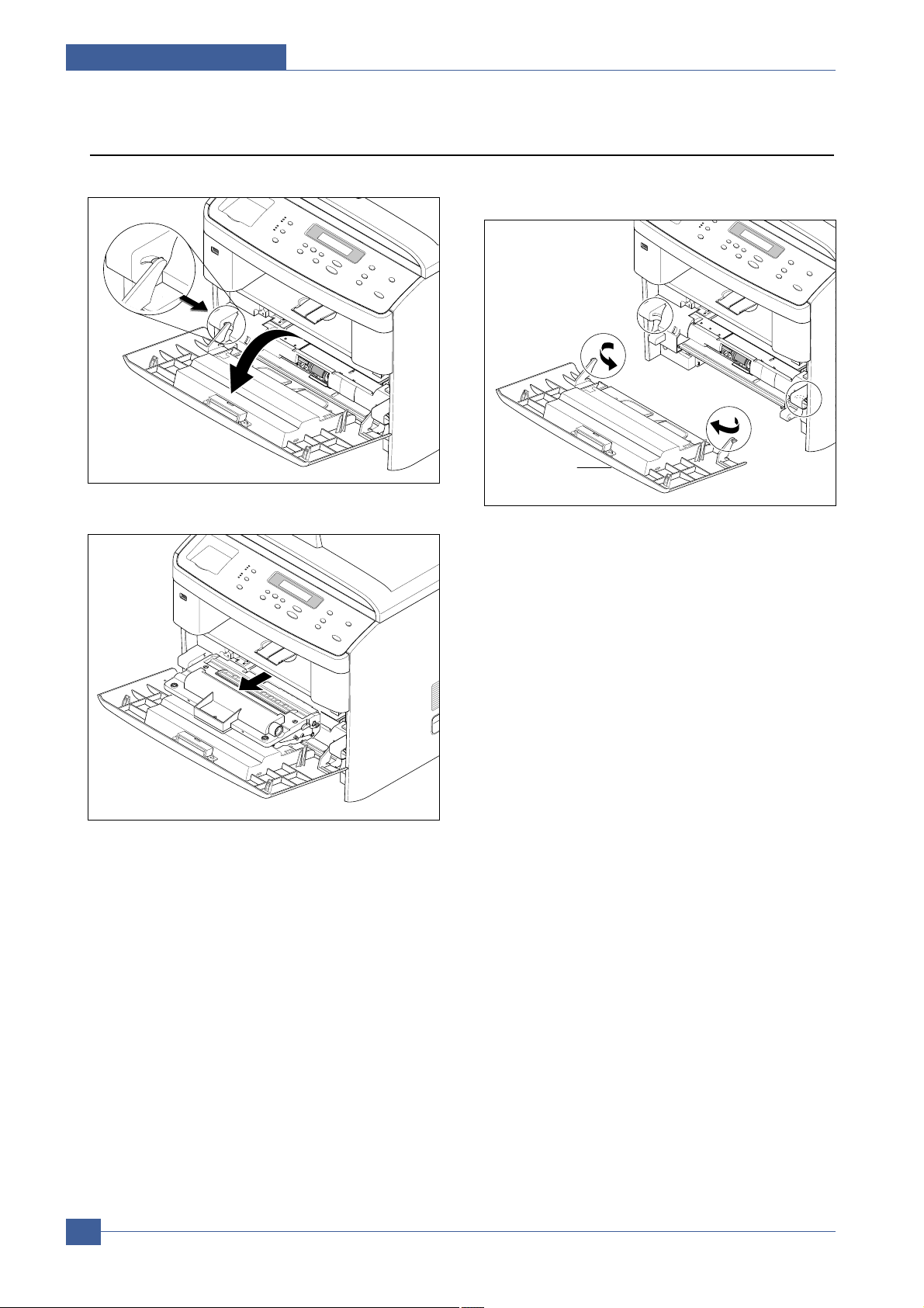
5.4 Front Cover
1. Open the Front Cover.
2. Remove the Toner Cartridge.
3. Unclip the Front Cover from the Frame Ass'y. Then
remove the Front Cover, as shown below.
Front Cover
Page 5
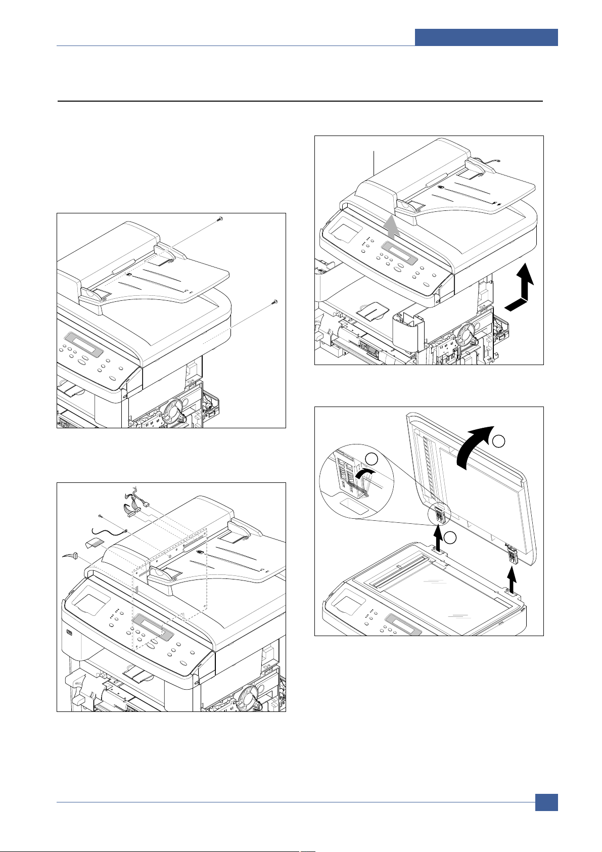
5.5 Scanner Ass'y
1. Before you remove the Scanner Ass'y, you should
remove:
- Rear Cover (see page 5-2)
- Side Cover (LH, RH) (see page 5-3)
2. Remove the 2 screws securing the Scanner Ass'y, as
shown below.
3. Remove the 5 connectors and the ground wire screw
from the main PBA as shown below.
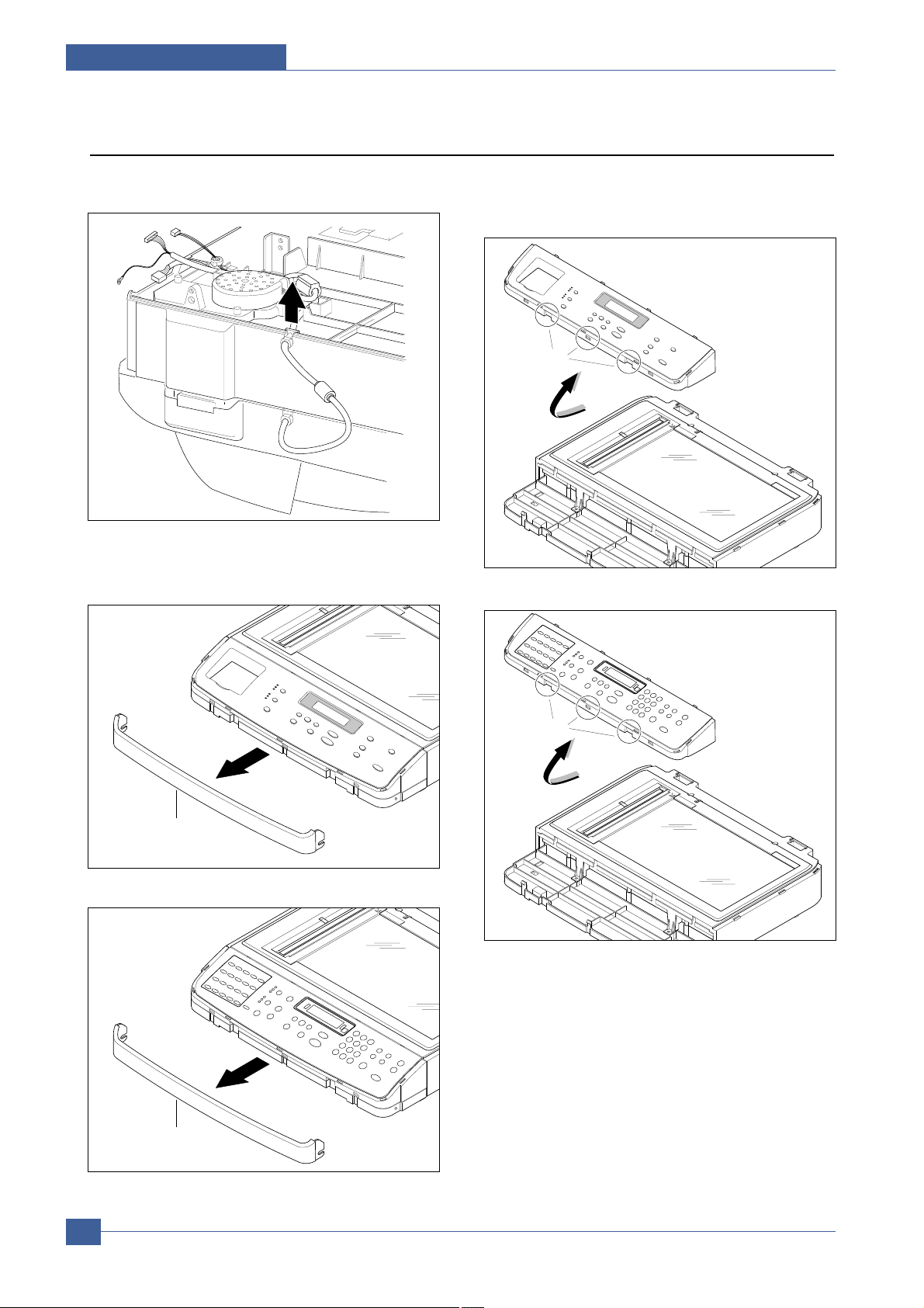
4. Pull up the Scanner Ass'y, as shown below.
5. SCX4520 only. Lift the Platen Cover upward to
remove it.
Precautions
Service Manual
5-5
Samsung Electronics
Scanner Ass'y
1
3
2
Page 6
Service Manual
Precautions
5-6
Samsung Electronics
6. SCX4720F. Free the Scanner Cable Harness from the
clips underneath the scanner and release it from the frame.
7. Lift the front part of the COVER-OPE FRONT to
release the hook connecting the cover with the scan
assembly .
<SCX-4520>
<SCX-4720F>
8. Release the 3 clips on the front of the OPE unit and
remove the OPE unit as shown below, taking care to
thread the cable harness through the frame
<SCX-4520>
<SCX-4720F>
Clips
COVER-OPE FRONT
COVER-OPE FRONT
Clips
Page 7
Precautions
Service Manual
5-7
Samsung Electronics
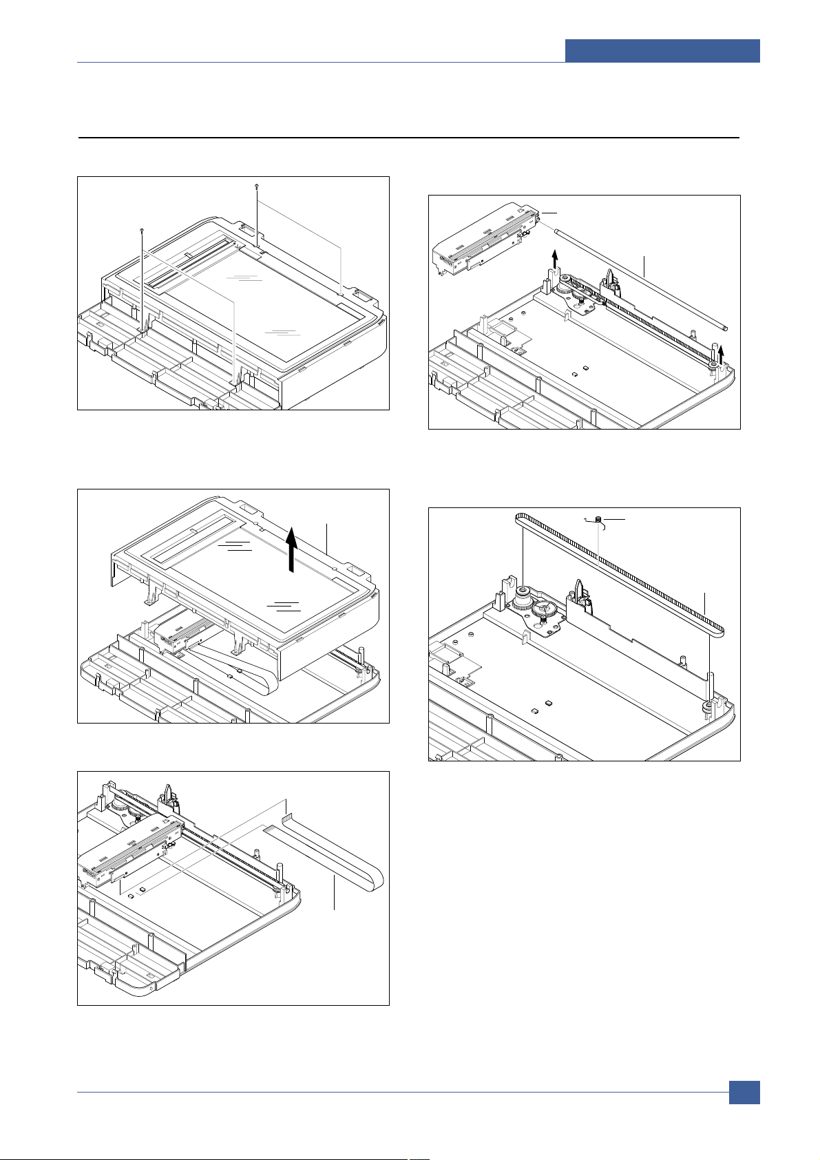
9. Remove the 4 screws securing the Scan Upper.
10. Unclip the Scan Upper from the Scan Ass'y by
releasing 2 clips on each side then pull the Scan
Upper upward and remove it.
11. Remove the CCD Cable, as shown below.
12. Pull up the CCD Shaft and take out the Scanner
Module.
13. Squeeze the spring to release the tension in the Belt
and lift from the pulleys as shown below.
CCD Cable
Scan Upper
Scanner Module
CCD Shaft
Spring
Belt
Page 8
Service Manual
Precautions
5-8
Samsung Electronics
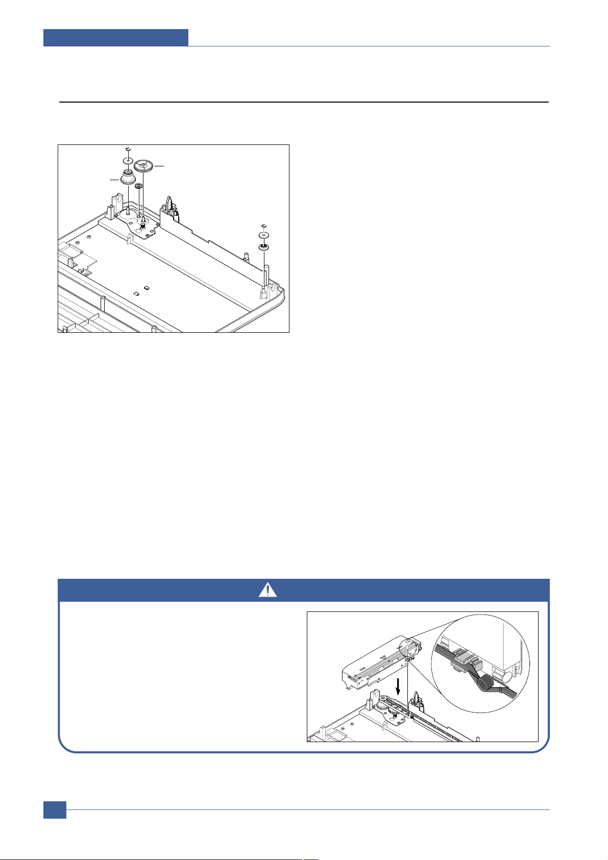
Assembling Scanner Module When
re-assembling the scanner module, belt
and belt spring take care to relocate the
tension spring as close to the right hand
side of the scanner module as is possible,
as shown on the right.
Caution
14. Remove the Reduction Gear and Idle Gear, as
shown below.
Caution. Reassembling Scanner Module
1. When re-fitting the scanner belt and belt spring
take care to relocate the tension spring as close to
the right hand side of the scanner module as is
possible, as shown on the right.
2. When refitting the Scan Upper cover take care to
ensure that the cover open switch is not trapped.
Gear-Timing
Gear-Reduction
Page 9
Precautions
Service Manual
5-9
Samsung Electronics
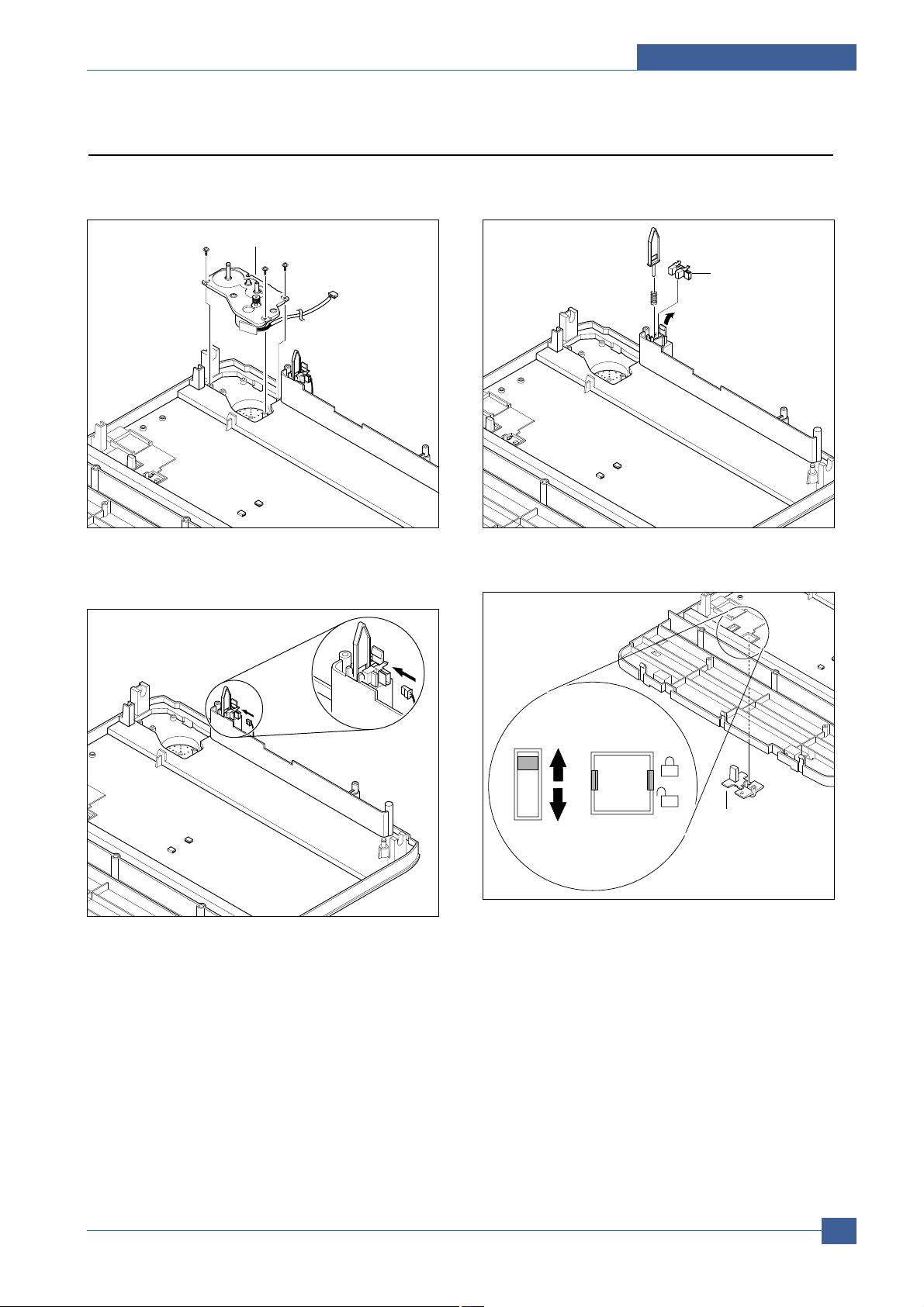
15. Remove the 3 screws and take out the Motor
Bracket.
16. Unplug the connector from the Open Sensor Ass'y.
17. Unlatch the Open Sensor and remove it, as shown
below.
18. Remove the CCD lock
Open Sensor
Motor Bracket
Unlock
CCD Lock
Lock
Page 10

Service Manual
Precautions
5-10
Samsung Electronics
5.6 ADF Motor Ass'y
1. Before you remove the ADF Motor Ass'y, you should
remove:
- Rear Cover (see page 5-2)
- Side Cover (LH, RH) (see page 5-3)
- Scanner Ass’y (see page 5-5)
2. Unclip the harness from the platen cover. Remove the
2 screws securing the ADF Ass'y and remove it, taking
care to thread the harness through the frame.
3. Remove the Open Cover, as shown below.
Caution. When working on the ADF Motor Ass’y take
care not to contaminate any of the rubber
surfaces with grease.
4. Release the Bush and rotate it until it reaches the slot,
as shown below. Then lift the Pick-Up Ass'y out.
5. Remove the 2 screws securing the Upper Cover and
remove it, as shown below.
Caution. Before removing the ADF Motor Ass’y take
great care to note the position of the ferrite
core and the motor harness routing. When
refitting the ADF Motor Ass’y ensure that the
harness and ferrite are properly located and
are clear of the motor fan and white bar clip.
ADF Ass y
Pick up Assy
Bushing
Open Cover
Upper Cover
Page 11

Precautions
Service Manual
5-11
Samsung Electronics
6. Unplug the one connector and remove 5 screws
securing the ADF Motor Ass'y. Then take out the ADF
Motor Ass'y .
Note. It is not necessary to disassemble the ADF unit in
order to change the ADF separator pad. Simply
open the ADF cover and remove the Pickup Ass’y
(step 4 page 5.10). Then, using a pair of tweezers
or a small flat-bladed screwdriver, release the clips
on each side of the ADF Separator Pad Ass’y.
ADF Lower Assy
ADF Motor Assy
Page 12

Service Manual
Precautions
5-12
Samsung Electronics
5.7 OPE Unit(SCX-4520)
1. Before you remove the OPE Unit, you should remove:
- Rear Cover (see page 5-2)
- Side Cover (LH, RH) (see page 5-3)
- Scanner Ass’y (see page 5-5)
2. Remove the 7 screws securing the OPE PBAfrom to
the OPE Cover.
3. Remove the Contact Rubber from the OPE Cover.
4. Remove the Key Pad from the OPE Cover.
OPE Cover
OPE PBA
Key Pad
Contact Rubber
Page 13

Precautions
Service Manual
5-13
Samsung Electronics
OPE Unit(SCX-4720F)
1. Before you remove the OPE Unit, you should remove:
- Rear Cover (see page 5-2)
- Side Cover (LH, RH) (see page 5-3)
- Scanner Ass’y (see page 5-5)
2. Remove the 10 screws securing the OPE PBAfrom to
the OPE Cover.
3. Remove the Contact Rubber from the OPE Cover.
4. Remove the Key Pad from the OPE Cover.
OPE Cover
OPE PBA
Key Pad
Contact Rubber
Page 14

Service Manual
Precautions
5-14
Samsung Electronics
5.8 Middle Cover & Exit Roller
1. Before you remove the Middle Cover and Exit Roller,
you should remove:
- Rear Cover (see page 5-2)
- Side Cover (LH, RH) (see page 5-3)
- Scanner Ass'y (see page 5-5)
2. Remove the 4 screws securing the Middle Cover and
remove it.
3. Remove 2 screws securing the Controller Shield Ass’y
to the Middle Cover. Unclip the Middle Cover from the
Frame Ass'y, as shown below. Take care to release
the Shield Ass’y locating pegs and lift the Top Cover out.
4. Remove the Exit Gear and Bearing, as shown below.
Middle Cover
Page 15

Precautions
Service Manual
5-15
Samsung Electronics
1. Before you remove the Main PBA, you should
remove:
- Rear Cover (see page 5-2)
- Side Cover(LH, RH) (see page 5-3)
2. Remove all of the connectors and the 5 screws connecting the Controller Shield Assembly to the Middle
Cover and frame and remove the assembly.
3. If fitted remove the 2 screws connecting the NIC card
to the Controller Shield Assembly and remove the card.
4. Remove 3 screws to remove the bracket from the
main board.
Controller Shield Assy
5.9 Controller Shield Ass’y
Main Board
Bracket
NIC Card
Page 16

Service Manual
Precautions
5-16
Samsung Electronics
1. Before you remove the Engine Shield Ass'y, you
should remove:
- Rear Cover (see page 5-2)
- Side Cover(LH, RH) (see page 5-3)
- Scanner (see page 5-5)
2. Unplug the Exit, AC and Fan connectors. Unplug the
LIU connector if fitted.
3. Remove the 11 screws securing the Engine Shield
Ass'y and tilt to one side. Then unplug the all the
HVPS/SMPS harness before removing the ass’y.
4. Remove the 2 screws to remove the exit board.
Engine shild Assy
5.10 Engine Shield Ass’y & Exit Board
Main Connector
Exit Connector
AC Connector
Fan Connector
Exit Board
Page 17

Precautions
Service Manual
5-17
Samsung Electronics
5.11 SMPS and LIU
1. Before you remove the SMPS, you should remove:
- Rear Cover (see page 5-2)
- Side Cover(LH, RH) (see page 5-3)
- Scanner Ass’y (see page 5-5)
- Engine Shield Ass’y(see page 5-16)
2. Remove the 2 screws securing the Inlet Bracket and
remove it
3. Remove the one screw securing the Engine Shield
ground wire
4. Remove the 3 screws securing the SMPS. Then lift
the SMPS out, as shown below.
5. Remove the 3 screws securing the LIU. Then lift the
LIU out, as shown below.
Inlet Bracket
SMPS
Page 18

Service Manual
Precautions
5-18
Samsung Electronics
5.12 Fuser Ass'y
1. Before you remove the Fuser Ass'y, you should
remove:
- Rear Cover (see page 5-2)
2. Unplug the two connectors from the Main PBAand
SMPS, as shown below. Then remove the 4 screws
securing the Fuser Ass'y and remove it.
3. Remove the 2 bolts securing the Thermostat. Then lift
the Thermostat out taking care not to loose the 2 nuts.
4. Remove the 2 screws securing the Halogen Lamp.
Then take out the Halogen Lamp from the Heat Roller
5. Remove 4 screws to remove the fuser cover as
below. Remove 2 screws to remove the guide input.
Fuser Ass y
Heat Roller
Halogen Lamp
Bolts
Thermostat
Nuts
Claw
Fuser Cover
guide Input
Page 19

Precautions
Service Manual
5-19
Samsung Electronics
6. Unwrap the Thermistor Harness, as shown below. 7. Remove the one screw securing the Thermister and
remove it, as shown below.
Thermistor
5.13 Fan
1. Before you remove the Fan, you should remove:
- Rear Cover (see page 5-2)
- Side Cover (RH) (see page 5-3)
2. Unplug the connector from the SMPS and remove the
one screw. Then take out the Fan.
DC Fan
Thermistor
Page 20

Service Manual
Precautions
5-20
Samsung Electronics
1. Before you remove the LSU, you should remove:
- Rear Cover (see page 5-2)
- Side Cover (LH, RH) (see page 5-3)
- Scanner Ass’y (see page 5-5)
- Front Cover (see page 5-4)
- Middle Cover (see page 5-14)
2. Remove the 4 screws securing the LSU and remove it.
3. Unplug the two connectors.
5.14 LSU
1. Before you remove the CRUM Board, you should
remove:
- Rear Cover (see page 5-2)
- Side Cover (LH, RH) (see page 5-3)
- Scanner Ass’y (see page 5-5)
- Front Cover (see page 5-4)
- Middle Cover (see page 5-14)
- LSU (see page 5-20)
2. Remove the 4 screws to separate the CRUM board
from the main frame as below, taking care not to loose
the springs.
5.15 CRUM Board
CRUM Board
Page 21

Precautions
Service Manual
5-21
Samsung Electronics
5.16 Drive Ass'y
1. Before you remove the Drive Ass'y, you should
remove:
- Rear Cover (see page 5-2)
- Side Cover (LH) (see page 5-3)
- Shield Controller Ass’y (see page 5-9)
2. Remove the 5 screws securing the Drive Ass'y.
3. Take out the Drive Ass'y, then unplug the connector
from the Motor PBA, as shown below.
Caution. The six screws have numbers stamped. into
the Drive Ass’y base plate. When refitting the
Drive Ass’y tighten the screws the order they
are numbered. Only screw s numbered 1 to 5
are fitted at this stage. Screw 6 is fitted when
the Shield Controller Ass’y is refitted
5.17 Cover Mid Front
1. Before you remove the Cover Mid Front, you should
remove:
- Rear Cover (see page 5-2)
- Side Cover (LH, RH) (see page 5-3)
- Middle Cover (see page 5-14)
2. Remove the 4 screws securing the Cover Mid Front
and release 2 clips in the center. This cover is fragile
take care when removing it.
Drive Ass y
Drive Ass y
clips
Cover Mid Front
Page 22
Service Manual
Precautions
5-22
Samsung Electronics
1. Before you remove the Transfer Ass'y, you should
remove:
- Rear Cover (see page 5-2)
- Side Cover (LH, RH) (see page 5-3)
- Scanner Ass’y (see page 5-5)
- Front Cover (see page 5-4)
- Middle Cover (see page 5-14)
- LSU (see page 5-20)
- Cover Mid Front (see page 5-22)
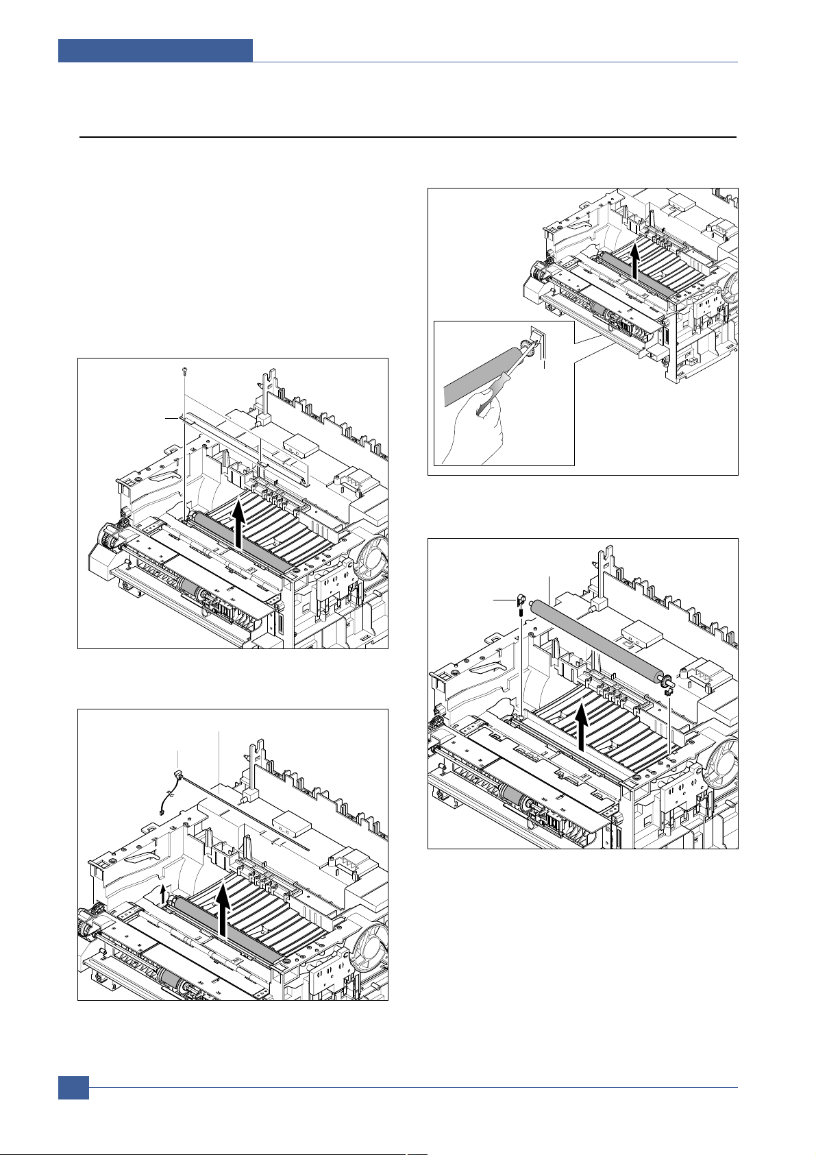
2. Remove the 3 screws securing the Transfer Earth and
remove it.
3. Unplug the PTL Holder connector, then remove the
PTL Holder and PTL Lens, as shown below.
4. Remove the transfer roller by pressing the hook
securing the roller to the right using a tool.
5. Unlatch the Bushing and remove it. Then lift the
Transfer Roller out, as shown below.
Transfer Earth
5.18 Transfer Ass'y
Hook
Transfer Roller
Bushing
PTL Lens
PTL Holder
Page 23

Precautions
Service Manual
5-23
Samsung Electronics
5.19 Feed Ass'y
1. Before you remove the Feed Ass'y, you should
remove:
- Rear Cover (see page 5-2)
- Side Cover (LH, RH) (see page 5-3)
- Front Cover (see page 5-4)
- Scanner Ass’y (see page 5-5)
- Middle Cover (see page 5-14)
- Controller Shield Ass’y (see page 5-15)
- Drive Ass’y (see page 5-20)
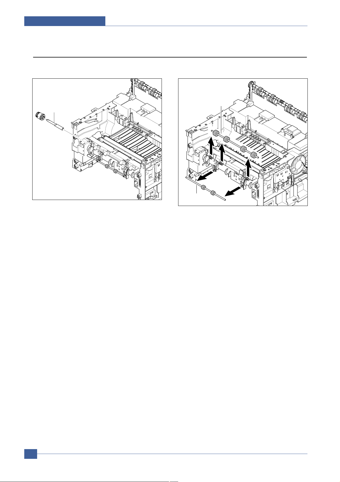
2. Remove the 4 screws securing the Guide Paper Front
and remove it.
3. Remove the screws on the right and left sides of the
guide paper to remove the guides and the spring as
shown below.
4. Remove the 3 screws securing the Feed Bracket and
remove it.
5. Remove the Feed Gear2.
Guide Paper Front
Feed Bracket
Screw
Spring
Guide Paper
Feed Gear2
Page 24
Service Manual
Precautions
5-24
Samsung Electronics
6. Remove the Feed Gear1 Ass'y. 7. Pull up the Feed Roller and Feed Roller1.
Feed Gear1 Assy
Feed Roller
Feed Roller1
Page 25
Precautions
Service Manual
5-25
Samsung Electronics
5.20 Pick-Up Ass'y & Solenoid
1. Before you remove the Pick-Up Ass'y, you should
remove:
- Rear Cover (see page 5-2)
- Side Cover (LH, RH) (see page 5-3)
- Front Cover (see page 5-4)
- Scanner Ass’y (see page 5-5)
- Middle Cover (see page 5-14)
- Controller Shield Ass,y (see page 5-15)
- Engine Shield Ass,y (see page 5-16)
- Drive Ass'y (see page 5-20)
- Feed Ass’y (see page 5-23)
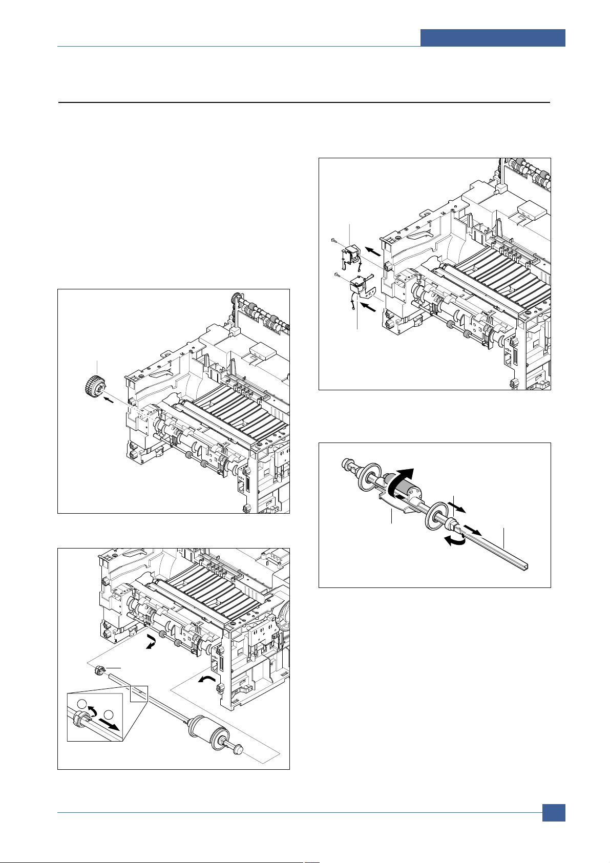
2. Remove the Pick-Up Gear Ass,y.
3. Take out the Pick-Up Ass'y, as shown below.
4. Remove the 2 screws securing the Manual Solenoid
and Pick-Up Solenoid. Then remove Manual Solenoid
and Pick-Up Solenoid.
5. To replace the pick up roller, move the stopper securing the sponge-roller to the right and then turn the
sponge-roller to remove it from the shaft.
When replacing either the MP pick up roller or main
cassette pick up roller only, it is possible to do this by
turning the set over after removing the cassette and
the processor. See page 5-26
Pick up Gear Assy
Pick Up Solenoid
Manual Solenoid
Stopper
Sponge Roller
Shaft
Bush
1
2
Page 26

Service Manual
Precautions
5-26
Samsung Electronics
6. It is a simple matter to replace the MP Pickup
Roller and the main cassette Pickup Roller
without dismantling the set.
In both cases first remove the main paper
cassette, toner cartridge and front cover.
a) In order to replace the main cassette Pickup
Roller
1) Turn the set upside down
2) Release the white catch and slide the locking
piece as far to the side as possible.
3) Slide the white collar as far to the side as
possible.
4) Slide the Pickup Roller as far as possible to
the side, until it is free from the white collar on
the other end.
5) Rotate the Pickup Roller around the drive
shaft until it can be removed.
b) In order to replace the MP Pickup Roller
1) Release the white catch and slide the locking
piece as far to the side as possible.
2) Slide the white collar as far to the side as
possible.
3) Slide the Pickup Roller as far as possible to
the side, until it is free from the white collar on
the other end.
4) Rotate the Pickup Roller around the drive
shaft until it can be removed.
 Loading...