

Page 1
DIGITAL LASER MFP
SCX-4521F Series
SCX-4321/XEV
Basic Model :SCX-4521F
Manual
SERVICE
DIGITAL LASER MFP The keynote of Product
- Machine Life: 50,000Pages
- Cpu: Chorus2
- Device Memory: 16MB
- Resolution: 600*600dpi
- Option: N/A
- Printing Speed: 22ppm/LTR,20ppm/A4
- Print Memory: 10MB
- Print Language: SPL
- Path Type: C-Path
- Cassette Capa.: 150sheets
- Outlet Stacking Capa.: 50sheets
- Toner Cartridge: initial(1K), sales(3K)
- ADF Capacity: 30sheets
- Scan Method: 600 dpi Color CIS
- Copy Speed: SDMC: 22Cpm/Ltr,
SCX-4521F Series
- Interface: USB1.1, IEEE1284
MDMC: 7Cpm/Ltr
Page 2

ELECTRONICS
* This service manual is a property of Samsung Electronics Co., Ltd.
Any unauthorized use of Manual can be punished under applicable
international and/or domestic law.
* This service manual is also provided on the web, the ITSELF
system Samsung Electronics Co., Ltd.
http://itself.sec.samsung.co.kr
Samsung Electronics Co.,Ltd. Aug. 2005
Printed in Korea.
VERSION NO. : 1.00 CODE : JC-0139H
Page 3

Contents
1. Precautions
1.1 Safety Warning 1-1
1.2 Safety Caution 1-2
1.3 ESD Precautions 1-4
2. Product Specification
2.1 Product Overview 2-1
2.2 Specifications 2-1
2.3 Model Comparison Table 2-5
3. System Overview
3.1 System Outline 3-1
3.2 H/W Structure and Descriptions 3-7
3.3 S/W Structure and Descriptions 3-19
3.4 Initial Product Installation 3-24
4. Alignment and Adjustments
4.1 Sample Pattern 4-1
4.2 Control Panel 4-2
4.3 Consumables and Replacement Parts 4-4
4.4 LED Status Error Messages 4-4
4.5 Periodic Defective Image 4-5
4.6 How to use DCU 4-6
4.7 Paper Path 4-11
Page 4

Continued
5. Disassembly and Reassembly
5.1 General Precautions on Disassembly 5-1
5.2 Disassembly and Reassembly 5-2
6. Troubleshooting
6.1 Checking Symptoms 6-1
6.2 Bad discharge 6-4
6.3 Malfunction 6-8
6.4 Bad software environment 6-13
6.5 Bad Image 6-17
7. Exploded Views & Parts List
7.1 Exploded Views and Parts List 7-1
8. Block diagram
8.1 System Block Diagram 8-1
8.2 System Timing Chart 8-2
9. Connection Diagram
9.1 Connection Diagram 9-1
10. Schematic Diagram
10.1 Main Board 10-1
10.2 Connector Circuit Diagram 10-5
10.3 SMPS Circuit Diagram 10-6
10.4 HVPS Circuit Diagram 10-7
Page 5

Continued
11. Reference Information
11.1 Troubleshooting Tools 11-1
11.2 Acronyms and Abbreviations 11-2
11.3 Selecting printer locations 11-4
11.4 Sample Tests Patterns 11-5
12. Circuit Description
12.1 Engine Controller 12-1
Page 6
Precautions
Samsung Electronics
Service Manual
1-1
1
1
1. Precautions
In order to prevent accidents and to prevent damage to the equipment please read the precautions listed
below carefully before servicing the printer and follow them closely.
1.1 Safety Warning
(1) Only to be serviced by appropriately qualified service engineers.
High voltages and lasers inside this product are dangerous. This printer should only be serviced by a suitably
trained and qualified service engineer.
(2) Use only Samsung replacement parts
There are no user serviceable parts inside the printer. Do not make any unauthorized changes or
additions to the printer, these could cause the printer to malfunction and create electric shock or fire hazards.
(3) Laser Safety Statement
The Printer is certified in the U.S. to conform to the requirements of DHHS 21 CFR, chapter 1 Subchapter J for
Class 1(1) laser products, and elsewhere, it is certified as a Class I laser product
conforming to the requirements of IEC 825. Class I laser products are not considered to be hazardous. The
laser system and printer are designed so there is never any human access to laser radiation above a Class I
level during normal operation, user maintenance, or prescribed service condition.
Warning >> Never operate or service the printer with the protective cover removed from Laser/Scanner assembly. The
reflected beam, although invisible, can damage your eyes. When using this product, these basic safety
pre-cautions should always be followed to reduce risk of fire, electric shock, and injury to persons.
CAUTION - INVISIBLE LASER RADIATION
WHEN THIS COVER OPEN.
DO NOT OPEN THIS COVER.
VORSICHT - UNSICHTBARE LASERSTRAHLUNG,
WENN ABDECKUNG GE FFNET .
NICHT DEM STRAHL AUSSETZEN.
ATTENTION - RAYONNEMENT LASER INVISIBLE EN CAS
D OUVERTURE. EXPOSITION DANGEREUSE
AU FAISCEAU.
ATTENZIONE - RADIAZIONE LASER INVISIBILE IN CASO DI
APERTURA. EVITARE L ESPOSIZIONE AL
FASCIO.
PRECAUCION - RADIACION LASER IVISIBLE CUANDO SE ABRE.
EVITAR EXPONERSE AL RAYO.
ADVARSEL. - USYNLIG LASERSTR LNING VED BNING, NR
SIKKERHEDSBRYDERE ER UDE AF FUNKTION.
UNDG UDSAETTELSE FOR STR LNING.
ADVARSEL. - USYNLIG LASERSTR LNING N R DEKSEL
PNES. STIRR IKKE INN I STR LEN.
UNNG EKSPONERING FOR STR LEN.
VARNING - OSYNLIG LASERSTR LNING N R DENNA DEL
R PPNAD OCH SP RREN R URKOPPLAD.
BETRAKTA EJ STR LEN. STR LEN R FARLIG.
VARO! - AVATTAESSA JA SUOJALUKITUS OHITETTAESSA
OLET ALTTIINA N KYM TT M LLE LASERS TEILYLLE L KATSO STEESEEN.
Page 7

Samsung Electronics
Service Manual
Precautions
1-2
1.2 Caution for safety
1.2.1 Toxic material
This product contains toxic materials that could cause illness if ingested.
(1) If the LCD control panel is damaged it is possible for the liquid inside to leak. This liquid is toxic. Contact with the skin
should be avoided, wash any splashes from eyes or skin immediately and contact your doctor. If the liquid gets into
the mouth or is swallowed see a doctor immediately.
(2) Please keep toner cartridges away from children. The toner powder contained in the toner cartridge may be harmful
and if swallowed you should contact a doctor.
1.2.2 Electric Shock and Fire Safety Precautions
Failure to follow the following instructions could cause electric shock or potentially cause a fire.
(1) Use only the correct voltage, failure to do so could damage the printer and potentially cause a fire or electric
shock.
(2) Use only the power cable supplied with the printer. Use of an incorrectly specified cable could cause the cable
to overheat and potentially cause a fire.
(3) Do not overload the power socket, this could lead to overheating of the cables inside the wall and could lead to
a fire.
(4) Do not allow water or other liquids to spill into the printer, this can cause electric shock. Do not allow paper
clips, pins or other foreign objects to fall into the printer these could cause a short circuit leading to an electric
shock or fire hazard..
(5) Never touch the plugs on either end of the power cable with wet hands, this can cause electric shock. When
servicing the printer remove the power plug from the wall socket.
(6) Use caution when inserting or removing the power connector. The power connector must be inserted com-
pletely otherwise a poor contact could cause overheating possibly leading to a fire. When removing the power
connector grip it firmly and pull.
(7) Take care of the power cable. Do not allow it to become twisted, bent sharply round corners or otherwise
damaged. Do not place objects on top of the power cable. If the power cable is damaged it could overheat and
cause a fire or exposed cables could cause an electric shock. Replace a damaged power cable immediately,
do not reuse or repair the damaged cable. Some chemicals can attack the coating on the power cable,
weakening the cover or exposing cables causing fire and shock risks.
(8) Ensure that the power sockets and plugs are not cracked or broken in any way. Any such defects should be
repaired immediately. Take care not to cut or damage the power cable or plugs when moving the machine.
(9) Use caution during thunder or lightening storms. Samsung recommend that this machine be disconnected from
the power source when such weather conditions are expected. Do not touch the machine or the power cord if it
is still connected to the wall socket in these weather conditions.
(10) Avoid damp or dusty areas, install the printer in a clean well ventilated location. Do not position the machine
near a humidifier. Damp and dust build up inside the machine can lead to overheating and cause a fire.
(11) Do not position the printer in direct sunlight. This will cause the temperature inside the printer to rise possibly
leading to the printer failing to work properly and in extreme conditions could lead to a fire.
(12) Do not insert any metal objects into the machine through the ventilator fan or other part of the casing, it could
make contact with a high voltage conductor inside the machine and cause an electric shock.
Page 8

Precautions
Samsung Electronics
Service Manual
1-3
1.2.3 Handling Precautions
The following instructions are for your own personal safety, to avoid injury and so as not to damage the printer
(1) Ensure the printer is installed on a level surface, capable of supporting its weight. Failure to do so could cause
the printer to tip or fall.
(2) The printer contains many rollers, gears and fans. Take great care to ensure that you do not catch your fingers,
hair or clothing in any of these rotating devices.
(3) Do not place any small metal objects, containers of water, chemicals or other liquids close to the printer which if
spilled could get into the machine and cause damage or a shock or fire hazard.
(4) Do not install the machine in areas with high dust or moisture levels, beside on open window or close to a
humidifier or heater. Damage could be caused to the printer in such areas.
(5) Do not place candles, burning cigarettes, etc. on the printer, these could cause a fire.
1.2.4 Assembly / Disassembly Precautions
Replace parts carefully, always use Samsung parts. Take care to note the exact location of parts and also
cable routing before dismantling any part of the machine. Ensure all parts and cables are replaced correctly.
Please carry out the following procedures before dismantling the printer or replacing any parts.
(1) Check the contents of the machine memory and make a note of any user settings. These will be erased if the
mainboard is replaced.
(2) Ensure that power is disconnected before servicing or replacing any electrical parts.
(3) Disconnect printer interface cables and power cables.
(4) Only use approved spare parts. Ensure that part number, product name, any voltage, current or temperature
rating are correct.
(5) When removing or re-fitting any parts do not use excessive force, especially when fitting screws into plastic.
(6) Take care not to drop any small parts into the machine.
(7) Handling of the OPC Drum
- The OPC Drum can be irreparably damaged if it exposed to light.
Take care not to expose the OPC Drum either to direct sunlight or to fluorescent or incandescent room
lighting. Exposure for as little as 5 mins can damage the surface’s photoconductive properties and will result
in print quality degradation. Take extra care when servicing the printer. Remove the OPC Drum and store it in
a black bag or other lightproof container. Take care when working with the covers(especially the top cover)
open as light is admitted to the OPC area and can damage the OPC Drum.
- Take care not to scratch the green surface of OPC Drum Unit.
If the green surface of the Drum Cartridge is scratched or touched the print quality will be compromised.
Page 9
Samsung Electronics
Service Manual
Precautions
1-4
1.2.5 Disregarding this warning may cause bodily injury
(1) Be careful with the high temperature part.
The fuser unit works at a high temperature. Use caution when working on the printer. Wait for the fuser to cool
down before disassembly.
(2) Do not put finger or hair into the rotating parts.
When operating a printer, do not put hand or hair into the rotating parts (Paper feeding entrance, motor, fan,
etc.). If do, you can get harm.
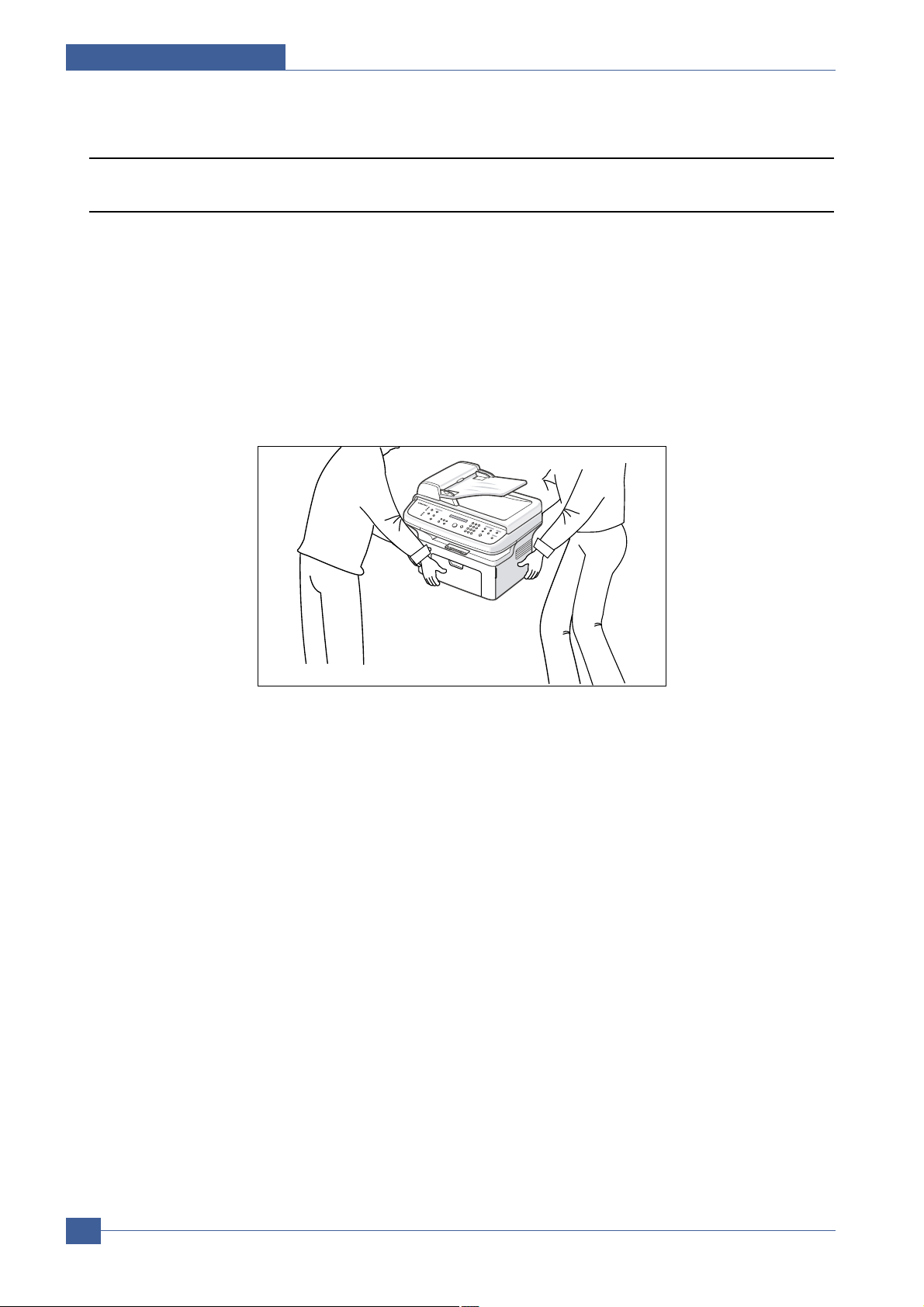
(3) When you move the printer.
This printer weighs 10.4kg including toner cartridge and cassette. Use safe lifting and handling techniques.
Back injury could be caused if you do not lift carefully.
(4) Ensure the printer is installed safely.
The printer weighs 10.4Kg, ensure the printer is installed on a level surface, capable of supporting its weight.
Failure to do so could cause the printer to tip or fall possibly causing personal injury or damaging the printer.
(5) Do not install the printer on a sloping or unstable surface. After installation, double check that the printer is stable.
Page 10

Precautions
Samsung Electronics
Service Manual
1-5
1.3 ESD Precautions
Certain semiconductor devices can be easily damaged by static electricity. Such components are commonly called
“Electrostatically Sensitive (ES) Devices”, or ESDs. Examples of typical ESDs are: integrated circuits, some field
effect transistors, and semiconductor “chip” components.
The techniques outlined below should be followed to help reduce the incidence of component damage caused by
static electricity.
Caution >>Be sure no power is applied to the chassis or circuit, and observe all other safety precautions.
1. Immediately before handling a semiconductor component or semiconductor-equipped assembly, drain off any
electrostatic charge on your body by touching a known earth ground. Alternatively, employ a commercially available wrist strap device, which should be removed for your personal safety reasons prior to applying power to the
unit under test.
2. After removing an electrical assembly equipped with ESDs, place the assembly on a conductive surface, such as
aluminum or copper foil, or conductive foam, to prevent electrostatic charge buildup in the vicinity of the assembly .
3. Use only a grounded tip soldering iron to solder or desolder ESDs.
4. Use only an “anti-static” solder removal device. Some solder removal devices not classified as “anti-static” can
generate electrical charges sufficient to damage ESDs.
5. Do not use Freon-propelled chemicals. When sprayed, these can generate electrical charges sufficient to damage ESDs.
6. Do not remove a replacement ESD from its protective packaging until immediately before installing it. Most
replacement ESDs are packaged with all leads shorted together by conductive foam, aluminum foil, or a comparable conductive material.
7. Immediately before removing the protective shorting material from the leads of a replacement ESD, touch the protective material to the chassis or circuit assembly into which the device will be installed.
8. Maintain continuous electrical contact between the ESD and the assembly into which it will be installed, until completely plugged or soldered into the circuit.
9. Minimize bodily motions when handling unpackaged replacement ESDs. Normal motions, such as the brushing
together of clothing fabric and lifting one’s foot from a carpeted floor, can generate static electricity sufficient to
damage an ESD.
1. Exercise caution when replacing a super capacitor
or Lithium battery. There could be a danger of
explosion and subsequent operator injury and/or
equipment damage if incorrectly installed.
2. Be sure to replace the battery with the same or
equivalent type recommended by the manufacturer.
3. Super capacitor or Lithium batteries contain toxic
substances and should not be opened, crushed, or
burned for disposal.
4. Dispose of used batteries according to the
manufacture’s instructions.
1.4 Super Capacitor or Lithium Battery Precautions
Page 11

Product Specifications
Samsung Electronics
Service Manual
2-1
2
2
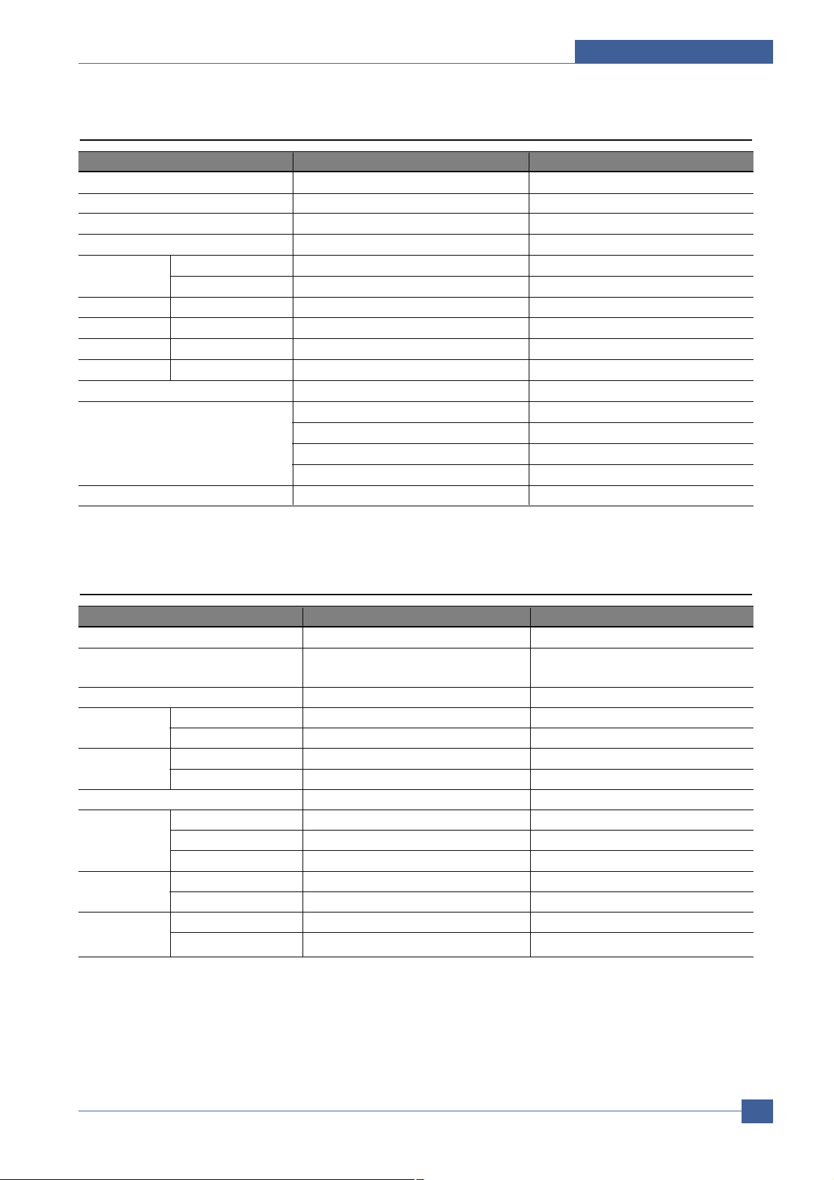
Item Descriptions Remark
Basic Model SCX-4521F(4-in-1 Flatbed MFP)
SCX-4321(3-in-1 Flatbed MFP)
Target User SOHO, Economical(Speed/Price) Customer
Customer Benefits - Compact Size
(Sales Points) - 22ppm/A4, 22ppm/Letter fastest speed in its price class
- Favorite Copy
- ID Card Copy
- Toner Save
Key Specification - up to 22ppm/A4(Up to 22ppm/Letter)
- 150 sheets Multi-Purpose type paper input/50 sheets Paper Output
- 3,000pages toner capacity
- 600dpi Print/Copy Resoulusion
- Samsung Print Language
- 16MB System memory
- 30 ADF
- 33.6 Kbps Fax Modem
- 100 Speed Dial
- 72 Hour Battery Back-up
2. Product Specifications
2.1 Product Overview
Page 12

Samsung Electronics
Service Manual
Product Specifications
2-2
2.2 Specifications
Product Specifications are subject to change without notice. See below for product specifications.
2.2.1 General Specifications
Item Descriptions (SCX-4321 / SCX-4521F)
Major Features Copier, Print, Scan, Fax(SCX-4521F)
Net Dimension (WxDxH) 438(W)*374(D)*368(H)(17.2x14.7x14.5")
Net Weight(Inc. Toner Cartridge) 10.4kg
CPU Chorus-2 (66MHz)
LCD 2 Line x 16 characters / 2Line x 8 characters(for china and korea)
Toner Save Yes (With toner save button)
I/O Interface USB1.1 (Compatible with USB 2.0), IEEE 1284 Parallel
Network Interface No
OS Compatibility Windows 98/Me/NT4.0/2000/XP, Various Linux OS (via USB interface only) including
Red Hat 8.0~9.0, Fedora core 1~3, Mandrake 9.0~10.2, and SuSe 8.2~9.2, Mac 10.3
Power Requirement 110 ~ 127 VAC, 50/60 Hz, 4.5A
220 ~ 240 VAC, 50/60 Hz, 2.5A
Power Consumption Sleep Mode : Under 10 W
Standby Mode : 65W
Average : 350 W (Print Mode)
Energy Star Compliant Yes
Power Switch Yes
Noise Warm up 49 dBA
Stand by 35 dBA
Coping 55 dBA
Printing 53dBA
Warm up time from Power On Status Less than 35 seconds
from Sleep Mode Less than 30 seconds
(Recovery time)
Max. Monthly Print 4,200 pages
Volume Scan ADF: 2,500 pages, PLATEN: 1,700 pages
Average Monthly Print Volume 400 pages
Average Monthly SCAN Volume 150 pages
Machine Life ENGINE 5 years or 50,000 Pages. Whichever comes first
SCANNER ADF : 30,000 Pages, Platen : 20,000 Pages
Operation Temperature 10°C ~ 32 °C (50°F ~ 89°F)
conditions Humidity 20 % ~ 80 % RH
Approval Class B
Device Memory 16MB
Page Counter Yes
Print Configuration Sheet(System Data) Yes
Page 13
Items SCX-4321 SCX-4521F
Method Laser Beam Printing Laser Beam Printing
Speed Up to
22ppm
in A4 (
22ppm
in Letter) Up to
22ppm
in A4 (
22ppm
in Letter)
Emulation SPL SPL
Power Save Yes
(Interval option: 5, 10,15, 30, 45 minute)
Yes
(Interval option: 5, 10,15, 30, 45 minute)
Resolution Normal 600 x 600 dpi 600 x 600 dpi
RET - Memory 10MB 10MB
First Print Out From Stand by Approx. 11 seconds Approx. 11 seconds
Time From Cold Status Less than 41 seconds Less than 41 seconds
Duplex Print - WHQL Compliant Window XP Window XP
Printable Area A4: 201.6x288.6mm A4: 201.6x288.6mm
LTR: 207.6x270.6mm LTR: 207.6x270.6mm
Legal: 207.6x347.6mm Legal: 207.6x347.6mm
Folio: 207.6x322.6mm Folio: 207.6x322.6mm
Halftone (Gray Scale) 256 levels 256 levels
Product Specifications
Samsung Electronics
Service Manual
2-3
2.2.2 Print Specifications
Items SCX-4321 SCX-4521F
Compatibility
Twain standard / WIA Standard (Window 2000/XP) Twain standard / WIA Standard (Window 2000/XP)
Scan Method
600dpi Color CIS(Contact Image Sensor) 600dpi Color CIS(Contact Image Sensor)
Module Module
PC Scan Speed Lineart, Halftone 10sec Platen(13sec ADF) 10sec Platen(13sec ADF)
through Platen Gray 23sec Platen (26sec ADF) 23sec Platen (26sec ADF)
Color 300dpi 65sec Platen(70sec ADF) 65sec Platen(70sec ADF)
Resolution Optical 600 x 600 dpi 600 x 600 dpi
Enhanced 4800 x 4800 dpi 4800 x 4800 dpi
Halftone 256 levels 256 levels
Scan Size Max. Document Width Max.216mm (8.5") Max.216mm (8.5")
Effective Scan Length 297 mm (11.7") 297 mm (11.7")
Effective Scan Width Letter/Legal: 208mm(8.2")A4: 202mm Letter/Legal: 208mm(8.2")A4: 202mm
Scan-to Button Yes Yes
Application Yes Yes
Scan Depth Color 24 bit 24 bit
Mono
1bit for Line art, Halftone, 8 Bit for Gray scale 1bit for Line art, Halftone, 8 Bit for Gray scale
2.2.3 Scan Specifications
Page 14
Samsung Electronics
Service Manual
Product Specifications
2-4
2.2.4 Copy Specifications
Item Descriptions (SCX-4321 / SCX-4521F)
Copy Speed Up to 22ppm in A4 (22ppm in Letter)
Resolution Optical 600*600 dpi (Scan:600*600dpi, Print: 600*600dpi)
- Text & Text/Photo mode : 600*300dpi(ADF, Platen)
- Photo mode : 600*600dpi (Platen), 600*300dpi(ADF)
Enhanced - First Copy Stand by Approx. 16 seconds(ADF), Approx. 11 seconds(Platen)
Out Time From Power Save Mode Approx. 46 seconds(ADF), Approx. 40 seconds(Platen)
(110V only)
Original Image type selection Text, Text/Photo, Photo
Zoom Range 25-400%(Platen), 25-100%(ADF)
Multi Copy 1~99 Pages
Preset [Original(100%)], [A4
A5(71%)], [LGL LTR(78%)], [LGL 4(83%)],
[A4
LTR(94%)], [EXE LTR(104%)], [A5 A4(141%)], 25%, 50%, 150%
200%, 400%, [Custom: 25-400%)]
Darkness Control 3 level (Light, Normal, Dark)
Auto return to default mode Yes (after 1 minute)- Time out option: 15, 30, 60, 180 sec., Off
Changeable Default mode Darkness, Original Type, Reduce/Enlarge, No. of Copies
ID Card Copy 2-up Yes (ADF Only)
4-up Yes (ADF Only)
Collation Yes (ADF Only)
Autofit Yes (Platen Only)
LD Card Copy Yes (Platen Only)
Clone Yes (Platen Only)
Poster Yes (Platen Only)
Items SCX-4321 SCX-4521F
Handset - No
On hook Dial - Yes
Search - Yes(Phone Book)
1-Touch Dial - 10 ea (0~9)
Speed dial - 90 locations(10~99)
TAD I/F - Yes
Tone/Pulse - Tone
Default, Pulse Changing in Tech Mode
Pause - Yes
Auto Redial - Yes
Last Number Redial - Yes
Distinctive Ring - Yes
Caller ID - No
Extention Phone Interface - Yes
Report & List Tx/Rx Journal - Yes
Print out Confirmation - Yes
Help List - No
Auto Dial List - Yes
System Data List all user setting List all user setting
Sound Control Ring Volume - Yes(Off,Low,MED,HIGH)
Key Volume - Yes(On,Off)
Alarm Volume - Yes(On,Off)
Speaker - Yes(On,Off, Comm)
2.2.5 T elephone Specificationc
Page 15
Product Specifications
Samsung Electronics
Service Manual
2-5
2.2.6 Fax Specifications
Items SCX-4321 SCX-4521F
Compatibility - ITU-T G3
Modem Speed - 33.6Kbps
TX Speed - 3sec
Compression - MH/MR/MMR/JPEG
Color Fax - Yes(Tx Only)
ECM - Yes
Resolution Std - 203*98dpi
Fine - 203*196dpi
S.Fine - 300*300dpi
Photo - 203*196dpi
Color - 200*200dpi
Auto Switching - Yes
Scan Speed Standard - approx. 3sec (ADF)
- approx. 5sec (Platen)
Fine - approx. 7sec (ADF)
- approx. 8sec (Platen)
S.Fine - approx. 7sec (ADF)
- approx. 8sec (Platen)
Rx fax duplex print out - No
Multiple page scan speed - 7 cpm / Ltr (Standard Resoution Res.)
(Memory Tx.)
Receive Mode - Fax, TEL, Ans/Fax, DRPD
Memory Capacity - 2MB (When Power off Memory Back up)
Optional Memory - No
Max locations to store - 99 locations
to 1 Group Dial
Fax Forward - Yes(On/Off)
Broadcasting - 109 locations(Max locations)
Cover page - NO
Delayed fax - Yes
Memory RX - Yes
Functions Voice Request - No
TTI - Yes
RTI - Yes
Polling - No
Earth/Recall - No
Auto Reduction - Yes
RDS - Yes
Junk Fax barrier - Yes
Security Receive - Yes
Memory Back-up - Max. 72hours
Page 16
Samsung Electronics
Service Manual
Product Specifications
2-6
Items SCX-4321 SCX-4521F
Input Capacity and Types 150-sheet Cassette Tray (75 g/ , 20 lbs) 150-sheet Cassette Tray (75 g/ , 20 lbs)
Output Capacity and Types 50-sheet Face Down(75 g/
, 20 lbs) 50-sheet Face Down(75 g/ , 20 lbs)
Manual Tray 1 sheet 1 sheet
Media size
A4, A5, A6, Letter, Legal, Folio, Executive, ISO B5, JIS B5, Monarch, Envelope, No.10, DL, C5, C6
76 x 127 mm (3" x 5") ~ 216 x 356 mm (8.5" x 14")
Media Type
Plain Paper, Transparency, Label, Envelope, Tick, Thin, Bond, Color Paper, Card Stock, Preprinted
Paper Weight 16~24lb (60 to 90g/ ) for 150 sheets, Cassette Tray
16~43lb (60 to 165g/
) for 1 sheet, Manual Tray
ADF Capacity Up to 30 sheets of 20lb(75g/
) paper Up to 30 sheets of 20lb(75g/ ) paper
ADF Document Size Up to Legal Up to Legal
2.2.7 Paper Handling Specifications
2.2.8 Software
Items SCX-4321 SCX-4521F
Compatibility DOS No No
Win 3.x No No
Win 95 No No
Win 98/ME Yes Yes
Win NT 4.0 Yes Yes
Win 2000 Yes Yes
Win XP Yes Yes
Mac Yes (10.3 ) Yes (10.3 )
Linux Yes Yes
Driver Printer SPL SPL
TWAIN Yes Yes
WIA Yes Yes
ScanToPC Yes Yes
PC-FAX No Yes (Send only)
Application RCP Yes Yes
Status monitor No No
SmarThru4 Yes Yes
Page 17

Product Specifications
Samsung Electronics
Service Manual
2-7
2.2.9 Accessory
Items SCX-4321 SCX-4521F
Quick Setup Guide Yes (include Setup Guide and Function Guide)
Quick User Guide Yes (Korea Only) Yes (Korea Only)
S/W CD ROM
1 CD (Contents; Electronic User Manual, SmarThru, Print Driver, Twain Driver, RCP)
Toner Cartridge 1 EA
Power Cable 1 EA
Telephone Jack No 1 EA
Printer Cable No No
Tray Coner Yes Yes
2.2.10 Consumables
Items SCX-4321 SCX-4521F
Type Single Cartridge Single Cartridge
How to install Front door open and front loading Front door open and front loading
Toner Yield
3,000 pages at ISO 19752 Std. Coverage(Ships with 1,000 pages Starter Toner Cartridge)
Code SCX-4521D3 SCX-4521D3
Level Sensor - -
Page 18
System Overview
Samsung Electronics
Service Manual
3-1
3
3
3. System Overview
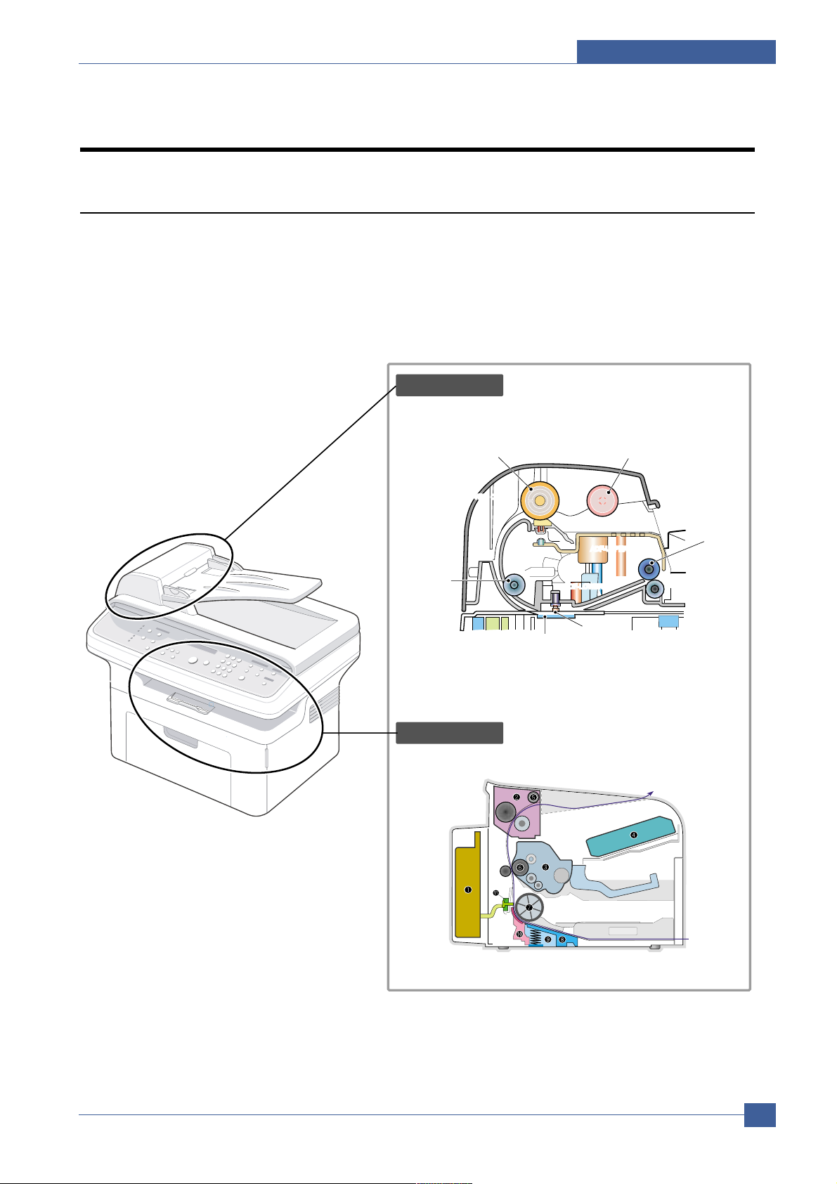
3.1 System Layout
The SCX-4521F/4321 is roughly made up Main Control part, Operation Panel part, Scanner part, Line
Interface part and Power part. Each Part is separated Module which focus on common and standard design
of different kind products. main control part adopting Fax & LBP Printer exclusive Controller is chorus2
CPU(ASIC) and 1 Board. Scanner part is composed of ADF and Platen and is connected with Main by
Harness.
ADF ROLLER
Scanner part
Engine Part
ADF-UPPER
PICK-UP ROLLER
EXIT ROLER
WHITE BAR
ADF-GLASS
FEED ROLLER
SCAN UPPERSCAN UPPERSCAN UPPER
ADF-LOWER
COVER OPEN
BIN PATH
Page 19

Samsung Electronics
Service Manual
System Overview
3-2
3.1.1 Feeding section
There is a universal cassette which automatically loads paper and the manual feed which supplies paper
single sheet at a time. The cassette has a friction pad which separates paper to ensure single sheet
feeding, and it has a sensor, which checks when the paper tray is empty.
- Feeding Method: MP Cassette Type
- Feeding Standard: Center Loading
- Feeding Capacity: Cassette-150 sheets (75g/m2, 20lb paper standard)
Manual 1 sheet (Paper, OHP, Envelop, etc.)
- Paper detecting sensor: Photo sensor
- Paper size sensor: None
3.1.2 Transfer Ass’y
This consists of the PTL (pre-transfer lamp) and the Transfer Roller. The PTL shines a light onto the OPC
drum. This lowers the charge on the drum’s surface and improves transfer efficiency.
The transfer roller transfers toner from the OPC drum surface to the paper.
- Life expectancy: Over 50,000 sheets (at 16~30°C)
3.1.3 Driver Ass’y
- Gear driven power unit. The motor supplies power to the paper feed unit, the fuser unit, and the toner
cartridge.
3.1.4 Fixing Part(Fuser)
- The fuser consists of the Heat Lamp, Heat Roller, Pressure Roller, Thermistor, and Thermostat. It fixes
toner to the paper using pressure and heat to complete the printing job.
3.1.4.1 Temperature-Intercepting Device (Thermostat)
The thermostat is a temperature sensing device, which cuts off the power to the heat lamp to prevent
overheating fire when the heat lamp or heat roller overheats.
3.1.4.2 Temperature Detecting Sensor (Thermistor)
The Thermistor detects the surface temperature of the heat roller, this information is sent to the main
processor which uses this information to regulate the temperature of the heat roller.
3.1.4.3 Heat Roller
The surface of the Heat Roller is heated by the Heat Lamp. As the paper passes between the Heat and
Pressure rollers the toner is melted and fixed permanently to the paper. The surface of the roller is coated
with Teflon. This ensures that toner does not adhere to the roller surface.
Page 20

System Overview
Samsung Electronics
Service Manual
3-3
3.1.4.4 Pressure roller
The Pressure Roller mounted under the heat roller, it is made of a silicon resin, and the surface of the roller
is coated with Teflon. This ensures that toner does not adhere to the roller surface.
3.1.4.5 Safety Features
• To prevent overheating
- 1st protection device: Hardware cuts off when overheated
- 2nd protection device: Software cuts off when overheated
- 3rd protection device: Thermostat cuts off mains power to the lamp.
• Safety device
- Fuser power is cut off when the front cover is opened
- LSU power is cut off when the front cover is opened
- The temperature of the fuser cover's surface is maintained at less than 80°C to protect the user and a
caution label is attached where the customer can see it easily when the rear cover is opened.
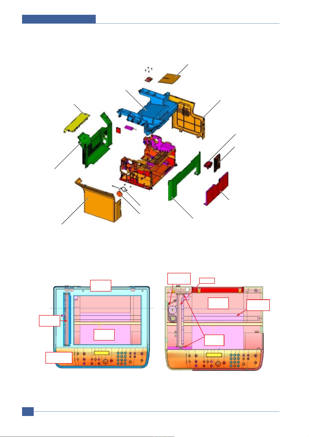
Page 21
Samsung Electronics
Service Manual
System Overview
3-4
STACKER
COVER-M-SIDE R
EXTEND-SMALL
EXTEND-LARGE
TRAY CASSETTE
COVER-M_DEVE
FIXING BKT
SPEKER
COVER-M-SIDE-L
COVER-M_REAR
COVER-M_JAM
COVER-M_MIDDLE
SCAN
UPPER
MOTOR
ASS’Y
SCAN
LOWER
TIMING
BELT
CIS
SLIDER
-CIS
ADF
GLASS
SCAN
GLASS
KEY & OPE
COVER
[Case part figure]
[Scan part figure]
Page 22

System Overview
Samsung Electronics
Service Manual
3-5
3.2 Engine H/W Specification
1) Recording Method : LSU(Laser Scanning Unit)
2) Printing Speed : 20ppm
(In continuing printing base Letter, printing pages from 2nd to last during 1min)
3) Recording Density : 600 dpi
4) Cassette Capa. : Cassette ; 150sheets(75g/ Base), 1-sheet Feeding : N/A((DRIVE Selection : Paper, OHP,
Envelop - 1 sheet)
5) Manual Tray : All paper 1 sheet
6) Paper Size : Cassette ,Manual ; Width = 76 ~ 216mm, Length = 125mm ~ 356mm
7) Effective recording size
- A4 :202 x 291 mm
- Letter :208 x273mm
- Legal : 208 x 350 mm
- Folio : 208 x 325 mm
- TopMargin: 2 2 mm
- Left, Right Margin : 2
2 mm
8) CRU(Toner Cartridge)Life : 3,000pages Printing(A4, ISO 19752 Standard Pattern Printing)
9) First Print Out Time : within 11sec ( Standby )
10) Warming up time : within 35sec (Ambient : 25 °C)
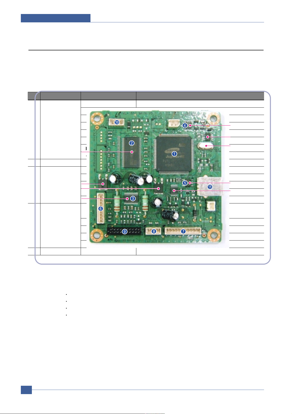
3.2.1 Main Board Control Part
Main control part of SCX-4521F is made of ASIC(CPU, Image processor, PC I/F part include, Scan interface part,
FAX Modem part and Printing process I/F part. CPU handles the BUS control, I/O interface, scan interface, PC
interface and other miscellaneous driver circuit.
1) Main Board
- Main Board has a function of sending Current Image Video Data to LSU of the machine, controlling motor
Driving Circuit and monitoring Paper Exit Sensor, Cover Open switch, OPE Panel Inputs.
2) Main Controller
- CPU : Chorus2 is the main CPU and is made up on the 16/32bit RISC architecture using ARM7TDMI
core. Main CPU controls the whole system according to the program code which stored in the
Flash-ROM memory.
- Summary of the Key Function Block:
1.8V for internal Core, 3.3V for I/O Pad with 4KByte Cache.
Image Processor included.
On-Chip clock generator with PLL.
Memory and External Bank Control.
DMA Control (5-Channel)
Interrupt Control.
2-port USB Host/1-port USB device(ver 1.1) interface control.
Parallel interface control.
UART(2-Channel)
Page 23

Samsung Electronics
Service Manual
System Overview
3-6
Synchronous Serial Interface Control.
A/D Converter(10-bit, 2channel).
General I/O Port control.
Tone Generator.
RTC with calendar function.
S/W Assistant function(Rotator)
- Flash Memory : Stores system program and can be updated to the newer system program code through
the PC interface. It stores the FAX Journal List, One Touch dial number, speed dial number, and machine
configuration setup data.
Capcity : 2 Mbyte
Access Time : 70 nsec
- SDRAM : SDRAM is used for Print Buffer, Scan buffer when scanning, ECM Buffer when FAX Receiving,
and system working memory.
Capacity : 16 Mbyte
Access Time : 66MHz based on system bus clock.
Data Backup : 72 Hours
Backup Battery Charging Time : 100hours when completely discharged.
3.2.2 Scan Part
1) Image Signal Input Part
- Image Signal from CIS has a level of about 1.2V and is goes to ADC of Chorus2.
After ADC, CIS analog signal will be converted to 8-bit Digital signal.
2) Image Processing
- On the surface of the original paper, the light from the CIS LED reflected and goes to the CIS Sensor.
Then the light is converted to the appropriate voltage suitable for ADC input. Analog signal from CIS
sensor is used for ADC input then is converted to 8-bit digital data. Image processor of the Chorus2 will
do the Shading correction function at first, then Gamma correction function next. After then, the data goes
to different module according to the copy or FAX resolution mode. When Text mode, the image data
goes to LAT module, when Photo mode, the image data goes to Error Diffusion module, when PC-Scan
mode, the image data goes directly to the PC through DMA access.
Summary of the Image sensor interface is as below;
- Minimum Scan Line Time :1.5ms
- Scan Resolution : 600*600 dpi
- Scan Width : 208mm
- Function
White Shading Correction
Gamma Correction
CIS Interface
256 Gray Scale
Page 24

System Overview
Samsung Electronics
Service Manual
3-7
3) CIS Driving Part
- CIS Supply Voltage : +3.3V
- CIS Max frequency : 5MHz
- CISLinetime
Fax/Copy - 1.5ms
PC-Scan - 4.5ms
- White output volt. : Max 0.8V
4) ADF Driving Part : Driving ADF Stepper motor, and the maximum motor speed is 2000PPS.
- MOTOR DRIVER : A3978(Allegro)
- Driving Voltage : 24V DC
- Phase : 2-2 Phase 2000PPS at Quick Scan,
2-2 Phase 1000PPS AT Fine Scan,
2-2 Phase 667PPS AT Super Fine Scan
3.2.3 Fax Modem Part
1) Modem Part
The modem part is consist of FM336(FAX Modem chip), LIU(Line Interface Unit) and modem analog front
end(AFE) functional part.
- The feature of the FM336 modem chip is as below;
Communication Mode : Half Duplex
Modem Method
GROUP 3 : ITU-T V34, V17, V29, V27ter
Tonal Signal : ITU-T T.30
Binary Signal : ITU-T V.21, T.30
Image Transmission Time : 3sec ( ITU-T NO.1 CHART/Memory Tx/ECM )
Data Compress : MH, MR, MMR, JPEG
Modem Speed : 33600 / 28800 / 14400 / 12000 / 9600 / 7200 / 4800 / 2400 bps
Receive Level : 0 ~ -48dBm
Output Level
Adjustable : -6 ~ -15dBm ( 1dBm Step )
Initial Setting : -12dBm
Receive dynamic range:
0 dBmto-43 dBmfor V.17,V.29,V.27 ter and V.21
-9 dBm to -43 dBm for V.34 halfduplex
2) The Gain of the Line signal can be adjusted by setting the register value of the FAX modem chip ,Tx and Rx path
is almost directly connected to the impedance matching transformer of the LIU.
- Adjust Tx Level within Setting Level+0,-2dB range.
- Adjust Rx Level that has the same level as the TIMS out level if possible, and must not exceed the TIMS
out level.
3) Speaker Driving Part
Analog Switch(MC14053BD) makes a path for FAX Tone, Ring, Key click sound and Analog MUX
(MC14051) makes a different signal level so that the the Speaker driver chip(MC34119) can driving the
Speaker with different sound volume.
Page 25
Samsung Electronics
Service Manual
System Overview
3-8
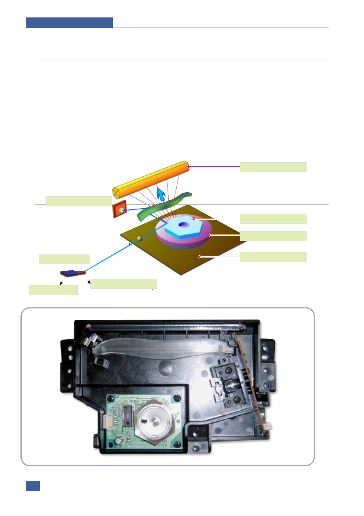
3.2.4 Printing Process Part
Printing Process part is made of PC-Interface part, PVC(Priter Video Controller), LSU control part, High Voltage
control part and Fuser Unit control part. PC-interface core is included in the Chorus2 ASIC and controls the PCinterface. LSU control part controls the LSU polygon motor, Laser diode, video data output so thatthe printing image
can be made up on the OPC Drum.
3.2.5 Line Interface Part
Line interface part helps the machine connect to the PSTN or PABX Line and is made of almost primary circuit.
Its main function is Line connection, Line state monitoring and TAD interface that enables a extension telephone or
TAD machine to connect to the SCX-4521F machine.
3.2.6 Engine Paper Feeding
1) Feeding Type : MP Cassette Type
2) Feeding Standard : Center Loading
3) Feeding Qty : Cassette 150 sheets (75g/ , 20lb paper standard)
4) 1 sheet (Paper, OHP, Envelope etc.)
5) Separating Type: Cassette - Friction Pad Type
6) Manual Tray : 1 sheet
7) Driver Type : Driving by Gearing from Main Motor
8) Pick_up Roller Driver : Solenoid
9) Pick up Roller Rubber Material : EPDM+IR =1.3 or more
10) Pick up Velocity : 94.8731mm/Sec (Process : 93.0667mm/sec)
11) Paper detecting Sensor : Photo Sensor
12) Paper Size Sensor : None
13) Paper Separating Pad Material : NBB 52 °, =0.8~1.2
14) Separating Pad Pressure : TBD 150 gf
15) Pick_up Roller RPM : 47.683 RPM
16) Feeding Pressure (Same as Transfer Roller)
17) Paper Exit Type : Face Down
18) Feed Roller Force : TBD Kg.f or more.
19) Spring Feed Tensile Force : TBD gf
20) Feed roller Velocity : mm/sec
21) Feed Roller Material
22) Exit Sensor : Photo Sensor
OPC Drum
Photo Diode
LD Driver circit
Protector panel
LD(Laser Diode)
Polygon Mirror
Polygon Motor
Motor Driver
Page 26

System Overview
Samsung Electronics
Service Manual
3-9
3.3 Deverope Process
- Developing Method : Non magnetic 1 element contacting method
- Toner : Non magnetic 1 element shatter type toner
- Toner Qty:35gf /60gf (1k/3k)
- The life span of toner 1k/3k sheets (ISO 19752 Standard Coverage )
- Toner Residual Sensor : None
- OPC Cleaning : Use the conventional cleaning blade
- Handling of wasted toner : Discard by collecting waste-toner at waste-toner bin.
- OPC Drum Protecting Shutter : None
- Classifying device for toner cartridge: ID is classified by interruption of the frame channel.
- Development Roller type : conductive elastic roller
- Doctor BLADE Type : Regulating toner layer by pressure
- Charge Roller Type : Conductive Roller Contact-Charge
3.3.1 Fuser Specification
1) Heat Lamp
- Heat Lamp Terminal Shape : Terminal Single Type
- Voltage 120 V : 115 5 %, 220 V : 230 5 %
- Capacity : 600 Watt 30 W
- Light Qty Distribution : 140%
- Life : 3000 Hr
2) Thermostat
- Thermostat Type : Non-Contact type THERMOSTAT
- Control Temperature : 150°C 5°C
3) Thermistor
- Thermistor Type : HF-R0060 (SEMITEC 364FL Type)
- Temperature Resistance : 7 k (180 °C)
- SYSTEM Temperature SETTING
Stand by : 165 5°C
Printing : 175 5°C(5 minutes before)
170°C
5°C(5 minutes after)
Overshoot: 200°C or less
Overheat :210°C or less
4) Safety Relevant Facts
- Protecting device when overheating
1st protecting device : H/W cuts off when detecting an overheating
2st protecting device : S/W cuts off when detecting overheating
3st protecting device : Thermostat cuts off the power
- Safety device
The power of Fuser is cut-off after front cover is open.
The overheating safety device for customer
The surface temperature of the Fuser Cover is under 80°C
Page 27

Samsung Electronics
Service Manual
System Overview
3-10
3.4 Sanner Part
600dpi Color CIS Module for Flat bed, SCX-4521F uses the CIS scanning method
1) CIS SPEC
- Scanning size : 216 mm ( width for letter-size)
- Light source : LED
- Scanning sensor: CIS 600/300 dpi
- Scanning mode : Color SCAN / Mono SCAN
- MTF : 30% (300 dpi Chart)
- CIS interface : Analog output
- Power supply : 3.3V
- Clock Frequency: 5MHz max.
- Number of output : 1
- LED Current : Red/Green/Blue : 60mA
- Clamp Level : 1.1V
- Connection : 12 pin FFC connector (pitch 1.0mm)
2) Scan Resolution
(a) Transmission
- Normal : Vertial: 3.85 Line/mm, Horizontal: 8 Pels/mm :203 x 98dpi
- Fine : Vertial: 7.7 Line/mm, Horizontal: 8 Pels/mm :203 x 196dpi
- Super Fine : Vertial: 11.8 Line/mm, Horizontal: 11.8 Pels/mm ;300 x 300dpi
(b) When Copy : Vertial: 11.8 Line/mm, Horizontal: 23.6 Pels/mm :600x300dpi(ADF)
Vertial: 23.6 Line/mm, Horizontal: 23.6 Pels/mm :600x600dpi(Platen)
3) Half Tone (Gray Scale) : 256 Levels
4) Scan Line Time
(a) Tx
- Normal : 1.5 ms/Line
- Fine : 1.5 ms/Line
- Super Fine : 1.5 ms/Line
(b) Copy : 1.5 ms/Line
(c) Scan
- Color : 4.5msec/line
- Gray : 4.5msec/line
- Mono : 4.5msec/line
5) Scanning Width
- MAX SCAN WIDTH : 216 mm (8.5 inches)
- Effective Scan Width: 208mm
6) ADF Motor
(a) Motor Spec
- : 24VDC
- : 0.6A(Peak)
Page 28

System Overview
Samsung Electronics
Service Manual
3-11
7) Motor Driver speed & method
(a) FAX Transmission
- Normal Mode : 2000 pps
- Fine Mode : 1000 pps
- Super Fine Mode : 667 pps
(b) Copy Job : 667 pps, 2-2
- max(30sheets) : 50gf
- min(1sheets) : 20gf
8) Document Detect sensor
(a) Type : Photo interrupt
(b) Position : ADF PBA
(c) LED - max current : 50mA
- max voltage : 3.3V
(d) Output - Logic "H" : No Paper
- Logic "L" : Paper
(e) Lever-Sensor DOC : ADF Lower Torsion Spring
9) Regi Detect sensor
(a) Type : Photo interrupt
(b) Position : ADF PBA
(c) LED - max current : 50mA
- max voltage : 3.3V
(d) Output - Logic "H" : No Paper
- Logic "L" : Paper
(e) Lever-Sensor DOC : ADF Lower Torsion Spring
10) Document Scan sensor
(a) Type : Photo interrupt
(b) Position : ADF PBA
(c) LED : - Max current : 50mA
- Max Voltage : 3.3V
(d) Output - Logic "H" : Off(No Position), No Paper
- Logic "L" : On (Doc Position), Paper
(e) LEVER - SENSOR SCAN : Scan Lower Torsion Spring
Page 29
Samsung Electronics
Service Manual
System Overview
3-12
3.5 OPE(Operational Panel Equipment)
1) Ope Panel
OPE Panel has a MICOM Chip on it and communicates with Main CPU using Serial communication
Line(SIO). OPE Panel consists of Micom, Key Matrix Part, LED Driving Part and LCD Part.
2) Key Description
3) LCD Part
- Number of Characters : 16 Characters x 2 line
Clock, Date display
System Status display
Alarm, Error Message display
Function Dialog Message display
No Part Feature Function
1 Common 3*4Key Dialing and Option Input
Start Starting Fax/Copy Job
Stop/Clear Cancel Current Job/Return to default
Menu Option select
Upper Level Return to upper level menu
Enter Option select/Execute
Next menu or Next option item
Previous menu or Previous option item
2 Save Toner Save TONER SAVE MODE select
3 Copy Reduce/Enlarge Select ZOOM ratio when copy
No.of Copies Select the number of copies
Original Type Change Copy Modes(Text,Text/Photo,Photo)
Darkness
Change the Darkness of the Copied image (Light/Normal/Dark)
Favorite Copy Select one of the predefined Copy templates.
4 Fax Resolution STANDARD>FINE>SUPER
FINE>PHOTO>COLOR
Phone Book Search the user defined Phone number.
Broadcasting When sending FAX data to many place in the same time.
On Hook Dial On Hook Dial
Redial / Pause Last number Redial / Pause
5 Scan Scan to select [scan to PC], [scan to FAX], [scan to E-mail] function.
U1
U3
12.0MHz
U8
U9
U12
U10
U7
U5
(IC-DRAM/
512K x 16Bit)
(IC-POSI, ADSUST REG)
(IC-CMOS LOGIC, INVER TER)
(IC-MOTOR DRIVER)
(IC-VOLTAGE COMP)
(IC-CLOCK GENERATOR)
(IC-EEPROM/256x12Bit)
(IC-POSI, FLXED REG)
Page 30

System Overview
Samsung Electronics
Service Manual
3-13
3.6 SMPS & HVPS
It is the power source of entire system. It is assembled by an independent module, so it is possible to use for
common use. It is mounted at back of the machine. Power part is divided by two independent PBAs - SMPS PBA
and HVPS PBA. SMPS PBA supplies the DC power for driving the system and supplies the AC power to the fuser.
SMPS has two output channels : +5V and +24V. HVPS PBA supplies High voltage to the developer part to make a
printing image on the paper. High voltages applied to the MHV, THV, DEV, SUPPLY.
3.6.1 SMPS
1) AC Input
- Input Rated Voltage : AC 220V ~ 240V / AC 110V ~ 127V
- Input Voltage fluctuating range: AC 180V ~ 270V / AC 100V ~ 135V
- Rated Frequency : 50/60 Hz
- Frequency fluctuating range : 47 ~ 63 Hz
- Input Current : Under 4.0Arms / 2.5Arms
(But, the status when lamp is off or rated voltage is inputted/outputted )
2) Rated Output Power
3) Consumption Power
NO Items CH1 CH2 Remarks
1 CHANNEL +5V +24.0V
2 CONNECTOR PIN CON 2 CON 2 Jam cover switch
5V PIN : #5pin 24V PIN: #2, #3, #4 included
GND PIN: #6pin GND PIN: #7pin
3 Rated Output +5V ± 5%(4.75 ~ 5.25V)
+24V -10%/+15%(21.6V ~ 27.6V)
4 Max. Output current 0.8 A 2.5 A
5 Peak Loading current 1.0 A 2.7 A
within 1ms Duration
6 RIPPLE NOISE Voltage 100mVp-p or less 500mVp-p or less
7 Maximum output 2.5W 36W
8 Peak output 4W 55.2W 1ms
9 Protection for loading Fuse Protection or Shutdown Fuse Protection or Shutdown
shortage and within 1.5A ~ 3.0A range. within 3.5A ~ 4.5A range.
overflowing current
NO Item CH1(+5V) CH2(24V) System
1 Stand-By 0.6 A 1.3 A AVG : 65Wh
2 Printing 0.8 A 1.9 A AVG : 350Wh
3 Sleep-Mode 0.5 A 0.3 A AVG : 10Wh
Page 31

Samsung Electronics
Service Manual
System Overview
3-14
4) Power Cord Length : 1830 50mm
5) Power Cord Switch : Exist
6) Feature
- Withstand Resistance : 100 or more (at DC 500V)
- Insulating revisiting pressure : Must be no problem within 1 min. (at1000Vac,10mA)
- Leaking Current : under 3.5mA
- Running Current : under 40A PEAK (AT 25 °C,COLDSTART)
under 50A PEAK (In other conditions)
- Rising Time : within 2Sec
- FallingTime : over 20ms
- Surge : Ring Wave 6KV-500A (Normal, Common)
7) Environment Condition
- Operating temperature range : 0 °C ~ 40 °C
- Maintaining temperature range : -20 °C ~ 40 °C
- Preserving Humidity Condition : 10% ~ 90% RH
- Operating atmospheric pressure range : 1atm
8) EMI Requirement : CISPR, FCC, CE, MIC,
9) Safety Requirement : IEC950 UL1950, CSA950, C-UL, Semko, EK, CB, CCC(CCIB),GOST, EPA,
3.6.2 HVPS Board
The HVPS board creates the high voltage of THV/MHV/Supply/Dev and supplies them to the developer part for
making best quality printing image. The HVPS part takes the 24V and outputs the high voltage such as
THV/MHV/Supply/Dev, and the outputted high voltage is supplied to the toner, OPC cartridge, and transfer roller.
(a) Transfer High Voltage (THV+)
- Input Voltage : 24 V DC +15% / -10% (21.6V~27.6V)
- Out Voltage : +1300KV 1.5% (200 Load )
- Out Voltage Trigger : 6.5
- Input Voltage Variation : 5 %
Load Variation :
5 %
- Out Voltage Rising Time : 100 ms Max
- Out VoltageFalling Time : 100 ms Max
- Transfer Variation Voltage on Environment Variation : +500 V ~ +5000V
- Control Method on environment : THV-PWM ACTIVE, transfer Active signal, of environment sensing
voltage is input and get feed back current, and recalculate it to resistance .
- Control method on transfer output voltage : It is controlled by changing its duty of THVPWM Signal as
follows. 10% Duty : +500V, 90% Duty : +5000V
(b) Charge Voltage (MHV)
- Input Voltage : 24 V DC +15% / -10% (21.6V~27.6V)
- Out Voltage : -1300KV 50V(50 Load)
- Out Voltage Rising Time : 50 ms Max
- Out VoltageFalling Time : 50msMax
- Out Voltage Range : 30 ~ 1000
- Output Control Signal(MHV-PWM) : Active Low PWM signal for controlling MHV
Page 32

System Overview
Samsung Electronics
Service Manual
3-15
(c)Developing Voltage (DEV)
- Input Voltage : 24V DC +15% / -10% (21.6V~27.6V)
- Output Voltage: -350V 20V (50 Load)
- Output Voltage Fluctuation range: PWM Control
- Input contrast of the output stability degree : 5 %orless
- Loading contrast : 5 %orless
- Output Voltage Rising Time : 50 ms Max
- Output Voltage Falling Time : 50 ms Max
- Output Loading range : 10 ~1000
- Output Control Signal (BIAS-PWM) : Active Low PWM signal for controlling MHV
(d) Supply
- Output Voltage : -550V 50V(50 Load)
- Input contrast of the output stability degree : under 5 %
- Loading contrast : 5 %orless
- Output Voltage Rising Time : 50 ms Max
- Output Voltage Falling Time : 50 ms Max
- Output Loading range : 10 ~ 1000
- Output Control Signal (BIAS-PWM) : Active Low PWM signal for controlling MHV
3.7 FUSER AC POWER CONTROL
The Fuser(HEAT LAMP) gets heat from AC power. The AC power controls the switch with the Triac, a
semiconductor switch. The 'ON/OFF control' is operated when the gate of the Triac is turned on/off by Phototriac
(insulting part). In other words, the AC control part is passive circuit, so it turns the heater on/off with
taking signal from engine control part.
When the 'HEATERON' signal is turned on at engine,the LED of PC102 (Photo Triac) takes the voltage and
flashes. From the flashing light, the Triac part (light receiving part) takes the voltage,and the voltage is supplied to
the gate of Triac and flows into the Triac. As a result, the AC current flows in the heat lamp, and heat is occurred.
On the other hand, when the signal is off, the PC102 is off, the voltage is cut off at the gate of Triac, the Triac
becomes off, and then the heat lamp is turned off.
1) Triac feature : 12A, 600V SWITCHING
2) Phototriac Coupler (PC102)
- Turn OnIf Current : 15mA~50mA(Design : 16mA)
- High Repetive Peak Off State Voltage : Min 600V
Page 33

Samsung Electronics
Service Manual
Alignment and Adjustments
4-1
4
4
4. Alignment and Adjustments
4.1 User Mode
The table below shows the map of User settings available in User Mode. These are fully described in the
User Guide and are not included here.
Paper Type
Plain Paper, Thick, Thin, Plain Paper
Bond, Color Paper, Card
stock, Labels, Transparency,
Envelope, Preprinted
Paper Size A4, Legal, Executive, Folio By Country
A5, B5, A6, Letter
Machine ID Fax:
(Only SCX-4521F) ID:
Date & Time 00-00-0000
(only SCX-4521F) 00:00(AM)
Clock Mode 12, 24 hours 12hours
(only SCX-4521F)
Language [English/FRANCAIS/Espanol/ English
Portugues/Deutsch/Italiano/
Pycckn/Norsk/Polski/
Suomi/Magyar/Dansk/
cestina/Svenska/Turkse
- 15 language
Power Save On 5, 10, 15, 30, 45 min. 5
Off
Ignore Toner On
Off
USB Mode Fast/Slow Fast
1. Paper Setting
Paper Type
2.Machine Setup
Machine ID
1
2
1
2
3
4
5
6
7
1st level 2nd level 3rd level Default Value
RETURN -- RETURN
left/right && Enter -- 14 character left/right && Enter
Page 34

Alignment and Adjustments
Samsung Electronics
Service Manual
4-2
Default-Change Darkness Light/Normal/Dark Normal
Original Type Text, Text/Photo, Photo Text
Reduce/Enlarge [Original(100%)] 100%
[LGL
LTR(78%)]
[LGL
A4(83%)]
[A4
A5](71%)]
[A4
LTR(94%)]
[EXE
LTR(104%)]
[A5
A4](141%)]
25%
50%
150%
200%
400%
[Custom:25-400]
No. of Copies [1-99] 1
Timeout 15,30,60,180Sec, Off 60sec
Favorite copy Clone
Copy Collate
Autofit
2 side in 1 Pg
2 UP
4 UP
Poster
Off
Clone
Copy Collate
Autofit
ID Card Copy
2 UP This will set to 2UP
4 UP This will set to 4UP
Poster
3.Copy Setup
Default-Change
4. Copy Feature
Off
1
2
3
1
2
3
4
5
6
7
8
1st level 2nd level 3rd level Default Value
RETURN -- RETURN
left/right && Enter -- 14 character left/right && Enter
Page 35

Samsung Electronics
Service Manual
Alignment and Adjustments
4-3
Default-Change Resolution Standard/Fine/Super Standard
Fine/Photo/Color
Ring to Answer 1~7 2
Darkness Light/Normal/Dark Normal
Redial Term 1~15Min 3minutes
Redials 1~13times 7times
MSG Confirm On, Off, On-Error On-Error
Image TCR On, Off
Auto Report On, Off On
Auto Reduction On, Off On
Discard Size 0~30mm 20mm
Receive Code 0~9 9
DRPD Mode set
Receive Mode Fax, Tel, Ans/Fax, DRPD
Delay Fax Fax:
Priority Fax Fax:
Add Page Yes, No
Cancel Job Yes, No
Send Forward On,Off Off
RCV Forward On Start Time/ End Time
Print Local Copy
Off Off
Junk Fax Setup On Fax:
Off Off
Secure Receive On,Off, Print Off
Prefix Dial FAX: xxxxx (5 digits)
Stamp RCV Name On, Off Off
ECM Mode On, Off On
Phone Book
(only SCX-4521F)
Sent Report
(only SCX-4521F)
RCV Report
(only SCX-4521F)
System Data
Scheduled Jobs
(only SCX-4521F)
MSG Confirm
(only SCX-4521F)
Junk Fax List
(only SCX-4521F) 10 ea
Speaker On, Off, Comm. Comm.
Ringer Off, Low,Med,High Med
Key Sound On, Off Off
Alarm Sound On, Off On
5. Fax Setup
(only SCX-4521F)
Default-Change
6. Fax Feature
(only SCX-4521F)
Delay Fax
7. Advanced fax
(only SCX-4521F)
8. Reports
Phone Book
9. Sound/Volume
Speaker
1
2
3
4
5
6
7
8
9
10
11
12
13
1
2
3
4
1
2
3
4
5
6
7
1
2
3
4
5
6
7
1
2
3
4
1st level 2nd level 3rd level Default Value
RETURN -- RETURN
left/right && Enter -- 14 character left/right && Enter
<continue..>
Page 36

Alignment and Adjustments
Samsung Electronics
Service Manual
4-4
Clean Drum On,Off Off
Notify Toner On,Off Off
Clear Memory Clear All Mem.
Paper setting
Machine Setup
Copy Setup
Fax Setup
Fax Feature
Advanced Fax
Sound/Volume
Sent Report
RCV Report
Phone Book
Remote Test On Off
(only SCX-4521F) Off
10. Maintenance
Clean Drum
1
2
3
4
1st level 2nd level 3rd level Default Value
RETURN -- RETURN
left/right && Enter -- 14 character left/right && Enter
<continue..>
Page 37

Samsung Electronics
Service Manual
Alignment and Adjustments
4-5
4.2 Tech Mode and Setting
4.2.1 How to Enter Tech Mode
In service (tech) mode the technician can check the machine and perform various tests to help with failure
diagnosis.
When in Tech mode the machine still performs all normal operations.
To enter the Tech mode (SCX-4521F)
To enter the Tech mode press in sequence and the LCD
briefly displays ‘TECH’, the machine has entered service (tech) mode.
To enter the Tech mode (SCX-4321)
To enter the Tech mode press in sequence and the LCD
briefly displays ‘TECH’, the machine has entered service (tech) mode.
Page 38

Alignment and Adjustments
Samsung Electronics
Service Manual
4-6
4.2.2 Setting-up System in Tech Mode
Data Setup Send Level -9~-15 -12
(only SCX-4521F)
Modem Speed 33.6, 28.8, 14.4, 12.0, 9.6, 4.8 33.6
(only SCX-4521F)
Error Rate (only SCX-4521F) 5%, 10% 10%
Dial Mode (only SCX-4521F) Tone, Pulse Tone
Notify Toner Customer No.
Customer Name
Service No.
Serial No.
Clear All Mem.
Clear Count Total Page Count Enter Password
CRU Print CNT
FLT Scan Count
ADF Scan Count
Used Toner CNT
Edit Toner Dot
Flash Upgrade Local
Remote
Silence Time Off/ 12 Sec/Unlimited Off
(only SCX-4521F)
Machine Test Switch Test
Modem Test
(only SCX-4521F)
Dram Test
Rom Test
Pattern Test
Shading Test
Report Protocol(only SCX-4521F)
System Data
Key History Error Info
New Cartridge
Tech Mode
Data Setup
1
2
3
1st level 2nd level 3rd level Default Value
RETURN -- RETURN
left/right && Enter -- 14 character left/right && Enter
Page 39

Samsung Electronics
Service Manual
Alignment and Adjustments
4-7
4.2.3 Setting
4.2.3.1 Changing the Display Language
To change the language that displays on the control panel, follow these steps:
1. Press Menu until “Machine Setup” appears on the top line of the display.
2. Press the scroll button ( or ) until “Language” appears on the bottom line of the display.
3. Press Enter. The current setting appears on the bottom line of the display.
4. Press the scroll button ( or ) until the language you want appears on the display.
5. Press Enter to save the selection.
6. To return to Standby mode, press Stop/Clear.
4.2.3.2 Setting the Machine ID (Only for SCX-4521F)
In some countries, you are required by law to indicate your fax number on any fax you send. The Machine
ID, containing your telephone number and name (or company name), will be printed at the top of each page
sent from your machine.
1. Press Menu until “Machine Setup” appears on the top line of the display. The first available menu item,
“Machine ID,” displays on the bottom line.
2. Press Enter. The display asks you to enter the fax number.
If there is a number already set, the number appears.
3. Enter your fax number using the number keypad.
4. Press Enter when the number on the display is correct. The display asks you to enter an ID.
5. Enter your name or the company name using the number keypad.
You can enter alphanumeric characters using the number keypad, and include special symbols by
pressing the 0 button.
For details on how to use the number keypad to enter alphanumeric characters.
If you want to enter the same letter or number in succession, enter one digit, move the cursor by
pressing the button and enter the next digit.
If you want to insert a space in the name, you can also use the button to move the cursor to skip the
position.
6. Press Enter when the name on the display is correct.
7. To return to Standby mode, press Stop/Clear.
NOTE: If you make a mistake while entering numbers, press the button to delete the last digit.
Page 40

Alignment and Adjustments
Samsung Electronics
Service Manual
4-8
4.2.3.3 Setting the Date and Time
When you turn your machine on for the first time, the display prompts you to enter the current date and time.
After entering, it will not appear anymore. For the SCX-4521F, all of your faxes will have the date and time
printed on them.
1. Press Menu until “Machine Setup” appears on the top line of the display.
2. Press the scroll button ( or ) to display “Date & Time” on the bottom line and press Enter.
3. Enter the correct time and date using the number keypad.
For the SCX-4321, press the scroll button ( or ) to enter the time and date.
Month = 01 ~ 12
Day = 01 ~ 31
Year = requires four digits
Hour = 01 ~ 12 (12-hour mode)
00 ~ 23 (24-hour mode)
Minute = 00 ~ 59
You can also use the scroll button ( or ) to move the cursor under the digit you want to correct
and enter a new number. For the SCX-4321, you can use Enter or Upper Level to move the cursor.
4. To sel ect “ AM” or “PM” for 12-hour format, press the or # button or any number button.
For the SCX-4321, press Enter and then the scroll button ( or ).
When the cursor is not under the AM or PM indicator, pressing the or # button immediately moves
the cursor to the indicator. For the SCX-4321, press the scroll button ( or ) to move the cursor to
the indicator.
You can change the clock mode to 24-hour format (e.g. 01:00 PM as 13:00).
5. Press Enter when the time and date on the display is correct.
When you enter a wrong number, the machine beeps and does not proceed to the next step. If this
happens, just reenter the correct number.
6. To return to Standby mode, press Stop/Clear.
4.2.3.4 Changing the Clock Mode
You can set your machine to display the current time using either a 12-hour or 24-hour format.
1. Press Menu until “Machine Setup” appears on the top line of the display.
2. Press the scroll button ( or ) until you see “Clock Mode” on the bottom line and press Enter.
The clock mode currently set for the machine displays.
3. Press the scroll button ( or ) to select the other mode and then press Enter to save the selection.
4. To return to Standby mode, press Stop/Clear.
NOTE: If power to the machine is cut off, you need to reset the correct time and date once the power has been
restored.
NOTE: The date format may differ from country to country.
Page 41

Samsung Electronics
Service Manual
Alignment and Adjustments
4-9
4.2.3.5 Setting the Paper Size and Type
After loading paper in the tray, you need to set the paper size and type using the control panel buttons.
These settings will apply to copy and fax modes. For PC-printing, you need to select the paper size and type
in the application program you use on your PC.
1. Press Menu.
The display shows “Paper Setting” on the top line of the display.
2. Press the scroll button ( or ) to display “Paper Size” on the bottom line and press Enter to access
the menu item.
3. Use the scroll button ( or ) to find the paper size you are using and press Enter to save it.
4. Press the button to scroll to “Paper Type” and press Enter to access the menu item.
5. Use the scroll button ( or ) to find the paper type you are using and press Enter to save it.
6. To return to Standby mode, press Stop/Clear.
4.2.3.6 Setting Sounds (Only for SCX-4521F)
You can control the following sounds:
• Speaker: You can turn on or off the sounds from the telephone line through the speaker, such as the dial
tone or a fax tone. With this option set to “Comm.” the speaker is on until the remote machine
answers.
• Ringer: You can adjust the ringer volume.
• Key Sound: With this option set to “On” a key tone sounds each time a key is pressed.
• Alarm Sound: You can turn the alarm sound on or off. With this option set to “On” an alarm tone sounds
when an error occurs or fax communication ends.
• You can adjust the volume level using the On Hook Dial button.
4.2.3.7 Speaker, Ringer, Key Sound, and Alarm Sound
1. Press Menu until “Sound/Volume” appears on the top line of the display.
2. Press the scroll button ( or ) to scroll through the options. Press Enter when you see the desired
sound option.
3. Press the scroll button ( or ) to display the desired status or volume for the option you have
selected. You will see the selection on the bottom line of the display. For the ringer volume, you can
select “Off,” “Low,” “Med,” and “High”. Setting “Off” means that the ringer does not sound. The machine
works normally even if the ringer is turned off.
4. Press Enter to save the selection. The next sound option appears.
5. If necessary, repeat steps 2 through 4.
6. To return to Standby mode, press Stop/Clear.
Page 42

Alignment and Adjustments
Samsung Electronics
Service Manual
4-10
4.2.3.8 Speaker Volume
1. Press On Hook Dial. A dial tone sounds from the speaker.
2. Press the scroll button ( or ) until you hear the volume you want. The display shows the current
volume level.
3. Press On Hook Dial to save the change and return to Standby mode.
4.2.3.9 Toner Save Mode
Toner Save mode allows your machine to use less toner on each page. Activating this mode extends the life
of the toner cartridge beyond what one would experience in the normal mode, but it reduces print quality.
To turn the toner save mode on or off, press Toner Save.
• If the button backlight is on, the mode is active and the machine uses less toner when printing a document.
• If the button backlight is off, the mode is deactivated and the machine prints with the normal quantity of toner.
4.2.3.10 Power Save Mode
Power Save mode allows your machine to reduce power consumption when it is not in actual use. You can
turn this mode on and select a length of time for which the machine waits after a job is printed before it
switches to a reduced power state.
1. Press Menu until “Machine Setup” appears on top line of the display.
2. Press the scroll button ( or ) until “Power Save” appears on the bottom line. Press Enter.
3. Press the scroll button ( or ) to display “On” on the bottom line and press Enter.
Selecting “Off” means that the power save mode is deactivated.
4. Press the scroll button ( or ) until the time setting you want appears.
The available options are 5, 10, 15, 30, and 45 (minutes).
5. Press Enter to save the selection.
6. To return to Standby mode, press Stop/Clear.
NOTE: You can adjust the speaker volume only when the telephone line is connected.
Page 43

Samsung Electronics
Service Manual
Alignment and Adjustments
4-11
4.2.4 FLASH UPGRADE
There are 2 methods to update the Flash Rom, Local and Remote.
(1) Local Machine
• RCP (Remote Control Panel) mode
This method is for Parallel Port or USB Port. Connect the PC and activate the RCP (Remote Control Panel) to
upgrade the Firmware.
< Method >
How to Update Firmware using RCP
1. Connect PC and Printer with a Parallel Cable or a USB Cable.
2. Run the RCP utility and select Firmware Update.
3. Search for the Firmware file to be used to update the set using the Browse Icon.
4. Click the Update icon. The firmware file is transmitted to the Printer automatically and the printer is
initialized when the download completes.
5. Click the Refresh icon and check that the updated version numbers are displayed.
• DOS Command mode
This method is ONLY for Parallel Port. Connect the PC to the set using a Parallel Cable and enter the DOS
Command to upgrade the firmware.
< Method >
1. First of all you need the following files : down.bat, down_com.bin, fprt.exe, and Rom File: (file name for
upgrade). Ensure you save ALL of these files in the same folder.
2. At the DOS prompt enter the correct command (as shown below) and push the enter key.
Then the upgrade will automatically take place..
3. There are two commands use the correct one depending on the condition of the set..
* When the product is in the idle condition
down "rom file"
* When the product is in Ready condition
(TECH MODE --> DATA SETUP --> FLASH UPGRADE --> LOCAL)
copy/b "rom file" lpt1
4. Do not turn off the power during the upgrade process.
(2) Remote FAX
It is possible to use a set that already has the latest firmware to upgrade a remote set remotely using the
telephone system.
< Method >
1. On the set that has the latest firmware set it toi transmit the upgrade:(TECH MODE •DATA SETUP•••• FLASH UPGRADE•••• REMOTE)
2. Enter the telephone number of the set that needs to be upgraded.
(Several faxes can be upgrade at the same time. In this case, enter each fax number.)
3. When the enter button is pressed the set sends the firmware file by calling designated fax number.
(Around 10~15 minutes are needed to send the file.)
< Caution >
1. The Sending and Receiving fax machines MUST be the same model.
2. The sending fax must be set up in ECM mode and the Receiving fax memory must be 100%.
If not the function will not work.
Page 44

Alignment and Adjustments
Samsung Electronics
Service Manual
4-12
4.2.5 Machine Test
SWITCH TEST
Use this feature to test all keys on the operation control panel. The result is displayed on the LCD window each
time you press a key.
MODEM TEST
Use this feature to hear various transmission signals to the telephone line from the modem and to
check the modem, amplifier and speaker. If no transmission signal sound is heard, it means the
modem part of the main board, amplifier, speaker or speaker harness is faulty.
DRAM TEST
Use this feature to test the machine's DRAM. The result appears in the LCD display.
If all memory is working normally, the LCD shows << O K >>
ROM TEST
Use this feature to test the machine's ROM. The result and the software version appear in the LCD
display.
• FLASH VER : 1.00 V
• ENGINE VER :1.00V
PATTERN TEST
Using this pattern printout you can check that the printer mechanism is functioning properly.
This function is for factory manufacturing use only.
SHADING TEST
The function is used to set the optimum scan quality determined by the specific characteristics of the
CIS(Contact Image Sensor). If copy image quality is poor perform this function to check the
condition of the CIS unit.
< Method >
1. Select the [Shading Test] in TECH MODE
(Menu, #, 1934).
2. Push the ENTER button and an image will
be scanned.
3. After scanning the CIS SHADING PROFILE
will be print out.
4. If the printed image is different to the
sample image shown the CIS is defective.
NOTICE : When you test the CIS, make
sure that the cover is closed.
MAX=229 Min=168 Avg=193 Diff=15 PRNU=6
MAX=234 Min=174 Avg=200 Diff=14 PRNU=7
MAX=241 Min=179 Avg=204 Diff=14 PRNU=4
MAX=240 Min=176 Avg=202 Diff=15 PRNU=6
Page 45

Samsung Electronics
Service Manual
Alignment and Adjustments
4-13
4.2.6 Report
PROTOCOL LIST
This list shows the sequence of the CCITT group 3 T.30 protocol during the most recent sending or receiving
operation. Use this list to check for send and receive errors. If
SYSTEM DATA
This list provides a list of the user system data settings and tech mode settings.
KEY HISTORY
This list shows th input key history.
ERROR INFO
This list display the detail machine error list.
Page 46

Alignment and Adjustments
Samsung Electronics
Service Manual
4-14
4.3 Control Panel
4.3.1 Control Panel Functions (SCX-4521F)
SCX-4521F
Page 47

Samsung Electronics
Service Manual
Alignment and Adjustments
4-15
Page 48

Alignment and Adjustments
Samsung Electronics
Service Manual
4-16
4.3.2 Control Panel Functions (SCX-4321)
SCX-4321
Page 49

Samsung Electronics
Service Manual
Alignment and Adjustments
4-17
4.4 LCD Status Error Massages
STATUS LCD Display Descriptions
Document Jam Document Jam When Document Jam occurred at ADF module.
This is displayed on LCD, Print in the Transmission Journal.
Door Open or Jam [Front or Rear] When machine’ front side cover or Jam Cover was opened, it
Cover Open [Cover Open] displayed On the LCD.
NO paper [ No Paper ] When there is no paper in CASSETTE Tray, machine Displays
Add Paper this message on LCD.
PAPER JAM 0 [Paper Jam 0] When the machine encountered paper jam in pick up area,
Open/Close Door Machine displays on the LCD until DOOR OPEN & CLOSE.
PAPER JAM 1 [Paper Jam 1] When the machine encountered paper jam in paper exit of Machine,
Open/Close Door machine displays on the LCD until DOOR OPEN & CLOSE.
PAPER JAM 2 [Paper Jam 2] When the machine encountered paper jam in paper exit of Machine,
Check Inside machine displays on the LCD until DOOR OPEN & CLOSE.
Communication Error [COMM. Error] When the machine has problem in communication, It displayed on
the LCD.
Machine displays this in case of Transmission.
Machine displays this in case of fax handshaking step of Reception.
Line Error [Line Error] When the machine has problem in case of Fax Data reception step.
NO ANSWER [No Answer] When the machine could not connect to remote fax after Completion
of redial up to redial counter in system data.
INCOMPATIBLE [Incompatible] Remote party did not have the requested feature, such as polling.
LINE BUSY Line Busy The remote fax didn’t answer.
POWER FAILURE Power Failure When the machine’s user memory has not been backup and There
was power off / on .
STOP PRESSED [Stop Pressed] When the operator pressed the STOP button during transmission.
MEMORY FULL Memory Full When the machine has encountered the user memory was full,
FUSER ERROR CRU Fuse Error When the machine failed in installing the new toner cartridge.
LSU ERROR [Hsync Error] tech mode
LSU ERROR [LSU Error] user mode
When the machine has encountered the Laser Beam Scanning unit
could not reach the READY state,
TONER LOW [Toner Low] When the machine has encountered the Toner Low,
TONER EMPTY [Toner Empty] When the machine has encountered the Toner Empty,
Page 50

Alignment and Adjustments
Samsung Electronics
Service Manual
4-18
STATUS LCD Display Descriptions
BY PASS JAM [Bypass Jam] When the machine detected the non feeding from BYPASS Tray.
GROUP is not available Group Not Available You have tried to select a group location where only a single
Location number can be used.
RETRY REDIAL? Retry Redial ? the machine is waiting for the programmed interval to automatically
redial a previously busy station.
NO. NOT ASSIGNED NO. Not Assigned The speed dial location you tried to use has no number assigned to it.
Load document Load Document You have attempted to set up a sending operation with no
Document loaded.
Memory full and canel the job Cancel ? When the machine has encountered the memory full during storing
1:Yes 2:No the document into memory, the machine display the "CANCEL ?" to
operator whether he/she make a decision the canceling the job or
accept the scanned page so far to transmit the remained
documents.
Job has not been created Operation Not When operator is doing in ADD/CANCEL operation and
Assigned There is no job to handle if operator entered the job no.
Low Heat Error [Low Heat Error] Temperature could not reach certain level.
Open Fuser Error Open Fuser Error The thermister has been disconnected.
Over Heat Error [Over Heat] Temperature has gone up very high degree.
[Jam 1] When the machine detected the toner cartridge has not
[No Catridge] been installed, or detected jam1 in warmup state.
Memory Dial Full Memory Dial Full During Auto dial transmission when all 15 jobs are configured and
try to add 16th job
<continue..>
Page 51

Samsung Electronics
Service Manual
Alignment and Adjustments
4-19
4.5 Engine Test Mode
The Engine Test Mode supplies useful functions to check the condition of the print engine. It tests the condition of each
device and displays the result of the test on the LCD. It is divided into 5 functions (0~4), and these are shown below.
4.5.1 To enter the Engine Test Mode
To enter the Engine Test mode (SCX-4521F)
Press in sequence, and the LCD briefly displays
‘Engine Test’, the machine has entered Engine Test Mode.
Press “0”, “1”, “2”, “3” or “4” to select the Test No. (see list below – left hand column)
To enter the Engine Test mode (SCX-4321)
Press in sequence, and the LCD briefly displays
‘Engine Test’, the machine has entered Engine Test Mode.
Press “0”, “1”, “2”, “3” or “4” to select the Test No. (see list below – left hand column)
4.5.2 Diagnostic
NO. Sub No. Engine test Remark
0 1 Motor Test 1 : On, 2 : Off – next test selected
2 Pick Up Test 1 : On, 2 : Off – next test selected
3 Fan Test 1 : On, 2 : Off – next test selected
4 Manual Clt Test 1 : On, 2 : Off – next test selected
5 PTL Test 1 : On, 2 : Off – next test selected
1 1 LSU Motor Test 1 : On, 2 : Off – next test selected
2 LSU Hsync Test 1 : On, 2 : Off – next test selected
3 LD Test 1 : On, 2 : Off – next test selected
2 1 Feed Sensor Test 1. Check : read the sensor
2. Next : Next Sensor test
2 Exit Sensor Test 1. Check : read the sensor
2. Next : Next Sensor test
3 Cover Sensor Test 1. Check : read the sensor
2. Next : Next Sensor test
4 Empty Sensor Test 1. Check : read the sensor
2. Next : Next Sensor test
5 Manual Sensor Text 1. Check : read the sensor
2. Next : Next Sensor test
3 1 Therm ADC 180 1 : On, 2 : Off (maintain the fusing temp. 80˚C)
2 Therm ADC 140 1 : On, 2 : Off (maintain the fusing temp. 135˚C)
3 Therm ADC 120 1 : On, 2 : Off (maintain the fusing temp. 160˚C)
4 Therm ADC 100 1 : On, 2 : Off (maintain the fusing temp. 191˚C)
4 1 MHV Test 1 : On, 2 : Off (-1550V ±50V)
2 Dev Bias Test 1 : On, 2 : Off (-430V ±20V)
3 THV EN/NEG Test 1 : On, 2 : Off (-1200V +300V/-150V)
4 THV ON (1300V) 1 : On, 2 : Off (+1300V ± 20V)
5 THV ADC 1300V 1 : On, 2 : Off (ADC Value : 101 ± 5)
6 THV ADC 600V~3500V 1 : On, 2 : Off (Compare each ADC Value)
Page 52

Alignment and Adjustments
Samsung Electronics
Service Manual
4-20
4.5.3 Detail Description (Engine T est Mode)
Function Name Description Display
01.Motor Test The main motor starts when the execution key is pressed Main Motor On/Off
and stops when the stop key is pressed.
02.Pick Up Test Automatically stops, when the execution is chosen. Tray 1,2 Solenoid On/Off
stops, when the execution is chosen.
03.Fan Test The fan starts when the execution key is pressed and Fan On/Off
stops when the stop key is pressed.
04.Manual Clutch Test The tray2,3 clutch is on for 1sec and then it automatically Tray 2,3 Clutch On/Off
stops, when the execution is chosen.On this function,
the main motor runs before 2sec from the point of the clutch
on in order to check the clutch state.
05.PTL Test PTL(Pre-Transfer Lamp) is lights when the execution key PTL On/Off
chosen and it stops when the stop key is chosen.
11.LSU Motor The laser motor starts when the execution key is pressed Laser Motor On/Off
and stops when the stop key is pressed.
12.LSU Hsync Test The LSU motor starts and "Laser Ready" is displayed if Laser Leady On/Off
the motor spins at the correct speed, otherwise "Laser Error"
is displayed.
13.LD Test "Diode On" is displayed, when the laser diode is on. Diode On/Off
Otherwise "Diode Off" is displayed.
21.Feed Sen Test These functions allow the current state of the sensor to be
"Sensor Off" or “ Sensor On ”
22.Exit Sen Test displayed.
23.Cover Sen Test This function allows the current state of the Cover sensor
"Cover Open" or "Cover Close"
to be displayed. Touch the sensor and confirm that the
message changes: "Cover Open" to " Cover Close"
24.Empty Sen Test These functions allow the current state of the sensor to be
"Sensor Off" or “ Sensor On ”
25.Manual Sen Test displayed.
31.Them ADC 180 "Current value" is displayed on the upper line of the LCD, Target temperature and
32.Them ADC 140 and "Target value" on the bottom line. output temperature from
33.Them ADC 120 Target value is limited from "191°C" to "80°C" thermistor and ADC.
34.Them ADC 100
41.MHV Test These Functions are provided to check whether the MHV On/Off
42.Dev Bias Test control of the HVPS is functioning correctly. Dev Bias On/Off
43.THV EN/NEG Test THV EN/NEG On/Off
44.THV ON(1300V) THV On/Off
45.THV ADC 1300V ADC value displayed.
46.THV ADC 600V~3500 ADC value displayed.
Page 53

Samsung Electronics
Service Manual
Alignment and Adjustments
4-21
4.6 Paper Path and Clearing Paper Jams
4.6.1 Copy & Scan Document Path
Page 54

Alignment and Adjustments
Samsung Electronics
Service Manual
4-22
4.6.2 Printer Paper Path
1) After receiving a print command, the printer feeds paper from the main cassette or manual feeder as required.
2) The paper being fed passes the paper feed sensor. (Jam 0 occurs if the sensor is not operated within a certain time)
3) Having passed the paper feed sensor the paper moves to the paper exit sensor via printing process. (Jam 1
occurs if the sensor is not operated within a certain time)
4) The paper then passes through the paper exit sensor and out of the set. (Jam 2 occurs if the trailing edge of the
paper does not pass the exit sensor within a certain time of the paper leading edge activating the exit sensor)
Page 55

Samsung Electronics
Service Manual
Alignment and Adjustments
4-23
4.6.3.1 In the Tray
1. Remove the jammed paper in the tray by gently
pulling it straight out.
2. Open and close the front door to resume printing.
4.6.3 Clearing Paper Jams
When a paper jam occurs, “Paper Jam” appears on the display.
Refer to the table below to locate and clear the paper jam.
To avoid tearing the paper, pull out the jammed paper gently and slowly. Follow the instructions in the following
sections to clear the jam.
Message Location of Jam
[Paper Jam 0] In the tray
Open/Close Door
[Paper Jam 1] In the fuser area or around the toner
Open/Close Door cartridge.
[Paper Jam 2] In the paper exit area
Check Inside
Page 56

Alignment and Adjustments
Samsung Electronics
Service Manual
4-24
1. Open the front door and pull the toner cartridge out,
lightly pushing it down.
2. Remove the jammed paper by gently pulling it
straight out.
3. Replace the toner cartridge and close the front
door. Printing automatically resumes.
4.6.3.2 In the Fuser Area or Around the Toner Cartridge
NOTE: The fuser area is hot. Take care when
removing paper from the machine.
Page 57

Samsung Electronics
Service Manual
Alignment and Adjustments
4-25
1. Open and close the front door. The jammed paper
automatically exits the machine.
If the paper does not exit, continue to step 2.
2. Gently pull the paper out of the output tray.
3. If there is any resistance and the paper does not
move when you pull, or if you cannot see the paper
in the output tray, open the rear door by pulling the
tab on it.
4. Remove the jammed paper by gently pulling it
straight out.
5. Close the rear door.
6. Open and close the front door to resume printing.
4.6.3.3 In the Paper Exit Area
NOTE: Inside of the machine is hot. Take care
when removing paper from the machine.
Page 58

Alignment and Adjustments
Samsung Electronics
Service Manual
4-26
1. Load the paper into the tray, as shown below.
2. Open the printer’s properties window, set the paper
size to A5 from the Paper tab.
3. From the Orientation option of the Layout tab, set
the Rotate option to 90 .
4. Click OK to start printing.
For details, see Software User’s Guide.
4.6.3.4 Tips for Avoiding Paper Jams When Printing on the A5-sized Paper
If paper jams occur frequently when you print on A5-sized paper:
4.6.3.5 Tips for Avoiding Paper Jams
By selecting the correct paper types, most paper jams can be avoided. When a paper jam occurs.
• Follow the procedures in “Loading Paper”. Ensure that the adjustable guides are positioned correctly.
• Do not overload the tray.
• Do not remove paper from the tray while your machine is printing.
• Flex, fan, and straighten the paper before loading.
• Do not use creased, damp, or highly curled paper.
• Do not mix paper types in the tray.
• Use only recommended print materials. See “Paper Specifications”.
• Ensure that the recommended print side of print materials is facing up in the tray.
Page 59

Disassembly and Reassembly
Samsung Electronics
Service Manual
5-1
5
5. Disassembly and Reassembly
5.1 General Precautions on Disassembly
When you disassemble and reassemble components, you must use extreme caution. The close proximity of cables
to moving parts makes proper routing a must.
If components are removed, any cables disturbed by the procedure must be restored as close as possible to their
original positions. Before removing any component from the machine, note the cable routing that will be affected.
Whenever servicing the machine, you
must perform as follows:
1. Check to verify that documents are not stored in
memory .
2. Be sure to remove the toner cartridge before you
disassemble parts.
3. Unplug the power cord.
4. Use a flat and clean surface.
5. Replace only with authorized components.
6. Do not force plastic-material components.
7. Make sure all components are in their proper position.
Releasing Plastic Latches
Many of the parts are held in place with plastic latches.
The latches break easily; release them carefully.
To remove such parts, press the hook end of the latch
away from the part to which it is latched.
Page 60

Samsung Electronics
Service Manual
Disassembly and Reassembly
5-2
5.2 MP Tray
1. Open the Front Cover.
2. Release the Toner Cartridge.
3. Hold the MP Tray and pull it to the arrow direction.
Front Cover
MP Tray
Toner Cartridge
Page 61

Disassembly and Reassembly
Samsung Electronics
Service Manual
5-3
5.3 Pick Up Roller
1. Before you remove the Pick Up Roller, you should
remove:
- MP Tray (Refer to the 5.2)
2. To exchange Pick Up Sponge, pull part Pick Up
Housing U while pressing the hook on the both
side the Pick Up Housing B.
Housing B
2
1
Housing U
Sponge
5.4 Front Cover
1. Open the Front Cover. 2. To remove the Front Cover, first pull the part below
the right side of the Front Cover with a light pressure
to the direction of arrow(left).
Front Cover
2
1
Page 62

Samsung Electronics
Service Manual
Disassembly and Reassembly
5-4
5.5 Cassette Tray
1. Open the Cassette Tray. 2. As shown below, to remove the Cassette Tray, lift
the nob to the direction of the arrow with a light
pressure while holding the Set(left).
1
Cassette Tray
2
Page 63

Disassembly and Reassembly
Samsung Electronics
Service Manual
5-5
5.6 Rear Cover
1. Remove the four screws securing the Rear Cover
and remove it.
2. Open the Jam Cover.
3. To remove the Rear cover make sure the right
Power Switch doesn't get jammed to the Rear
Cover, as shown below.
4. If necessary, remove the Jam Cover in the direction
of arrow, as shown below.
Rear Cover
Jam Cover
Jam Cover
Rear Cover
Page 64

Samsung Electronics
Service Manual
Disassembly and Reassembly
5-6
5.7 Right Cover
1. Before you remove the Right Cover, you should
remove:
- Front Cover (Refer to the 5.4)
- Rear Cover (Refer to the 5.6)
2. Remove the one screws securing the Right Cover.
3. Apply light pressure to the back of the Right Cover
and pull it to the right side in the direction of arrow,
as shown below.
Right Cover
Page 65

Disassembly and Reassembly
Samsung Electronics
Service Manual
5-7
5.8 Left Cover
1. Before you remove the Left Cover, you should
remove:
- Front Cover (Refer to the 5.4)
- Rear Cover (Refer to the 5.6)
2. Remove the one screws securing the Left Cover.
3. Apply light pressure to the back of the Left Cover
and pull it to the leftt side in the direction of arrow,
as shown below.
4. Unplug the Speaker Connector from the Main PBA.
5. If necessary, remove the two screws securing the
Speaker and remove it.
Speaker
Left Cover
Left Cover
Fixing Bracket
Speaker
Page 66

Samsung Electronics
Service Manual
Disassembly and Reassembly
5-8
5.9 Scan Ass'y
1. Before you remove the Scan Ass'y, you should
remove:
- Rear Cover (Refer to the 5.6)
- Right Cover (Refer to the 5.7)
- Left Cover (Refer to the 5.8)
2. Remove the two screws from the Middle Cover and
remove the screw securing the Ground Cable.
3. Unplug the three Connectors(ADF, Scan Motor,
OPE) and Flat Cable-CIS, as shown below.
4. Release the Scan Ass'y in the direction of arrow, as
shown below.
Middle
Cover
Middle
Cover
Scan Ass’y
ADF
Flat
Cable
OPE
Scan
Motor
Page 67

Disassembly and Reassembly
Samsung Electronics
Service Manual
5-9
5.10 ADF Housing
1. Before you remove the ADF Housing, you should
remove:
- Scan Ass'y (Refer to the 5.9)
2. Open the ADF Housing and insurt a flat-blade
screwdriver into the slot as shown below, and
remove the Cap-Hinge from the Platen Housing
and ADF Housing.
3. Remove the ADF Housing from the Platen
Housing. At that time, carefully release the ADF
Motor Harness from the Platen Housing, as shown
below.
4. Remove the two screws securing the ADF Ass'y
and remove it. At that time, carefully release the
ADF Motor Harness from the Platen Cover, as
shown below.
5. If necessary, remove the two screws securing the
TX Stacker Ass'y and remove it, as shown below.
Cap-Hinge
ADF Ass’y
ADF Motor Harness
ADF Housing
Scan Motor
Harness
TX Stacker Ass’y
Platen Cover
Page 68

Samsung Electronics
Service Manual
Disassembly and Reassembly
5-10
6. Open the Open Cover and remove the Open
Cover in the direction of arrow, as shown below.
7. Pull the Bush, then rotate until it reaches the slot,
as shown below. Then lift the Pick Up Unit.
8. Remove the two screws securing the ADF Upper
and insurt a flat-blade screwdriver in to slot as
shown below, and remove the ADF Upper.
9. Unplug the Connector from the ADF PBAand
remove the four screws securing the ADF Motor
Housing and remove it in the direction of arrow, as
shown below.
Open Cover
2
1
2
ADF Upper
ADF Lower
1
ADF Motor Housing
Bush
2
Pick Up Unit
Bearing
Page 69

Disassembly and Reassembly
Samsung Electronics
Service Manual
5-11
5.11 OPE Unit
* Please refer to this procedure when you disassemble
and assemble the SCX-4321.
1. Open the ADF Housing and insurt a flat-blade
screwdriver into the crack as shown below, and
remove the OPE Unit from the Platen Housing.
2. Unplug the three Connectors(Battery, OPE, Full
Sensor), as shown below.
3. Remove the five screws securing the OPE PBA
and remove it.
4. Release the Contact Rubbers, as shown below.
5. Release the Keys, as shown below.
OPE
ADF Housing
2
1
OPE PBA
Rubber-Scroll
Rubber-Tel
Battery
OPE
Full Sensor
OPE PBA
Resolution
Copy
Scroll
OPE Cover
Start
Stop
Tel
FAX
Toner Save
Scan T o
Page 70

Samsung Electronics
Service Manual
Disassembly and Reassembly
5-12
5.12 Platen Housing
1. Before you remove the Platen Housing, you should
remove:
- Scan Ass'y (Refer to the 5.9)
- ADF Housing (Refer to the 5.10)
- OPE Unit (Refer to the 5.11)
2. Remove the five screws from the Scan Upper and
remove it from the Scan Lower, as shown below.
3. Take out the Battery.
4. Push the Holder in the direction of arrow and
remove the Belt, as shown below. (The CIS will
come out at the same time.)
5. Release the Belt and Flat Cable from the CIS.
Scan Upper
Scan Lower
CIS
Belt
3
2
1
Battery
CIS
Belt
Flat Cable
Page 71

Disassembly and Reassembly
Samsung Electronics
Service Manual
5-13
6. Remove the two screws securing the Scan Motor
Ass'y and remove it.
7. If necessary, remove the two screws securing the
Scan Motor and remove it.
8. Using a flat-blade screwdriver remove the Full
Sensor, as shown below.
Scan Motor Ass’y
Full Sensor
Scan Motor
Bracket
Scan Motor
Page 72

Samsung Electronics
Service Manual
Disassembly and Reassembly
5-14
5.13 Middle Cover
1. Before you remove the Middle Cover, you should
remove:
- Scan Ass'y (Refer to the 5.9)
2. Remove the five screws securing the Middle Cover,
as shown below.
3. Carefully release the Middle Cover from the Main
PBA, as shown below.
4. If necessary, take out the Stacker.
Main
PBA
Stacker
Middle Cover
Page 73

Disassembly and Reassembly
Samsung Electronics
Service Manual
5-15
5.14 HVPS
1. Before you remove the HVPS, you should remove:
- Scan Ass'y (Refer to the 5.9)
- Middle Cover (Refer to the 5.13)
2. Remove the three screws securing the Sheet and
remove it.
3. Remove the three screws securing the HVPS and
remove it with the HVPS Ground, as shown below.
4. Unplug the Connector from the HVPS.
HVPS
HVPS Ground
HVPS
Page 74

Samsung Electronics
Service Manual
Disassembly and Reassembly
5-16
5.15 Main PBA
1. Before you remove the Main PBA, you should
remove:
- Scan Ass'y (Refer to the 5.9)
- Middle Cover (Refer to the 5.13)
2. Unplug the all Connectors from the Main PBA, as
shown below.
3. Remove the six screws securing the Main PBA and
remove it.
SMPS/HVPS
Main Motor
LSU
Clutch
LIU
DEVE
Thermister
Main PBA
Page 75

Disassembly and Reassembly
Samsung Electronics
Service Manual
5-17
5.16 RX Drive
1. Before you remove the RX Drive, you should
remove:
- Scan Ass'y (Refer to the 5.9)
- Middle Cover (Refer to the 5.13)
- Main PBA (Refer to the 5.15)
2. If necessary, remove the two Bracket (Port, Main
PBA) and Ground, as shown below.
3. Remove the two screws securing the Engine
Shield and remove the six screws securing the
Frame then remove the RX Drive in the direction of
arrow, as shown below.
4. Remove the Connector, as shown below.
5. Release the four Gears (RDCN, OPC, Fuser, Feed)
from the Frame, as shown below.
6. Remove the four screws securing the Motor
Bracket and remove it. Then remove the two
screws securing the Motor and remove it.
Port Bracket
Ground
Main PBA
Bracket
RX Drive
RDCN Gear
Fuser Gear
OPC DR Gear
Feed Gear
Gear Bracket
RX Motor
Motor Bracket
Page 76

Samsung Electronics
Service Manual
Disassembly and Reassembly
5-18
5.17 Fuser
1. Before you remove the Fuser, you should remove:
- Scan Ass'y (Refer to the 5.9)
- Middle Cover (Refer to the 5.13)
2. Unplug the two Connectors from the SMPS and
Main PBA, as shown below.
3. Remove the four screws securing the Fuser and
remove it, as shown below.
4. Remove the Lever-M-Act Exit in the direction of
arrow, as shown below.
5. Remove the Cover-M-Safty, as shown below.
Thermister
Fuser
Cover-M-Safty
Lever-M-Act Exit
2
1
Fuser
Page 77

Disassembly and Reassembly
Samsung Electronics
Service Manual
5-19
6. Remove the Cover-M-Guide Exit, as shown below.
7. As shown below rotate the Holder to the direction
of the arrow which is attached to the Exit Roller
F/Down and Exit Gear(DRV17). (The Roller_Main,
Roller_FR, F/Down Holder, Spring will come out
at the same time.)
NOTICE: If you don't follow the direction above the
Spring will come out forcing the Roller_Main,
Roller_FR, F/Down Holder inside the Frame
Ass'y .
8. Remove the two screws securing the Thermo Cap
and remove it.
9. Take out the Thermostat then release the CBF
Harness, as shown below.
10. Remove the screw securing the Harness and
remove it. Then take out the Thermistor, as shown
below.
Cover-M-Guide Exit
Exit Gear
Exit Roller F/Down
Thermo Cap
Roller_FR
Roller_Main
F/Down Holder
Holder
Thermostat
Thermistor
Page 78

11. Release the CBF Harness from the Halogen
Lamp and remove the two screws securing the
Halogen Lamp, as shown below.
12. Remove the two screws securing the Cover-M
and remove it.
13. Take out the Halogen Lamp in the direction of
arrow, as shown below.
Samsung Electronics
Service Manual
Disassembly and Reassembly
5-20
Cover-M
Halogen Lamp
Heat Roller
Page 79

Disassembly and Reassembly
Samsung Electronics
Service Manual
5-21
5.18 Engine Shield (LIU PBA, SMPS)
1. Before you remove the Engine Shield, you should
remove:
- Scan Ass'y (Refer to the 5.9)
- Middle Cover (Refer to the 5.13)
2. Unplug the all Connectors from the SMPS and LIU
PBA.
3. Remove the six screws securing the Engine Shield
and release the Harness, as shown below. Then
carefully release the Engine Shield from the
Actuator Feed Sensor Lever.
4. When if only remove the SMPS, first remove the
Rear Cover (refer to the 5.6) and unplug the Fuser
Connector and remove the six screws securing the
SMPS. Then unplug the Connector from the Main
PBA and carefully release the SMPS, as shown
below.
5. When if only remove the LIU PBA, first remove the
Rear Cover (refer to the 5.6) and remove the two
screws securing the LIU PBA. Then unplug the
Connector from the Main PBA and release the LIU
PBA as shown below.
Fuser
LIU Cable
SMPS Cable
Engine Shield
(W/LIU PBA, SMPS)
SMPS
LIU PBA
Actuator Feed Sensor Lever
Page 80

Samsung Electronics
Service Manual
Disassembly and Reassembly
5-22
5.19 LSU
1. Before you remove the LSU, you should remove:
- Scan Ass'y (Refer to the 5.9)
- Middle Cover (Refer to the 5.13)
2. Remove the three screws securing the LSU and
remove it. Then unplug the two Connectors from
the LSU.
LSU
Page 81

Disassembly and Reassembly
Samsung Electronics
Service Manual
5-23
5.20 Paper Path Frame
1. Before you remove the Paper Path Frame, you
should remove:
- Scan Ass'y (Refer to the 5.9)
- Middle Cover (Refer to the 5.13)
- Fuser (Refer to the 5.17)
- Engine Shield (Refer to the 5.18)
2. Remove the four screws securing the Paper Path
Frame and remove it in the direction of arrow, as
shown below.
3. Remove the Transfer Roller from the Frame, as
shown below.
4. Remove the screw securing the Solenoid-MP and
remove it, as shown below.
Solenoid-MP
Paper Path Frame
1
Bush
2
Transfer Roller
Bush(L)
Page 82

Troubleshooting
Samsung Electronics
Service Manual
6-1
6
6. Troubleshooting
6.1 Checking Symptoms
Before attempting to repair the printer first obtain a detailed description of the problem from the customer.
Power On
Indicate
Error Massage
Ready or
Power save
Test Print
printing
Quality is
Nomal?
Refer to "Solution
of Image Problem"
Refer to
Error Massage
<Chapter 4.4>
END
- No Power
- Power Module error
- Main PBA error
- LCD Panel error
OP Panel
ON?
Page 83

Samsung Electronics
Service Manual
Troubleshooting
6-2
6.1.1 Basic Check List
1. Check the Power.
• Does "Warming Up" appear on the display?
--> If not check power cable, switch or SMPS.
--> Does the wall socket work?
• Do the Motors or other components initialize (listen for main motor, fan and LSU sounds)?
--> If not or there are none of the normal startup sounds check cable, switch or SMPS.
--> Does the wall socket work?
2. Check the LCD Panel.
• Is there any display at all?
--> If not check power cable, switch or SMPS.
--> Does the wall socket work?
• Is the display a meaningful message care there any broken or badly formed characters?
--> Check the main PBA and cable harness.
• Is the message on the LCD Panel a standard error message?
--> Refer to section 4.3
3. Check the Paper Path
• Is there a Paper Jam?
--> Remove any paper fragments caught in the paper path.
• Paper Jam occurs repeatedly at a specific point in the Paper Path
--> Open the fuser cover, Jam clear.
--> Dismantle the machine and carefully inspect the region where the jam occurs.
(Especially, check if paper fragments are caught in the Fuser
4. Print the Information Page (Configuration).
• Try printing a test page from a computer.
--> If there is an error check cables and driver installation.
5. Check the Print Quality.
•Is there are a Print Quality Problem?
--> Refer to section 6.5
6. Check consumables (toner etc.).
•Using the keys print the Test Pattern.
--> Expected life of various consumable parts, compare this with the figures printed and replace as required
Page 84

Troubleshooting
Samsung Electronics
Service Manual
6-3
6.1.2 Initial Inspection
1. Check Power part
1. The printer does not work no matter how long you wait.
A. Is the Power Switch (printer and wall socket) turned on ?
B. Is the Power Cord connected to the printer correctly ?
C. Is the Power cord connected to the wall socket correctly ?
D. Is wall socket working ?
E. Is the unit rated at the same voltage as the supply ?
2. Does the Fan work when power is turned on?
A. Check the connectors on the SMPS.
B. Check the fuses in the SMPS.(F1)
2. Check the Installation Environment.
1. Ensure the installation surface is flat, level and free from vibration.
If necessary move the printer.
2. Ensure that the temperature and humidity of the surroundings are within specification
If necessary move the printer.
3. Ensure that the printer is position away from any air conditioning or other heating or cooling equipment. Also ensure
that is not positioned in a direct draft from any air conditioning, fan or open window.
If necessary move the printer.
4. Ensure the printer is not positioned in direct sunlight.
If it is unavoidable use a curtain to shade the printer.
5. Ensure the printer is installed in a clean dust free environment.
Move the printer to clean area if necessary.
6. Some industrial or cleaning processes give of fumes which can affect the printer.
Move the printer away from this type of air pollution
3. Check paper type.
1. Use only paper which is of a suitable quality, weight and size?
See the user guide.
4. Check the overall condition of the printer
1. Is the printer properly maintained ?
Clean the Paper Transport Passages.
Any rollers with dirt surfaces should be cleaned or replaced.
Page 85

Samsung Electronics
Service Manual
Troubleshooting
6-4
• Description Printing begins at wrong position on the paper.
Check and Cause Solution
Wrong sense time caused by defective feed sensor
actuator.
Replace the defective actuator
Check and Cause Solution
1. Check the Solenoid by using Engine Test Mode-Pick
up Test.
2. Check if the pad is loose due to bad sealing of the
side-pad.
3. Check the surface of the roller-pickup for foreign matter.
4. If the paper feeds into the printer rand Jam 0 occurs,
perform Engine Test Mode-Feed Sensor Test.
1. Replace the solenoid.
2. Replace the side-pad Assembly Lor R, if necessary.
3. Clean with soft cloth dampened with IPA(Isopropyl
Alcohol) or water.
4. Replace the SMPS, HVPS or Sensor.
6.2.2 JAM 0
• Description
1. Paper is not exited from the cassette.
2. Jam-0 occurs if the paper feeds into the printer.
BIN PATH
6.2 Bad discharge
6.2.1 Wrong Print Position
Page 86

Troubleshooting
Samsung Electronics
Service Manual
6-5
Check and Cause Solution
1. If the recording paper is jammed in front of or inside
the fuser.
2. If the recording paper is stuck in the discharge roller
and the fuser just after passing through the ActuatorFeed, Feed Actuator may be defective.
1. Replace the SMPS.
2. Reassemble the Actuator-Feed and Spring-Actuator
if the returning is bad.
6.2.3 JAM 1
• Description
1. Recording paper is jammed in front of or inside the fuser.
2. Recording paper is stuck in the discharge roller and in the
fuser just after passing through the Actuator-Feed.
BIN PATH
Check and Cause Solution
1. If the paper is completely fed out of the printer, but Jam
2 occurs : Exit sensor is defective.
• After the paper is completely discharged, actuator
Exit should return to the original position to shut the
photo-sensor. Sometimes it takes longer hour than it
should and does not return.
2. If the paper is rolled in the Fuser Roller:
• This occurs when a Guide claw is broken away or
transformed.
• It occurs when the Spring of a Guide claw is broken
away or transformed.
• It occurs when the Heat-Roller or Pressure-Roller is
seriously contaminated with the toner.
3. Paper is accordion in the fuser.
1. Check if the exit sensor actuator is defective.
• Check if the actuator exit is unformed (Check if the
lever part is unformed in shape).
• Check whether burrs occur in the assembly part of
the actuator exit or not and if the actuator is
smoothly operated.
• Check if foreign matters and wire get caught in the
actuator exit's operation.
2. If the paper is stuck in the fuser : disassemble the
fuser and remove the jammed paper, and clean the
surface of the pressure roller with dry gauze.
3. Remove the jammed paper after disassembling the
fuser : Clean the surface of the pressure roller with
dry gauze.
• Remove the toner particles stained on the rib.
• Check the assemblage and performance of the exit.
6.2.4 JAM 2
• Description
1. Recording paper is jammed in front of or inside the fuser.
2. Recording paper is stuck in the discharge roller and in the
fuser just after passing through the Actuator-Feed.
BIN PATH
Page 87

Samsung Electronics
Service Manual
Troubleshooting
6-6
6.2.5 Multi-Feeding
• Description Multiple sheets of paper are fed at once.
Check and Cause Solution
1. Solenoid malfunction(the solenoid does not work
properly): Perform Engine Test Mode-Pick up Test.
2. Pad-Friction is contaminated with foreign matter.(oil...)
3. The face of paper is blended.
1. Replace the solenoid if necessary.
2. Clean the pad friction with soft clothe dampened
with IPA(Isopropyl Alcohol).
3. Use the smooth paper.
6.2.6 Paper rolled in the Fuser
• Description If contaminated at intervals of 57mm on the back of a paper.
Check and Cause Solution
1.
Contamination of the pressure roller or heat
roller (Background, Hot off set).
2.
Check the claw of the fuser whether it is unfitted.
1.
After disassembling the fuser, clean contamination between the heat roller and the thermostor and remove the contamination of the
pressure roller.
2.
If there is heavy background, repair it by the
background troubleshooting method.
3. The surface of the heat roller with IPA or
water
4. Check the warp or separation of the sprint
claw and the holder plate claw, and then manage it.
Page 88

Troubleshooting
Samsung Electronics
Service Manual
6-7
6.2.7 Paper rolled in the Toner Cartridge (OPC Drum)
• Description Paper is rolled up in the OPC.
Check and Cause Solution
1. Paper is too much thin.
2. The face of paper is curled.
1. Recommend to use normal paper.
2. How to remove the rolled in the OPC Drum.
• Remove the paper while turning the OPC
Drum against the ongoing direction.
Page 89

Samsung Electronics
Service Manual
Troubleshooting
6-8
6.3 Set Malfunction – Causes and Solutions
6.3.1 LCD Display Defect ( in LCD Display)
• Description
Strange characters are displayed in the LCD Window and OPE Panel buttons do not work.
Check and Cause Solution
1. Clear the memory.
2. Check that the OPE HARNESS is connected to
the Connection Board correctly.
1. Try again after clearing the memory.
2. If re-connecting the harness does not correct
the fault replace the OPE Ass’y and the main
Board in sequence.
6.3.2 Defective OPE Keypad
• Description
Pressing keys does not cause the set to respond correctly
Check and Cause Solution
1. Clear the memory.
2. Check that there is an audible key click when a key is
pressed.
1. Check that the keypad is assembled correctly and
the membrane is not damaged, replace the
membrane or whole keypad assembly if necessary.
2. If the fault remains replace the OPE Ass’y and the
Main board in sequence.
Page 90

Troubleshooting
Samsung Electronics
Service Manual
6-9
6.3.3 Fuser gear melts due to overheating causing Paper Jam.
• Description
Constant Jam where paper is entering Fuser unit.
Fuser rollers do not turn
Check and Cause Solution
1. Check the Heat Lamp, thermostat and thermistor 1. Use Engine Test Mode to test the Fuser
-THERM ADC 120.
Replace Fuser unit
Replace SMPS or Main PBA as appropriate.
6.3.4 Paper Empty
• Description
Paper Empty is displayed in the LCD panel even when paper is loaded in the cassette.
Check and Cause Solution
1. Deformed paper sensor actuator or faulty sensor.
2. SMPS PBA or Main PBAis defective
3. Faulty cables or connectors.
1. Replace the defective actuator or sensor.
2. Replace the SMPS PBA or MAIN PBAas
appropriate.
6.3.5 Paper Empty without indication
• Description
The paper empty message does not appear in the LCD when the paper cassette is empty.
Check and Cause Solution
1. Deformed paper sensor actuator or faulty sensor.
2. SMPS PBA or Main PBAis defective
.
1. Replace the defective actuator.
2. Replace the SMPS PBA or MAIN PBAas
appropriate
Page 91

Samsung Electronics
Service Manual
Troubleshooting
6-10
6.3.7 No error message when the cover is open
• Description
The Cover Open message does not appears on the LCD even when the print cover is open.
Check and Cause Solution
1. The ‘Open Cover’ microswitch may be stuck or faulty
2. Check the connector and cables between HVPS and
main PBA.
1. Use
TECH
mode(“cover sensor test”) to check
cover switch operation. Check and replace switch if
necessary .
2. Replace the Main Control board or HVPS S/W as
necessary .
6.3.6 Cover Open
• Description
The Cover Open message appears on the LCD even when the print cover is closed.
Check and Cause Solution
1. The ‘Open Cover’ microswitch may be stuck or faulty
2. The tab on the front cover may be damaged or broken
3. Check the connector and cables between HVPS and
main PBA.
1. Use
TECH
mode(“cover sensor test”) to check
cover switch operation. Check and replace switch if
necessary .
2. Replace the front cover.
3. Replace the Main Control board or HVPS as
necessary .
Page 92

Troubleshooting
Samsung Electronics
Service Manual
6-11
6.3.10 Printed Vertical Lines become curved
• Description
When printing, vertical lines are not straight.
Check and Cause Solution
1. Check stability of 24V supply to LSU. 1. 24V stable - Replace LSU.
24V unstable replace SMPS, if the problem persists
replace the main PBA.
6.3.8 Defective motor operation
• Description
Main motor is faulty and paper does not feed into the printer, resulting in Jam 0'
Check and Cause Solution
1. The main motor harness or Motor PCB may be faulty. 1. Check the motor harnesses and connectors, replace
if defective.. If the problem persists replace the main
PBA.
Note Check motor operation using Engine Test Mode.
6.3.9 No Power
• Description
When system power is turned on the LCD panel does not come on.
Check and Cause Solution
1. Check if the power input and SMPS output are normal.
2. LCD panel does not come on but normal start up
sounds are heard.
3. After replacing SMPS display does not come on and no
start up sounds are heard.
1. Replace the power supply cord or SMPS. Check
power fuse and SMPS fuses replace if necessary.
2. Replace the OP panel.
3. Replace the main PBA.
Page 93

Samsung Electronics
Service Manual
Troubleshooting
6-12
6.4 Bad Software Environment
6.4.1 The printer is not working (1)
• Description
While Power turned on, the printer is not working in the printing mode.
Check and Cause Solution
1. Run Self-Test Mode : Turn the power on and pressing
“System Data List” by pressing Menu-Reports-System
Data.
2. Check if the PC and the printer is properly connected
and the toner cartridge installed.
3. Printing is not working in the Windows.
4. Check if the printer cable is directly connected to peripheral devices
1.Check the power of the printer and perform the SelfTest. If the test printing works, that means no problems in the printer itself. If the test printing does not
work, that means bad functioning of the printer(not
because of software).
2. Replace the printer cable. If the problems not solved
even after the cable replaced, check the amount of
the remaining toner.
3. Check if the connection between PC and printer port
is proper. If you use windows, check if the printer dri ver in the controller is set up. If the printer driver is
properly set up, check in which program the printing
is not working. The best way to find out is to open the
memo pad to check the function of printing. If it is not
working in a certain program, adjust the setup the
program requires. Sometimes, the printout is normal
within the Windows basic programs, but it's not working in a particular program. In such case, install the
new driver again. If not working in the Windows basic
program, Check the setup of the port of CMOS is on
ECP. And check the address of IRQ 7 and 378
4. If the scanner needs to be connected to the printer,
first the remove the scanner from the PC to see if the
printer is properly working alone.
Page 94

Troubleshooting
Samsung Electronics
Service Manual
6-13
6.4.2 The printer is not working (2)
• Description
After receiving the printing order, no response at all or the low speed of printing
occurs due to wrong setup of the environment rather than malfunction of the printer itself.
Check and Cause Solution
1. Secure more space of the hard disk.
2. Printing error occurs even if there is enough space in
the hard disk.
3. Check the parallel-port-related items in the CMOS
Setup.
4. Reboot the system to print.
1. Not working with the message 'insufficient printer
memory' means hard disk space problem rather than
the RAM problem. In this case, provide more space
for the hard disk. Secure more space using the disk
utilities program.
2. The connection of the cable and printer port is not
proper. Check if the connection is properly done and
if the parallel port in CMOS is rightly set up.
3. As a printer port, Select ECP or SPP among
SPP(Normal), ECP, and EPP modes(increase printing speed) SPP normal mode support 8-bit data
transfer, while ECPMode transfer the 12-bit data.
4. If the regular font is not printing, the cable or the
printer driver may be defective.
Turn the PC and printer off, and reboot the system
to print again. If not solved, double-click the printer in
my computer If the regular fonts are not printed this
time again. the cable must be defective so replace
the cable with new one.
Page 95

Samsung Electronics
Service Manual
Troubleshooting
6-14
6.4.3 Abnormal Printing
• Description
The printing is not working properly even when the cable has no problem.
(even after the cable is replaced)
If the printer won't work at all or the strange fonts are repeated, the printer driver may be defective or wrong setup in the CMOS Setup.
Check and Cause Solution
1. Set up the parallel port in the CMOS SETUP.
2. Printer Driver Error.
3. Error message from insufficient memory.
(The printing job sometimes stops or due to insufficient
virtual memory, but it actually comes from the insufficient space of the hard disk.)
1. Select SPP(Normal) or ECP LPT Port the among
ECP, EPP or SPP in the CMOS Setup.
2. Check the printer in My Computer.(to see if the
printer driver is compatible to the present driver or
delete
the old driver, if defective and reinstall the new
driver)
3. Delete the unnecessary files to secure enough
space of the hard disk and start printing job again.
Page 96

Troubleshooting
Samsung Electronics
Service Manual
6-15
6.4.4 SPOOL Error
• Description
To spool which stands for "simultaneous peripheral operations online" a computer document or
task list (or "job") is to read it in and store it, usually on a hard disk or larger storage medium so
that it can be printed or otherwise processed at a more convenient time (for example, when a
printer is finished printing its current document).
Check and Cause Solution
1. Insufficient space of the hard disk in the directory
assigned for the basic spool.
2. If the previous printing error not solved.
3. When expected to collide with other program.
4. When an application program or the printer driver is
damaged.
5. When some files related to OS are damaged or virus
infected.
6. Memory is less than suggested one.
1. Delete the unnecessary files to provide more space
to start printing job.
2. If there are some files with the extension name of
****.jnl, Delete them and Reboot the Windows to
restart printing job.
3. Shut down all other programs except the current
one, if possible.
4. Delete the printer driver completely and reinstall it.
5 After rebooting the computer, check for viruses,
restore the damaged files and reinstall the program
to do the printing job.
6. Add up enough memory to the PC.
How to delete the data in the spool manager.
In the spool manager, the installed drivers and the list of the documents waiting to be printed are shown.
Select the document to be deleted and check the delete menu.
If you intend to delete the current document being printed, the data being transferred to the printer will be put
out and then the document is removed. Before choosing the document, the menu is still inactive.
Or put the document out of the list and repeat the routine as in the above or finish the spool manager.
Page 97

Samsung Electronics
Service Manual
Troubleshooting
6-16
6.5 Bad image
6.5.1 Vertical Black Line and Band
• Description
1. Straight thin black vertical line occurs in the printing.
2. Dark black vertical band occur in the printing.
Digital Printer
Digital Printer
Digital Printer
Digital Printer
Digital Printer
Check and Cause Solution
1. Damaged develop roller in the Developer.
Deformed Doctor-blade or cleaningblade.
2. Scratched surface of the discharge roller
in the developer.
3. Partly depression or deformation on the
surface of the transfer roller.
1. If causes 1 and 2 occur in the developer
cartridge, replace the developer and try to
print out.
2. Replace the transfer roller if occurred as
No. 3.
6.5.2 Vertical White Line
• Description White vertical voids in the image.
Digital Printer
Digital Printer
Digital Printer
Digital Printer
Digital Printer
Check and Cause Solution
1. Foreign matter stuck onto the window of
internal lenses of LSU mirror.
2. Foreign matter or toner particles between
the developer roller and blade.
(In case the life of the developer has
been expired, white lines or light image
occur in front of the image.)
3. It may occur when Burr and foreign substances are on the window of the developer frame.
4. If the fuser is defective, voids occur periodically at the top of a black image.
1. Foreign matter stuck onto the window :
Clean the LSU window with recommended cleaner(IPA) Clean the window with a
clean cotton swab.
2. Foreign matter in the LSU : Open the
cover of LSU and clean with a cotton
swab on the surface of the reflex mirror.
3. No 3. : Remove the foreign matter and
burr of the exposure window.
(Developer cartridge)
4. No. 4. : Open the front cover and check
ribs that corresponds to the position of
the voids. Remove if found.
5. If the problems are not solved, replace
the developer cartridge.
Page 98

Troubleshooting
Samsung Electronics
Service Manual
6-17
6.5.3 Horizontal Black Band
• Description
1. Dark or blurry horizontal stripes occur in the printing periodically.
(They may not occur periodically.)
Digital Printer
Digital Printer
Digital Printer
Digital Printer
Digital Printer
Check and Cause Solution
1. Bad contacts of the voltage terminals to
developer.
2. The rollers of developer may be stained.
OPC Drum = 75.5mm
Charge Roller = 37.7mm
Supply Roller = 47.5mm
Develop Roller = 35.2mm
Transfer Roller = 46.2mm
Heat Roller = 63.9mm
Pressure Roller = 75.4mm
1. Clean each voltage terminal of the Charge,
Supply, Develop and Transfer roller.
(remove the toner particles and paper particles)
2. Clean the right Gear that has relatively
small gap of the teeth in the OPC.
3. If the malfunction persists, replace the
developer.
6.5.4 Black/White Spot
• Description
1. Dark or blurry black spots occur periodically in the printing.
2. White spots occur periodically in the printing.
Digital Printer
Digital Printer
Digital Printer
Digital Printer
Digital Printer
Check and Cause Solution
1. If dark or blurry black spots occur periodically, the rollers in the Developer may be
contaminated with foreign matte or paper
particles.
( Charge roller : 37.7 mm interval
OPC drum : 75.5 mm interval)
2. If faded areas or voids occur in a black
image at intervals of 75.5 mm, or black
spots occur elsewhere, the OPC drum
surface is damaged.
3. If a black image is partially broken, the
transfer voltage is abnormal or the transfer roller's life has expired.
1. Run OPC cleaning Mode Print and run the
Self-test 2 or 3 times.
2. In case of 75.5 mm interval unremovable in
1, cleanly remove foreign substances stuck
on the OPC location equivalent to black
spots and white spots with a dry duster.
3. The transfer roller guarantees 50.000
sheets printing. If the roller's life is expired,
replace it.
4. In case of 37.7 mm interval unremovable in
1, take measures as to replace the developer cartridge and try to print out.
5. Clean the inside of the set against the paper
particles and foreign matter in order not to
cause the trouble.
Page 99

Samsung Electronics
Service Manual
Troubleshooting
6-18
6.5.5 Light Image
• Description The printed image is light, with no ghost.
Digital Printer
Digital Printer
Digital Printer
Digital Printer
Digital Printer
Check and Cause Solution
1. Develop roller is stained when the toner
of developer cartridge is almost consumed.
2. Ambient temperature is below than 10°C.
3. Bad contact caused by the toner stains
between the high voltage terminal in the
HVPS and the one in the set.
4. Abnormal output from the HVPS.
1. Check if the Toner Save mode is off.
2. R
eplace the developer cartridge and try to
print out.
3. Wait 30 minutes after printer is powered on
before you start printing.
4. Clean up the contaminated area by the
toner.
5. Replace the HVPS if the problems are not
solved by the above four directions.
6.5.6 Dark Image or a Black
• Description The printed image is dark.
Digital Printer
Digital Printer
Digital Printer
Digital Printer
Digital Printer
Check and Cause Solution
1. No charge voltage in the engine board.
2. Charge voltage is not turned on due to
the bad contacts between power supply
in the side of the Developer and charge
terminal of HVPS.
1. Clean the high voltage charge terminal.
2. Check the state of the connector which
connects the engine board and HVPS.
3. Replace the HVPS if not solved by the
above direction 1 and 2.
Page 100

Troubleshooting
Samsung Electronics
Service Manual
6-19
6.5.7 Uneven Density
• Description Print density is uneven between left and right.
Check and Cause Solution
1. The pressure force on the left and right
springs of the transfer roller is not even,
the springs are damaged, the transfer
roller is improperly installed, or the transfer roller bushing or holder is damaged.
2. The toner level is not even on the developer roller due to the bad blade.
1. Replace both the left and right Spring
Holder.
2. Occur in the developer cartridge, replace
the developer and try to print out.
6.5.8 Background
• Description Light dark background appears in whole area of the printing.
Digital Printer
Digital Printer
Digital Printer
Digital Printer
Digital Printer
Check and Cause Solution
1.
Does character exist less than 2%
per a page, and hasn’t it been used
long time?
2.
Does recycle paper be used?
3.
Has the life span of the developer
ended?
4.
Is the movement(Up and Down) of
the transfer roller smooth?
5. Is the HVPS normal?
1.
The toner cartridge is basically
designed to print 3,000 sheets with
5% image.
2.
The B/S is not guaranteed if using
recycle paper.
3.
Replace the developer when the life
span of it has been ended.
4.
Clean the bushing part of the transfer
roller.
5. If the problem is still not solved,
replace the developer.
 Loading...