

Page 1
6
6
6-1
ALIGNMENT & ADJUSTMENTS
Service
Manual
WorkCentre PE16 June 2003
6. Alignment and Adjustments
This chapter describes the main functions for service, such as the product maintenance method,
the test output related to maintenance and repair, DCU using method, Jam removing method, and
so on.
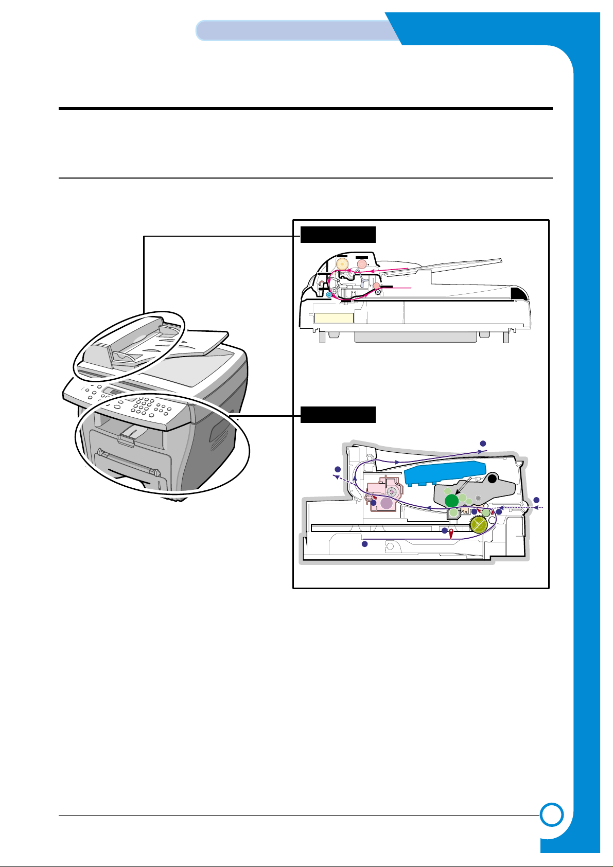
6.1 Paper path
Scanner Part
PTL
P
I
C
K
/
R
PR
CR
DR
SR
TR FR
OPC
L S U
Fuser
Toner Cartridge
1
2
3
4
5
6
8
7
Sensor-DocSensor-Doc
ADF-Roller
Pickup-Roller
Exit-Roller
Doc-Paper(30Sheets)
ADF-Idle Roller
Sensor-Regi
Feed-Roller
CCD-Module
White-SheetWhite-Sheet
Sensor-Regi
Sensor-ScanSensor-Scan
Engine Part
Page 2
6-2
ALIGNMENT & ADJUSTMENTS
Service
Manual
June 2003 WorkCentre PE16
6.1.1 Copy & Scan Document Path
6.1.2 Printer Paper Path
1) After receiving print job, the printer feeds the printing paper from the cassette or manual feeder.
2) The fed paper passes the paper feeding sensor. (Jam 0 occurs if the sensor is not operated after certain
time passes)
3) The paper passes the paper feeding sensor moving to the paper exit sensor via printing process. (Jam
1 occurs if the sensor is not operated after a certain time passes)
4) The paper passed the paper exit sensor moving out from the set. (Jam 2 occurs if the sensor is still
operated after a certain time passes.)
Scanner Part
CCD-Module
White-SheetWhite-Sheet
1
2
3
4
8
5
6
7
5
6
7
Sensor - Scan
Sensor - Regi
Feed Roller
8
Exit Roller
1
2
3
4
Doc. Paper (30 Sheets)
Pickup Roller
ADF Roller
Sensor - Doc.
Engine Part
1
2
3
4
Paper Input (Cassette)
Paper Input (Manual Feeder)
Paper Out (Face Down)
5
6
7
Paper Empty Sensor (Cassette)
Paper Feeding Sensor
Paper Exit Sensor
Paper Empty Sensor (Manual)
PTL
Page 3
6-3
ALIGNMENT & ADJUSTMENTS
Service
Manual
WorkCentre PE16 June 2003
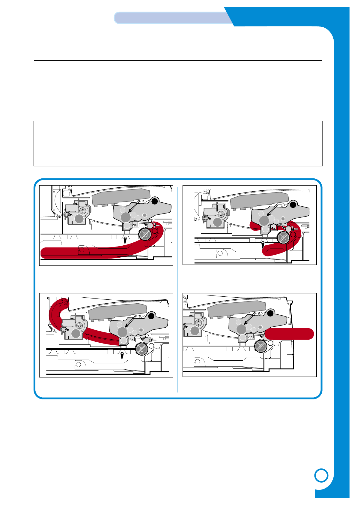
6.2 Clearing Paper Jams
Occasionally, paper can be jammed during a print job. Some of the causes include:
• The tray is loaded improperly or overfilled.
• The tray has been pulled out during a print job.
• The front cover has been opened during a print job.
• Paper was used that does not meet paper specifications.
• Paper that is outside of the supported size range was used.
If a paper jam occurs, the On Line/Error LED on the control panel lights red. Find and remove the
jammed paper. If you don’t see the paper, open the covers.
Do not use a tweezers or a sharp metal tool when removing a jam.
The covering of a metal part can be removed which can cause an electric leakage.
Paper Jam0
PTL
P
I
C
K
/
R
PR
CR
DR
SR
TR FR
Empty Sensor
OPC
L S U
Fuser
Toner Cartridge
EXIT
Sensor
Feed
Sensor
MP Sensor
Paper Jam1
PTL
P
I
C
K
/
R
PR
CR
DR
SR
TR FR
Empty Sensor
OPC
L S U
Fuser
Toner Cartridge
EXIT
Sensor
Feed
Sensor
MP Sensor
Paper Jam2
PTL
P
I
C
K
/
R
PR
CR
DR
SR
TR FR
Empty Sensor
OPC
L S U
Fuser
Toner Cartridge
EXIT
Sensor
Feed
Sensor
MP Sensor
Bypass Jam
L S U
Fuser
EXIT
PR
Sensor
Empty Sensor
CR
DR
OPC
SR
PTL
TR FR
Toner Cartridge
MP Sensor
Feed
Sensor
R
/
K
C
I
P
Page 4
6-4
ALIGNMENT & ADJUSTMENTS
Service
Manual
June 2003 WorkCentre PE16
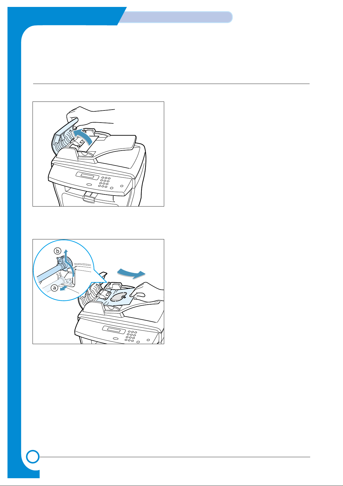
6.2.1 Clearing Document Jams
If a document jams while it is feeding through the ADF (Automatic Document Feeder),“DOCUMENT JAM ” appears on
the display.
6.2.1.1 Input Misfeed
1) Open the ADF top cover.
2) Pull the document gently to the right and out of the
ADF.
3) Close the ADF top cover.Then load the documents
back into the ADF.
NOTE : To prevent document jams,use the document
glass for the thick,thin or mixed documents.
Page 5
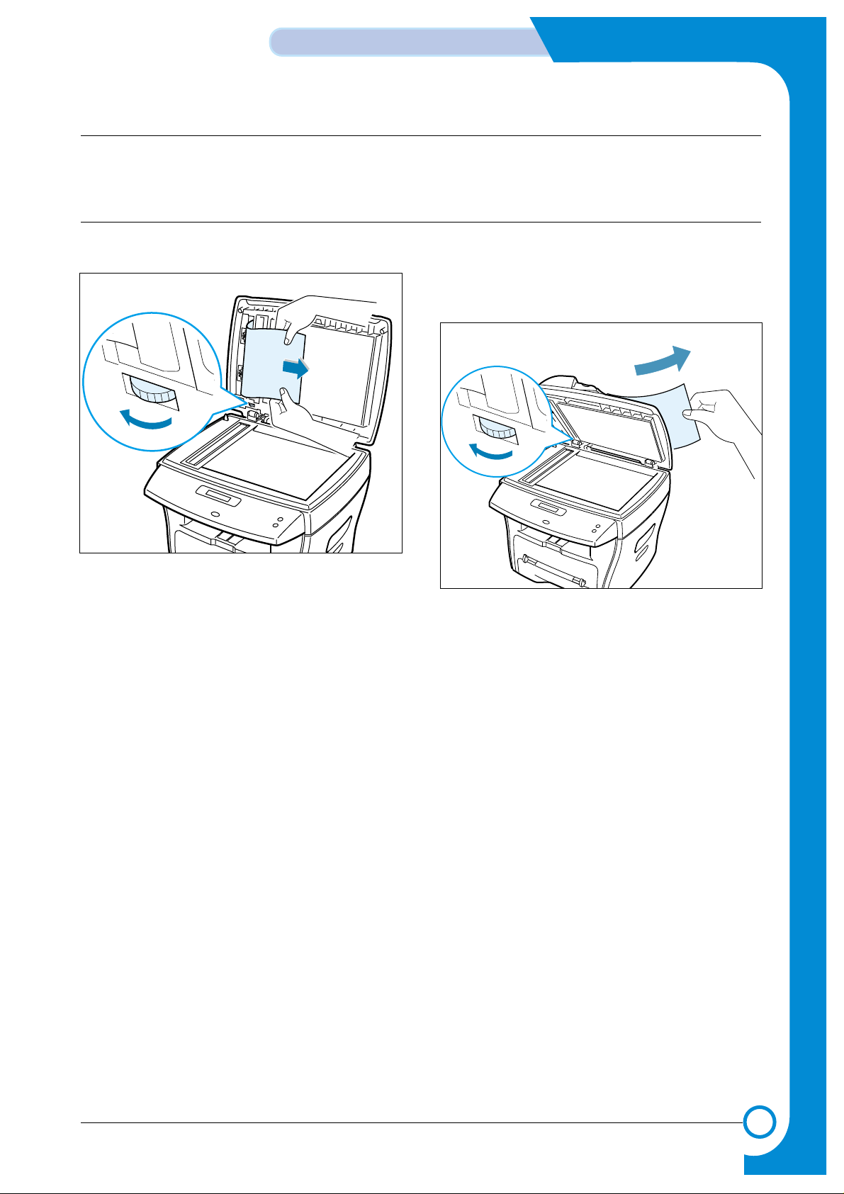
1) Open the document cover. 2) Turn the release knob so that you can easily remove
the misfed document,and remove the document from
the ADF or the feed area by carefully pulling it
towards the right by using both hands.
3) Close the document cover.Then load the documents
back into the ADF.
6-5
ALIGNMENT & ADJUSTMENTS
Service
Manual
WorkCentre PE16 June 2003
6.2.1.2 Exit Misfeed
1) Open the document cover and turn the release knob to remove the misfed documents from the exit area.
2) Close the document cover.Then load the documents back into the ADF.
6.2.1.3 Roller Misfeed
Page 6
6-6
ALIGNMENT & ADJUSTMENTS
Service
Manual
June 2003 WorkCentre PE16
6.2.2 Clearing Paper Jams
If paper jams occur,“PAPER JAM ” appears on the display. Refer to the table below to locate and clear the paper jam.
PAPER JAM 0 : In the paper feed area
PAPER JAM 2 : In the paper exit area
PAPER JAM 1 : In the fuser area or around the toner cartridge
BYPASS JAM : In the Bypass tray
Follow the steps below to clear a jam.To avoid tearing the paper, pull the jammed paper out gently and slowly.
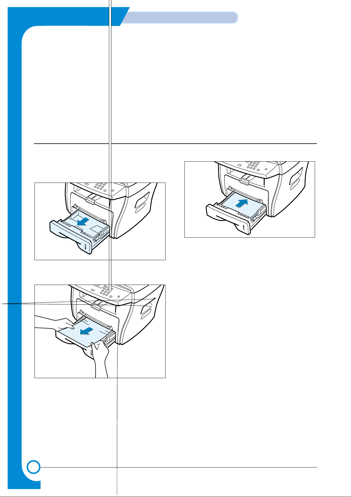
6.2.2.1 JAM0 (In the Paper Feed Area)
1) Open and close the front cover.The jammed paper
automatically exits the machine.
If the paper does not exit,continue to Step 2.
2 Pull the paper tray open.
3) Remove the jammed paper by gently pulling it
straight out.
If there is any resistance when you pull the
paper or the paper is not seen in this area,skip
to the fuser area around the toner cartridge
4) Insert the paper tray into the machine until it snaps
into place.
5) Open and close the front cover to resume printing.
Page 7

6-7
ALIGNMENT & ADJUSTMENTS
Service
Manual
WorkCentre PE16 June 2003
6.2.2.2 JAM 2 (In the Paper Exit Area)
1) Open and close the front cover.The jammed paper
automatically exits the machine.
If the paper does not exit,continue to Step 2.
2) Gently pull the paper out of the front output tray.
3) If there is any resistance when you pull the paper or
the paper is not seen in the front output tray,open the
rear cover.
4) Remove the jammed paper by gently pulling it
straight out.
5) Close the rear cover.
6) Open and close the front cover to resume printing.
Page 8

6-8
ALIGNMENT & ADJUSTMENTS
Service
Manual
June 2003 WorkCentre PE16
6.2.2.3 JAM1 (In the Fuser Area of Around the Toner Cartridge Area)
NOTE : The fuser area is hot.Be careful when removing paper from the machine.
1) Open the front cover and remove the toner cartridge.
2) Remove the jammed paper by gently pulling it
straight out.
3) Replace the toner cartridge and close the front cover.
Printing automatically resumes.
Page 9

6-9
ALIGNMENT & ADJUSTMENTS
Service
Manual
WorkCentre PE16 June 2003
6.2.2.4 BYPASS JAM (In the Bypass Tray)
“BYPASS JAM ” appears on the display when the machine does not detect paper in the Bypass tray due to no paper or
improper paper loading when you try to print using the Bypass tray.
“BYPASS JAM ” also may occur when the paper is not properly fed into the machine through the Bypass tray.In that
case,pull the paper out of the machine.
6.2.2.5 Tips for Avoiding Paper Jams
By selecting the correct paper types,most paper jams can be avoided. If a paper jam occurs, follow the steps outlined in
“Clearing Paper Jams ”
• Follow the procedures in “Loading Paper ” .Ensure that the adjustable guides are positioned correctly.
• Do not overload the paper tray.Ensure that the paper is below the paper capacity mark on the inside wall of
the paper tray.
• Do not remove the paper from the tray while printing.
• Flex, fan and straighten the paper before loading.
• Do not use creased, damp or highly curled paper.
• Do not mix paper types in the paper tray.
• Use only recommended print materials. See “Paper Specifications ”
• Ensure that the recommended print side is facing down when loading paper in the paper tray and facing up in
the Bypass tray.
Page 10

6-10
ALIGNMENT & ADJUSTMENTS
Service
Manual
June 2003 WorkCentre PE16
1.Paper Setting
Paper Tray
Paper Size
2.Copy Setup
Change Default
Timeout
6.Reports
System Data
8.Machine Setup
Language
Power Save
CCD Power Save
USB Mode
9.Maintenance
Clean Drum
Clear Memory
6.3 User Mode(SCX-4116 & SCX-4016)
The table in the bellow explains the possible setting functions by user. The details about the ways to use
are explained in the user manual.
In the service manual, the items are about the possible set-up by user.
Page 11

6-10
ALIGNMENT & ADJUSTMENTS
Service
Manual
June 2003 WorkCentre PE16
1.Paper Setting
Paper Tray
Paper Size
2.Copy Setup
Change Default
Timeout
3.Fax Setup
Receive Mode
Ring to Answer
Contrast
Redial Term
Redials
MSG Confirm.
Auto Report
Auto Reduction
Discard Size
4.Fax Feature
Delay Fax
Priority Fax
Add / Cancel
5.Advanced Fax
Send Forward
RCV Forward
Toll Save
Junk Fax Setup
Secure Receive
Prefix Dial No
Stamp RCV Name
ECM Mode
6.Reports
Phone Book
Send Report
RCV Report
System Data
Scheduled Jobs
Tx Confirm.
Junk Fax List
7.Sound/Volume
Speaker
Ringer
Key Sound
Alarm sound
8.Machine Setup
Machine ID
Date&Time
Clock Mode
Language
Power Save
CCD Power Save
USB Mode
9.Maintenance
Clean Drum
Notify toner
Clear Memory
6.3 User Mode
The table in the bellow explains the possible setting functions by user. The details about the ways to use
are explained in the user manual.
In the service manual, the items are about the possible set-up by user.
Page 12

6-11
ALIGNMENT & ADJUSTMENTS
Service
Manual
WorkCentre PE16 June 2003
6.4 Tech Mode
6.4.1 How to Enter Tech Mode
In service (tech) mode, the technician can check the machine and perform various test to isolate the cause
of a malfunction.
While in Tech mode, the machine still performs all normal operations.
To enter the Tech mode
To enter the Tech mode, press in sequence, and the LCD
briefly displays ‘TECH’, the machine has entered service (tech) mode.
6.4.2 Setting-up System in Tech Mode
WorkCentre PE16
Page 13

6-12
ALIGNMENT & ADJUSTMENTS
Service
Manual
June 2003 WorkCentre PE16
6.4.3 Data Setup
SEND LEVEL
You can set the level of the transmission signal. Typically, the Tx level should be under -12 dBm.
Caution : The Send Fax Level is set at the best condition in the shipment from factory. Never change settings
arbitrarily .
DIAL MODE
This function can choose dial method.
*Default : Dial(Tone/Pulse)
MODEM SPEED
You can set the maximum modem speed.
Communication is done with modem speed automatically set at lower speed when communicating with a slower speed modem since communication is done on the standard of the side where modem speed is low for
transmission/reception. It is best set 33.6Kbps as default setting.
ERROR RATE
When the error rate is about exceed the set value, the Baud rate automatically adjusts to 2400 bps.
This ensures that the error rate remains below the set value.
You can select the rate between 5% and 10%.
CLEAR ALL MEMORY
The function resets the system to factory default settings.
This function is used to reset the system to the initial value when the product is functioning abnormally . All the values are returned to the default values, and all the information, which was set by
the user, will be erased.
< Method >
1. Select the [MEMORY CLEAR] at the TECH MODE.
2. Push the ENTER button.
3. Select you country. (There are four country groups. Refer to the table below.)
4. Push the ENTER button then it will clear all memory.
NOTICE : Always perform a memory clear after replacing the main board. Otherwise, the system
may not operate properly.
Country Group USA/Canada UK Russia Southafrica
USA/Canada UK Russia Southafrica
Mexico Germany india
Brazil France Oman
Italy Poland
Spain Bangladesh
Austria Kuwait
Netherlands Moroco
Belgium Algeria
Country Portugal Pakistan
Sweden UAE
Norway Bahrain
Denmark Srilanka
Finland SaudiArabia
Switzerland Chile
Greece Peru
Ireland Argentina
Turkey Hungary
Romania
Bulgaria
Czech
Page 14

6-14
ALIGNMENT & ADJUSTMENTS
Service
Manual
June 2003 WorkCentre PE16
FLASH UPGRADE
The Firmware Upgrade function and has two methods, Local and Remote.
(1) Local Machine
• RCP(Remote Control Panel) mode
This method is for Parallel Port.or USB Port Connect to PC and activate RCP(Remote Control Panel) to
upgrade the Firmware.
< Method >
How to Update Firmware using RCP
1. Connect PC and Printer with Parallel Cable or USB Cable.
2. Execute RCP and select Firmware Update.
3. Search Firmware file to update with Browse Icon.
4. Click Update icon, firmware file is transmitted to Printer automatically and printer is initialized when it finished.
5. Click Refresh icon and check what is updated.
• DOS Command mode
This method is just for Parallel Port. Connect to PC with Parallel cable and enter DOS Command to upgrade
the Firmware.
< Method >
1. The first of all, need the files : down.bat, down_com.bin, fprt.exe, and Rom File: file name for
upgrade.Save the files in the same folder.
2. In the DOS, input as below and push the enter key. Then, it will be automatically upgraded.
3. There are two commands for the conditions of product.
* When the product is in idle condition down "rom file"
* When the product is in Ready condition (TECH MODE → MAINTENANCE→ FLASH UPGRADE→ LOCAL)
fprt "rom file"
4. Do not turn off the power while upgrading process.
(2) Remote FAX
This is a function that a fax with the latest firmware sends files to a fax in long distance through telephone line.
< Method >
1. Operate a fax with the latest firmware to prepare it being upgrade.
(TECH MODE →MAINTENANCE→FLASH UPGRADE→REMOTE)
2. Input the fax number, which needs to be upgraded.
(Several faxes can be upgrade at the same time. In this case, enter the each fax number.)
3. After push the enter button, send the firmware file by calling to the appointed number.
(Around 10~15 minutes needs to send the file.)
< Caution >
1. sending and receiving fax must be the same model.
2. Asending fax must be set up as ECM mode, and a receiving memory must be set up as 100%.
If not, the function operates abnormally.
Page 15

6-15
ALIGNMENT & ADJUSTMENTS
Service
Manual
WorkCentre PE16 June 2003
6.5.4 Machine Test
SWITCH TEST
Use this feature to test all keys on the operation control panel. The result is displayed on the LCD
window each time you press a key.
MODEM TEST
Use this feature to hear various transmission signals to the telephone line from the modem and to
check the modem. If no transmission signal sound is heard, it means the modem part of the main
board malfunctioned.
DRAM TEST
Use this feature to test the machine's DRAM. The result appears in the LCD display.
If all memory is working normally, the LCD shows << O K >>
ROM TEST
Use this feature to test the machine'S ROM. The result and the software version appear in the LCD
display.
• FLASH VER : 1.00 V
• ENGINE VER :1.00V
PATTERN TEST
Using this pattern printout, you can check if the printer mechanism is functioning properly.
It is needed in the production progress. Service person doesn't need to use it.
SHADING TEST
The function is to get the optimum scan quality by the specific character of the CCD(Charge
Coupled Device). If the copy image quality is poor, perform this function to check the condition
CCD unit.
< Method >
1. Select the [ADJUST SHADING] at the
TECH MODE.
2. Push the SET UP button then an image
will be scanned.
3. After the scan, CCD SHADING PROFILE will be print out.
4. If the printed image is different to the
image, the CCD is defect.
NOTICE : When you test CCD, make sure
that the cover is closed.
Page 16

6-16
ALIGNMENT & ADJUSTMENTS
Service
Manual
June 2003 WorkCentre PE16
6.5.5 Report
PROTOCOL LIST
This list shows the sequence of the CCITT group 3 T.30 protocol during the most recent sending or receiving
operation. Use this list to check for send and receive errors. If a communication error occurs while the machine
is in TECH mode, the protocol list will print automatically.
SYSTEM DATA
This list provides a list of the user system data settings and tech mode settings.
Page 17

6-17
ALIGNMENT & ADJUSTMENTS
Service
Manual
WorkCentre PE16 June 2003
6.6 Engine Test Mode
The Engine Tests Mode supplies useful functions to check the condition of the engine. It tests the condition
of each device and displays the result of the test on the LCD. It is classified into 5 functions )0~4), and are
shown below.
6.6.1 To enter the Engine Test Mode
To enter the Engine Test mode
Press in sequence, and the LCD briefly displays
‘Engine Test’, the machine has entered Engine Test Mode.
6.6.2 Diagnostic
NO. Sub No. Engine test Remark
0 1 Motor Test 1 : On, 2 : Off
2 PickUp Test 1 : On, 2 : Off
3 Fan Test 1 : On, 2 : Off
4 Manual Clt Test 1 : On, 2 : Off
5 PTL Test 1 : On, 2 : Off
1 1 LSU Motor Test 1 : On, 2 : Off
2 LSU Hsync Test 1 : On, 2 : Off
3 LD Test 1 : On, 2 : Off
2 1 Feed Sen Test Check : Check Start
Next : Next Sensor Check
2 Exit Sen Test Check : Check Start
Next : Next Sensor Check
3 Cover Sen Test Check : Check Start
Next : Next Sensor Check
4 Empty Sen Test Check : Check Start
Next : Next Sensor Check
5 Manual Sen Text Check : Check Start
Next : Next Sensor Check
3 1 Therm ADC 180 1 : On, 2 : Off (maintain the fusing temp. 80C)
2 Therm ADC 140 1 : On, 2 : Off (maintain the fusing temp. 135C)
3 Therm ADC 120 1 : On, 2 : Off (maintain the fusing temp. 160C)
4 Therm ADC 100 1 : On, 2 : Off (maintain the fusing temp. 191C)
4 1 MHV Test 1 : On, 2 : Off (-1550V ± 50V)
2 Dev Bias Test 1 : On, 2 : Off (-430V ± 20V)
3 THV EN/NEG Test 1 : On, 2 : Off (-1000V +300V/-150V)
4 THV ON (1300V) 1 : On, 2 : Off (+1300V ± 20V)
5 THV ADC 1300V 1 : On, 2 : Off (ADC Value : 101 ±5)
6 THV ADC 600V~3500V 1 : On, 2 : Off (Compare each ADC Value)
Page 18

6-18
ALIGNMENT & ADJUSTMENTS
Service
Manual
June 2003 WorkCentre PE16
6.7 Identify Sale Date
This function confirms the date that consumer bought product and used the product for the first time.
When the consumer first operate the machine, it will start a scan and page count.
The time the machine was first used is remembered.
These settings are are remembered after memory delete (Clear All Memory).
< Method >
Press MENU, #, 1, 9, 3, # in sequence.Firmware version is displayed on LCD.
Press 1( in the number keypad) : The LCD display shows "Updated date"
Press 2( in the number keypad) : The LCD display shows "Product first use date"
Page 19

6-19
ALIGNMENT & ADJUSTMENTS
Service
Manual
WorkCentre PE16 June 2003
6.8 Consumables and Replacement Parts
The cycle period outlined below is a general guideline for maintenance.
The example list is for an average usage of 50 transmitted and received documents per day.
Environmental conditions and actual use will may vary.
The cycle period given below is for reference only.
COMPONENT REPLACEMENT CYCLE
ADF Rubber 20,000 Pages
ADF Roller 60,000 Pages
Pick-up Roller 60,000 Pages
Friction Pad 60,000 Pages
Transfer Roller 60,000 Pages
Fuser 60,000 Pages
Toner Cartridge 3,000 Pages (A4 IDC 5% Pattern)
Page 20

6-20
ALIGNMENT & ADJUSTMENTS
Service
Manual
June 2003 WorkCentre PE16
6.9 Abnormal Image Printing and Defective Roller
If abnormal image prints periodically, check the parts shown below.
No Roller Abnormal image period Kind of abnormal image
1 OPC Drum 75.5mm White spot, Block spot
2 Charge Roller 37.7mm Black spot
3 Supply Roller 37.0mm Horizontal density band
4 Develop Roller 35.2mm Horizontal density band
5 Transfer Roller 45.3mm Black side contamination/transfer fault
6 Heat Roller 66.3mm Black spot and fuser ghost
7 Pressure Roller 75.5mm Black side contamination
1
2
3
4
OPC Drum
Charge Roller
Supply Roller
Developing Roller
5
6
7
Transfer Roller
Heat Roller
Pressure Roller
L S U
Fuser
PR
CR
OPC
TR FR
Toner Cartridge
DR
SR
PTL
MP Sensor
R
/
K
C
I
P
Page 21

6-21
ALIGNMENT & ADJUSTMENTS
Service
Manual
WorkCentre PE16 June 2003
6.10 Error Messages
The display on the front panel shows the messages to indicate the printer ’s status or errors.Refer to the tables below to
understand the message ’s meaning and clear the problem if necessary.Messages and their meanings are listed in
alphabetical order,with numbered messages following.
BYPASS JAM
Meaning : When the machine detected the non-feeding from BYPASS Tray.
Solution : Open the side Cover and clear the jam.
COMM. ERROR
Meaning : A problem with the facsimile communications has occurred.
Solution : Try again.
DOCUMENT JAM
Meaning : Loaded document has Jammed in the feeder When Document Jam aeeurred at AD
Solution : Clear the document Jam.
DOOR OPEN
Meaning : The side cover is not securely latched.
Solution : Clear the cover until it clicks in place.
DRUM WARNING
Meaning : When the machine has encountered the drum life,14000 print pages.
Solution : Use little more change if “REPLACE DRUM” is marked in LCD window.
GROUP NOT A VAILABLE
Meaning : You have tried to select a group location where only a single location number can be used, such
as when adding locations for a multi-dial operation.
Solution : Try again, check location for group.
Heating Error
Meaning : During operation, Temperature does not go up.
Solution : Check thermister contact point & Heating Lamp.
LINE BUSY
Meaning : The remote FAX didn’t answer
Solution : Try again.
LINE ERROR
Meaning : Your unit cannot connect with the remote machine, or has lost contact because of a problem on
the phone line. When the machine has a problem in cause of fax data reception step
Solution : Try again. If failure persists, wait an hour or so for the line to clear then try again.
LOAD DOCUMENT
Meaning : You have attempted to set up a sending operation with no document loaded.
Load a document and try again.
Solution : Try again. Make sure the remote machine is OK.
MEMORY FULL
Meaning : The memory has become full.
Solution : Either delete unnecessary documents, or retransmit after more memory becomes available, or
split the transmission into more than one operation.
Page 22

6-22
ALIGNMENT & ADJUSTMENTS
Service
Manual
June 2003 WorkCentre PE16
NO ANSWER
Meaning : The remote machine was not answered after all the redial attempts.
Solution : Try again. Make sure the remote machine is OK.
NO CARTRIDGE
Meaning : When the machine detected the toner cartridge has not been installed.
Solution : Install the Cartridge.
NO. NOT ASSIGNED
Meaning : The speed dial location you tried to use has no number assigned to it.
Solution : Dial the number manually with the keypad, or assign the number.
NO PAPER [ADD PAPER]
Meaning : The recording paper has run out. The printer system stops.
Solution : Load the recording paper in the paper feeder.
OPEN HEAT ERROR
Meaning : Thermister does not connected to main board or contact point is not coupled tightly in power on.
Solution : Check thermister contact point, Heating Camp & Thermostat.
OVERHEA T
Meaning : The printer part has overheated.
Solution : Your unit will automatically return to the standby mode when it cools down to normal operating
temperature. If failure persists, call service.
PAPER JAM 0
OPEN/CLOSE DOOR
Meaning : Recording paper has jammed in paper feeding area. Recording paper is jammed in pick-up unit
Solution : Press STOP and clear the jam.
PAPER JAM 1/2
OPEN/CLOSE DOOR
Meaning : Recording paper has jammed inside the unit. Recording paper has jammed in paper exit unit.
Solution : Clear the jam.
RETRY REDIAL?
Meaning : The machine is waiting for the programmed interval to automatically redial.
Solution : You can press START to immediately redial, or STOP to cancel the redial operation.
TONER EMPTY
Meaning : When the machine has encountered the Toner Empty.
Solution : Replace the Toner Cartridge.
TONER LOW
Meaning : Toner may be low
Solution : Toner may be unevenly distributed. Remove the toner cartridge and shake it gently to evenly dis-
tribute the toner. Then replace the toner cartridge.
Scanner Locked
Meaning : Scanner is locked by locker.
Solution : Check locker. Connect the Flat-Cable.
 Loading...