

Samsung SCC-643AP User Manual

Combi Dome Camera
SCC-643(P)
Owner’s Instructions
Benutzerhandbuch
Manuel d’instruction
Manual del usuario
Istruzioni per l’uso
E
D
F
Es
I
Part : AB68-00357A
Printed in Korea

Safety Precautions
The purpose of this information is to ensure proper use of this product to
prevent danger or damage to property. Please be sure to observe all
precautions.
* The precautions are divided into "Warnings" and "Cautions" as
distinguished below:
Warning: Ignoring this warning may result in death or serious injury.
Caution: Ignoring this caution may result in injury or damage to property.
Warning instructions alert you to
a potential risk of death
or serious injury.
Caution instructions alert you to the
potential risk of injury or
damage to property.
Warning
1. Be sure to use only the supplied adapter.
(Using an adapter other than the one supplied may cause fire, electrical
shock, or damage to the product.)
2. When connecting the power supply and signal wires, check the external
connection terminals before connecting them. Connect the alarm signal
wires to the alarm terminals, the AC adapter to the AC power input
receptacle, and the DC adapter to the DC power input, making sure that
the correct polarity is observed.
(Connecting the power supply incorrectly may cause fire, electrical shock,
or damage to the product.)
3. Do not connect multiple cameras to a single adapter.
(Exceeding the capacity may cause abnormal heat generation or fire.)
(A falling camera may cause personal injury.)
4. Securely plug the power cord into the power receptacle.
(Insecure connection may cause fire.)
5. When installing the camera on a wall or ceiling, fasten it securely and
firmly. (A falling camera may cause personal injury.)
6. Do not place conductive objects (e.g., screwdrivers, coins, and metal
things) or containers filled with water on top of the camera. (Doing so may
cause personal injury due to fire, electrical shock, or falling objects.)
7. Do not install the unit in humid, dusty, or sooty locations.
(Doing so may cause fire or electrical shock.)
8. If any unusual smells or smoke come from the unit, stop using the product.
In such case, immediately disconnect the power source and contact the
service center. (Continued use in such a condition may cause fire or
electrical shock.)
9. If this product fails to operate normally, contact the store of purchase or
your nearest service center. Never disassemble or modify this product in
any way. (SAMSUNG is not liable for problems caused by unauthorized
modifications or attempted repair.)
10. When cleaning, do not spray water directly onto parts of the product.
(Doing so may cause fire or electrical shock.)
Wipe the surface with a dry cloth. Never use detergents or chemical
cleaners on the product, as this may result in discoloration of surface or
cause damage to the finish.
Caution
1. Do not drop objects on the product or apply strong shock to it. Keep away
from a location subject to excessive vibration or magnetic interference.
2. Do not install in a location subject to high temperature (over
temperature (below 14°F
(Doing so may cause fire or electrical shock.)
3. Avoid a location which is exposed to direct sunlight, or near heat sources
such as heaters or radiators.
(Neglecting to do so may result in a risk of fire.)
4. If you want to relocate the already installed product, be sure to turn off the
power and then move or reinstall it.
5. Install in a well-ventilated location.
6. Remove the power plug from the outlet when there is a lightning storm.
(Neglecting to do so may cause fire or damage to the product.)
), or high humidity.
122°F), low
E

Before Usage
This is a basic instruction manual for the SCC-643(P) user.
It contains all the instructions needed to use the SCC-643(P) from
a simple introduction of the control locations and functions of the
SCC-643(P) to installation methods in the set up menu.
Approval of Standards
We recommend all users of the SCC-643(P) from the advanced
user who has used similar cameras before to the general user to
read the instruction manual before using.
The most frequently used feature in the SCC-643(P) would be the
SCC-643(P) Setup Menu.
The SCC-643(P) Setup Menu is explained in detailed in "Chapter
3 Setup Menu Overview".
The instructional manual is best used when read from beginning
to end, but for users wanting to read only the part they need here
are the Chapter summaries.
"Chapter 1 SCC-643(P) Overview" includes a brief introduction
of the SCC-643(P), part names and functions, and Switch
Settings.
"Chapter 2 SCC-643(P) Installation" explains the installation
procedures of the SCC-643(P) and provides preparation and
installation environment requirements.
"Chapter 3 Setup Menu Overview" presents the structure of the
Setup menu for the SCC-643(P) including a detailed explanation
of the functions performed in each submenu.
E
Note: This equipment has been tested and found to comply with the limits for a Class B
digital device, pursuant to part 15 of the FCC Rules. These limits are designed to provide
reasonable protection against harmful interface in a residential installation. This equipment
generates, uses and can radiate radio frequency energy and, if not installed and used in
accordance with the instructions, may cause harmful interference to radio communications.
However, there is no guarantee that interference will not occur in a particular installation.
If this equipment does cause harmful interference to radio or television reception, which can
be determined by turning the equipment off and on, the user is encouraged to try to correct
the interference by one or more of the following measures:
- Reorient of relocate the receiving antenna.
- Increase the separation between the equipment and receiver.
- Connect the equipment into an outlet on a circuit different from that to which
the receiver is connected.
- Consult the dealer or an experienced radio TV technician for help.
"Appendix SCC-643(P) Product Specifications" contains
product specifications of the SCC-643(P) in itemized categories.
1-1
1-2

Table of contents
Before Usage --------------------------------------------------------------------------------------1-1
Chapter 1 SCC-643(P) Overview -----------------------------------------------------------1-5
SCC-643(P) Introduction---------------------------------------------------------1-6
SCC-643(P)Locations of Control-----------------------------------------------1-7
SCC-643(P) FRONT --------------------------------------------------------------1-7
SCC-643(P) BACK ----------------------------------------------------------------1-8
ADAPTER CONNECTION-------------------------------------------------------1-9
INITIAL SETTING----------------------------------------------------------------1-10
Setting RS-422A/RS-485 termination---------------------------------------1-11
SWITCH SETTING --------------------------------------------------------------1-12
Chapter 2 SCC-643(P) Installation---------------------------------------------------------2-1
Before Installing
Preparing the Cables
Cable Connection
Installing SCC-643(P)
Installing the Camera
Chapter 3 Setup Menu Overview-----------------------------------------------------------3-1
Structure of the Setup Menu
1. CAMERA SET MENU ---------------------------------------------------------3-4
- CAMERA ID--------------------------------------------------------------------3-4
- V-SYNC -------------------------------------------------------------------------3-4
- COLOR/BW--------------------------------------------------------------------3-5
- ZOOM SPEED ----------------------------------------------------------------3-6
- MOTION DET------------------------------------------------------------------3-6
- EXIT------------------------------------------------------------------------------3-7
2. VIDEO SET MENU-------------------------------------------------------------3-7
- IRIS-------------------------------------------------------------------------------3-7
- ALC-------------------------------------------------------------------------------3-8
- BLC-------------------------------------------------------------------------------3-8
- MANU----------------------------------------------------------------------------3-9
- SHUTTER ----------------------------------------------------------------------3-9
-------------------------------------------------------------------2-2
-----------------------------------------------------------2-3
-----------------------------------------------------------------2-4
-----------------------------------------------------------2-5
------------------------------------------------------------2-8
--------------------------------------------------3-2
- AGC ----------------------------------------------------------------------------3-10
- S.S------------------------------------------------------------------------------3-10
- SLOW--------------------------------------------------------------------------3-11
- NORMAL----------------------------------------------------------------------3-11
- FAST ---------------------------------------------------------------------------3-11
- F.F ------------------------------------------------------------------------------3-11
- WHITE BAL-------------------------------------------------------------------3-12
- SPECIAL----------------------------------------------------------------------3-14
- AUTO FOCUS---------------------------------------------------------------3-15
- D-ZOOM-----------------------------------------------------------------------3-15
- EXIT ----------------------------------------------------------------------------3-15
3. PRESET-------------------------------------------------------------------------3-16
4. AUTO MODE-------------------------------------------------------------------3-18
- AUTO PAN -------------------------------------------------------------------3-18
- PATTERN---------------------------------------------------------------------3-19
5. ALARM SET--------------------------------------------------------------------3-20
6. OTHER SET--------------------------------------------------------------------3-22
Appendix Product specifications --------------------------------------------------------3-25
E
1-3
1-4

Chapter 1 SCC-643(P) Overview
In this chapter we will briefly introduce the SCC-643(P) and show
main functions, locations of control and Switch Setting.
SCC-643(P) Introduction
The SCC-643(P) is the best performing zoom lens integrated
surveillance camera. It can be used with CCTV in banks or
companies to provide high level of security.
The SCC-643(P) is a high quality surveillance camera using x22
zoom lens and digital zoom IC, it can catch clear images up to
220 times.
The SCC-643(P) is a multifunction camera that is equipped with all
of the key functions of the existing surveillance cameras:
- Low-Light Surveillance function that enables image
capture even under extremely low light conditions.
- White Balance function that provides accurate color
rendition under any light conditions.
- BLC function that enables effective back light
compensation even under a spotlight or a very bright
incident light.
- Auto-Focus function that automatically tracks and focuses
on the moving subject.
- Privacy Zone function that hides certain area of the screen
from view to protect individual privacy.
- COLOR/BW function that automatically switches to the BW
(Black and White) mode to increase the camera's
sensitivity at night or under low light level conditions.
E
1-5
The SCC-643(P) uses an Alarm function for alert situations and
moving camera in the direction you want, ZOOM-IN and
ZOOM-OUT functions can be remote controlled.
1-6
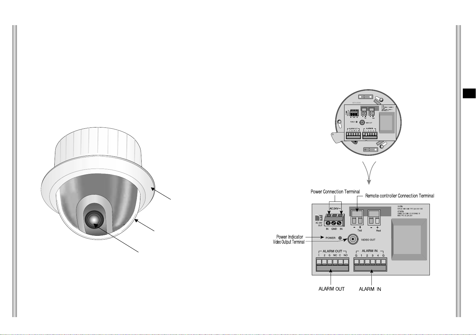
Locations of Control
FRONT
BACK
E
COVER BODY
COVER DOME
ZOOM LENS
1-7
1-8

SW501
SW500
SEE INSTRUCTION MANUAL
ADAPTER CONNECTION
INITIAL SETTING
CAMERA ADDRESS SETUP
Dip Switch setting is same as the following example:
EX) CAMERA ADDR: When it's number 1, set as follows.
SCC-643(P) Adapter BOARD
1 2 3 4 5 6 7 8
ON
OFF
SW500
Setting communication Protocol
Use number 5~8 PIN of SW501 to set communication Protocol.
PIN
PIN5 PIN6 PIN7 PIN8
Comp
A OFF OFF OFF OFF
B ON OFF OFF OFF
C OFF ON OFF OFF
D ON ON OFF OFF
E OFF OFF ON OFF
F ON OFF ON OFF
G OFF ON ON OFF
H ON ON ON OFF
I OFF OFF OFF ON
J ON OFF OFF ON
K OFF ON OFF ON
L ON ON OFF ON
M OFF OFF ON ON
N ON OFF ON ON
O OFF ON ON ON
PONONONON
A : SAMSUNG(SSC-1000)HALF
B : SAMSUNG(SSC-1000)FULL
(BOTTOM VIEW)
Baud Rate Setting
Use PIN 3 and 4 of SW501.
1 2 3 4 5 6 7 8
ON
OFF
SW 501
E
1-9
BAUD RATE
4800 BPS
9600 BPS
19200 BPS
38400 BPS
PIN 3
ON
OFF
ON
OFF
PIN 4
ON
ON
OFF
OFF
1-10

Setting RS-422A/RS-485 termination
SWITCH SETTING
SW 501
As it is shown in the structure map, when Controller and RS-422A/RS-485
is connected it should be terminated according to the Cable feature of
impedance on the each end of the transmitting line to transfer the signals in
long distance by controlling the reflection of the signals to the lowest.
Division
<RS-485 Half Duplex Organization>
n < 128
Termination
SW1-ON
Termination: using numbers 1 and 2 PIN, turn to ON and it will be terminated.
n < 128
Division
SW1-ON
Division
<RS-422A/RS-485 Full Duplex Organization>
SW2-ON
Receiver Address
0
1
2
3
4
5
6
7
8
9
10
11
12
13
14
15
16
17
18
19
20
21
22
23
24
25
26
27
28
29
30
31
32
33
34
35
36
37
38
39
40
41
42
43
44
45
46
47
48
49
50
51
52
53
54
55
SW500-1
OFF
ON
OFF
ON
OFF
ON
OFF
ON
OFF
ON
OFF
ON
OFF
ON
OFF
ON
OFF
ON
OFF
ON
OFF
ON
OFF
ON
OFF
ON
OFF
ON
OFF
ON
OFF
ON
OFF
ON
OFF
ON
OFF
ON
OFF
ON
OFF
ON
OFF
ON
OFF
ON
OFF
ON
OFF
ON
OFF
ON
OFF
ON
OFF
ON
SW500-2
OFF
OFF
ON
ON
OFF
OFF
ON
ON
OFF
OFF
ON
ON
OFF
OFF
ON
ON
OFF
OFF
ON
ON
OFF
OFF
ON
ON
OFF
OFF
ON
ON
OFF
OFF
ON
ON
OFF
OFF
ON
ON
OFF
OFF
ON
ON
OFF
OFF
ON
ON
OFF
OFF
ON
ON
OFF
OFF
ON
ON
OFF
OFF
ON
ON
SW500-3
OFF
OFF
OFF
OFF
ON
ON
ON
ON
OFF
OFF
OFF
OFF
ON
ON
ON
ON
OFF
OFF
OFF
OFF
ON
ON
ON
ON
OFF
OFF
OFF
OFF
ON
ON
ON
ON
OFF
OFF
OFF
OFF
ON
ON
ON
ON
OFF
OFF
OFF
OFF
ON
ON
ON
ON
OFF
OFF
OFF
OFF
ON
ON
ON
ON
SW500-4
OFF
OFF
OFF
OFF
OFF
OFF
OFF
OFF
ON
ON
ON
ON
ON
ON
ON
ON
OFF
OFF
OFF
OFF
OFF
OFF
OFF
OFF
ON
ON
ON
ON
ON
ON
ON
ON
OFF
OFF
OFF
OFF
OFF
OFF
OFF
OFF
ON
ON
ON
ON
ON
ON
ON
ON
OFF
OFF
OFF
OFF
OFF
OFF
OFF
OFF
SW500-5
OFF
OFF
OFF
OFF
OFF
OFF
OFF
OFF
OFF
OFF
OFF
OFF
OFF
OFF
OFF
OFF
ON
ON
ON
ON
ON
ON
ON
ON
ON
ON
ON
ON
ON
ON
ON
ON
OFF
OFF
OFF
OFF
OFF
OFF
OFF
OFF
OFF
OFF
OFF
OFF
OFF
OFF
OFF
OFF
ON
ON
ON
ON
ON
ON
ON
ON
SW500-6
OFF
OFF
OFF
OFF
OFF
OFF
OFF
OFF
OFF
OFF
OFF
OFF
OFF
OFF
OFF
OFF
OFF
OFF
OFF
OFF
OFF
OFF
OFF
OFF
OFF
OFF
OFF
OFF
OFF
OFF
OFF
OFF
ON
ON
ON
ON
ON
ON
ON
ON
ON
ON
ON
ON
ON
ON
ON
ON
ON
ON
ON
ON
ON
ON
ON
ON
SW500-7
OFF
OFF
OFF
OFF
OFF
OFF
OFF
OFF
OFF
OFF
OFF
OFF
OFF
OFF
OFF
OFF
OFF
OFF
OFF
OFF
OFF
OFF
OFF
OFF
OFF
OFF
OFF
OFF
OFF
OFF
OFF
OFF
OFF
OFF
OFF
OFF
OFF
OFF
OFF
OFF
OFF
OFF
OFF
OFF
OFF
OFF
OFF
OFF
OFF
OFF
OFF
OFF
OFF
OFF
OFF
OFF
SW500-8
OFF
OFF
OFF
OFF
OFF
OFF
OFF
OFF
OFF
OFF
OFF
OFF
OFF
OFF
OFF
OFF
OFF
OFF
OFF
OFF
OFF
OFF
OFF
OFF
OFF
OFF
OFF
OFF
OFF
OFF
OFF
OFF
OFF
OFF
OFF
OFF
OFF
OFF
OFF
OFF
OFF
OFF
OFF
OFF
OFF
OFF
OFF
OFF
OFF
OFF
OFF
OFF
OFF
OFF
OFF
OFF
E
1-11
1-12

1-13
Receiver Address
56
57
58
59
60
61
62
63
64
65
66
67
68
69
70
71
72
73
74
75
76
77
78
79
80
81
82
83
84
85
86
87
88
89
90
91
92
93
94
95
96
97
98
99
100
101
102
103
104
105
106
107
108
109
110
111
112
113
114
115
SW500-1
OFF
ON
OFF
ON
OFF
ON
OFF
ON
OFF
ON
OFF
ON
OFF
ON
OFF
ON
OFF
ON
OFF
ON
OFF
ON
OFF
ON
OFF
ON
OFF
ON
OFF
ON
OFF
ON
OFF
ON
OFF
ON
OFF
ON
OFF
ON
OFF
ON
OFF
ON
OFF
ON
OFF
ON
OFF
ON
OFF
ON
OFF
ON
OFF
ON
OFF
ON
OFF
ON
SW500-2
OFF
OFF
ON
ON
OFF
OFF
ON
ON
OFF
OFF
ON
ON
OFF
OFF
ON
ON
OFF
OFF
ON
ON
OFF
OFF
ON
ON
OFF
OFF
ON
ON
OFF
OFF
ON
ON
OFF
OFF
ON
ON
OFF
OFF
ON
ON
OFF
OFF
ON
ON
OFF
OFF
ON
ON
OFF
OFF
ON
ON
OFF
OFF
ON
ON
OFF
OFF
ON
ON
SW500-3
OFF
OFF
OFF
OFF
ON
ON
ON
ON
OFF
OFF
OFF
OFF
ON
ON
ON
ON
OFF
OFF
OFF
OFF
ON
ON
ON
ON
OFF
OFF
OFF
OFF
ON
ON
ON
ON
OFF
OFF
OFF
OFF
ON
ON
ON
ON
OFF
OFF
OFF
OFF
ON
ON
ON
ON
OFF
OFF
OFF
OFF
ON
ON
ON
ON
OFF
OFF
OFF
OFF
SW500-4
ON
ON
ON
ON
ON
ON
ON
ON
OFF
OFF
OFF
OFF
OFF
OFF
OFF
OFF
ON
ON
ON
ON
ON
ON
ON
ON
OFF
OFF
OFF
OFF
OFF
OFF
OFF
OFF
ON
ON
ON
ON
ON
ON
ON
ON
OFF
OFF
OFF
OFF
OFF
OFF
OFF
OFF
ON
ON
ON
ON
ON
ON
ON
ON
OFF
OFF
OFF
OFF
SW500-5
ON
ON
ON
ON
ON
ON
ON
ON
OFF
OFF
OFF
OFF
OFF
OFF
OFF
OFF
OFF
OFF
OFF
OFF
OFF
OFF
OFF
OFF
ON
ON
ON
ON
ON
ON
ON
ON
ON
ON
ON
ON
ON
ON
ON
ON
OFF
OFF
OFF
OFF
OFF
OFF
OFF
OFF
OFF
OFF
OFF
OFF
OFF
OFF
OFF
OFF
ON
ON
ON
ON
SW500-6
ON
ON
ON
ON
ON
ON
ON
ON
OFF
OFF
OFF
OFF
OFF
OFF
OFF
OFF
OFF
OFF
OFF
OFF
OFF
OFF
OFF
OFF
OFF
OFF
OFF
OFF
OFF
OFF
OFF
OFF
OFF
OFF
OFF
OFF
OFF
OFF
OFF
OFF
ON
ON
ON
ON
ON
ON
ON
ON
ON
ON
ON
ON
ON
ON
ON
ON
ON
ON
ON
ON
SW500-7
OFF
OFF
OFF
OFF
OFF
OFF
OFF
OFF
ON
ON
ON
ON
ON
ON
ON
ON
ON
ON
ON
ON
ON
ON
ON
ON
ON
ON
ON
ON
ON
ON
ON
ON
ON
ON
ON
ON
ON
ON
ON
ON
ON
ON
ON
ON
ON
ON
ON
ON
ON
ON
ON
ON
ON
ON
ON
ON
ON
ON
ON
ON
SW500-8
OFF
OFF
OFF
OFF
OFF
OFF
OFF
OFF
OFF
OFF
OFF
OFF
OFF
OFF
OFF
OFF
OFF
OFF
OFF
OFF
OFF
OFF
OFF
OFF
OFF
OFF
OFF
OFF
OFF
OFF
OFF
OFF
OFF
OFF
OFF
OFF
OFF
OFF
OFF
OFF
OFF
OFF
OFF
OFF
OFF
OFF
OFF
OFF
OFF
OFF
OFF
OFF
OFF
OFF
OFF
OFF
OFF
OFF
OFF
OFF
Receiver Address
116
117
118
119
120
121
122
123
124
125
126
127
128
129
130
131
132
133
134
135
136
137
138
139
140
141
142
143
144
145
146
147
148
149
150
151
152
153
154
155
156
157
158
159
160
161
162
163
164
165
166
167
168
169
170
171
172
173
174
175
SW500-1
OFF
ON
OFF
ON
OFF
ON
OFF
ON
OFF
ON
OFF
ON
OFF
ON
OFF
ON
OFF
ON
OFF
ON
OFF
ON
OFF
ON
OFF
ON
OFF
ON
OFF
ON
OFF
ON
OFF
ON
OFF
ON
OFF
ON
OFF
ON
OFF
ON
OFF
ON
OFF
ON
OFF
ON
OFF
ON
OFF
ON
OFF
ON
OFF
ON
OFF
ON
OFF
ON
SW500-2
OFF
OFF
ON
ON
OFF
OFF
ON
ON
OFF
OFF
ON
ON
OFF
OFF
ON
ON
OFF
OFF
ON
ON
OFF
OFF
ON
ON
OFF
OFF
ON
ON
OFF
OFF
ON
ON
OFF
OFF
ON
ON
OFF
OFF
ON
ON
OFF
OFF
ON
ON
OFF
OFF
ON
ON
OFF
OFF
ON
ON
OFF
OFF
ON
ON
OFF
OFF
ON
ON
SW500-3
ON
ON
ON
ON
OFF
OFF
OFF
OFF
ON
ON
ON
ON
OFF
OFF
OFF
OFF
ON
ON
ON
ON
OFF
OFF
OFF
OFF
ON
ON
ON
ON
OFF
OFF
OFF
OFF
ON
ON
ON
ON
OFF
OFF
OFF
OFF
ON
ON
ON
ON
OFF
OFF
OFF
OFF
ON
ON
ON
ON
OFF
OFF
OFF
OFF
ON
ON
ON
ON
SW500-4
OFF
OFF
OFF
OFF
ON
ON
ON
ON
ON
ON
ON
ON
OFF
OFF
OFF
OFF
OFF
OFF
OFF
OFF
ON
ON
ON
ON
ON
ON
ON
ON
OFF
OFF
OFF
OFF
OFF
OFF
OFF
OFF
ON
ON
ON
ON
ON
ON
ON
ON
OFF
OFF
OFF
OFF
OFF
OFF
OFF
OFF
ON
ON
ON
ON
ON
ON
ON
ON
SW500-5
ON
ON
ON
ON
ON
ON
ON
ON
ON
ON
ON
ON
OFF
OFF
OFF
OFF
OFF
OFF
OFF
OFF
OFF
OFF
OFF
OFF
OFF
OFF
OFF
OFF
ON
ON
ON
ON
ON
ON
ON
ON
ON
ON
ON
ON
ON
ON
ON
ON
OFF
OFF
OFF
OFF
OFF
OFF
OFF
OFF
OFF
OFF
OFF
OFF
OFF
OFF
OFF
OFF
SW500-6
ON
ON
ON
ON
ON
ON
ON
ON
ON
ON
ON
ON
OFF
OFF
OFF
OFF
OFF
OFF
OFF
OFF
OFF
OFF
OFF
OFF
OFF
OFF
OFF
OFF
OFF
OFF
OFF
OFF
OFF
OFF
OFF
OFF
OFF
OFF
OFF
OFF
OFF
OFF
OFF
OFF
ON
ON
ON
ON
ON
ON
ON
ON
ON
ON
ON
ON
ON
ON
ON
ON
SW500-7
ON
ON
ON
ON
ON
ON
ON
ON
ON
ON
ON
ON
OFF
OFF
OFF
OFF
OFF
OFF
OFF
OFF
OFF
OFF
OFF
OFF
OFF
OFF
OFF
OFF
OFF
OFF
OFF
OFF
OFF
OFF
OFF
OFF
OFF
OFF
OFF
OFF
OFF
OFF
OFF
OFF
OFF
OFF
OFF
OFF
OFF
OFF
OFF
OFF
OFF
OFF
OFF
OFF
OFF
OFF
OFF
OFF
SW500-8
OFF
OFF
OFF
OFF
OFF
OFF
OFF
OFF
OFF
OFF
OFF
OFF
ON
ON
ON
ON
ON
ON
ON
ON
ON
ON
ON
ON
ON
ON
ON
ON
ON
ON
ON
ON
ON
ON
ON
ON
ON
ON
ON
ON
ON
ON
ON
ON
ON
ON
ON
ON
ON
ON
ON
ON
ON
ON
ON
ON
ON
ON
ON
ON
E
1-14

Receiver Address
176
177
178
179
180
181
182
183
184
185
186
187
188
189
190
191
192
193
194
195
196
197
198
199
200
201
202
203
204
205
206
207
208
209
210
211
212
213
214
215
216
217
218
219
220
221
222
223
224
225
226
227
228
229
230
231
232
233
234
235
SW500-1
OFF
ON
OFF
ON
OFF
ON
OFF
ON
OFF
ON
OFF
ON
OFF
ON
OFF
ON
OFF
ON
OFF
ON
OFF
ON
OFF
ON
OFF
ON
OFF
ON
OFF
ON
OFF
ON
OFF
ON
OFF
ON
OFF
ON
OFF
ON
OFF
ON
OFF
ON
OFF
ON
OFF
ON
OFF
ON
OFF
ON
OFF
ON
OFF
ON
OFF
ON
OFF
ON
SW500-2
OFF
OFF
ON
ON
OFF
OFF
ON
ON
OFF
OFF
ON
ON
OFF
OFF
ON
ON
OFF
OFF
ON
ON
OFF
OFF
ON
ON
OFF
OFF
ON
ON
OFF
OFF
ON
ON
OFF
OFF
ON
ON
OFF
OFF
ON
ON
OFF
OFF
ON
ON
OFF
OFF
ON
ON
OFF
OFF
ON
ON
OFF
OFF
ON
ON
OFF
OFF
ON
ON
SW500-3
OFF
OFF
OFF
OFF
ON
ON
ON
ON
OFF
OFF
OFF
OFF
ON
ON
ON
ON
OFF
OFF
OFF
OFF
ON
ON
ON
ON
OFF
OFF
OFF
OFF
ON
ON
ON
ON
OFF
OFF
OFF
OFF
ON
ON
ON
ON
OFF
OFF
OFF
OFF
ON
ON
ON
ON
OFF
OFF
OFF
OFF
ON
ON
ON
ON
OFF
OFF
OFF
OFF
SW500-4
OFF
OFF
OFF
OFF
OFF
OFF
OFF
OFF
ON
ON
ON
ON
ON
ON
ON
ON
OFF
OFF
OFF
OFF
OFF
OFF
OFF
OFF
ON
ON
ON
ON
ON
ON
ON
ON
OFF
OFF
OFF
OFF
OFF
OFF
OFF
OFF
ON
ON
ON
ON
ON
ON
ON
ON
OFF
OFF
OFF
OFF
OFF
OFF
OFF
OFF
ON
ON
ON
ON
SW500-5
ON
ON
ON
ON
ON
ON
ON
ON
ON
ON
ON
ON
ON
ON
ON
ON
OFF
OFF
OFF
OFF
OFF
OFF
OFF
OFF
OFF
OFF
OFF
OFF
OFF
OFF
OFF
OFF
ON
ON
ON
ON
ON
ON
ON
ON
ON
ON
ON
ON
ON
ON
ON
ON
OFF
OFF
OFF
OFF
OFF
OFF
OFF
OFF
OFF
OFF
OFF
OFF
SW500-6
ON
ON
ON
ON
ON
ON
ON
ON
ON
ON
ON
ON
ON
ON
ON
ON
OFF
OFF
OFF
OFF
OFF
OFF
OFF
OFF
OFF
OFF
OFF
OFF
OFF
OFF
OFF
OFF
OFF
OFF
OFF
OFF
OFF
OFF
OFF
OFF
OFF
OFF
OFF
OFF
OFF
OFF
OFF
OFF
ON
ON
ON
ON
ON
ON
ON
ON
ON
ON
ON
ON
SW500-7
OFF
OFF
OFF
OFF
OFF
OFF
OFF
OFF
OFF
OFF
OFF
OFF
OFF
OFF
OFF
OFF
ON
ON
ON
ON
ON
ON
ON
ON
ON
ON
ON
ON
ON
ON
ON
ON
ON
ON
ON
ON
ON
ON
ON
ON
ON
ON
ON
ON
ON
ON
ON
ON
ON
ON
ON
ON
ON
ON
ON
ON
ON
ON
ON
ON
SW500-8
ON
ON
ON
ON
ON
ON
ON
ON
ON
ON
ON
ON
ON
ON
ON
ON
ON
ON
ON
ON
ON
ON
ON
ON
ON
ON
ON
ON
ON
ON
ON
ON
ON
ON
ON
ON
ON
ON
ON
ON
ON
ON
ON
ON
ON
ON
ON
ON
ON
ON
ON
ON
ON
ON
ON
ON
ON
ON
ON
ON
Receiver Address
236
237
238
239
240
241
242
243
244
245
246
247
248
249
250
251
252
253
254
255
SW500-1
OFF
ON
OFF
ON
OFF
ON
OFF
ON
OFF
ON
OFF
ON
OFF
ON
OFF
ON
OFF
ON
OFF
ON
SW500-2
OFF
OFF
ON
ON
OFF
OFF
ON
ON
OFF
OFF
ON
ON
OFF
OFF
ON
ON
OFF
OFF
ON
ON
SW500-3
ON
ON
ON
ON
OFF
OFF
OFF
OFF
ON
ON
ON
ON
OFF
OFF
OFF
OFF
ON
ON
ON
ON
SW500-4
ON
ON
ON
ON
OFF
OFF
OFF
OFF
OFF
OFF
OFF
OFF
ON
ON
ON
ON
ON
ON
ON
ON
SW500-5
OFF
OFF
OFF
OFF
ON
ON
ON
ON
ON
ON
ON
ON
ON
ON
ON
ON
ON
ON
ON
ON
SW500-6
ON
ON
ON
ON
ON
ON
ON
ON
ON
ON
ON
ON
ON
ON
ON
ON
ON
ON
ON
ON
SW500-7
ON
ON
ON
ON
ON
ON
ON
ON
ON
ON
ON
ON
ON
ON
ON
ON
ON
ON
ON
ON
sw500-8
ON
ON
ON
ON
ON
ON
ON
ON
ON
ON
ON
ON
ON
ON
ON
ON
ON
ON
ON
ON
E
1-15
1-16
Before Installing
Chapter 2 SCC-643(P) Installation
In this chapter, we will check the contents of the package before
installing the SCC-643(P), and prepare a power adapter suitable for
the power supply system.
(Power Consumption: 18W; Voltage: 24VAC, 1.5A)
Then, we will install the SCC-643(P) and connect the cables.
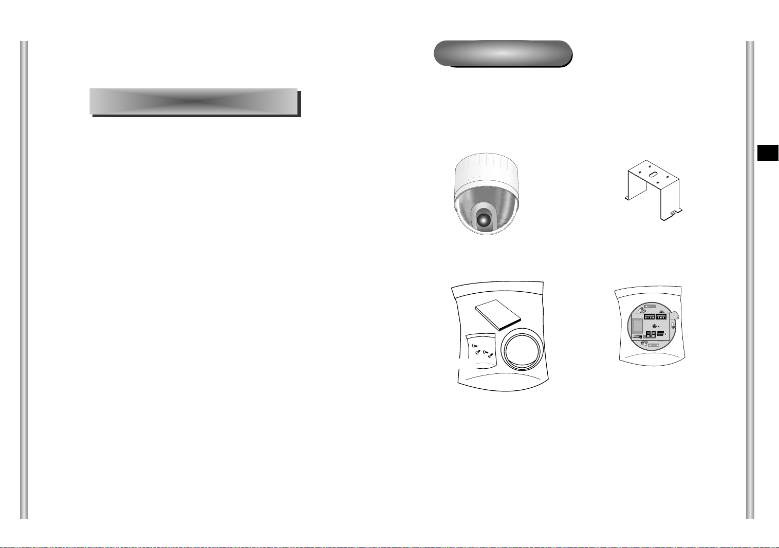
Checking Package Contents
Please check that all components listed below are included in the
package:
Screws
Owner’s
Instructions
Cover Body
SCC-643(P)
Bracket anchor
Camera Holder
E
2-1
2-2

Preparing the Cables
Cable Connection
To install and use the SCC-643(P), the following cables should be
prepared.
Power Adapter Cable
The cable that plugs into the SCC-643(P) power input receptacle has the
rated voltage of 24VAC, 1.5A.
Check the rated voltage before using the cable.
Video Cable
The SCC-643(P)'s cable is a BNC Cable for connecting the video-output
terminal to the video-input terminal of the monitor.
1. First, connect one end of the
BNC video cable connector to
the Video Output Terminal
(VIDEO OUT)
2. Then, connect the other end of
the connector to the Video Input
Terminal of the monitor.
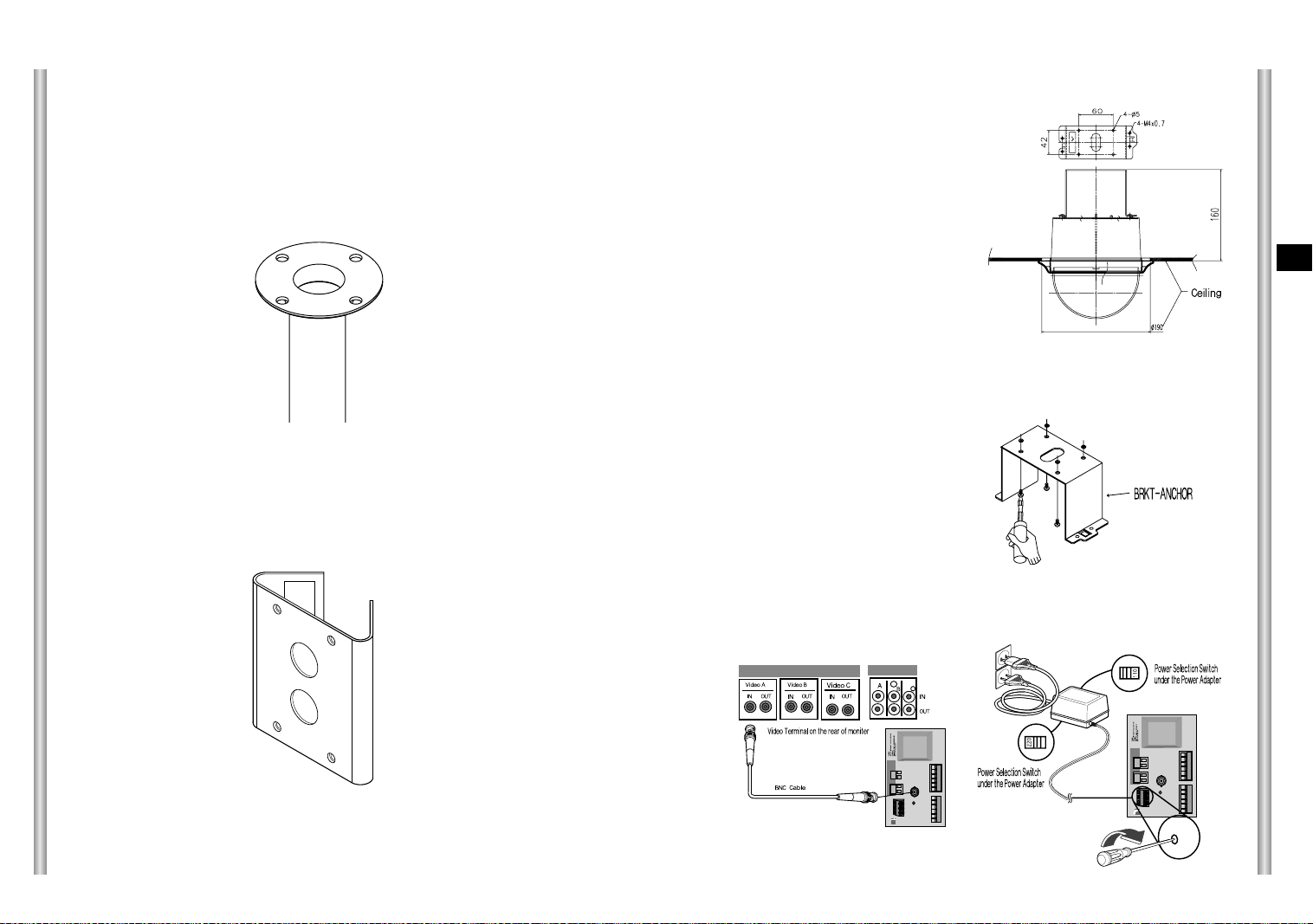
3. Now connect the Power Adapter
Cable. Use a driver to screw
one part of the two lines of
Power Adapter to Power Input
Terminal of the SCC-643(P).
4. Adjust the switch below the Power Adapter to the proper voltage.
Then, connect the Power Adapter's plug to the Power Connector.
E
2-3
5. Connect the Remote Control
Terminal of the SCC-643(P)
and the external Controller.
Controller
Adapter BOARD
2-4

Installing SCC-643(P)
Installation Precautions
1) Make sure that the installation site can sufficiently support a minimum of
four times the net weight of the SCC-643(P) Combi Dome Camera and
other accessories.
2) Install in an area where the space above the ceiling board is over 18 cm
(7 in.) high.
3) Use the supplied screws to fasten the camera to the bracket assembly.
4) Keep persons away from the installation area, as there is a risk of falling
objects.
Also, move valuables to a safe location before installation.
Separately Sold Products for Installation
Depending on the installation site, it may be convenient to use one of the
following products.
1) CEILING MOUNT BRACKET (SBR-100DCM)
This bracket is used for installing
the SMARTDOME CAMERA in the
plenum above the drop ceiling.
3) INDOOR HOUSING (SHG-120)
This housing is used for installing the Combi Dome Camera to an indoor
wall or a ceiling.
E
4) OUTDOOR HOUSING (SHG-220)
This housing is used for installing the Combi Dome Camera to an
outdoor wall or a ceiling.
2) WALL MOUNT ADAPTOR (SADT-100WM)
This adaptor is used for installing the indoor
housing or the outdoor housing for the
Combi Dome Camera on a wall.
2-5
2-6
5) CEILING MOUNT ADAPTOR (SADT-100CM)
This adaptor is used for installing the indoor housing or the outdoor
housing for the Combi Dome Camera to a concrete ceiling.
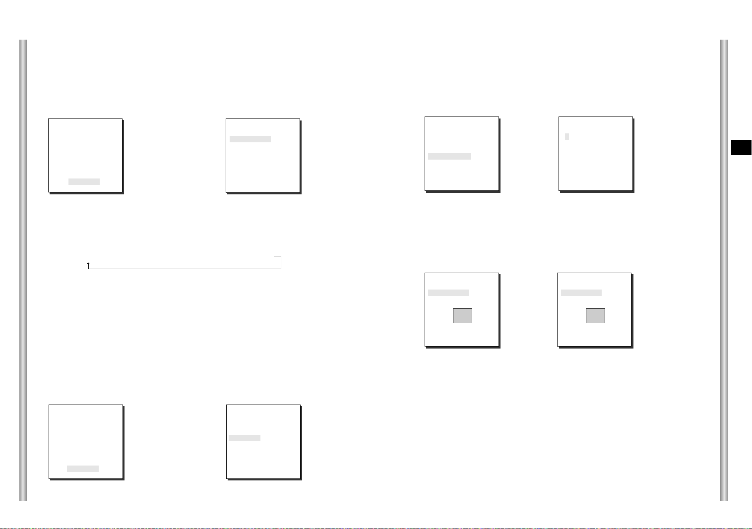
Installing the Camera
1. [Figure 1] Install the structure on the
ceiling.
(Refer to Installation reference
for the Length of the structure)
* Built in by the builder of the structure
E
6) POLE MOUNT ADAPTOR (SADT-100PM)
This adaptor is used for installing the WALL MOUNT ADPATOR
(SBR-100WM) to a pole that is over 7 cm (2.76 in.) in diameter.
[Figure 1]
Length of
ceiling Hole
2. Make a hole in the ceiling where the camera will be installed.
(The hole should be about ø180)
3. [Figure 2] Assemble the
BRKT-ANCHOR on the ceiling
and screw the 4 bolts in.
[Figure 2]
4. [Figure 3,4] Connect the various cables to the CAMERA ADAPTER.
(See page 2-4)
2-7
[Figure 3]
[Figure 4]
2-8

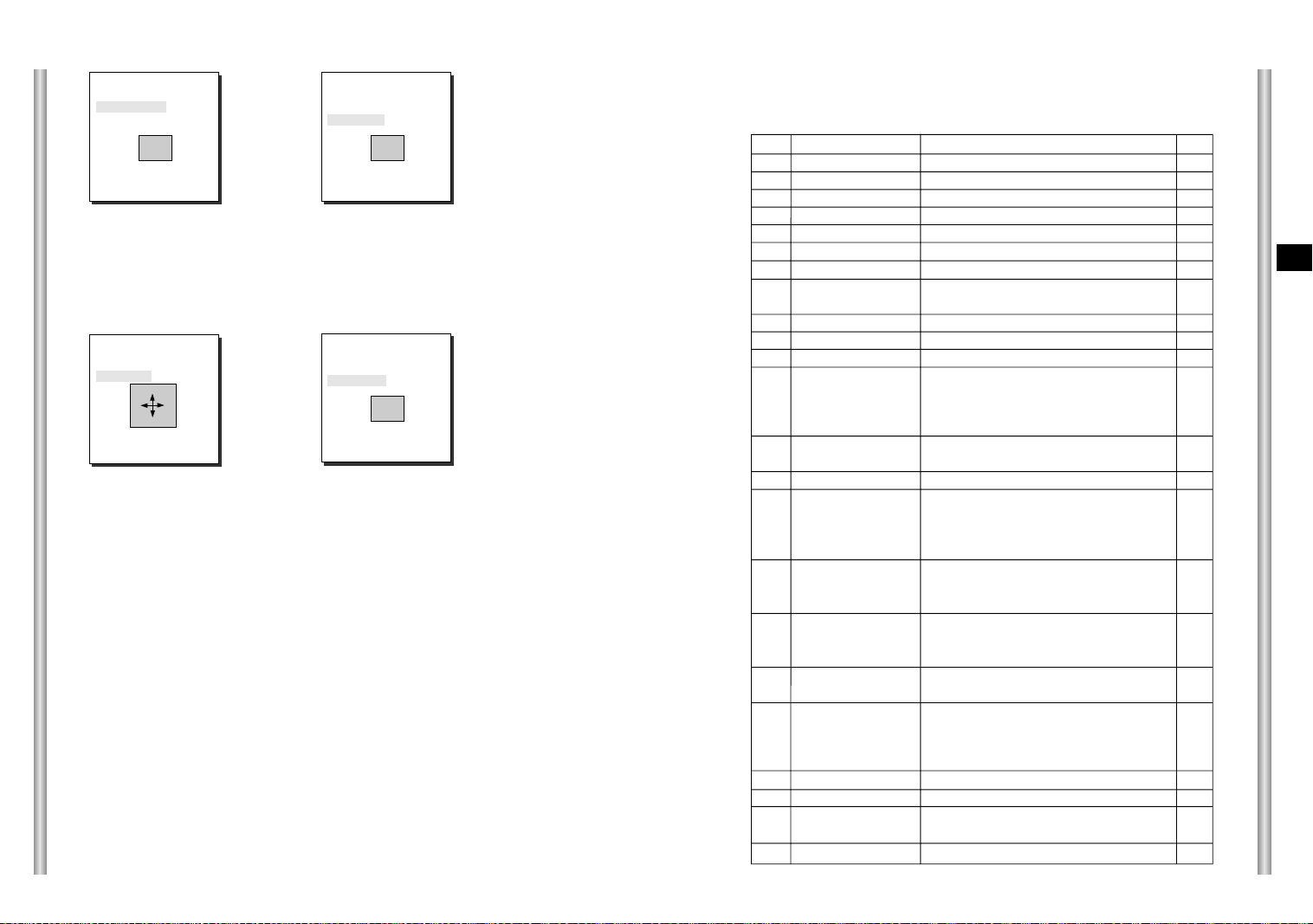
5. [Figure 5] Match the
BRKT-ANCHOR and CAMERA
ADAPTER and use 4screws
(PH M4 x 8) to assemble them.
[Figure 5]
Chapter 3 Setup Menu Overview
CAMERA ADAPTER
6. [Figure 6] Match the 3 holes on
the back of the CAMERA and the
CONNECTOR and turn it left
about 15 degrees.
(Check the sound of LOCKING
and that the LEVER-LOCKING
is in place)
* Use the screws (BH M3 x L8) to
connect the CAMERA and the
ADAPTER so they don't move.
7. [Figure 7] Assemble the
COVER-DOME onto the DOME.
[Figure 6]
15
[Figure 7]
In this chapter, we will look over the Setup Menu of the SCC-643(P),
E
First we'll look over the overall structure of the Setup Menu, and then
we'll look at the functions of each menu.
°
2-9
3-1

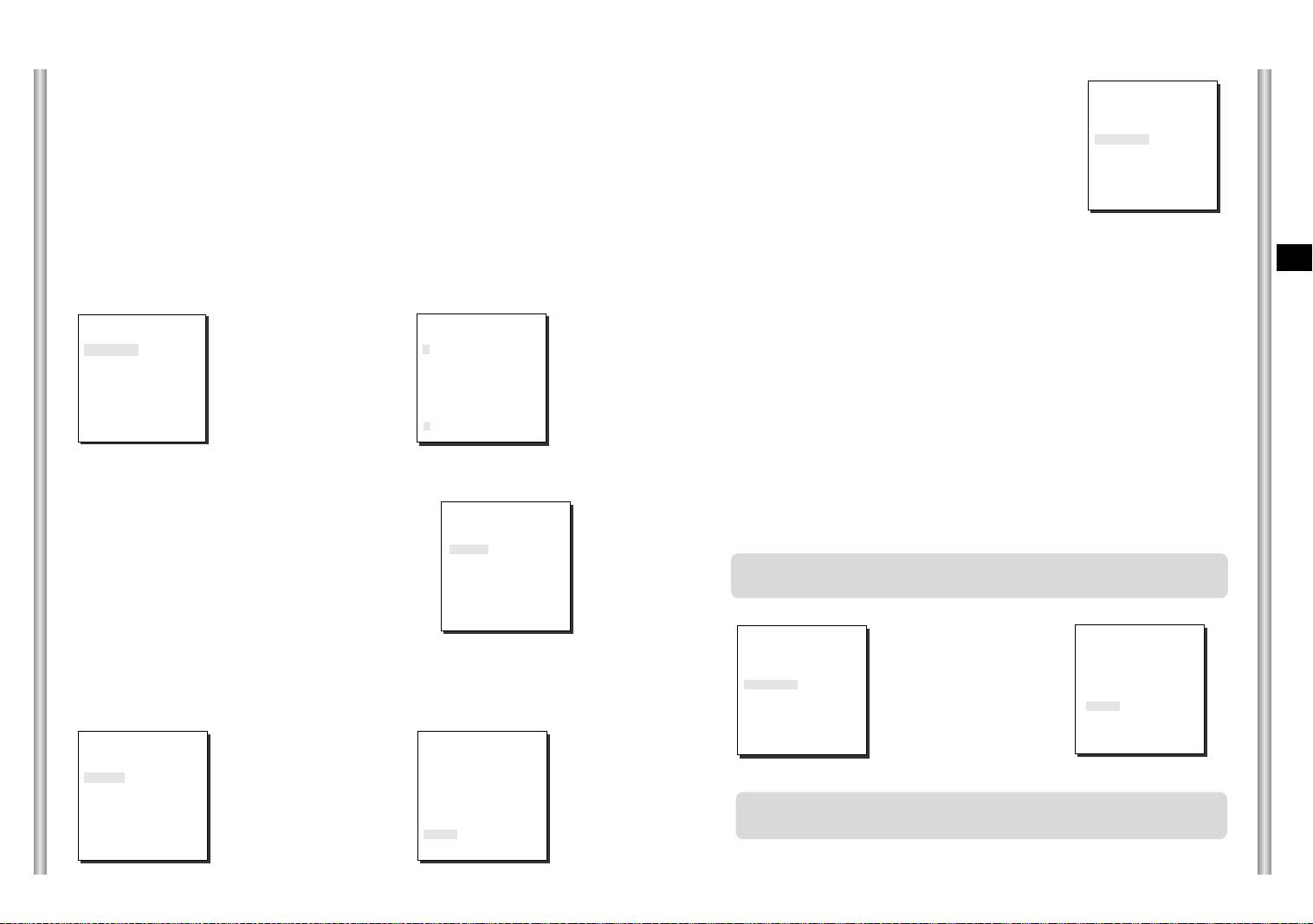
Structure of the Setup Menu
CAMERA CAMERA ID ON.../OFF
V-SYNC INT/LINE...
COLOR/BW COLOR/BW/AUTO...
ZOOM SPEED 1/2/3/4
MOTION DET ON.../OFF
EXIT QUIT/SAVE/PRESET
VIDEO SET IRIS ALC.../MANU...
SHUTTER OFF~1/1OK/AUTO/FIX
AGC OFF/LOW/HIGH
WHITE BAL ATW/AWC/MANU...
SPECIAL ON.../OFF POSI/NEGA
PIP ON.../OFF
MIRROR ON/OFF
H-DTL
V-DTL
RET
AUTO FOCUS AF/MF/ONEAF
D-ZOOM OFF/ X2 ~ X10
EXIT QUIT/SAVE/PRESET
PRESET
AUTO MODE AUTO PAN
PATTERN SET 1/2/3
+ / -
ALARM SET ALARM PRIORITY SET ALARM1 1~4
ALARM2 1~4
ALARM3 1~4
ALARM4 1~4
EXIT QUIT/SAVE
ALARM IN SET ALARM1 NO/NC/OFF
ALARM2 NO/NC/OFF
ALARM3 NO/NC/OFF
ALARM4 NO/NC/OFF
EXIT QUIT/SAVE
ALARM OUT SET ALARM1 1~3
ALARM2 1~3
ALARM3 1~3
ALARM4 1~3
MOTION 1~3
EXIT QUIT/SAVE
ALARM PATTERN SET ALARM1 OFF/1~3/HALF1/HALF2/FULL
ALARM2 OFF/1~3/HALF1/HALF2/FULL
ALARM3 OFF/1~3/HALF1/HALF2/FULL
ALARM4 OFF/1~3/HALF1/HALF2/FULL
MOTION OFF/1~3/HALF1/HALF2/FULL
EXIT QUIT/SAVE
AUX OUT CONTROL OUT1 ON/OFF
OUT2 ON/OFF
OUT3 ON/OFF
EXIT QUIT/SAVE
E
3-2
OTHER SET HOME RETURN OFF/1~60MIN/2~12HOUR
HOME POSITION 0~127
AUTO FLIP ON/OFF
PRIVACY ZONE ...
CAM RESET ...
LANGUAGE ENGLISH
EXIT QUIT/SAVE
The diagram shown above illustrates the overall structure of the Setup
Menu. In this section, a description of the Setup menu features will enable
users of the SCC-643(P) to tailor it to their personal needs.
3-3
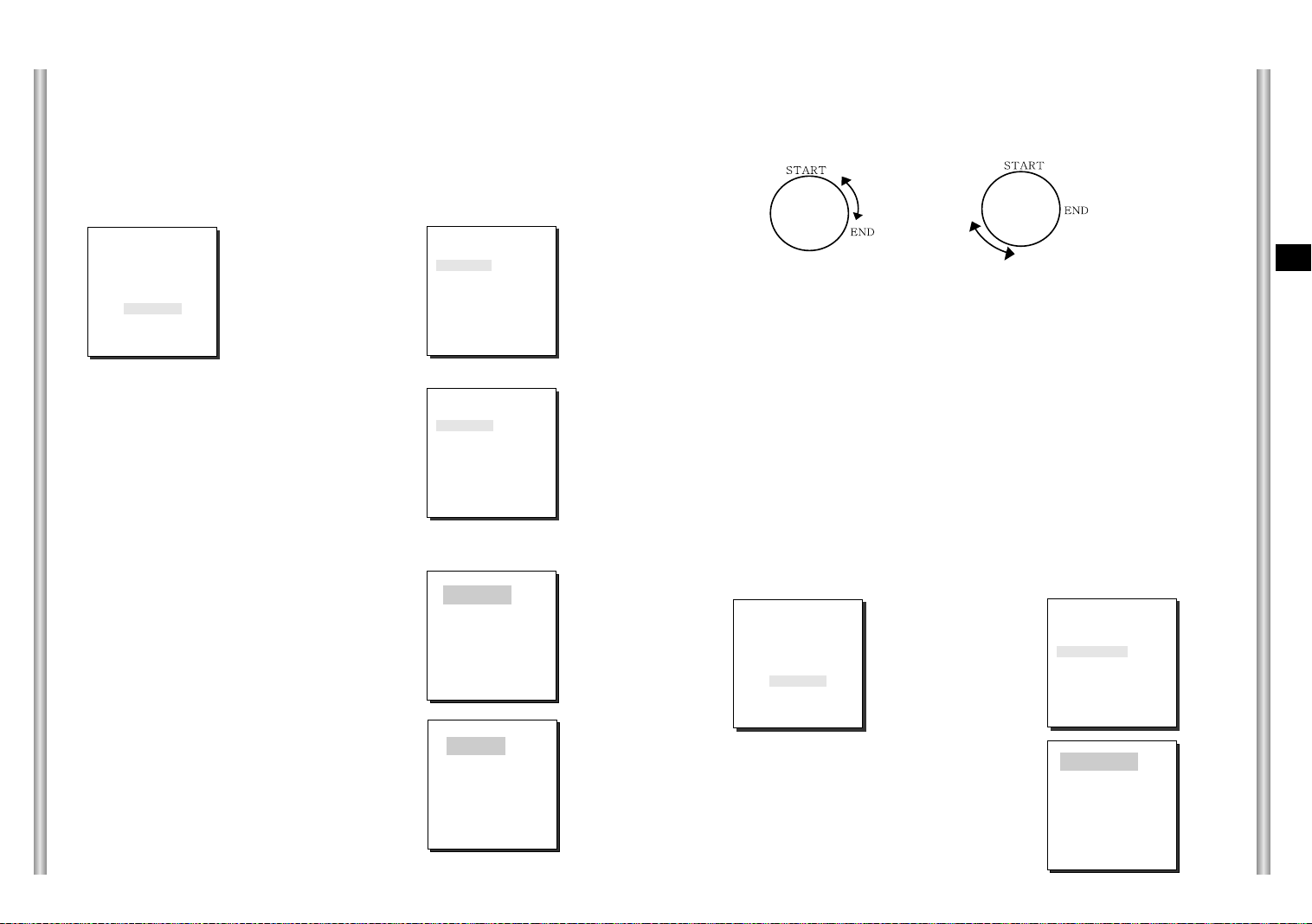
1. CAMERA SET MENU
CAMERA ID
The CAMERA ID menu assigns an ID to the SCC-643(P) to be displayed
on the connected monitor.On the CAMERA SET menu screen, select
CAMERA ID to ON and press [Enter]. You will see the sub screen for
deciding on the ID of the SCC-643(P). The Camera ID can have up to 12
alphanumeric characters, along with several special characters.
The assigned camera ID may be positioned to any desired location on the
screen by using the LOCATION submenu.
(CAMERA SET)
CAMERA ID ON...
V-SYNC INT
COLOR/BW AUTO...
ZOOM SPEED 3
MOTION DET OFF
EXIT QUIT
➜
Press
[Enter]
* " ... " Means there are Sub Menus.
V-SYNC
In the V-SYNC menu, vertical synchronization can
be selected. The vertical synchronization signal
supported by the SCC-643(P) is the INT mode
made by clock inside the SCC-643(P) and LINE
mode adjusting vertical synchronization to the
exterior power frequency.
Select LINE and press [Enter]. You will see the LINE LOCK submenu
where you can adjust the phase of the LINE LOCK.
You can use the PHASE menu of the LINE LOCK submenu to assign as
much PHASE as you want.
(CAMERA SET)
CAMERA ID OFF
V-SYNC LINE...
COLOR/BW AUTO...
ZOOM SPEED 3
MOTION DET OFF
EXIT QUIT
➜
Press
[Enter]
(CAMERA ID)
A B C D E F G H I J K L
M N O PQ R S T U V W X
Y Z 0 1 2 3 4 5 6 7 8 9
: ! - +
✽ ( ) /
SP
ï î
SP
LOCATION...
RET
SCC-643.....
(CAMERA SET)
CAMERA ID OFF
V-SYNC INT
COLOR/BW AUTO...
ZOOM SPEED 3
MOTION DET OFF
EXIT QUIT
(LINE LOCK)
PHASE ( 000) ---RET
I ----
COLOR/BW
In the COLOR/BW menu, you can switch ON or OFF the
IR (infrared) Filter.
In low light conditions, IR Filter is turned OFF to the BW
Mode and the sensitivity to low light increases to that of a
black and white camera. In bright light conditions, the IR
Filter is turned ON to the COLOR Mode, and the screen
changes to normal as the sensitivity decreases.
(CAMERA SET)
CAMERA ID OFF
V-SYNC INT
COLOR/BW AUTO...
ZOOM SPEED 3
MOTION DET OFF
EXIT QUIT
COLOR : The IR Filter is ON and the screen is normal.
BW : The IR Filter is OFF and the screen is black and white.
(Sensitivity to low light is increased to a level comparable to a black and white
camera.)
AUTO : Select to automatically switch between the COLOR mode and BW mode
depending on the amount of light. In low light conditions, the IR Filter is turned OFF
and the sensitivity to low light is increased by switching to the BW mode, but in
bright light conditions, the IR Filter is turned ON and the sensitivity is decreased by
switching to the COLOR mode. If you select AUTO and press the ENTER button, a
screen from which you can set the BURST ON / OFF, BW LEVEL and DWELL
TIME will appear.
- BURST ON : The color burst signal is output together with black and white
composite video signal.
- BURST OFF : The color burst signal is not output.
- LEVEL : You can set the brightness level that changes from COLOR mode to BW
mode in 3 steps : LOW, MEDIUM, and HIGH.
- DWELL TIME : Set the HOLDING time for switching between COLOR and BW
mode depending the changes in the amount of light. You can set the HOLDING
time to 10sec (S), 30sec, 60sec, or 300sec( L).
In AUTO mode, AGC will operates in high speed mode, and you cannot
change it manually, as it is indicated by "---".
(CAMERA SET)
CAMERA ID OFF
V-SYNC INT
COLOR/BW AUTO...
ZOOM SPEED 3
MOTION DET OFF
EXIT QUIT
➜
Press
[Enter]
(BW SETUP)
BURST ON
LEVEL MEDIUM
DWELL TIME S--|----L
RET
Caution : If you use an infrared light source while in AUTO mode, AUTO
switching malfunction and camera AF malfunction may occur.
E
3-4
3-5

ZOOM SPEED
In the ZOOM SPEED menu you can
select the speed of the ZOOM Key
(Tele/Wide).
Use the [Left] or [Right] keys in the
ZOOM SPEED menu to select
the speed.
(CAMERA SET)
CAMERA ID OFF
V-SYNC INT
COLOR/BW AUTO...
ZOOM SPEED 3
MOTION DET OFF
EXIT QUIT
1 : Magnification x 22 takes about 18 seconds. Slowest speed
2 : Magnification x 22 takes about 10 seconds. Low speed
3 : Magnification x 22 takes about 6 seconds. High speed
4 : Magnification x 22 takes about 4 seconds. Fastest speed
If you press [ENTER] once more, you will exit the "AREA" setting menu.Use
the "SENSITIVITY" menu to set the sensitivity of the MOTION Detection.The
Higher it is set, the more sensitive the Motion Detection moves.
➜
Use the [Left, Right, Up, Down] Keys
Press the [5] key to assign an area
or to cancel the area.
E
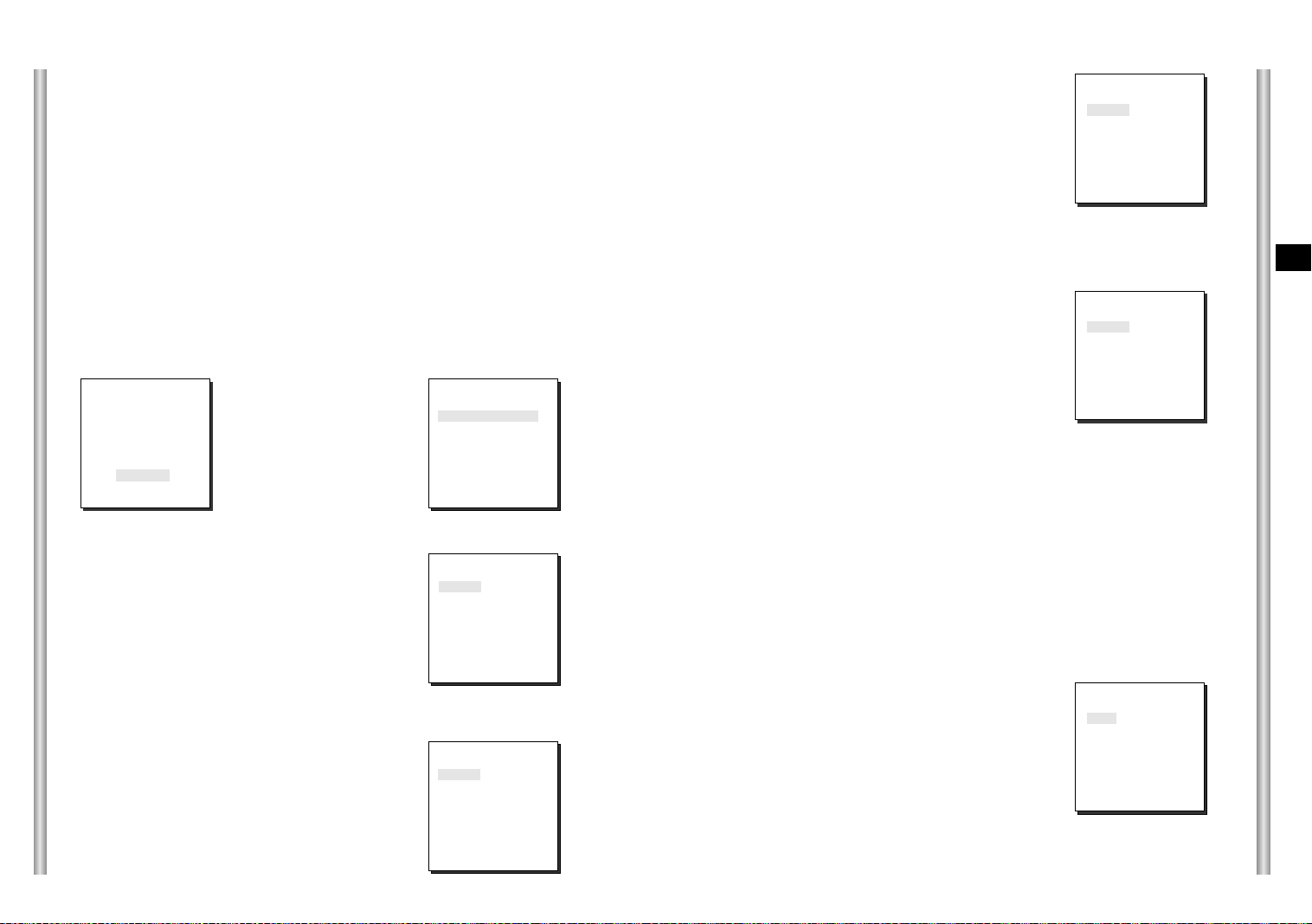
MOTION DET
In MOTION DET, you can set the Motion Detection function, Motion Detection
Sensitivity, and the Area of Motion Detection. If the Motion Detection function
is set, the movement of an intruder can be detected. When motion is detected,
it sets off the Alarm signal of the Controller.
(CAMERA SET)
CAMERA ID OFF
V-SYNC INT
COLOR/BW AUTO...
ZOOM SPEED 3
MOTION DET ON...
EXIT QUIT
➜
Press
[Enter]
If you select ON and press the [ENTER] key, the “MOTION DET” submenu
screen will come up.
The “AREA” menu, from which you can specify screen areas where the Motion
Detection function will be applied, can be set to either PRESET or USER. If
you set the “AREA” menu to PRESET, the Motion Detection function will be
applied to the areas preset as factory defaults.
If you set the AREA menu to USER and press the [ENTER] key, you can
choose from 48 areas where you want to apply the Motion Detection function.
Use the [5] key and [left, right, up, down] keys to move and select the motion
detection area.
Press the [5] key to assign an area or to cancel the area.
(MOTION DET)
AREA PRESET...
SENSITIVITY MEDIUM
RET
*Motion Detection function does not operate while handling slow SHUTTER, PRESET,
SCAN, AUTO MODE(AUTO PAN, PATTERN) or MANUAL KEY (JOYSTICK, ZOOM, FOCUS, IRIS).
EXIT
The EXIT menu is used to quit the CAMERA SET
menu of the SCC-643(P) and return to the MAIN
MENU.
- QUIT: Ignores the changed information and
restores the saved information.
- SAVE: Saves the information of the setting
condition of the menu.
- PRESET: Ignores the changed information and
restores the initial factory defaults of
the menu.
(CAMERA SET)
CAMERA ID OFF
V-SYNC INT
COLOR/BW AUTO...
ZOOM SPEED 3
MOTION DET OFF
EXIT QUIT
2. VIDEO SET MENU
IRIS
The video output level of the monitor can be controlled by the IRIS lens
depending on the level of the incoming light.The video output level can be
set in the ALC menu.The opening and shutting of the Iris lens can be set
manually in the MANU menu.
3-6
3-7

ALC
Choose the ALC of the IRIS item and press [ENTER] and set he submenu to
the Video Output level and BLC will be shown.The Video Output Level can
be set in the level item using the [Left, Right] keys.
MANU
If the IRIS item is set to MANU, the sub screen to open and shut the Iris
manually will be shown. Using the [Left, Right] keys in the LEVEL item
you can set Iris manual setting.
BLC (Submenu of the ALC menu)
With conventional cameras, strong background lighting interferes with the
clarity of objects, making them appear dark. In the SCC-643(P), setting the
BLC (Back Light Compensation), submenu of ALC/MANU menu, will solve
the problem of backlight and give you a clear screen.
Set the BLC menu to ON and the Back Light Compensation function will be
applied to the screen areas of AREA menu.The screen area where Back
Light Compensation should be applied can be set with the PRESET or
USER item.If the AREA menu is set to PRESET, the backlight compensation
function is applied to the factory defaults of the SCC-643(P).
If the AREA menu is set to USER and [ENTER] is pressed, the user can
select the applied area of the backlight compensation function.
(VIDEO SET)
IRIS ALC...
SHUTTER
MOTION
WHITE BAL ATW
SPECIAL OFF
AUTO FOCUS ONEAF
D-ZOOM OFF
EXIT QUIT
AUTO x 4
NORMAL
➜
Press
[Enter]
(ALC)
AREA PRESET...
BLC OFF
LEVEL (0) ----I ---RET
Use the [left, right, up, down] keys to move to the area you want.
Press the [5] key to assign an area or to cancel the area.
Press the [ENTER] key again to exit the “AREA” setup menu.
➜
Use the
[Left, Right, Up, Down] Keys
(VIDEO SET)
IRIS MANU...
SHUTTER
MOTION
WHITE BAL ATW
SPECIAL OFF
AUTO FOCUS ONEAF
D-ZOOM OFF
EXIT QUIT
AUTOx4
NORMAL
➜
Press
[Enter]
(MANUAL)
LEVEL ( 00) ---RET
I ----
SHUTTER
In the SHUTTER menu, the high-speed Electric shutter and AUTO low speed
shutter of the SCC-643(P) and the FIX low speed shutter can be set.
The High speed Electric Shutter supports 7 different speeds from 1/100 to
1/10K of a second. The AUTO low speed shutter and FIX low speed shutter
supports 12 different speeds from 2x to 128x magnifications.
The Low speed shutter is the function that sets the shutter speed to low in
order to clearly see the object filmed in low light. To automatically slow down
the speed of the shutter by sensing the brightness of the light, set to AUTO
low speed shutter, and If the user wants to manually set the speed of low
speed shutter, set it to FIX. The number after the AUTO and FIX are the
number of the fields stored. The larger the number of the fields, the slower the
shutter speed gets, so in a still screen the screen is much clearer.
If the object were in motion it would be blurry.
(VIDEO SET)
IRIS ALC...
SHUTTER
MOTION
WHITE BAL ATW
SPECIAL OFF
AUTO FOCUS ONEAF
D-ZOOM OFF
EXIT QUIT
AUTOx4
NORMAL
E
3-8
3-9

If your press the left/right keys continuously, the speed will appear in the
following order.
Order
OFF ➞ 1/100(1/120) ➞ 1/250 ➞ 1/500 ➞ 1/1000 ➞ 1/2000 ➞
1/4000 ➞ 1/10K ➞ OFF ➞ AUTOX2 ➞ AUTOX4 ➞ AUTOX6 ➞
AUTOX8 ➞ AUTOX12 ➞ AUTOX16 ➞ AUTOX24 ➞ AUTOX32 ➞
AUTOX48 ➞ AUTOX64 ➞ AUTOX96 ➞ AUTOX128 ➞ OFF ➞
FIX X2 ➞ FIX X4 ➞ FIX X6 ➞ FIX X8 ➞ FIX X12 ➞ FIX X16 ➞
FIX X24 ➞ FIX X32 ➞ FIX X48 ➞ FIX X64 ➞ FIX X96 ➞ FIX X128
SLOW
This enhances the resolution of a still image by selecting a low value for
AGC GAIN and a slow speed for SHUTTER SPEED.
(This is used mainly to monitor inanimate objects in dark places.)
NORMAL
This shows the normal picture by selecting a medium value for AGC GAIN
and the normal speed for SHUTTER SPEED.
(This is used mainly to monitor moving objects in dark places.)
E
AGC
In the AGC menu, you can specify whether to automatically control the
GAIN when the obtained video is below a certain level of brightness.
To automatically control the GAIN, set the AGC menu to LOW/HIGH.
Otherwise, set it to OFF.
If the you set the AGC to LOW, the maximum GAIN of the AGC will be set
to low, and if set to HIGH, the maximum GAIN will be set to high.
Under low light conditions, SHUTTER Mode change from AGC to
MOTION (AUTO Mode). In the MOTION, use the [left, right] keys to select
"S.S/SLOW/NORMAL/FAST/F.F".
(VIDEO SET)
IRIS ALC...
SHUTTER OFF
AGC
WHITE BAL ATW
SPECIAL OFF
AUTO FOCUS ONEAF
D-ZOOM OFF
EXIT QUIT
LOW
S.S
This maximally enhances the resolution of a still image by selecting the
lowest value for AGC GAIN and the slowest speed for SHUTTER SPEED.
(This is used mainly to monitor inanimate objects in dark places.)
FAST
This focuses on the moving object by selecting a high value for AGC
GAIN and a high speed for SHUTTER SPEED.
(This is used mainly to monitor objects moving conspicuously in dark
places.)
F.F
This focuses on the fastest moving object by selecting the highest value
for AGC GAIN and the fastest speed for SHUTTER SPEED.
(This is used mainly to monitor fast moving objects in dark places.)
3-10
3-11
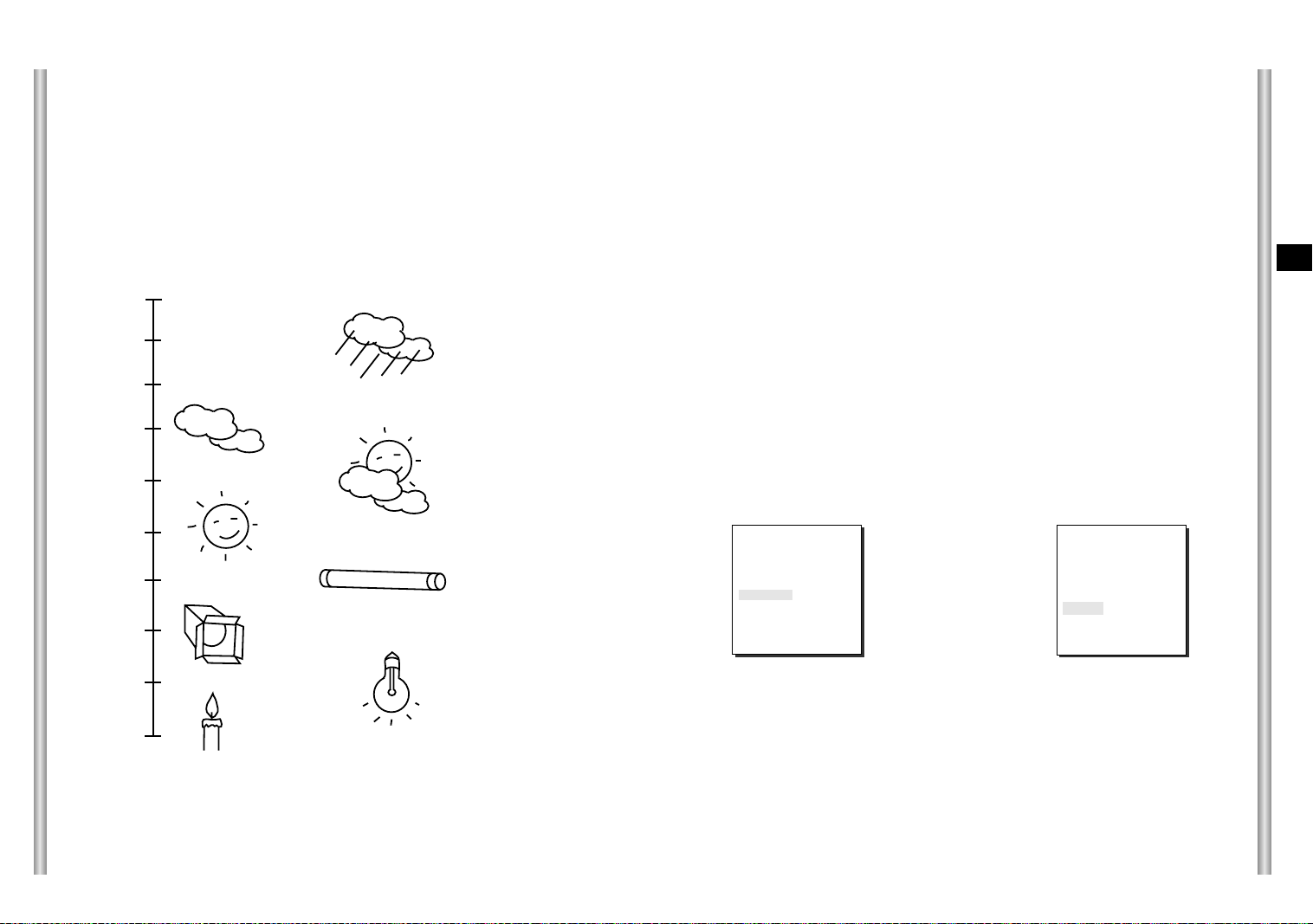
WHITE BAL
Lights are generally denoted as color temperatures and expressed in
°K
°K
°K
°K
) units.
Blue sky
Rainy
Kelvin (
The general light color temperatures are shown below.
10000
9000
8000
WHITE BAL
The WHITE BAL menu insures that white is calibrated normally under any
color temperature condition.
●
When the WHITE BAL menu is set to the ATW mode, the white balance
is automatically specified according to the color temperature.
●
In the case of setting the WHITE BAL menu to AWC mode, pressing
[ENTER] while having a white paper in front of the Camera will
automatically set the white balance in accordance with the color
temperature only one time.
●
If WHITE BAL menu is set to MANUAL mode, the user can set the white
Balance considering the current illumination.
°K
- 3200
: Set color temperature to 3200
- 5600°K: Set color temperature to 5600
- User : Set the appropriate value in the RED and BULE graph.
°K
°K
E
3-12
7000
6000
5000
4000
3000
2000
1000
°K
°K
°K
°K
°K
°K
Cloudy
Partly Cloudy
Sunny
Fluorescent lamp
Halogen lamp
MANU: Select MANU item and press [ENTER], the sub screen where you
can select Manual White Balance will be shown.
Use the left/right keys to select 3200
°K
, 5600°Kor USER mode in the
PRESET menu.
(VIDEO SET)
IRIS ALC...
SHUTTER
MOTION
WHITE BAL MANU...
SPECIAL OFF
AUTO FOCUS ONEAF
D-ZOOM OFF
EXIT QUIT
AUTOx4
NORMAL
➜
Press
[Enter]
(AWB/MANU)
PRESET OFF(USER)..
RED (00) ----I ---BLUE (00) ---RET
I ----
Tungsten lamp
°K
Candlelight
3-13

SPECIAL
In the SPECIAL menu, POSI/NEGA, PIP, Mirror, and vertical and
horizontal detail level can be adjusted.
- POSI/NEGA: Video output signal is outputted normal/reverse.
- PIP(Picture in Picture): When Digital Zoom is activated, the 1/16
minimized screen will be shown.
- MIRROR: Reverse the video output signal
- H-DTL: Adjust Horizontal Detail Level.
- V-DTL: Adjust Vertical Detail Level.
Select ON and press [ENTER], the "SPECIAL" submenu to choose the
special functions will be shown.
horizontally.
AUTO FOCUS
In the AUTO FOCUS MENU, the Focus method can be set to AF, MF, or ONEAF.
- AF: With AUTO FOCUS MODE, you can monitor the screen continuously and it
will focus automatically. While moving the zoom keys, it will automatically
focus so FOCUS key input is not necessary.
- MF: In MANUAL FOCUS MODE the user adjusts the Focus manually.
- ONEAF : The ONEAF Mode performs Auto-focusing only when the SCC-643(P)
stops after moving and when the SCC-643(P) is not moving it is same
as MF mode.
(The ONEAF Mode does not work when zooming out.
❈
When in the MF/ONEAF Mode, press the NEAR and FAR keys on the
Controller (SSC-1000) at the same time to perform AUTO FOCUS.)
Use the left/right keys to select AF, MF or ONEAF in the AUTO FOCUS menu.
E
(VIDEO SET)
IRIS ALC...
SHUTTER
MOTION
WHITE BAL ATW
SPECIAL ON...
AUTO FOCUS ONEAF
D-ZOOM OFF
EXIT QUIT
AUTOx4
NORMAL
➜
Press
[Enter]
(SPECIAL)
POSI/NEGA +
PIP OFF
MIRROR OFF
H-DTL (0) ----I ---V-DTL (0) --- I -----
RET
To choose functions use the left/right keys to select an item.In the PIP
menu, select ON and press [ENTER]. Use the [left, right, up, down]
keys to set the location of the PIP.
❈
The PIP function does not work in the slow-speed Shutter Mode and Privacy
Zone Display Mode, and the Mirror function does not work in the PIP window.
❈
The Mirror function does not work if Privacy Zone is set.
(SPECIAL)
➜
Press
[Enter]
3-14
POSI/NEGA +
PIP ON...
MIRROR OFF
H-DTL (0) ----I ---V-DTL (0) ----I ---RET
PIP Screen
(VIDEO SET)
IRIS ALC...
SHUTTER
MOTION
WHITE BAL ATW
SPECIAL OFF
AUTO FOCUS ONEAF
D-ZOOM OFF
EXIT QUIT
AUTOx4
NORMAL
D-ZOOM
In the D-ZOOM menu, you can choose the Digital Zoom magnification.
You can select a magnification from OFF to 10 times.
When Digital Zoom is selected at 10 times, the camera can show upto
220 times because the Optical Zoom is 22 times.
Use the [left, right] keys to select the magnification in the D-ZOOM menu.
(VIDEO SET)
IRIS ALC...
SHUTTER
MOTION
WHITE BAL ATW
SPECIAL OFF
AUTO FOCUS ONEAF
D-ZOOM OFF
EXIT QUIT
AUTOx4
NORMAL
(VIDEO SET)
IRIS ALC...
SHUTTER
MOTION
WHITE BAL ATW
SPECIAL OFF
AUTO FOCUS ONEAF
D-ZOOM X10
EXIT QUIT
AUTOx4
NORMAL
EXIT
It's the same as the EXIT function of the CAMERA SET menu.
3-15
3. PRESET
This is the menu that user sets the PAN/TILT location, Zoom/Focus, and
screen condition, so the camera can monitor the presetting area on
demand. A total of 128 presets are available.
Among the 128 PRESETS HOME POSITION, PRESET 1: ALARM1,
PRESET 2: ALARM2, PRESET 3: ALARM3, PRESET 4:
ALARM4,PRESET 5: set as special preset corresponding MOTION.
* * MAIN MENU * *
CAMERA...
VIDEO SET...
PRESET...
AUTO MODE...
ALARM SET...
OTHER SET...
➜
Press
[Enter]
➜
Press
[Enter]
PRESET NO.0
POSITION SET...
VIDEO SET OFF
PRESET ID ON...
SCAN ON
DWELL TIME 2 S
(PRESET MAP)
0 H 1 2 3 4
5 6 7 8 9
10 11 12 13 14
15 16 17 18 19
20 21 22 23 24
25 26 27 28 29
î ï
30 31
ID:PRESET 0
RET
❈ " ... " Means there are Sub Menus.
POSITION SET...
From "POSITION SET..." press [ENTER] to get
into the PAN/TILT, FOCUS/ZOOM SET screen
to set the PAN/TILT location and FOCUS/ZOOM
condition then press [ENTER] to return to a
higher menu.
VIDEO SET
This is the screen setting function for each PRESET.
Refer to the explanation under "VIDEO SET menu".
PRESET ID
This is the ID set up function for each PRESET.
It can be set up to 12 characters using the left,
right, up, and down keys.
The ID location can be set in the submenu of
"LOCATION..."
SCAN
This function sets up for movement or no
movement in "SCAN" motion.
When it's PRESET to "ON" it includes SCAN
motion and to "OFF" no movement.
PRESET NO.0
SET PAN/TILT
SET ZOOM/FOCUS
PRESET NO.0 ID
A B C D E F G H I J K L
M N O PQ R S T U V W X
Y Z 0 1 2 3 4 5 6 7 8 9
: ! - + * ( ) /
SP
ï î
SP
LOCATION...
RET
PRESET 0....
PRESET NO.0
POSITION SET...
VIDEO SET... ON...
PRESET ID ON...
SCAN ON
DWELL TIME 2 S
EXIT QUIT
E
3-16
EXIT QUIT
DWELL TIME
This is a function setting for the DWELL TIME of the PRESET location in
"SCAN" motion. It can set DWELL TIME From 1 ~ 60 Sec.
EXIT
"QUIT": Does not save the selected information and returns to a higher
menu.
"SAVE": Do saves the selected information and returns to a higher menu.
"DEL" : Deletes the selected information and restores the DEFAULT.
Then returns to a higher menu.
3-17
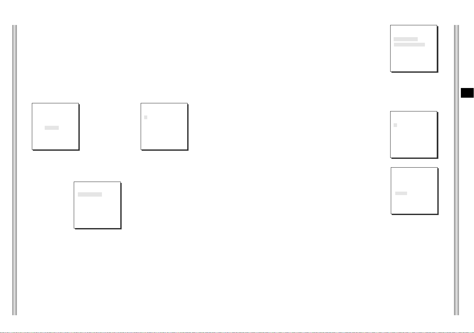
4. AUTO MODE
AUTO PAN and PATTERN functions are in AUTO MODE.
AUTO PAN
After selecting the locations of two points (PAN/TILT) of START and
END, it loops continuously in the set up SPEED.
DIRECTION
This sets up the movement direction of the START to END location
(PAN location standard)
"RIGHT " : "LEFT " :
* * MAIN MENU * *
CAMERA...
VIDEO SET...
PRESET...
AUTO MODE...
ALARM SET...
OTHER SET...
➜
Press
[Enter]
➜
Press
[Enter]
START SET
From "START SET...", get into the START
SET setup screen by pressing [ENTER].
After selecting the locations of PAN/TILT
location, press [ENTER] again to return to
higher menu.
END SET
From "END SET...", get into the END SET
setup screen by pressing [ENTER]. Adjust
PAN/TILT location and press [ENTER] to
return to a higher menu.
(AUTO MODE)
AUTO PAN ...
PATTERN SET 1...
RET
AUTO PAN
START SET ...
END SET ...
DIRECTION RIGHT
ENDLESS ON
SPEED STEP5
DWELL TIME 2 S
EXIT QUIT
SET START!
SET END!
ENDLESS
This is a 360-degree rotation function that stops for the DWELL TIME only in
the START and END positions without running between the START and END
positions. It can be set to "ON" or "OFF".
SPEED
This is a setting function for movement speed setup. It can be set from
STEP1 to STEP64.
DWELL TIME
This is a function for setting up the time to stay in the START to END position.
PATTERN
This is a replay function so that the MANUAL functions such as PAN,
TILT, ZOOM, and FOCUS are played for 30 seconds.
* * MAIN MENU * *
CAMERA...
VIDEO SET...
PRESET...
AUTO MODE...
ALARM SET...
OTHER SET...
➜
Press
[Enter]
(SCAN MODE)
AUTO PAN ...
PATTERN SET 1...
RET
PATTERN1 SET
➜
Press
[Enter]
E
3-18
3-19
PATTERN can be set upto 3. Choose 1, 2, or 3 with the left or right key in the
"PATTERN SET" and press [ENTER] to get into the PATTERN set up screen.
From the moment "PATTERN 1 SET" is gone for 30 seconds, it memorizes the
MANUAL movements and after 30 seconds it will return to a higher menu. If you
want to finish set up before the 30-second ends, press [ENTER].
5. ALARM SET
It consists of 4 ALARM INPUTs and 3 ALARM OUTs.It can sense an
ALARM input from exterior SENSORs and it performs with PRESET or
PATTERN function and outputs the ALARM OUT signals.
It recognizes the ALARM signal input as an ALARM signal when it
continues more than 150ms for a time and each ALARM movement time
is decided depending on it's correspondence to the DWELL TIME of the
PRESET and PATTERN connected.
* * MAIN MENU * *
CAMERA...
VIDEO SET...
PRESET...
AUTO MODE...
ALARM SET...
OTHER SET...
➜
Press
[Enter]
ALARM PRIORITY SET
This sets the priority of the 4 ALARM inputs so
ALARM can work corresponding to the priority.
The priority of the DEFAULT is ALARM1: 1,
ALARM2: 2, ALARM3: 3, ALARM4: 4, MOTION: 5.
If the ALARM is working at the same time and the
priority is the same, it will operate according to the
DEFAULT priority. While the ALARM is working,
it cannot detect MOTION.
ALARM IN SET
This sets the input TYPE to "NO" (Normal Open),
"NC" (Normal Close), or "OFF" depending on the
features of the SENSOR connected.
3-20
( ALARM SET)
ALARM PRIORITY SET..
ALARM IN SET..
ALARM OUT SET..
ALARM PATTERN SET..
AUX OUT CONTROL..
RET
ALARM PRIORITY
ALARM1 1
ALARM2 2
ALARM3 3
ALARM4 4
EXIT QUIT
ALARM IN
ALARM1 NO
ALARM2 NC
ALARM3 NO
ALARM4 NC
EXIT QUIT
ALARM OUT
Each ALARM input corresponds to one of the
3 ALARM OUT.
ALARM OUT
ALARM1 1
ALARM2 2
ALARM3 3
ALARM4 2
MOTION 1
EXIT QUIT
ALARM PATTERN
This sets the operation of PATTERN movements
when inputting ALARM.
When the ALARM is working, it will stay in the
PRESET location corresponding the ALARM for
the DWELL TIME and the ALARM connected to
the PATTERN will continuously operate the
PATTERN movements.
When the ALARM is inputted the correspondence
ALARM PATTERN
ALARM1 OFF
ALARM2 OFF
ALARM3 1
ALARM4 2
MOTION 3
EXIT QUIT
will be as follows: ALARM1 input to PRESET 1,
ALARM 2 input to PRESET 2, ALARM3 input to
PRESET 3, ALARM 4 input to PRESET 4, and
MOTION input to PRESET 5.
The OFF in the Setup Menu does not operate the PATTERN, and it
means 1 ➞ PATTERN1, 2 ➞ PATTERN 2, 3 ➞ PATTERN 3, HALF1 ➞
continuous motion of PATTERN 1 + PATTERN 2, HALF 2 ➞ continuous
motion of PATTERN 2 + PATTERN 3 and FULL ➞ continuous motion of
PATTERN 1+PATTERN2+PATTERN3.
AUX OUT CONTROL
This sets the ALARM OUT motion to continue
or act only when the ALARM is working.
If it is set to OFF the ALARM OUT motion will
operate only when the ALARM is working.
(Active "Low"), and if it's set to ON, the
ALARM OUT will always operate regardless
of the ALARM.
AUX OUT
OUT1 OFF
OUT2 OFF
OUT3 ON
EXIT QUIT
E
3-21
6. OTHER SET
HOME RETURN
When there is no KEY input or other movement for a certain time, the
camera moves to the HOME location automatically. The HOME location
can be assigned from the HOME POSITION menu.
PRIVACY ZONE
Pan/Tilt position and the size of Masking area can be set for up to 8
privacy zones. When shooting the areas where privacy zones are set, the
relevant areas will be concealed from view to protect privacy.
Privacy Zones can be set as follows:
* * MAIN MENU * *
CAMERA...
VIDEO SET...
PRESET...
AUTO MODE...
ALARM SET...
OTHER SET...
➜
Press
[Enter]
(OTHER SET)
HOME RETURN 12HOUR
HOME
POSITION
AUTO FLIP ON
PRIVACY ZONE ...
CAM RESET...
LANGUAGE ENGLISH
EXIT QUIT
0
SET UP TIME FOR HOME RETURN:
OFF: HOME RETURN function cancellation
OFF ➞ 1 MIN ➞ 2 MIN ➞ 3 MIN ~ 60MIN ➞ ~12HOUR
HOME POSITION
You can select the HOME POSITION from the preset positions
numbered between 0 and 127.
AUTO FLIP
When operating the Tilt to the 90° limit using the Joystick, the camera
PAN automatically revolves 180° showing the opposite area of the Tilt area.
It gives the effect of extending the Tilt operating area 180°.
* * MAIN MENU * *
CAMERA...
VIDEO SET...
PRESET...
AUTO MODE...
ALARM SET...
OTHER SET...
➜
[Enter]
KEY
(OTHER SET)
HOME RETURN 12HOUR
HOME POSITION 0
AUTO FLIP ON
PRIVACY ZONE ...
CAM RESET...
LANGUAGE
EXIT QUIT
ENGLISH
(OTHER SET)
HOME RETURN 12HOUR
HOME POSITION
AUTO FLIP ON
PRIVACY ZONE ...
CAM RESET...
EXIT QUIT
0
➜
[Enter]
KEY
(PRIVACY ZONE MAP)
1* 2 3 4
5 6 7 8
RET
➜
[Enter]
KEY
Select PRIVACY ZONE and press the [Enter] key. The PRIVACY ZONE Map
appears and an asterisk "*" is placed next to the numbers set.
Use the [up, down, left, right] keys to select a number you want to set, and then
press the [Enter] key.
PRIVACY ZONE SET 1
SET PAN/TILT ...
SET AREA ...
SET LEVEL 1
EXIT QUIT
➜
[Enter] KEY
Entering the
PAN/TILT
Setup Mode
PRIVACY ZONE SET 1
SET PAN/TILT SET
SET AREA ...
SET LEVEL 1
EXIT QUIT
➜
[Enter] KEY
The PAN/TILT
Setup is
Complete.
When the above screen appears, press the [Enter] key while the SET
PAN/TILT is selected to set the Pan/Tilt position. With OSD showing "SET",
use the Joystick move the Masking area to the center.
After setting the position, press the [Enter] key again to exit the PAN/TILT
position setup.
E
3-22
3-23
PRIVACY ZONE SET 1
SET PAN/TILT ...
SET AREA ...
SET LEVEL 1
EXIT QUIT
➜
[Down] KEY
PRIVACY ZONE SET 1
SET PAN/TILT ...
SET AREA ...
SET LEVEL 1
EXIT QUIT
➜
[Enter] KEY
Entering the
AREA Setup
Mode
To set the area, select "SET AREA" and then press the [Enter] key.
With OSD showing "SET", use the [up, down, left, right] key to set the
AREA size.
PRIVACY ZONE SET 1
SET PAN/TILT ...
SET AREA SET
SET LEVEL 1
EXIT QUIT
➜
[Enter] KEY
The AREA
Setup is
complete.
PRIVACY ZONE SET 1
SET PAN/TILT ...
SET AREA ...
SET LEVEL 1
EXIT QUIT
Select "SET LEVEL" and set the Level of Mask Area.
This Level can be set anywhere from 1 (black) to 8 (white), and the set
level will be applied to all eight areas.
"SAVE" and exit after setting the Level to complete the settings for the
Privacy Zone.
●
Make the area large enough so that the relevant area can be hidden
undermeath it.
CAM RESET
CAM RESET clears all the settings made so far and restores the factory
default settings.
"CAMERA RESET?" message appears when you select CAM RESET.
Select "CANCEL" to return to the menu setup display or select OK to
restore the factory default settings.
●
Be careful when performing a CAM RESET operation, as it deletes all
setup values.
Product specifications
SCC-643
NO
1
2
3
4
5
6
7
8
9
10
11
12
13
14
15
16
17
18
19
20
21
22
23
Items
Product Type
Power Input
Power Consumption
Broadcasting Type
Image Device
Effective Pixels
Scanning Mode
Scanning line Frequency
Synchronization Mode
Resolution
S/N Ratio
Min. Object Illumination
Color Temperature
Signal Output
Lens
PAN Function
TILT Function
REMOTE CONTROL
ALARM
Operation Temperature
Operation Humidity
SIZE
Weight
Zoom lens single body COMBI DOME CAMERA
-
- AC 24 ± 10% (60Hz ± 0.3Hz)
- 18W
- NTSC STANDARD COLOR SYSTEM
- 1/4 inch IT CCD
- 768(H) x 494(V)
- 525 Lines, 2:1 Interlace
- Horizontal : 15, 734 Hz(INT) / 15, 750 Hz(L/L)
Vertical : 59.94 Hz(INT) / 60 Hz(L/L)
- INT/LINE LOCK
- 480 TV LINES
- 52dB (AGC OFF)
- 0.3 Lux (SENS UP X4)
- B/W: 0.4 Lux
- ATW/AWC/MANUAL MODE
(3200°K, 5600°K, R/B GAIN Court)
COMPOSITE VIDEO OUT : 1.0 Vp-p 75 ohms/BNC
-
- one body; 22x Zoom lens
- Focal length : 3.6 to 79.2 mm
- Aperture : F1.6(Wide), F3.8(Tele)
- Auto Focus
- PAN range : 360° Endless
- Preset Pan Speed : 240° /sec, maximum
- Manual Pan Speed : 0.8° ~ 90° /sec (64Step)
- TILT range : 0° ~ 90°
- Preset Tilt Speed : 150° /sec, maximum
- Manual Tilt Speed : 0.8° ~ 45° /sec (64Step)
- Tele/Wide(ZOOM), Near/Far(FOCUS),
Iris Open/Close, Pan/Tilt
- Alarm Inputs : 4 IN(5mA Sink)
- Alarm Outputs : 3 OUT (Open collector : 2
DC24V 40mA Max, Relay : 1, NO, NC, COM
2A 30VDC, 0.5A 125VAC Max)
- 14°F ~ 122°F
- ~90%
- DOME : 147 (ø),
Outline : 159.5(ø) x 176(H)(Adapter:23.5(H)mm)
- 2Kg
Contents
E
(0.01 Lux)
(0.003 Lux)
3-24
3-25

Product specifications
SCC-643P
NO
1
2
3
4
5
6
7
8
Scanning line Frequency
9
Synchronization Mode
10
11
Min. Object Illumination
12
13
14
15
16
17
18
REMOTE CONTROL
19
Operation Temperature
20
21
22
23
Items
Product Type
Power Input
Power Consumption
Broadcasting Type
Image Device
Effective Pixels
Scanning Mode
Resolution
S/N Ratio
Color Temperature
Signal Output
Lens
PAN Function
TILT Function
ALARM
Operation Humidity
SIZE
Weight
Contents
Zoom lens single body COMBI DOME CAMERA
-
- AC 24 ± 10% (50Hz ± 0.3Hz)
- 18W
- PAL STANDARD COLOR SYSTEM
- 1/4 inch IT CCD
- 752(H) x 582(V)
- 625 Lines, 2:1 Interlace
- Horizontal : 15, 625 Hz(INT) / 15, 625 Hz(L/L)
Vertical : 50 Hz(INT) / 50 Hz(L/L)
- INT/LINE LOCK
- 480 TV LINES
- 52dB (AGC OFF)
- 0.3 Lux (SENS UP X4)
(0.01 Lux)
- B/W: 0.4 Lux
(0.003 Lux)
- ATW/AWC/MANUAL MODE
(3200°K, 5600°K, R/B GAIN Court)
COMPOSITE VIDEO OUT : 1.0 Vp-p 75 ohms/BNC
-
- one body; 22x Zoom lens
- Focal length : 3.6 to 79.2 mm
- Aperture : F1.6(Wide), F3.8(Tele)
- Auto Focus
- PAN range : 360° Endless
- Preset Pan Speed : 240° /sec, maximum
- Manual Pan Speed : 0.8° ~ 90° /sec (64Step)
- TILT range : 0° ~ 90°
- Preset Tilt Speed : 150° /sec, maximum
- Manual Tilt Speed : 0.8° ~ 45° /sec (64Step)
- Tele/Wide(ZOOM), Near/Far(FOCUS),
Iris Open/Close, Pan/Tilt
- Alarm Inputs : 4 IN(5mA Sink)
- Alarm Outputs : 3 OUT (Open collector : 2
DC24V 40mA Max, Relay : 1, NO, NC, COM
2A 30VDC, 0.5A 125VAC Max)
- 14°F ~ 122°F
- ~90%
- DOME : 147 (ø),
Outline : 159.5(ø) x 176(H)(Adapter:23.5(H)mm)
- 2Kg
Cautions
• The copyright of the manual belongs to Samsung Electronics Co.,
Ltd.
•
Without the permission of Samsung Electronics it cannot be
reproduced
method.
•
This manual will be modified according to product enhancements.
electronically, mechanically, audibly, or by any other
E
3-26
3-27

Combi Dome Camera
SCC-643(P)
Benutzerhandbuch
D

Sicherheitshinweise
Ziel dieser Informationen ist es, den ordnungsgemäßen Gebrauch dieses
Geräts sicherzustellen und dadurch Gefahren oder Sachbeschädigungen zu
vermeiden. Bitte befolgen Sie alle Anweisungen.
* Die Sicherheitshinweise sind mit “Warnung” und “Achtung”
gekennzeichnet, wie nachfolgend angegeben:
Warnung: Die Nichtbeachtung eines Warnhinweises kann zum Tode oder
Achtung: Die Nichtbeachtung eines mit Achtung gekennzeichneten
Die mit Warnung gekennzeichneten
Informationen weisen auf eine mögliche
Gefahr hin, die zum Tode oder zu
schweren Verletzungen führen kann.
zu schweren Verletzungen führen.
Hinweises kann zu Verletzungen und Sachschaden führen.
Die mit Achtung gekennzeichneten
Informationen weisen auf eine mögliche
Gefahr hin, die zu Verletzungen oder
Sachschaden führen kann.
Warnung
6. Platzieren Sie keine leitfähigen Gegenstände (wie z. B. Schraubenzieher,
Münzen und metallene Objekte) oder mit Wasser gefüllte Behälter auf der
Kamera. (Dies kann zur Verletzung von Personen durch Feuer, Stromschlag
oder herunterfallende Gegenstände führen.)
7. Die Kamera darf nicht an einem feuchten, staubigen oder rußigen Ort installiert
werden. (Andernfalls besteht die Gefahr eines Brandes oder Stromschlags.)
8. Bei ungewöhnlicher Geruchs- oder Rauchentwicklung muss der Betrieb des
Geräts sofort beendet werden. Ziehen Sie unverzüglich den Netzstecker und
setzen Sie sich mit einem Kundendienstzentrum in Verbindung.
(Die Weiterbenutzung des Geräts kann zu einem Brand oder elektrischen
Schlag führen.)
9. Wenn das Gerät nicht einwandfrei funktioniert, wenden Sie sich bitte an die
Verkaufsstelle, in der Sie das Gerät erworben haben, oder an das nächste
Kundendienstzentrum. Das Gerät darf niemals und in keiner Weise selbst
zerlegt oder modifiziert werden. (SAMSUNG übernimmt keine Haftung für
Probleme, die durch unbefugte Abänderungen oder einen Reparaturversuch
herbeigeführt sind.)
10. Wasser darf beim Reinigen niemals direkt auf die Geräteteile gelangen.
(Andernfalls besteht die Gefahr eines Brandes oder Stromschlags.)
Die Oberfläche kann mit einem trockenen Tuch abgewischt werden.
Verwenden Sie keine Reinigungsmittel oder chemischen Reiniger, da sich
durch solche Mittel die Farbe ablösen und der Oberflächenüberzug beschädigt
werden kann.
D
1. Achten Sie darauf, dass Sie nur den mitgelieferten Adapter verwenden.
(Die Verwendung eines anderen Adapters als des mitgelieferten kann Feuer,
einen Stromschlag oder die Beschädigung des Geräts verursachen.)
2. Beim Anschließen der Netz- und Signalkabel müssen zuvor die externen
Anschlussbuchsen überprüft werden. Schließen Sie die Alarmsignalkabeladern
an die Alarmanschlüsse, den Netzadapter an die Netzsteckdose und den
Gleichstromadapter an den Gleichstromeingang an, und achten Sie dabei auf
die richtige Polarität.
(Ein falscher Anschluss an das Stromnetz kann zu Feuer, einem Stromschlag
oder zur Beschädigung des Geräts führen.)
3. Schließen Sie nicht mehrere Kameras an einen Adapter an.
(Wird die Kapazität überschritten, kann es zu einer anormalen
Wärmeentwicklung oder Feuer kommen.)
(Fällt die Kamera herunter, kann es zur Verletzung von Personen kommen.)
4. Stecken Sie das Netzkabel fest in die Steckdose ein.
(Ein loser Anschluss kann einen Brand verursachen.)
5. Bei der Wand- oder Deckeninstallation ist darauf zu achten, dass die Kamera
sicher und fest angebracht wird. (Fällt die Kamera herunter, kann es zur
Verletzung von Personen kommen.)
Achtung
1. Lassen Sie keine Gegenstände auf das Gerät fallen, und schützen Sie es vor
starken Stößen. Setzen Sie die Kamera keinen starken Vibrationen oder
magnetischen Störfeldern aus.
2. Die Kamera darf nicht an Orten mit hohen bzw. tiefen Temperaturen
(über 50 °C und unter -10 °C) oder hoher Luftfeuchtigkeit installiert werden.
(Andernfalls besteht die Gefahr eines Brandes oder Stromschlags.)
3. Installieren Sie das Gerät nicht in der Nähe von Wärmequellen, wie z. B.
einem Heizgerät oder Heizkörper, und an Orten, an denen es direktem
Sonnenlicht ausgesetzt ist. (Hier besteht Feuergefahr.)
4. Wenn Sie die bereits installierte Kamera an einen anderen Ort verlegen
wollen, achten Sie darauf, die Kamera auszuschalten, bevor Sie sie
abnehmen oder neu installieren.
5. Die Installation sollte an einer gut belüfteten Stelle erfolgen.
6. Ziehen Sie bei einem Gewitter den Netzstecker. (Wird dies nicht beachtet,
kann ein Brand verursacht oder das Gerät beschädigt werden.)
 Loading...