

Page 1
High Resolution Camera
User Manual
SCB-2005
Page 2

gh Resolution Camera
Hi
User Manual
Copy
right
Samsung Techwin Co., Ltd. All rights reserved.©
de mar k
Tra
The name of t his product is the re gistered tradem ark of Samsung Techwin C o., Ltd.
Other tr ademarks mentio ned in this manual are t he registered tra demark of their res pective company.
Restriction
msung Techwin C o., Ltd shall reser ve the copyright of t his document. Und er no circumstanc es, this document
Sa
shall be rep roduced, distr ibuted or changed, p artially or who lly, without formal a uthorization o f Samsung Techwin.
aimer
Discl
Samsung Tech win makes the best to v erify the integr ity and correc tness of the conte nts in this documen t, but
no formal gu arantee shall be pr ovided. Use of this d ocument and the sub sequent results s hall be entirely on
the user’s ow n responsibilit y. Samsung Techwin rese rves the right to ch ange the content s of this document
without p rior notice.
Warra nty
If the pro duct does not oper ate properly in no rmal conditions , please let us know. S amsung Techwin will reso lve
the probl em for free of charge. T he warranty pe riod is 3 years. How ever, the followings are e xcluded:
•
If the sys tem behaves abnorm ally because you ru n a program irrelev ant to the system ope ration.
•
Deterio rated perform ance or natural wor n-out in proces s of time
Design and specifications are subject to change without prior notice.
i
he registe red logo of Samsung Tec hwin Co., Ltd.
s t
Page 3

Before operating the camera, confirm the camera model and correct input power voltage.
To help you understand this manual thoroughly, we’ll introduce our model description.
■ SCB-2005 SERIES
• NTSC MODEL
SCB-2005N / 2005ND
• PAL MODEL
SCB-2005P / 2005PD
• POWER SOURCE
SCB-2005N, SCB-2005P : DC12V,AC24V
SCB-2005ND, SCB-2005PD : DC12V
Page 4
Safety information
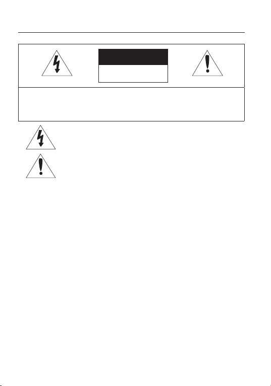
CAUTION
R
ISK OF ELECTRIC SHOCK.
DO NOT OPEN
REDUCE THE RISK OF ELECTRIC SHOCK, DO NOT REMOVE
CAUTION:
WARNING
T
•
o prevent damage which may result in fire or electric shock hazard, do not expose this
appliance to rain or moisture.
To prevent injury, this apparatus must be securely attached to the floor/wall in accordance
•
with the installation instructions.
W
ARNING
sure to use only the standard adapter that is specified in the specification sheet.
Be
1.
Using any other adapter could cause fire, electrical shock, or damage to the product.
Incorrectly connecting the power supply or replacing battery may cause explosion, fire,
2.
electric shock, or damage to the product.
Do not connect multiple cameras to a single adapter. Exceeding the capacity may cause
3.
abnormal heat generation or fire.
Securely plug the power cord into the power receptacle. insecure connection may cause
4.
fire.
When installing the camera, fasten it securely and firmly. The fall of camera may cause
5.
personal injury.
TO
COVER (OR BACK) NO USER SERVICEABLE PARTS INSIDE. REFER
SERVICING TO QUALIFIED SERVICE PERSONNEL.
Thi
s symbol indicates that dangerous voltage consisting a risk of electric
shock is present within this unit.
i
s exclamation point symbol is intended to alert the user to the
Th
presence of important operating and maintenance (servicing) instructions
in the literature accompanying the appliance.
4_ Safety information
Page 5

Do
6.
not place conductive objects (e.g. screwdrivers, coins, metal parts, etc.) or containers
filled with water on top of the camera. doing so may cause personal injury due to fire,
electric shock, or falling objects.
Do not install the unit in humid, dusty, or sooty locations. doing so may cause fi
7.
electric shock.
8.
If any unusual smells or smoke come from the unit, stop using the product. in such case,
re or
immediately disconnect the power source and contact the service center. continued use in
such a condition may cause fire or electric shock.
9.
If this product fails to operate normally, contact the nearest service center. never
disassemble or modify this product in any way. (samsung is not liable for problems caused
by unauthorized modifications or attempted repair.)
10.
When cleaning, do not spray water directly onto parts of the product. doing so may cause
fire or electric shock.
CAUTION
1.
not drop objects on the product or apply strong shock to it. Keep away from a location
Do
subject to excessive vibrationor magnetic interference.
2.
Do not install in a location subject to high temperature (over 55°C), low temperature (below
-10°C), or high humidity. Doing so may cause fire or electric shock.
3.
If you want to relocate the already installed product, be sure to turn off the power and then
move or reinstall it.
4.
Remove the power plug from the outlet when then there is a lightning. Neglecting to do so
may cause fire or damage to the product.
5.
Keep out of direct sunlight and heat radiation sources. It may cause fire.
6.
Install it in a place with good ventilation.
7.
Avoid aiming the camera directly towards extremely bright objects such as sun, as this
may damage the CCD image sensor.
8.
Apparatus shall not be exposed to dripping or splashing and no objects filled with liquids,
such as vases, shall be placed on the apparatus.
9.
The Mains plug is used as a disconnect device and shall stay readily operable at any time.
10.
Do not expose the camera to radioactivity. Radioactivity exposure may damage the CCD.
●
SAFETY INFORMATION
English_5
Page 6
Safety information
FCC STA
TEMENT
Th
is device complies with part 15 of the FCC Rules. Operation is subject to the following two
conditions :
This device may not cause harmful interference, and
1)
This device must accept any interference received including interference that may cause
2)
undesired operation.
CAUTION
is equipment has been tested and found to comply with the limits for a Class A digital
Th
device, pursuant to part 15 of FCC Rules. These limits are designed to provide reasonable
protection against harmful interference when the equipment is operated in a commercial
environment.
This equipment generates, uses, and can radiate radio frequency energy and, if not
installed and used in accordance with the instruction manual, may cause harmful
interference to radio communications. Operation of this equipment in a residential area is
likely to cause harmful interference in which case the user will be required to correct the
interference at his own expense.
IC
Compliance Notice
This Class A digital apparatus meets all requirements of the Canadian
Interference.-Causing Equipment Regulations of ICES-003.
Correct Disposal of This Product
(Applicable in the European Union and other European countries with separate collection systems)
This marking on the product, accessories or literature indicates that the product and its electronic accessories
(e.g. charger, headset, USB cable) should not be disposed of with other household waste at the end of their
working life. To prevent possible harm to the environment or human health from uncontrolled waste disposal,
please separate these items from other types of waste and recycle them responsibly to promote the sustainable
reuse of material resources.
Household users should contact either the retailer where they purchased this product, or their local government
office, for details of where and how they can take these items for environmentally safe recycling.
Business users should contact their supplier and check the terms and conditions of the purchase contract.
This product and its electronic accessories should not be mixed with other commercial wastes for disposal.
Correct disposal of batteries in this product
(Applicable in the European Union and other European countries with separate battery return systems.)
This marking on the battery, manual or packaging indicates that the batteries in this product should not be
disposed of with other household waste at the end of their working life. Where marked, the chemical symbols
Hg, Cd or Pb indicate that the battery contains mercury, cadmium or lead above the reference levels in EC
Directive 2006/66. If batteries are not properly disposed of, these substances can cause harm to human health
or the environment.
To protect natural resources and to promote material reuse, please separate batteries from other types of waste
and recycle them through your local, free battery return system.
6_ Safety information
(Waste Electrical & Electronic Equipment)
Page 7
Read these instructions.
1.
Keep these instructions.
2.
Heed all warnings.
3.
Follow all instructions.
4.
Do not use this apparatus near water.
5.
Clean only with dry cloth.
6.
Do not block any ventilation openings. Install in accordance with the manufacturer’s
7.
instructions.
Do not install near any heat sources such as radiators, heat registers, or other apparatus
8.
(including amplifi ers) that produce heat.
Do not defeat the safety purpose of the polarized or grounding-type plug. A polarized plug
9.
has two blades with one wider than the other. A grounding type plug has two blades and
a third grounding prong. The wide blade or the third prong is provided for your safety. If
the provided plug does not fi t into your outlet, consult an electrician for replacement of the
obsolete outlet.
Protect the power cord from being walked on or pinched particularly at plugs,
10.
convenience receptacles, and the point where they exit from the apparatus.
Only use attachments/accessories specifi ed by the manufacturer.
11.
Use only with cart, stand, tripod, bracket, or table specifi ed by the
12.
manufacturer, or sold with the apparatus.
Unplug this apparatus when a card is used. Use caution when moving the
13.
cart/ apparatus combination to avoid injury from tip-over.
Refer all servicing to qualifi ed service personnel. Servicing is required when the apparatus
14.
has been damaged in any way, such as powersupply cord or plug is damaged, liquid has
been spilled or objects have fallen into the apparatus, the apparatus has been exposed to
rain or moisture, does not operate normally, or has been dropped.
●
SAFETY INFORMATION
Apparatus shall not be exposed to dripping or splashing and no objects
fi lled with liquids, such as vases, shall be placed on the apparatus
Samsung Techwin cares for the environment at all product manufacturing
stages to preserve the environment, and is taking a number of steps to provide
customers with more environment-friendly products.The Eco mark represents
Samsung Techwin’s will to create environment-friendly products, and indicates
that the product satisfies the EU RoHS Directive.
English_7
Page 8

Contents
INTRODUCTION
TROUBLESHOOTING
SPECIFICATIONS
9
CONNECTION
1
3
SETUP
18
29
30
9
Features
10
What’s included
11
Component names and Functions
13
Lens
Connecting to Monitor
15
Connecting to Power
15
16
Using coaxial communications
18
Menu Confi
18
Menu Setup
29
Troubleshooting
Specifi
3
32
gration
cations
Dimension
8_ Contents
Page 9

Introduction
FEATURES
High Resolution
By adopting a diagonal 6mm (1/3”) 520,000 pixel (NTSC), 610,000 pixel (PAL)
SONY CCD, the camera pr
of 700TV lines(ER mode).
Excellent Sensitivity
The built-in high sensitivity COLOR CCD produces a clear image.
0.1Lux ([email protected]) / 0.0002Lux ([email protected], SENS-UP x512)
Samsung Super Noise Reduction) Function
(
6615
The high-performance W6 DSP chip ef
afterimage to provide clear images even in dark environments.
Day & Night
This camera has a function that automatically selects the mode that is appropriate
for daytime or night-time conditions.
conditions to provide
to enhance the definition of the image.
Defog
The camera is able to recognize the concer
ect image of the bad weather such as fog, rain, mist, fumes, etc to make it clear.
defog, corr
SSDR (Samsung Super Dynamic Range)
For images with high contrast between bright and dark areas fr
such as backlighting, this camera selectively illuminates darker areas while
conditions
retaining the
Miscellaneous Functions
HLC(High Light Compensation),SENS-UP, H-REVERSE , SHARPNESS, PRIV
and MOTION DET. functions
Communication
Coaxial communication methods are supported.
- Protocol : Pelco Coaxitron
Osd
The camera control is convenient by using 17 different foreign language O.S.D.
- NTSC : English, Japanese, Spanish, French, Portuguese, Korean
- PAL :
same light level for brighter areas to even out the overall brightness.
English, French, German, Spanish, Italian, Chinese, Russian, Polish,
Czech, Romanian, Serbian, Swedish, Danish, Turkish, Portuguese
oduces clear picture quality with a horizontal resolution
fectively removes low-light gain noise and
The COLOR mode operates in daytime
optimum colors, and B/W mode operates in night-time conditions
ntration of fog in the image, and automatically
om difficult lighting
are provided.
English_9
ACY
●
INTRODUCTION
Page 10

Introduction
WHAT’S INCLUDED
Check if the following items are included in the product package.
Camera
High Resolution
Quick Manual
SCB-2005
Quick ManualCamera
C Mount Adapter
10_ Introduction
Page 11
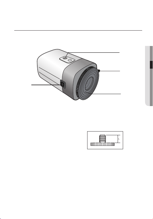
COMPONENT NAMES AND FUNCTIONS
Front
➍
❶
Tripod Mounting Bracket Screw Hole :
Tripod Mounting Bracket .
T
he screw size : use this screw to fix the mounting
1
/4” -20UNC(20THREAD)
L : 4.5mm±0.2mm (ISO Standard), or
0.197” (ASA Standard)
Used to fix the
bracket .
●
❶
➌
➋
INTRODUCTION
➋
Mount Lens Adapter
➌
Back Focus Control Lever :
➍
Auto Iris Lens Connector :
T
ripod is not supplied with the camera. Please check the installed documentation of
tripod for the installation of cameras.
:
Install this adapter to use a
Adjust focus by this Back Focus Control Lever.
Used to connect Auto Iris Lens plug.
CS-Mount Lens.
English_11
Page 12
Introduction
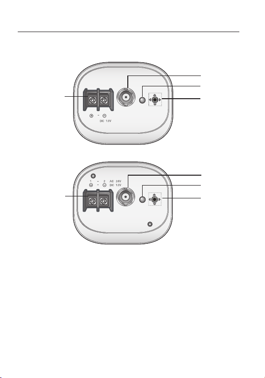
Back
➎
➎
POWER
VIDEO
<DC12V (SCB-2005D)>
POWER
CLASS 2 ONLY
<AC24V/DC12V (SCB-2005)>
VIDEO
➏
➐
➑
➏
➐
➑
➎
Power input terminal : Connects to the power a
➏
Video OUT Terminal :
the monitor.
➐
Power LED : This lamp is lit when the camera is receiving po
➑
Function Setup Button
directions to confirm ststus or after changing a selected item.
Sends video signal and connects to the video input terminal of
:
Display the menu on the screen and move the cursor to four
12_ Introduction
ppropriate to each model.
wer normally
.
Page 13
Connection
Lens
The lens is not supplied with this camera. Purchase a lens suitable for your environment.
This camera accepts the auto iris lens and both C and CS-mount
o use the functions of this camera effectively it is recommended that a DC type Auto Iris
T
lens is used.
Keep the lens surface clean, if it becomes contaminated with dirt or fingerprints the
picture quality suffers.
lens.
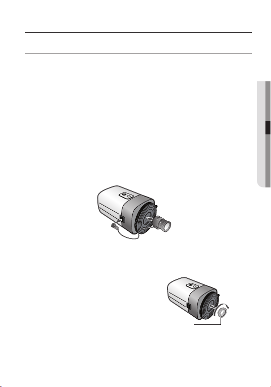
When Using Auto Iris Lens
1.
Remove the protective cover from the front of the camera, and fasten the auto iris
lens by turning it clockwise.
2.
Put the cover of the auto iris lens connector plug in the auto iris lens connector.
When Install a C-Mount lens
1.
Remove the protective cover from the front of
the camera, and turn the C-Mount adapter
clockwise to install it.
C-Mount Adapter
●
CONNECTION
English_13
Page 14
Connection
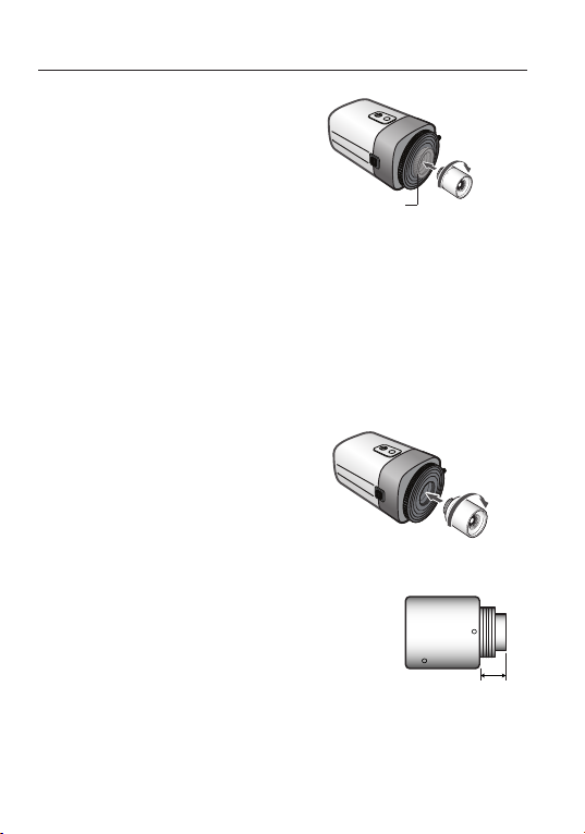
2.
Turn the C-Mount lens clockwise to install it.
C-Mount Adapter
3.
Set focus of camera using Back Focus Control Lever of camera side after combining
C-Mount lens.
Note that C-Mount adaptor is not supplied with camer
When Install a CS-Mount lens
Remove the protective cover from the front of
the camera, and turn the CS-Mount lens
clockwise to install it. And
using Back Focus Control Lever of camera side
after combining CS-Mount lens.
Use the
figure. If the dimensions of the
not correct, it may damage the camera, or the
lens may not be installed firmly.
If the lens is too heavy, the camera becomes
unbalanced and there may be problems. Use
a lens that weighs less than 450g.
14_ Connection
set focus of camera
lens connector shown in the following
connector are
a.
C-Mount Lens:
CS-Mount Lens:
10mm or less
5mm or less
Page 15
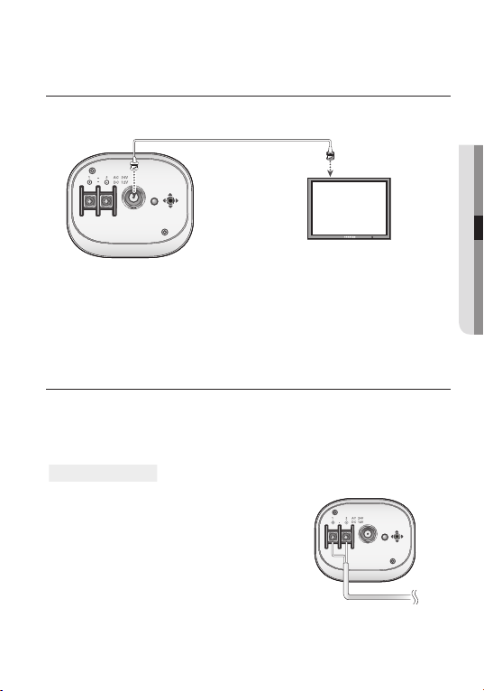
CONNECTING TO MONITOR
Connect the Video OUT port on the rear panel of the camera to a monitor.
POWER
VIDEO
CLASS 2 ONLY
●
CONNECTION
Camera
As the connecting method varies with the instruments, refer to the manual supplied
with the instrument.
Only connect the cable when the power is turned off.
CONNECTING TO POWER
Since power specifications differ depending on the model, make sure to check your model name
and specifications before connecting power.
You can connect power as shown in the following figure.
For AC / DC power
Monitor
CLASS 2 ONLY
SCB-2005
VIDEO
Power
POWER
English_15
Since SCB-2005 the power specification
•
supports
both AC and DC, connect AC 24V, 500mA Adaptor
or DC 12V, 500mA Adaptor.
Page 16
Connection
For DC power
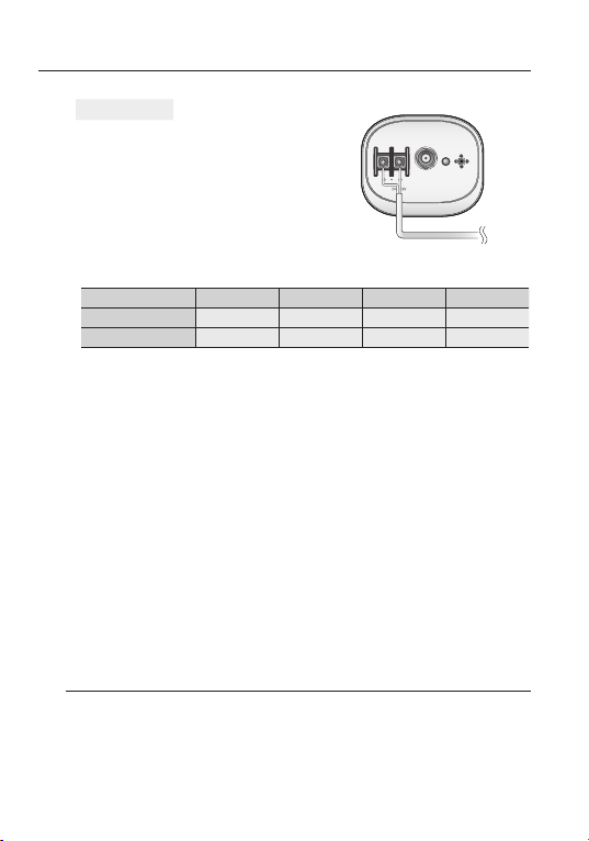
• Since SCB-2005D the power specification
support DC, connect
DC 12V, 500mA
Adaptor.
When the resistance value of copper wire is at [20°C(68°F)]
Copper wire size (AWG)
Resistance (Ω/m)
Voltage Drop (V/m)
• As shown in the table above, voltage decreases as the wire gets longer.
Therefore use of an excessively long adaptor output line for connection to the
camera may affect the performance of the camera.
Standard voltage for camer
SCB-2005N / SCB-2005P : DC 12V±10%, AC 24V±10%
SCB-2005ND / SCB-2005PD : DC 12V±10%
There may be some deviation in voltage drop depending on the type of wir
manufacturer.
Be sur
e to connect po
Note that AC / DC adaptor is not supplied with camera.
Ground should be connected to the GND terminal.
#24(0.22mm2) #22(0.33mm2) #20(0.52mm2) #18(0.83mm2)
0.078 0.050 0.030 0.018
0.028 0.018 0.011 0.006
a operation :
wer only after all the installation is complete.
Using coaxial communications
Coaxial Communications System
•
• OSD Control method
SCB-2005D
VIDEO
Power
POWER
e and the
16_ Connection
Page 17
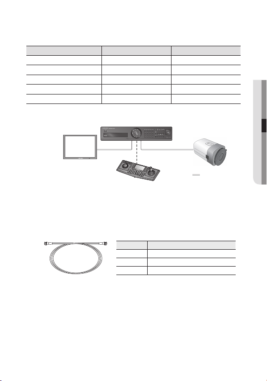
CAMERA DVR CONTROLLER
SET MENU/ENTER OSD KEY
UP UP KEY JOYSTICK UP
DOWN DOWN KEY JOYSTICK DOWN
LEFT LEFT KEY JOYSTICK LEFT
RIGHT RIGHT KEY JOYSTICK RIGHT
DVR
ALARM HDD NETWORK BACKUP REC
REC
1234
ZOOM
FREEZE
BACKUP
SEARCH
5678
1112
910
TELE WIDE
VIEW PRESET
MODE
AUDIO
ALRAM
MENU
15 16
DVD RECORDER
13 14
OPEN/CLOSE
M
E
NU
S
E
A
R
C
H
M
U
L
TI
R
E
C
C
A
M
M
O
N
P
T
Z
D
1
V
R
M
2
T
X
3
SET
U
P
6
4
7
5
8
ESC
9
0
USB
RETURN
ME
N
U
PR
ES
ET
G
R
O
U
P
T
R
A
C
K
FU
N
C
EN
T
ER
C
LO
S
E
O
P
EN
N
E
A
R
F
A
R
W
ID
E
T
E
LE
%1&
56
- Video Cable
The camera's video output port is connected to the monitor with a BNC coaxial cable,
shown below : If the distance between the camera and the monitor exceeds the
recommended maximum, please use an auxiliary video amp.
Distance
It is recommended that pure copper coax cable is used and not copper coated
steel, as this will cause issues with the communication o
To ensure picture quality, only single-channel video output connector can be
used while camera connected to other video equipments.
Recommended Cable Specification
300m 3C2V(RG-59/U)
450m 5C2V(RG-6/U)
600m 7C2V(RG-11/U)
ver the coaxial cable.
●
CONNECTION
English_17
Page 18
Setup
MENU CONFIGRATION
mAIN seTUp
DC
leNs
expOsURe
defOG
WhITe bAl
bACKlIGhT
SSNR3
y/NIGhT
dA
speCIAl
exIT
●
● ●
BRIGHTNESS SHUTTER
● ●
SENS-UP RETURN
● ●
OFF AUTO
ATW
● ●
● ●
MANUAL
● ●
Off
USER BLC
● ●
ON
● ●
AUTO
● ●
IMAGE ADJ
● ●
MOTION DET
SSDR
● ●
SA
VE
● ●
meNU seTUp
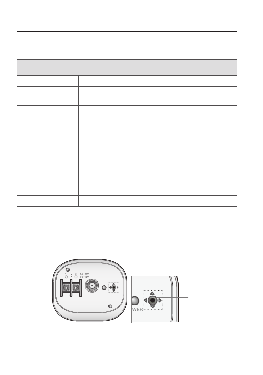
Use the Function Setup switch within the camera.
POWER
VIDEO
CLASS 2 ONLY
MANUAL
●
OUTDOOR INDOOR
→
AWC
OFF
COLOR
CAM TITLE
SYNC
RETURN
NOT SAVE
SET
●
AGC
●
MANUAL
●
●
HLC
●
B/W
●
PRIVACY
●
COAX
RESET
●
Function Setup switch
Press the Function Setup switch.
1.
y
Main setup menu is displayed on the monitor screen.
18_ Setup
Page 19
䯝
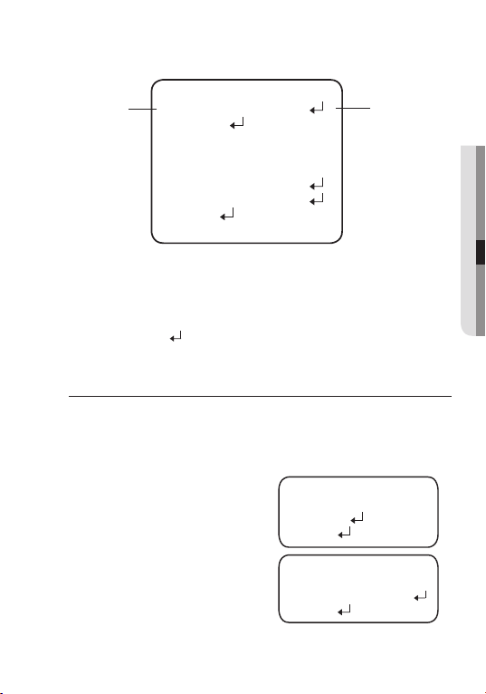
Select the function using
the Function Setup switch.
1.LENS DC
2.EXPOSURE
3.
DEFOG
4.
WHITE BAL ATW
BACKLIGHT OFF
5.
SSNR3 ON
6.
DAY/NIGHT AUTO
7.
OFF
8.SPECIAL
9.EXIT SAVE
MAIN SETUP
Select a desired function using the Function Setup switch.
2.
y
Place the cursor over a desired item.
3.
Set up a selected item by using the Function Setup switch.
4.
To fi
nish the setting, select ‘EXIT’ and press the Function Setup switch.
An item with the icon also has sub menus. To select a sub menu, select an item with the icon
and press the Function Setup switch.
An item with the - - - icon is unavailable due to function settings.
LENS
Using this function, you can choose lens type.
1.
When the SETUP menu screen is displayed, select ‘LENS’ by using the Function
Setup
switch so that the arrow indicates ‘LENS’.
Select the connected lens type by using the Function Setup switch.
2.
DC :
Select Auto Iris Lens.
y
Manual : Select Manual Lens.
y
- Brightness (DC, Manual) : Adjusts the video
- FOCUS ADJ (DC) : To adjust the DC lens focus
- RETURN (
DC, MANUAL) : Select this to save the menu settings and return the MAIN
brightness.
correctly, you must activate the
Focus ADJ mode under each lens
menu. To setting the Focus ADJ
mode on, and according to your
need to adjust the shutter mode.
(MANUAL, A.FLK)
SETUP menu.
BRIGHTNESS
1.
▶
2.
FOCUS ADJ
3.
RETURN
1.
▶
MODE
2.
SHUTTER
3.
RETURN
DC LENS
FOCUS ADJ
Change the status
using the Function
Setup switch.
IIIIIIIII*IIIIIIII
10
ON
ESC
English_19
●
SETUP
Page 20
Setup
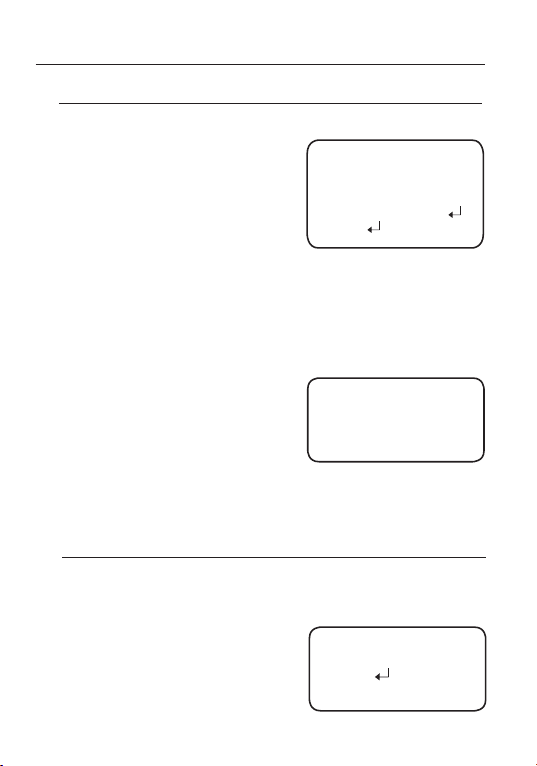
EXPOSURE
1.
When the SETUP menu screen is displayed, select EXPOSURE by using the Function
Setup switch so that the arrow indicates
Select a desired mode using the Function
2.
Setup switch.
BRIGHTNESS : Adjusts the video brightness.
SHUTTER :
AGC (AUTO GAIN CONTROL) (OFF/ LOW/ MIIDDLE/ HIGH) :
RETURN :
You can select the shutter.
-
A.FLK :
Select this when you experience
picture fl
icker, which can happen
when there is a clash with the
frequency of the installed lighting.
-
-
the brighter screen but the higher noise.
SENS-UP : When it is night or dark,the camera
- OFF : Deactiv
- AUTO : Activates the SENS-UP function.
You can control shutter speed manually.
MANUAL :
( NTSC MODEL : 1/60~1/120,000 , PAL MODEL : 1/50~1/120,000)
--- :-Shutter speed is fixed.
ESC :
Select this to control the shutter speed automatically.If ESC is selected,
the shutter speed is automatically controlled depending on the ambient
illumination of the subject.
automatically detects the light level and
maintains a clear picture if this model is
activated.
ates the SENS-UP function.
Select this to save the changes in the EXPOSURE menu and return to the SETUP menu.
When the AGC is set to OFF
When the SENS-UP is set to OFF,
'EXPOSURE'.
EXPOSURE SETUP
BRIGHTNESS
IIIIIIIII*IIIIIIII
䯝 1.
2.SHUTTER
3.AGC MIDDLE
4.SENS-UP
5.RETURN
The higher gain level,
LIMIT
AUTO
(x2
x512)
~
SENS-UP will be disabled.
,
the SHUTTER optional mode is A.FLK,MANUAL or ---.
Press SET to Return
AUTO
---
10
x2
defOG
Through the defogging function, camera can automatically r
self correct in hazy
1. When the SETUP menu screen is displayed, select ‘DEFOG’ by using the Function Setup switch.
2. Select a desired mode.
, rainy, flue gas and other inclement weather to get a clear image.
AUTO :
The camera will automatically correct image
according to the defogging level (low, middle,
high) set by the user.
Manual : The camera will adjust the definition of the
image according to user's preferences
through the defogging level
OFF: Turn off Defogging function.
(low, middle, high).
20_ Setup
ecognize fog concentration of the image, defog,
DEFOG SETUP
1.
LEVEL
2.RETURN
MIDDLE
Page 21
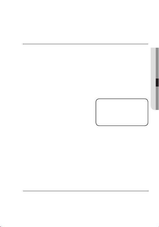
Defogging and SSDR function cannot be run simultaneously. When defogging function is set
to AUTO or MANUAL mode, SSDR function is not available. When SSDR functions is turned
on, defogging would become inactive
.
WHITE BAL (WHITE BALANCE)
Use the White Balance function to adjust the screen color.
1.
When the SETUP menu screen is displayed, select ‘White Bal’ by using the Function
Setup
switch so that the arrow indicates ‘White Bal’.
Select a desired mode using the Function Setup switch.
2.
※
Select one of the following 5 modes, as appropriate for your purpose.
ATW : Select this when the color temperature is between 1,800°K and 10,500°K.
y
y
y
y
y
OUTDOOR :
INDOOR
MANUAL :
AWC→SET
Select this when the color temperature is between 1,800°K and
10,500°K.(sodium light inclusion)
: Select this when the color temperature is between 4,500°K and 8,500°K.
Select this to fi
Balance manually. Set White
Balance fi rst by using the ATW
or AWC mode. After that switch
to MANUAL mode, fi ne-tune the
White Balance and then press
the Function Setup switch.
:
mode.
1
Wh
en the color temperature of the environment surrounding the subject is out of
the control range (e.g. clear sky or sunset).
2
When the ambient illumination of the subject is dim.
the camera is directed towards a fluorescent light or is installed in a
➌
If
place where illumination changes dramatically, the White Balance
operation may become unstable.
ne-tune White
To fi nd the optimal luminance level for the current environment,
point the camera towards a sheet of white paper and press the
Function Setup switch. If the environment changes, readjust it.
WB MANUAL
䯝 RED GAIN
BLUE GAIN
Press SET to Return
IIIIII
IIIIII IIIIIIIIIIIIII
*
IIIIIIIIIIIIIIIII*IIIIIIIIII
White Balance may not work properly under the following conditions.In this case select the AWC
117
193
BACKLIGHT
The SCB-2005 is designed to deliver a distinctive
same time, even when the subject is backlight, by adopting
W6 DSP chip.
1.
When the SETUP menu screen is displayed, select ‘BACKLIGHT’ by using the
Function
Setup switch so that the arrow indicates BACKLIGHT .
subject and background at the
a function of the proprietary
English_21
●
SETUP
Page 22
Setup
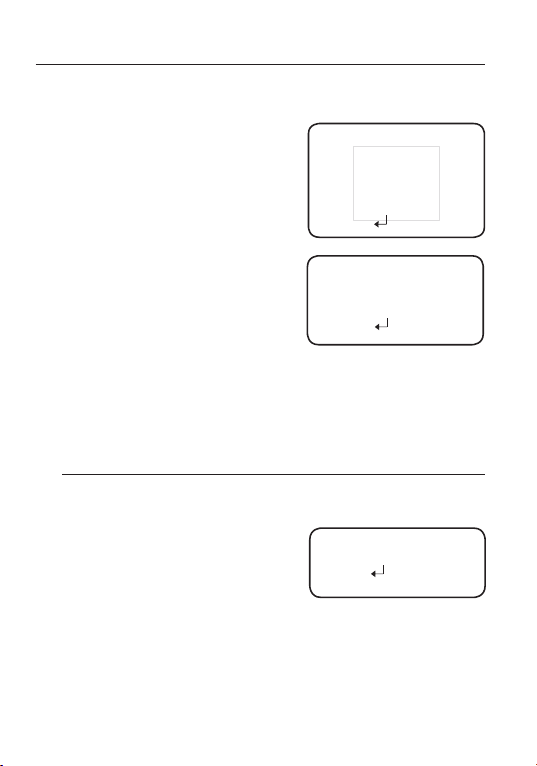
-
MA
SK COLOR
:
Off :
Not being used
Ch
ange the color of the masking area. (Black, Red, Blue, Gray, Magenta)
Select a desired mode using the Function Setup switch depending on the camera
2.
purpose.
U
-
-
:
seR blC
Enables a user to directly
select a desired area from a
picture, and to view the area
more clearly.
LEVEL : Adjust level of the BLC function.
TOP/BOTTOM/LEFT/RIGHT :
Adjust the area to be enhanced.
lC (High light Compensation) :
H
This function masks the strong light to
minimize white out due to over exposur
preserve much of the on-screen details when
the camera aims a strong light source.
VEL : Adjusts the brightness level of a
-
LE
monitoring area.
En
able to change the operating condition.
-
LIMIT :
e and
▶ 1.LEVEL
2.TOP
3.BOTTOM
4.
5. RIGHT
6. RETURN
1. LEVEL
▶
2. LIMIT
3. MASK COLOR BLACK
4. RETURN
LEFT
B
L
HLC SETUP
C SETUP
IIIIIIIIIIIIIIIIIIIII
IIIIIIIIIIIIIIIIIIIII
IIIIIIIIIIIIIIIIIIIII
IIIIIIIIIIII
DDLE
MI
24
25
IIIII
IIII
MIDDLE
NIGHT ONLY
9
84
6615
This function reduces the backgr
1.
When the SETUP menu screen is displayed,
Setup switch so that the
2.
Select a desired mode using the Function Setup
switch.
Off : Deactivates SSNR3. Noise is not reduced.
ON : Activates SSNR3 so that noise is reduced.
3. Set the SSNR3 mode to 'ON' and press the Function Setup switch.
Then you can adjust the noise reduction level.
4.
You cannot set the SSNR3 to 'ON' or 'OFF' when the AGC mode of the EXPOSURE
menu is 'OFF'.
When adjusting the noise reduction level of the SSNR3 mode, r
the level set, the mor
22_ Setup
ound noise in a low luminance environment.
arrow indicates 'SSNR3'.
e the noise level will be reduced but that after image may also occur.
select 'SSNR3' by using the Function
▶
LEVEL
1.
2.
RETURN
SSNR3
IIIIIIIIIII
IIIIIIII
IIIIII
22
emember that the higher
Page 23
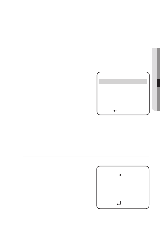
DAY/ NIGHT
You can display pictures in color or black and white.
1. When the SETUP menu scr
and Down buttons so that the arrow indicates ‘DAY/NIGHT’.
2. Select a desired mode using the Left and Right buttons accor
you want.
AUTO
: The mode is switched to ’Color‘ in a normal environment, but switches to
’B/W‘ mode when ambient illumination is low. To set up the switching time
or AUTO mode, press the Function Setup switch. You can turn on or off
f
the burst signal on B/W mode.
-
BURST MODE :
burst signal on B/W mode.
TION :
-
DURA
level at which the camera switches from day
to night mode.
-
DWELL TIME :
time about changing the day/night mode.
→3s, 5s, 7s, 10s, 15s, 20s, 30s, 40s, 60s
COlOR : The picture is always displayed in color.
b/W : The picture is always displayed in black and white.
burst mode on B/W mode.
een is displayed, select ‘DAY/NIGHT’ by using the Up
ou can turn on or off the
Y
ou can select the brightness
Y
You can select the duration
▶1.BURST MODE ON
2.COLORB/W
DURATION FAST
DWELL TIME 5 SEC
3.B/WCOLOR
DURATION FAST
DWELL TIME 10 SEC
4.RETURN
You can turn on or off the
ding to the picture display
SPECIAL
1. When the SETUP menu screen is displayed, select ‘SPECIAL
switch
so that the arrow indicates ‘SPECIAL’.
2. Select a desir
switch.
ed mode using the Function Setup
’ by using the Function
▶ 1
IMAGE ADJ
.
CAM TITLE
2.
3.
PRIVACY
MOTION DET
4.
5.
SYNC
COAX
6.
SSDR
7.
RETURN
8.
A
UTO SETUP
SPECIAL
Setup
OFF
OFF
OFF
INT
OFF
OFF
●
SETUP
English_23
Page 24
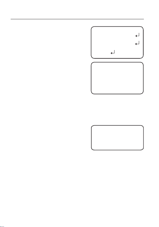
Setup
IMA
ADJ
GE
1) When the SPECIAL menu screen is displayed,
‘IMAGE ADJ’ by using the Function Setup
select
switch so that the arrow indicates ’IMAGE
2) Select a desired mode using the Function Setup
switch.
-
monitor : Please change the settings value
of video appropriate to your monitor.
LCD: Please select this menu item when
using an LCD
the gamma, PED level and color gain in
the sub menus.
USER : Please use this menu item when
using a monitor other than standard ones.
You can change the gamma, PED level and color gain in the sub menus.
-
ReVeRse : You can r
OFF : You don’t reverse the picture.
H-REV : You can flip the picture horizontally on the screen.
-
shARpNess
picture outline becomes stronger and clearer.
Adjust this
the sharpness of the picture.
OFF: Tur
ON : The higher the level is,the sharper and
ER (Enhanced Resolution) : Choosing this mode can increase the sharpness of the picture
-
lANGUAGe
-
RUTURN
monitor. You can change
everse the picture.
: As you increase this value, the
value appropriately depending on
n off Sharpness function.
clearer the outline of the image becomes.
: You can select the menu language according to your requirements.
:
Select this to save the
menu.
▶ 1.MONITOR
ADJ‘.
3.
5.
▶ GAMMA 0.55
PED LEVEL
COLOR GAIN 7
RESET
▶ 7
under the colour mode.
menu settings and return to the SPECIAL
IMAGE ADJ
IMAGE SETUP
LCD
2
.
REVERSE
SHARPNESS ON
LANGUAGE
4.
RETURN
LCD MONITOR
1
.
2.
.
3
4.
LEVEL
IIIIIIIII*IIIIIIIIIIII
Press SET to Return
SHARPNESS
Press SET to Return
IIIIIIIIIIIIIIIIII III
OFF
ENGLISH
45
III*IIIIIIIIIIIIIIIIII
24_ Setup
Page 25
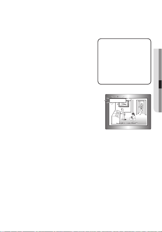
CAm
TITle : If you enter a title, the title will appear on the monitor.
1 If the SPECIAL menu scr
that the arr
2
3 Press the Function Setup switch.
4
5 Enter a title, move the cursor to ’POS’ and press
ow indicates ‘CAM TITLE’.
Set it to ‘ON’ by using the Function
Setup switch.
Use the Function Setup switch to move to a
desired letter and select the letter by pressing
the switch. Repeat this to
You can enter up to 15 letters. Move
cursor to
↑
for entering a space, then press
Setup switch, the cursor will skip
the Function
to the next.
the Function Setup switch. The enter
een. Select the position to display the title
on the scr
on the screen
and press. When the position is determined, select
’END’ and press the Function Setup switch to
eturn to the SPECIAL menu.
r
een is displayed, use the Function Setup switch so
enter multiple letters.
the
ed title appears
by using the Function Setup switch
CAMERA TITLE SETUP
ABCDEFGHIJKLM
NOPQRSTUVWXYZ
abcdefghijklm
nopqrstuvwxyz
0
-
.
123456789
/
← → C
LR POS END
_______________
FRONT DOOR
●
SETUP
WhentheCAMTITLEmenuis‘OFF’,notitlewillbedisplay
if you enter one.
OnlyEnglishisavailableinthismode.
vethecursortoCLRandpresstheFunctionSetupswitch,allthelettersare
Ifyoumo
deleted. To edit a letter, change the cursor to the bottom left arrow and press the
FunctionSetupswitch.Movethecursoroverthelettertobeedited,movethecursorto
thelettertobeinsertedandthenpresstheFunctionSetupswitch.
on
ed
themonitorscreeneven
English_25
Page 26
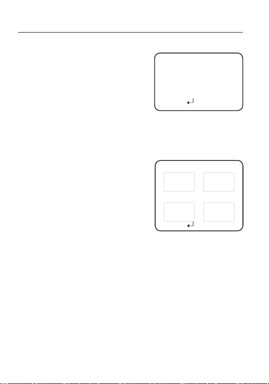
Setup
pRIVACy : Mask an area you want to hide on the screen.
When the SPECIAL menu screen is displ-
1
ayed, pr
the Function Setup switch so
ess
that the arrow indicates ‘PRIVACY’.
2
Set up the mode using the Function Setup
switch.
-
AREA : You can select up to 8 PRIVACY ar
- MODE : Determines whether to use the ar
selected.
MASK COLOR : Determine area color. You can select GREEN, RED, BLUE, BLACK,
-
- SEL POS/POS
- RETURN : Select this to save the PRIV
WHITE and GRAY
: Adjust the size and position of the selected area.
menu.
PRIVACY AREA SETUP
▶ 1.AREA
2.MODE OFF
3.MASK COLOR WHITE
4.SEL POS LEFT
eas.
5.POS
ea
6.RETURN
AREA1
IIIIIIIIIIIIIIIIIIIIIIIIII
*
.
ACY menu settings and return to the SPECIAL
9
y
26_ Setup
MOTION DET :
2
This product has a feature that allows
you to observe movement of objects
in 4 different areas on the screen,
and the words 'MOTION DETECTED'
appear on the screen when movement
You can monitor activity
is detected.
1
more efficient.
When the SPECIAL menu screen is displayed,
press the Function Setup switch so
arrow indicates 'MO
Set up the mode using the Function Setup switch.
AREA:
MODE:
TOP/BOTTOM/LEFT/RIGHT:
SENSITIVITY:
RETURN :
MOTIONDETareasshowonly MOTIONDET menu. Therefore,MOTIONDET areas don’t
display on the monitor screen.
TION DET'.
canselectup to 4 MD areas.
You
DetermineswhethertousetheMDareaselectedinAREA.
Adjust the sensitivity of MD. the lower level, the higher sensitivity.
Select this to save the MOTION DET menu settings and return to the SPECIAL
menu.
that the
Adjust the area to be enhanced.
MOTION DET
1.AREA AREA1
2.MODE
3.TOP
4.BOTTOM
5.LEFT
6.RIGHT
ITIVITY
7.SENS
8.RETURN
IIIIIIIIIIIIIIIIIIIII
IIIIIIIIIIIIIIIIIIIII
IIIIIIIIIIIIIIIIII
ON
4
IIIIIIIIIIIIIII IIIIII
15
9
IIIIIIIIIIIIIII IIIIII
46
III
4
Page 27
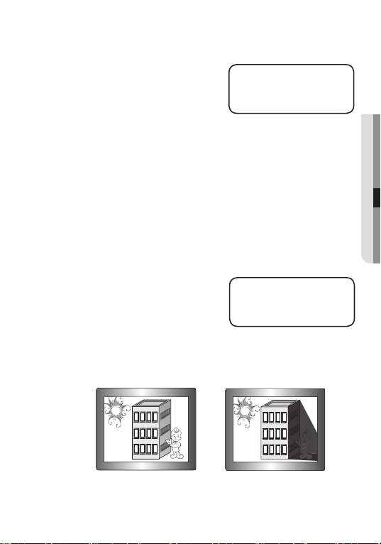
syNC : In areas wher
60Hz(NTSC), 50Hz(PAL), you can
synchronize the output phase of multiple
cameras using the power synchr
e the supply is at
onization
▶ PHASE
SYNC
IIIIIIIIIIIIIIIIIIIII
*
Press SET to Return
function (Line-Lock) without using a
synchronization signal generator
INT: Internal Synchronization Type
-
.
- L/L : Power Synchronization Type, Line-lock
Press the Function Setup switch.
You can select a desired phase from 0 to 359 when select ‘phase’.
When using AC power at 60Hz(NTSC),
synchronization.
When the power is DC 12V, the SYNC menu is fixed to the ‘INT’ mode.
COaX : COAX option is set to "On" will specify the use of coaxial communication.
SSDR(Samsung Super Dynamic Range)
SSDR illuminates darker ar
etaining the same light level for brighter areas to
r
even out the overall brightness of images with
high contrast between bright and dark areas.
1.
When the SETUP menu screen is displayed, select ‘SSDR’ by using the
eas of an image while
50Hz(PAL) frequency, you can use the L/L type
▶ LEVEL
SSDR SETUP
IIIIIIIIII*IIIIIIIIIII
Press SET to Return
:
Function Setup switch so that the arrow indicates ‘SSDR’.
Use the Function Setup switch to change the SSDR level in the sub menu according to
2.
the contrast between bright and dark areas.
0
●
SETUP
8
SSDR ON
SSDR OFF
RETURN : Select this to save the SPECIAL menu settings and return to the MAIN
SETUP
menu.
English_27
Page 28

Setup
EXIT
Select a desired EXIT mode using the Function Setup switch depending on the camera purpose.
sAVe : Save the current settings and exit the MAIN SETUP menu.
NOT sAVe : Do not save the current settings and exit the MAIN SETUP menu.
: Resets the camera settings to the factory defaults. Monitor, Language
ReseT
and COAX
settings are
not initialized.
28_ Setup
Page 29
Troubleshooting
TROUBLESHOOTING
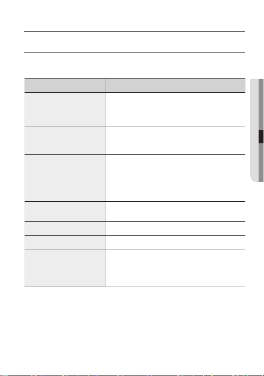
If you have trouble operating your camera, r
you to solve the problem, contact an authorized technician.
PROBLEM
Nothing appears on the screen.
The image on the screen is dim.
The image on the screen is dark.
The camera is not working
properly, and the surface of the
camera is hot.
The DAY/NIGHT function does
not work.
Color is not correct.
The screen fl ickers continually.
When coaxial communication is
not available
efer to the following table. If the guidelines do not enable
▶ Check that the power cord and line connection between the
camera and monitor are fi
▶ Check that you have properly connected VIDEO cable to the
camera VIDEO output jack.
▶ Is the lens stained with dirt? Clean your lens with a soft, clean cloth.
▶
Check the monitor and DVR settings.
▶
If the camera is exposed to very strong light, change the camera position.
▶ Adjust the contrast feature of the monitor or DVR.
If you have an intermediate device, set the 75Ω / Hi-z properly.
▶
▶ Check that you have properly connected the camera to an
appropriate power source.
▶
Check that
AGC of EXPOSURE SETUP menu is ‘OFF’.
▶ Check the setting of WHITE BAL SETUP menu .
▶ Check that the camera is not pointing at the sun.
▶ Make sure that the camera and monitor are installed within
the recommended distance.
▶
Use the video amplifi er equivalent to coaxitron if the
recommended installation distance is exceeded.
SOLUTION
xed properly.
●
TROUBLESHOOTING
English_29
Page 30
Specifications
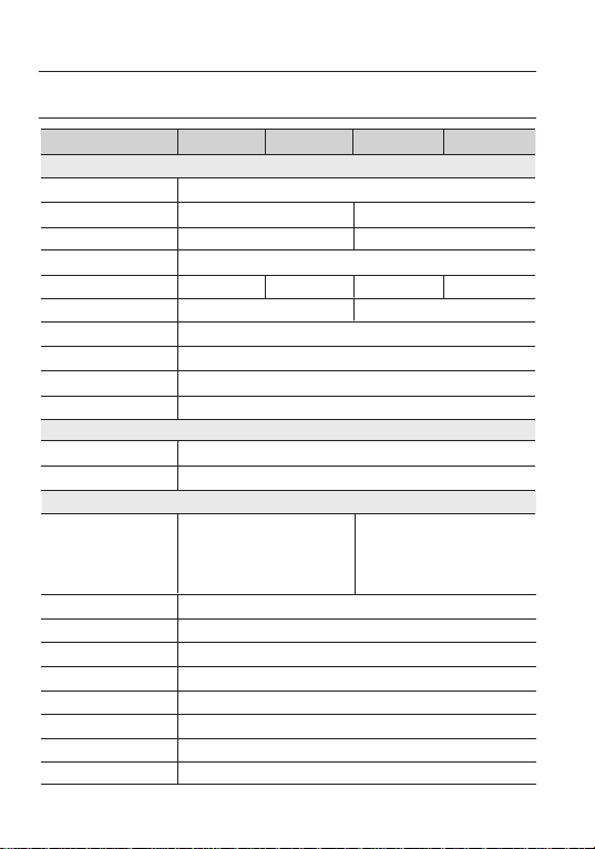
SPECIFICATIONS
Video
Imaging Device
Total Pixels
Effective Pixels
Scanning System
Synchronization
Frequency
Horizontal Resolution
Min. Illumination
/ N Ratio
s
Video Output
Lens Type
Lens Type
Mount Type
Operational
On Screen Display
Camera Title
Day & Night
Backlight Compensation
Contrast Enhancement
Digital Noise Reduction
Defog
Motion Detection
Privacy Masking
6&%1' 6&%3'
1/3’’ Super HAD CCD II (Double Scan)
1020(H) x 508(V)
976(H) x 494(V)
2:1 Interlace
Internal
H : 15.734KHz / V : 59.94Hz
700 TV lines(ER Mode)
0.1Lux ([email protected]) / 0.0002Lux ([email protected], SENS-UP x512)
52dB (AGC off, Weight on)
CVBS : 1.0Vp-p, 75Ω composite
Manual / Auto Iris (DC)
C / CS
English, Japanese, Spanish,
French, Portuguese, Korean
Off / On (Displayed 15 characters)
Auto (ICR) / Color / B/W
OFF / USER BLC / HLC
SSDR ( Off/On )
3D DNR ( Off/On )
Off / Auto / Manual
Off / On
Off / On (8 programmable zones)
6&%1 6&%3
1020(H) x 596(V)
976(H) x 582(V)
Internal
H : 15.625KHz / V : 50Hz
English, French, German, Spanish,
Italian, Chinese, Russian, Polish,
Czech, Romanian, Serbian,
Swedish, Danish, Turkish,
Portuguese
Internal / Line LockInternal / Line Lock
30_ Specifi
cations
Page 31
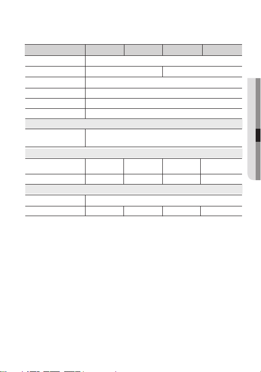
Gain Control
Electronic Shutter Speed
White Balance
Reverse
Communication
Protocol
Environmental
Operating Temperature
/ Humidity
Electrical
Electrical
Input Voltage
Current
Mechanical
Mechanical
Dimension(WxHxD)
Weight
※
This specifi
cation can be changed without notice for performance improvement of product.
6&%1' 6&%1 6&%36&%3'
Off / Low / Middle / High
1/60 ~ 1/120,000
ATW / Outdoor / Indoor / Manual / AWC
sec
1/50 ~ 1/120,000
→
sec
SET (1,800K° ~ 10,500K°)
OFF / H-REV
Coaxial Control ( SPC-300 Compatible )
Coax : Pelco-C ( Coaxitron )
-10°C ~ +55°C (+14°F ~ +131°F) / Less than 90% RH
DC 12V±10%
0.23A
92.7 x 68.4 x 59.6mm
13 3 g
AC 24V ± 10% ,
DC 12V±10%
0.3A 0.23A
150g
DC 12V±10%
13 3 g
AC 24V ± 10% ,
DC 12V±10%
0.3A
150g
●
SPECIFICATIONS
English_31
Page 32
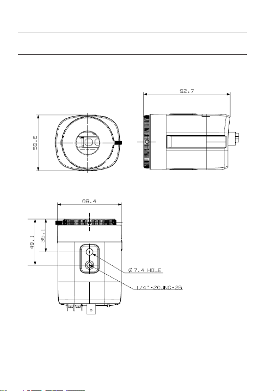
Specifications
DIMENSION
Unit: mm
32_ Specifi
cations
Page 33
SALES NETWORK
SAMSUNG TECHWIN CO., LTD.
Samsung Techwin R&D Center, 6, Pangyo-ro 319beon-gil, Bundang-gu, Songnam-si, Gyeonggi-do 463-400, Korea
TEL : +82-70-7147-8740~60, FAX : +82-31-8018-3745
SAMSUNG TECHWIN AMERICA Inc.
100 Challenger Rd. Suite 700 Ridgefield Park, NJ 07660
Toll Free : +1-877-213-1222 Direct : +1-201-325-6920
Fax : +1-201-373-0124
www.samsungcctvusa.com
www.samsungtechwin.com
www.samsungsecurity.com
SAMSUNG TECHWIN EUROPE LTD.
Samsung House, 1000 Hillswood Drive, Hillswood Business Park
Chertsey, Surrey, UNITED KINGDOM KT16 OPS
TEL : +44-1932-45-5300, FAX : +44-1932-45-5325
NO. :
P/
PT01-002001A
 Loading...