

Page 1
SCB-4000(P)
SCB-4000PH
DIGITAL COLOR CAMERA
user manual
imagine the possibilities
Thank you for purchasing this Samsung product.
To receive more complete service,
please register your product at
www.samsungsecurity.com
Page 2
Safety information
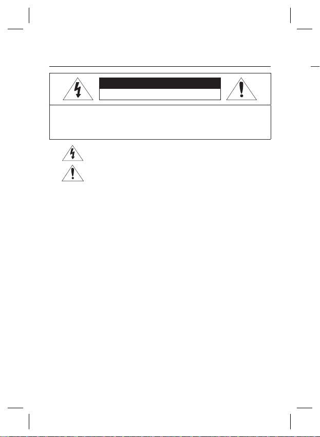
CAUTION
RISK OF ELECTRIC SHOCK.DO NOT OPEN
CAUTION: TO REDUCE THE RISK OF ELECTRIC SHOCK, DO NOT REMOVE
COVER (OR BACK) NO USER SERVICEABLE PARTS INSIDE. REFER
SERVICING TO QUALIFIED SERVICE PERSONNEL.
THIS SYMBOL INDICATES THAT DANGEROUS VOLTAGE CONSISTING A
RISK OF ELECTRIC SHOCK IS PRESENT WITHIN THIS UNIT.
THIS EXCLAMATION POINT SYMBOL IS INTENDED TO ALERT THE USER TO
THE PRESENCE OF IMPORTANT OPERATING AND MAINTENANCE (SERVICING)
INSTRUCTIONS IN THE LITERATURE ACCOMPANYING THE APPLIANCE.
WARNING
TO REDUCE THE RISK OF FIRE OR ELECTRIC SHOCK, DO NOT EXPOSE THIS APPLIANCE TO
•
RAIN OR MOISTURE.
TO PREVENT INJURY, THIS APPARATUS MUST BE SECURELY ATTACHED TO THE FLOOR/WALL
•
IN ACCORDANCE WITH THE INSTALLATION INSTRUCTIONS.
IF THIS POWER SUPPLY IS USED AT 240V AC, A SUITABLE PLUG ADAPTER SHOULD BE USED.
•
WARNING
BE SURE TO USE ONLY THE STANDARD ADAPTER THAT IS SPECIFIED IN THE SPECIFICATIO
1.
USING ANY OTHER ADAPTER COULD CAUSE FIRE, ELECTRICAL SHOCK, OR DAMAGE TO THE PRODUCT.
2.
INCORRECTLY CONNECTING THE POWER SUPPLY OR REPLACING BATTERY MAY CAUSE EXPLOSION,
FIRE, ELECTRIC SHOCK, OR DAMAGE TO THE PRODUCT.
3.
DO NOT CONNECT MULTIPLE CAMERAS TO A SINGLE ADAPTER. EXCEEDING THE CAPACITY MAY
CAUSE ABNORMAL HEAT GENERATION OR FIRE.
SECURELY PLUG THE POWER CORD INTO THE POWER RECEPTACLE. INSECURE CONNECTION MAY
4.
CAUSE FIRE.
WHEN INSTALLING THE CAMERA, FASTEN IT SECURELY AND FIRMLY. THE FALL OF CAMERA MAY
5.
CAUSE PERSONAL INJURY.
DO NOT PLACE CONDUCTIVE OBJECTS (E.G. SCREWDRIVERS, COINS, METAL PARTS, ETC.) OR
6.
CONTAINERS FILLED WITH WATER ON TOP OF THE CAMERA. DOING SO MAY CAUSE PERSONAL
INJURY DUE TO FIRE, ELECTRIC SHOCK, OR FALLING OBJECTS.
DO NOT INSTA
7.
FIRE OR ELECTRIC SHOCK.
8.
IF ANY UNUSUAL SMELLS OR SMOKE COME FROM THE UNIT, STOP USING THE PRODUCT. IN
SUCH CASE, IMMEDIATELY DISCONNECT THE POWER SOURCE AND CONTACT THE SERVICE
CENTER. CONTINUED USE IN SUCH A CONDITION MAY CAUSE FIRE OR ELECTRIC SHOCK.
2 – DIGITAL COLOR CAMERA
2 – DIGITAL COLOR CAMERA
LL THE UNIT IN HUMID, DUSTY, OR SOOTY LOCATIONS. DOING SO MAY CAUSE
N SHEET.
10.
CAUT
1.
2.
3.
4.
5.
6.
7.
8.
9.
W
e
D
s
D
1
If
o
R
c
K
In
A
d
A
v
T
Page 3
d of
Safety information
IF THIS PRODUCT FAILS TO OPERATE NORMALLY, CONTACT THE NEAREST SERVICE
9.
CENTER. NEVER DISASSEMBLE OR MODIFY THIS PRODUCT IN ANY WAY. (SAMSUNG
IS NOT LIABLE FOR PROBLEMS CAUSED BY UNAUTHORIZED MODIFICATIONS OR
ATTEMPTED REPAIR.)
WHEN CLEANING, DO NOT SPRAY WATER DIRECTLY ONTO PARTS OF THE PRODUCT. DOING
10.
SO MAY CAUSE FIRE OR ELECTRIC SHOCK.
CAUTION
DO NOT DROP OBJECTS ON THE PRODUCT OR APPLY STRONG BLOWS TO IT. KEEP AWAY
1.
FROM A LOCATION SUBJECT TO EXCESSIVE VIBRATION OR MAGNETIC INTERFERENCE.
DO NOT INSTALL IN A LOCATION SUBJECT TO HIGH TEMPERATURE (OVER 140°F), LOW
2.
TEMPERATURE (BELOW -14°F), OR HIGH HUMIDITY. DOING SO MAY CAUSE FIRE OR
ELECTRIC SHOCK.
IF YOU WANT TO RELOCATE THE ALREADY INSTALLED PRODUCT, BE SURE TO TURN OFF
3.
THE POWER AND THEN MOVE OR REINSTALL IT.
REMOVE THE POWER PLUG FROM THE OUTLET WHEN THERE IS A LIGHTING STORM.
4.
NEGLECTING TO DO SO MAY CAUSE FIRE OR DAMAGE TO THE PRODUCT.
KEEP OUT OF DIRECT SUNLIGHT AND HEAT RADIATION SOURCES. IT MAY CAUSE FIRE.
5.
INSTALL IT IN A PLACE WITH GOOD VENTILATION.
6.
AVOID AIMING THE CAMERA DIRECTLY TOWARDS EXTREMELY BRIGHT OBJECTS SUCH AS
7.
SUN, AS THIS MAY DAMAGE THE CCD IMAGE SENSOR.
APPARATUS SHALL NOT BE EXPOSED TO DRIPPING OR SPLASHING AND NO OBJECTS
8.
FILLED WITH LIQUIDS, SUCH AS VASES, SHALL BE PLACED ON THE APPARATUS.
THE MAINS PLUG IS USED AS A DISCONNECT DEVICE AND SHALL STAY READILY OPERABLE AT ANY TIME.
9.
FCC STATEMENT
THIS DEVICE COMPLIES WITH PART 15 OF THE FCC RULES. OPERATION IS SUBJECT TO THE
FOLLOWING TWO CONDITIONS :
1) THIS DEVICE MAY NOT CAUSE HARMFUL INTERFERENCE, AND
2)
THIS DEVICE MUST ACCEPT ANY INTERFERENCE RECEIVED INCLUDING INTERFERENCE THAT MAY
CAUSE UNDESIRED OPERATION.
Caution
THIS EQUIPMENT HAS BEEN TESTED AND FOUND TO COMPLY WITH THE LIMITS FOR A CLASS A DIGITAL
DEVICE, PURSUANT TO PART 15 OF FCC RULES. THESE LIMITS ARE DESIGNED TO PROVIDE REASONABLE
PROTECTION AGAINST HARMFUL INTERFERENCE WHEN THE EQUIPMENT IS OPERATED IN A COMMERCIAL ENVIRONMENT.
THIS EQUIPMENT GENERATES, USES, AND CAN RADIATE RADIO FREQUENCY ENERGY AND, IF NOT
INSTALLED AND USED IN ACCORDANCE WITH THE INSTRUCTION MANUAL, MAY CAUSE HARMFUL INTERFERENCE TO RADIO COMMUNICATIONS. OPERATION OF THIS EQUIPMENT IN A RESIDENTIAL AREA IS
LIKELY TO CAUSE HARMFUL INTERFERENCE IN WHICH CASE THE USER WILL BE REQUIRED TO CORRECT
THE INTERFERENCE AT HIS OWN EXPENSE.
IC COMPLIANCE NOTICE
THIS CLASS A DIGITAL APPARATUS MEETS ALL REQUIREMENTS OF THE
CANADIAN INTERFERENCE.-CAUSING EQUIPMENT REGULATIONS OF ICES-003.
English – 3
Page 4
Important Safety Instructions
Read these instructions.
1.
Keep these instructions.
2.
Heed all warnings.
3.
Follow all instructions.
4.
Do not use this apparatus near water.
5.
Clean only with dry cloth.
6.
Do not block any ventilation openings. Install in accordance with the manufacturer’s instructions.
7.
Do not install near any heat sources such as radiators, heat registers, or other apparatus (including
8.
amplifi ers) that produce heat.
Do not defeat the safety purpose of the polarized or grounding-type plug. A polarized plug has two
9.
blades with one wider than the other. A grounding type plug has two blades and a third grounding
prong. The wide blade or the third prong is provided for your safety. If the provided plug does not fi t into
your outlet, consult an electrician for replacement of the obsolete outlet.
Protect the power cord from being walked on or pinched particularly at plugs, convenience
10.
receptacles, and the point where they exit from the apparatus.
Only use attachments/accessories specifi ed by the manufacturer.
11.
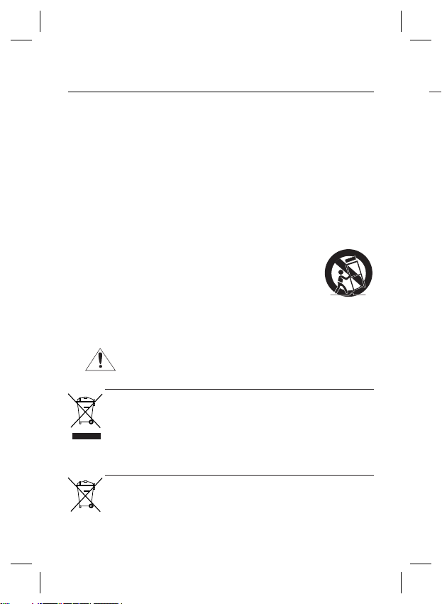
Use only with cart, stand, tripod, bracket, or table specifi ed by the manufacturer, or
12.
sold with the apparatus.
Unplug this apparatus when a card is used. Use caution when moving the cart/
13.
apparatus combination to avoid injury from tip-over.
14.
Refer all servicing to qualifi ed service personnel. Servicing is required when the apparatus has been
damaged in any way, such as powersupply cord or plug is damaged, liquid has been spilled or objects
have fallen into the apparatus, the apparatus has been exposed to rain or moisture, does not operate
normally, or has been dropped.
Apparatus shall not be exposed to dripping or splashing and no objects
fi lled with liquids, such as vases, shall be placed on the apparatus
Correct Disposal of This Product
(Applicable in the European Union and other European countries with separate collection systems)
This marking on the product, accessories or literature indicates that the product and its electronic accessories (e.g.
charger, headset, USB cable) should not be disposed of with other household waste at the end of their working life. To
prevent possible harm to the environment or human health from uncontrolled waste disposal, please separate these items
from other types of waste and recycle them responsibly to promote the sustainable reuse of material resources.
Household users should contact either the retailer where they purchased this product, or their local government office, for
details of where and how they can take these items for environmentally safe recycling.
Business users should contact their supplier and check the terms and conditions of the purchase contract.
This product and its electronic accessories should not be mixed with other commercial wastes for disposal.
Correct disposal of batteries in this product
(Applicable in the European Union and other European countries with separate battery return systems.)
This marking on the battery, manual or packaging indicates that the batteries in this product should not be disposed of
with other household waste at the end of their working life. Where marked, the chemical symbols Hg, Cd or Pb indicate
that the battery contains mercury, cadmium or lead above the reference levels in EC Directive 2006/66. If batteries are
not properly disposed of, these substances can cause harm to human health or the environment.
To protect natural resources and to promote material reuse, please separate batteries from other types of waste and
recycle them through your local, free battery return system.
4 – DIGITAL COLOR CAMERA
(Waste Electrical & Electronic Equipment)
Page 5

Contents
Introduction
Features 6
PRODUCT & ACCESSORIES 7
Part Names and Functions 8
Installation
Connecting the Auto Iris Lens Connector 11
Mounting the lens 11
Connecting cables and checking operation 12
How to use OSD Menu
Using Icons in the Menu 13
Main Menu 13
Profi le 14
Camera Setup 16
Intelligence 22
Privacy Zone Setup
Other Set 25
Communication 26
System Information 26
Specifi cations
Specifi cations 28
24
English – 5
Page 6

Introduction
FEATURES
High Resolution
❖
This camera has realized high resolution of 600 lines using the top-notch full digital image processing and
•
special algorithm technologies.
Intelligent Motion Detection & Tracking
❖
•
This is an intelligent function that automatically detects a motion of an object. You can set a virtual fence so it
sounds an alert if an object passes / enters /exits the virtual fence or virtual area.
❖
XDR (eXtended Dynamic Range)
Actively controls the gamma compensation in the way it operates the ambient luminance contrast in a
•
certain pixel unit to determine the optimal visibility.
DAY/NIGHT
❖
•
This function can make the IR Cut fi ltering function inactive under the illumination below the normal value.
❖
High Sensitivity
It implements images of high sensitivity using the up-to-date SONY 1/2”Exview-HAD IT CCD..
•
Low Illumination
❖
It uses the digital signal technologies such as low illumination and Day/Night functions that make your camera
•
identify objects even in the worst environment.
Superior Backlight Adjustment
❖
•
When an object has a bright illumination or sunlight behind it, this camera automatically improves the
shaded object picture quality.
❖
Digital Power Synchronization
The full digital Line Lock function directly adjusts the vertical camera synchronization to enhance the
•
operationability and reliability of this camera.
Output Signal Setting
❖
You can set the following Video output signals: Image reversion (Horizontal, Vertical, or both), Privacy,
•
Horizontal/Vertical profi ling, and digital zooming.
OSD(On Screen Display) Menu
❖
•
OSD menu is provided to display the status of camera and to confi gure the functions interactively.
Coaxial Cable Communication
❖
This is a remote control function that overlaps the coaxial cable (for a transfer of the video signal) with the
•
control signal. In installation or repair, this helps you control the communication controller (optional) without
additional cabling.
PRO
P❖
•
•
Came
6 – DIGITAL COLOR CAMERA
Page 7
Introduction
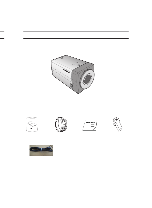
PRODUCT & ACCESSORIES
Product & Accessories❖
Main Product
•
Camera
Accessories
•
Camera Holder(Mount)
t
(SCB-4000PH)
POWER
C Mount Adapter
User’s Manual
Auto Iris
Lens Connector
English – 7
Page 8
Introduction
PART NAMES AND FUNCTIONS
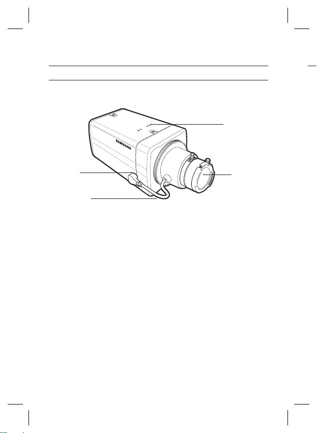
Side View❖
Mount Adapter
Fixing Grooves
R❖
Auto Iris Lens
Connector
Auto Iris Lens
Control Cable
Auto Iris Lens Connector
•
This groove is used for screwing the mount adapter, a part of the bracket where the camera will be installed.
Auto Iris Lens Control Cable
•
This cable transmits the power and signals from the camera for controlling the Auto Iris Lens.
Mount Adapter Fixing Grooves
•
These grooves are used when fi xing screws of the mount adapter connected to the bracket when installing
the camera on it.
Note :
When the camera lens becomes dirty, softly clean it with a lens tissue or a cloth soaked in pure ethanol.
–
8 – DIGITAL COLOR CAMERA
Camera Lens
Page 9
Introduction
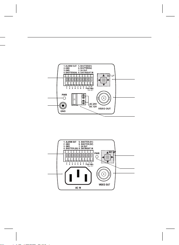
Rear Panel❖
<AC24/DC12V (SCB-4000(P))>
n
p
r
<AC220V~240V(SCB-4000PH)>
ing
n
s
o
q
s
o
p
q
English – 9
Page 10
Introduction
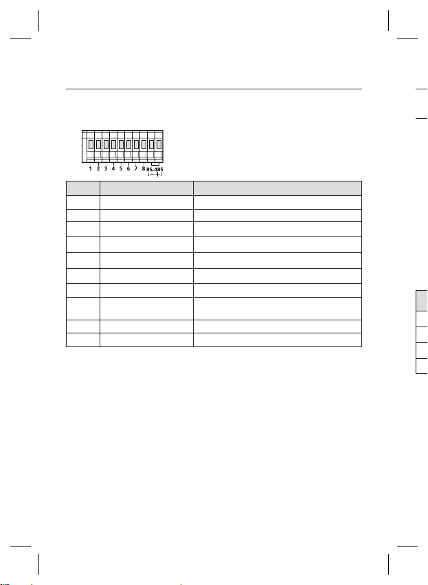
n Input/Output Connector
This connector has input and output ports for RS-485 control signals, DAY/NIGHT switching, and alarm
output signals.
No. Function Description
1 ALARM OUT
2 GND Grounding Port.
3 GND Grounding Port.
4 SHUTTER (S0)
5 SHUTTER (S1)
6 SHUTTER (S2)
7 5V OUT
8
9 RS-485 DATA-
10 RS-485 DATA+
o SETUP Switch
This switch is used to set the function or property. When this switch is pressed for at least 2 seconds, the
MAIN MENU appears.
ef
(Left/Right)
cd
(Up/Down) :
: When you press this switch in the menu, the selected function is confi rmed. To enter a submenu, press
this button.
p Power Display LED
When the power is normally connected, the red LED lights.
q Video OUT Port
This is connected to the Video Input Port of the monitor and it outputs the Video signals.
r GND
This is a grounding port.
s Power Connection Port
This is connected to the Power cable.
DAY/NIGHT IN
: By pressing this switch left or right, you can move left or right on the menu or change the
displayed value.
By pressing this switch up or down, you can move up or down on the menu.
10 – DIGITAL COLOR CAMERA
Alarm out port for motion detection. (Open collector type)
This is a port for selecting an external high speed shutter mode.
If connected in LOW (0V), it will become ON inside.
This is a port for selecting an external high speed shutter mode.
If connected in LOW (0V), it will become ON inside.
This is a port for selecting an external high speed shutter mode.
If connected in LOW (0V), it will become ON inside.
Power supply port for RS-485 JIG. Use within typical DC +5V 100mA
This is a port for DAY&NIGHT conversion.
High(DC +3V~+5V) : DAY(COLOR) Mode,
Low(0V) : NIGHT(BW) Mode
This is a port for connection to RS-485 DATA- signal line.
This is a port for connection to RS-485 DATA+ signal line.
CO
CO
Conn
the A
P
N
1
2
3
4
No
–
Page 11
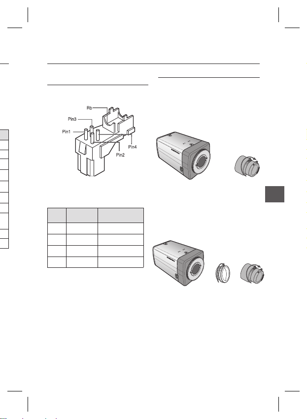
CONNECTING THE AUTO IRIS LENS
CONNECTOR
Installation
MOUNTING THE LENS
When using the CS lens
Mount the CS lens by rotating it clockwise as shown
in the picture:
CS lens
CS 렌즈
Connect each uncovered shutter control cables to
the Auto Iris Lens Connector as the following
Pin
DC Control
No.
1 Damp(-) Power (+12V)
2 Damp(+) Not applicable
3 Drive(+) Video Signal
4 Drive(-) Ground
Note :
You can switch a control type of the lens in the menu.
–
Type
Video Control Type
When using the C lens
After mounting the C-mount adapter by rotating it
clockwise, turn the C lens clockwise until it is fi xed as
shown in the picture.
C 렌즈
C lens
English – 11
ENG
Page 12
Installation
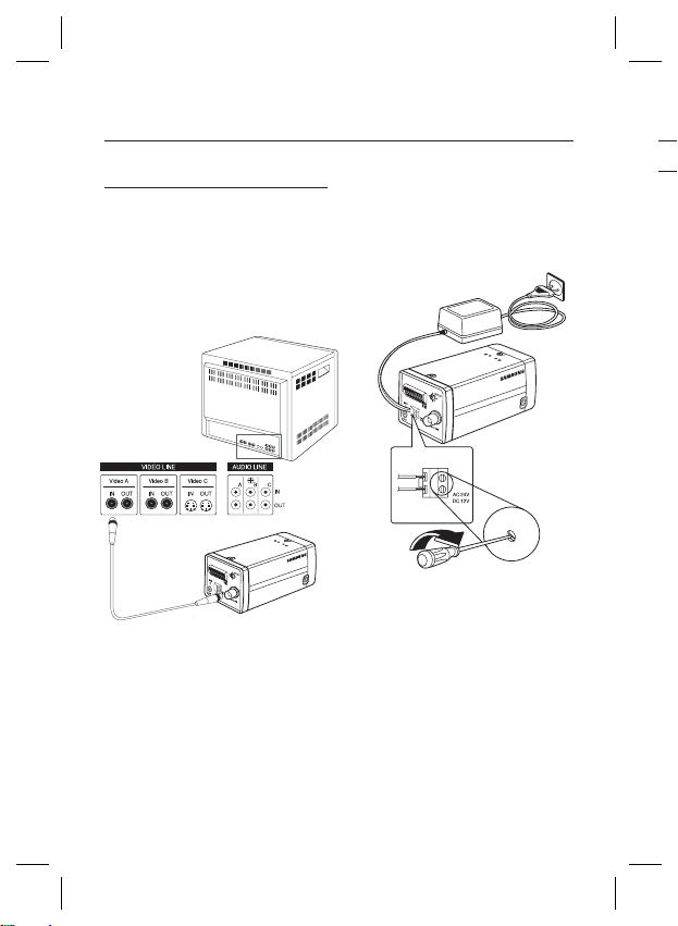
CONNECTING CABLES AND
CHECKING OPERATION
①
Connect one end of the BNC cable to the
VIDEO OUT Port on the rear of the camera.
② Connect another end of the BNC cable to the
VIDEO IN Port on the monitor.
Video In Terminal of Monitor Rear
Surface
BNC cable
1
.
A
L
A
R
2
.
A
G
M
N
O
D
3
U
.
T
G
N
5
.
D
S
4
.
H
S
U
H
6
T
U
.
T
S
T
E
T
H
R
E
U
(
S
R
7
T
1
(
.
T
S
)
5
E
O
V
R
)
(
O
S
8
U
2
.
)
T
D
A
Y
/
N
I
G
H
T
I
N
1
2
3
4
5
6
7
8
③
Finally connect the power adapter to the
camera. You can connect 2 lines of the power
adapter to the camera using the Slot Head
screwdriver as shown in the picture.
(GND: cable with the white stripe line)
1
.
A
L
A
R
2
.
A
G
M
N
O
D
3
U
.
T
G
N
5
.
D
S
4
.
H
S
U
H
6
T
U
.
T
S
T
E
T
H
R
E
U
(S
R
7
T
1
(
.
T
S
)
5
E
O
V
R
)
(S
O
8
U
2
.
)
T
D
A
Y
/
N
I
G
H
T
I
N
1 2
3 4
5 6
7
8
USI
•
•
•
•
•
E
B
sa
R
R
U
P
O
e
U
P
O
re
Video Out Terminal
12 – DIGITAL COLOR CAMERA
Note :
Connect any power source of AC 24V and DC 12V
–
irrespective of polarity.
Page 13
How to use OSD Menu
USING ICONS IN THE MENU
(EXIT)
•
Exits the menu setting.
Before you exits the menu setting, select SAVE to
save your settings, or select QUIT to cancel.
(RET)
•
Returns to the previous menu.
(SAVE)
•
Used to save your settings of MASK AREA,
PRIVACY ZONE and more.
Once you save your settings, they will remain
even if you select QUIT in the menu.
(DEL)
•
Used to deletes your settings of MASK AREA,
PRIVACY ZONE and more.
Once you delete your settings, they will not be
restored even if you select QUIT in the menu.
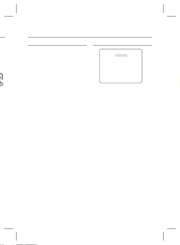
MAIN MENU
ÃÃMAIN MENUÃÃ
PROFILE
CAMERA SET
INTELLIGENCE
PRIVACY ZONE
OTHER SET
COMMUNICATION
SYSTEM INFO
PROFILE
•
You can set a mode according to the camera
installation conditions.
CAMERA SET
•
Confi gure Camera related functions and data.
INTELLIGENCE
•
You can confi gure the settings of motion
detection, tracking and more.
PRIVACY ZONE
•
You can confi gure the privacy related settings.
OTHER SET
•
You can confi gure for Factory Defaults, and more.
COMMUNICATION
•
Confi gures the settings regarding the RS-485
communication.
SYSTEM INFO.
•
Displays the system information including the
camera version and communication settings.
English – 13
Page 14
How to use OSD Menu
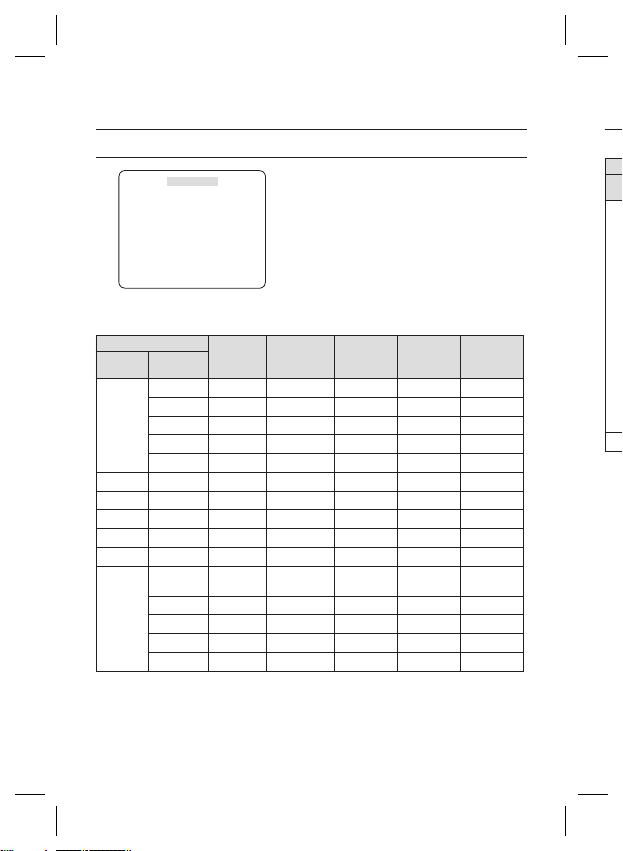
PROFILE
e
PROFILE
f
STANDARD
Ã
ITS
BACKLIGHT
DAY/NIGHT
GAMING
CUSTOM
In the PROFILE menu, you can confi gure the following camera settings at once.
Pr
M
W
CAMERA SET Menu
Previous
Menu
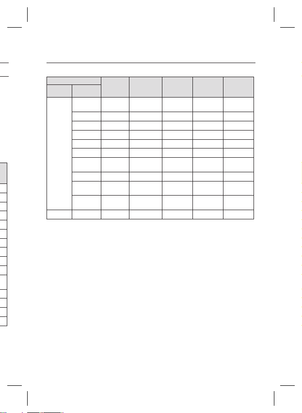
IRIS ALC ALC ALC ALC ALC
MOTION (F.FAST)--- (F.FAST)--- NORM (F.FAST)--- SLOW
DNR MID MID MID MID MID
SHUTTER OFF AUTO1/250 OFF OFF OFF
SENS-UP AUTOx4 AUTOx2 AUTOx4 AUTOx4 AUTOx4
XDR MID MID MID MID MID
DAY/
NIGHT
STANDARD ITS BACKLIGHT DAY/NIGHT GAMING
Sub-menus
ALC -- ---
LENS DC DC DC DC DC
LEVEL 0 0 0 0 0
BACKLIGHT OFF OFF BLC OFF OFF
AUTO AUTO DAY AUTO DAY
NIGHT - - - - -
BURST OFF ON OFF OFF OFF
EXT -- ---
BURST OFF ON OFF OFF OFF
14 – DIGITAL COLOR CAMERA
D
IT
❖
It w
B
❖
It w
D
❖
It w
G
❖
It w
Page 15
How to use OSD Menu
CAMERA SET Menu
Previous
Menu
WHITE
BAL
DETAIL 2 2 2 2 2
ITS
❖
STANDARD ITS BACKLIGHT DAY/NIGHT GAMING
Sub-menus
DAY DAY/NIGHT DAY DAY/NIGHT DAY
DAY -- ---
MODE ATW2 ATW1 ATW1 ATW1 ATW1
RED00 000
BLUE 0 0 0 0 0
NIGHT - - - - -
User setting
BRIGHTNESS
allowed
MODE OFF ATW2 OFF ATW2 OFF
User setting
RED
allowed
User setting
BLUE
allowed
User setting
MID
allowed
User setting
0
allowed
User setting
0
allowed
MID
0
0
User setting
allowed
User setting
allowed
User setting
allowed
It will be set automatically so you can easily check the traffi c conditions.
BACKLIGHT
❖
It will be set automatically so you can distinguish the object from the background in a severe backlighting scene.
DAY/NIGHT
❖
It will be set automatically so it optimizes to the day or night conditions, respectively.
GAMING
❖
It will be set automatically to help you take a picture in a regular indoor lighting condition.
English – 15
Page 16
How to use OSD Menu
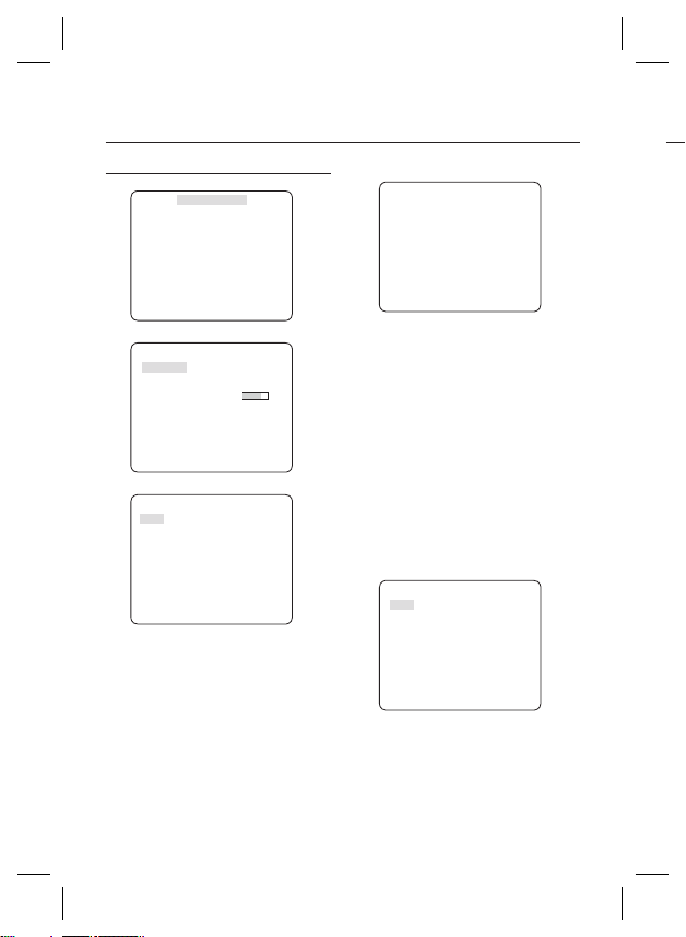
CAMERA ID [OFF, ON]
CAMERA SETUP
eCAMERA SETf
CAMERA ID OFF
IRIS ALC
MOTION (F.FAST)--DNR MID
SHUTTER OFF
SENS-UP AUTO X4
FLICKERLESS (OFF)--XDR MID
DAY/NIGHT AUTO
WHITE BAL
DIGITAL ZOOM
DETAIL [2]
V-SYNC INT
AGC COLOR SUP
REVERSE OFF
POSI/NEGA +
PIP OFF
DIS OFF
Setup the general functions of zoom camera module.
cdef
Use the
d
c
OFF
LOW
d
c
switch to select a menu item.
❖
CAMERA ID
ABCDEFGHIJKLMNOPQRSTUVWXYZ0
123456789 :?-+*()/
SP
ffee
SP LOCATION
..........................
...........................
The CAMERA ID menu is used for you to assign
a unique name to a camera. If you press the
SETUP switch with the CAMERA ID menu
selected, you will see the appropriate screen.
You can enter up to 54 alphanumeric or
special characters for the CAMERA ID. Select
LOCATION and press the SETUP switch to
move the display position of the CAMERA ID.
IRIS [ALC, ELC]
❖
The IRIS menu is used if you want to adjust the
intensity of radiation incoming to the camera.
ALC (Automatic Light Control)
•
① If you press the SETUP switch with an ALC-
based sub menu selected, you will see the
appropriate screen.
ALC
LENS DC
LEVEL [00]----I---BACKLIGHT OFF
The LENS menu is used if you select a type of
the AI lens.
For normal operation, you must select DC for a
DC-type lens, and select VIDEO for a VIDEOtype lens.
②
EL①•
16 – DIGITAL COLOR CAMERA
Page 17
How to use OSD Menu
The LEVEL menu is used to adjust the
overall brightness, where “+” will increase the
brightness and “–” will decrease it.
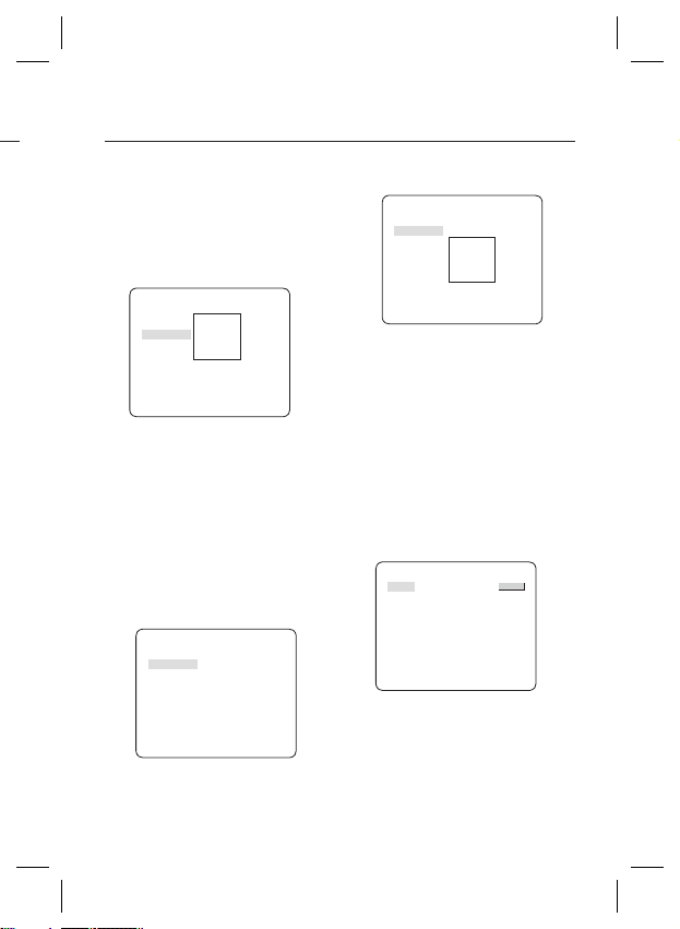
② If you set the BACKLIGHT option to BLC,
you will see a menu where you can set the
BLC area.
you can set the desired BLC zone by defi ning
the size and location.
ALC
LENS DC
LEVEL [00]----I---BACKLIGHT BLC
AREA USER
<SIZE>
<LOCATION>
If you use an ordinary camera in a scene
with an intensive backlight, the object will be
displayed dark on the monitor affected by the
backlight. To solve this problem, you can use
the BLC(Back Light Compensation) function
to improve the sharpness of the image in
such a high contrast scene.
ELC (Electronic Light Control)
•
① If you press the SETUP switch when the ELC
submenu is selected, the corresponding screen
appears. You can make the ELC (Electronic Light
Control) function active or not.
ELC
LEVEL [00]----I---BACKLIGHT OFF
② In similar to ALC setting, you can specify the
BLC area.
ELC
LEVEL [00]----I---BACKLIGHT BLC
AREA USER
<SIZE>
<LOCATION>
AGC
❖
[OFF, VERY LOW, LOW, MID, HIGH, VERY
HIGH, USER, FIX]
The AGC (Auto Gain Control) menu is used to
set the AGC level of the camera. When the AGC
is active, the camera automatically increases the
sensitivity by amplifying the Video signal when
the strength of the signal falls below the normal
value.
If OFF or FIX mode is selected in the SENS-UP
menu, you can specify the AGC level.
If you press the SETUP switch with a USER
sub menu selected, you will see the appropriate
screen.
AGC USER
LEVEL [16]
e of
In USER mode, you can break down the level in
16 steps from VERY LOW to VERY HIGH to your
preference.
English – 17
Page 18
How to use OSD Menu
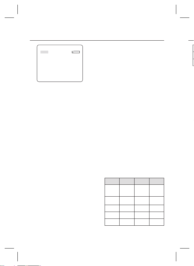
SHUTTER
AGC FIX
LEVEL [01]
If you press the SETUP switch with a FIX sub
menu selected, you will see the appropriate screen.
As a fi xed value of the AGC gain is used in FIX
mode, you can select one of the 16 detailed levels
from VERY LOW to VERY HIGH before fi xing it.
Note :
If the DAY/NIGHT menu of the CAMERA SET is set to
–
AUTO, the AGC menu will be deactivated.
If FLICKERLESS is set to ON, the AGC FIX mode will be
–
disabled.
MOTION
❖
Note :
–
DNR
❖
[S.SLOW, SLOW, NORM, FAST, F.FAST]
The MOTION menu is used to adjust the strength
of the AGC level for a control of the camera motion.
This is available only if the SENS-UP menu is set
to AUTO.
You can select one from S.SLOW, SLOW, NORM,
FAST and F.FAST for the AGC level.
If you monitor a fast moving object in a low contrast
scene, select F.FAST while select S.SLOW for a
hardly moving object in the same lighting condition.
If the DAY/NIGHT menu of the CAMERA SET is set to
AUTO, the MOTION menu will be deactivated.
[OFF,LOW,MID,HIGH, USER(1~16)]
You can confi gure the DNR (Digital Noise
Reduction) related settings.
Reduces the noise on the screen.
This is especially useful for a severely distorted screen.
You can set the level if you set DNR to USER.
❖
[OFF, AUTO 1/100(PAL:1/120), AUTO 1/250,
AUTO 1/500, AUTO 1/1000, AUTO 1/2000, AUTO
1/4000, AUTO 1/10K , 1/100(PAL:1/120), 1/250,
1/500, 1/1000, 1/2000, 1/4000, 1/10K , EXT]
The SHUTTER menu is used to set the fi xed
high-speed electronic shutter, auto high speed
electronic shutter and external high speed
electronic shutter(EXT).
You can select one of 7 options from 1/100(PAL:1/120)
to 1/10K for the fi xed high speed electronic shutter,
which is mostly used for imaging a fast moving object.
The auto high speed electronic shutter operates
as the fi xed high speed shutter in a high contrast
scene but automatically focuses the target if the
iris opens fully in a low contrast scene like in ELC
mode. When it gets brighter back, the mode will
switch to the fi xed high speed electronic shutter
mode.
However, the auto high speed shutter operates
properly only in a camera featuring a DC or VIDEO
lens.
In external high speed electronic shutter (EXT)
mode, you can select one of 8 modes from OFF
through 1/100(PAL:1/120) to 1/10K for the high
speed electronic shutter. It works as the high
speed electronic shutter. You can select an
option using SHUTTER(S0), SHUTTER(S1) and
SHUTTER(S2) on the rear.
Connect each of the terminals to GND.
See the below table for the operation.
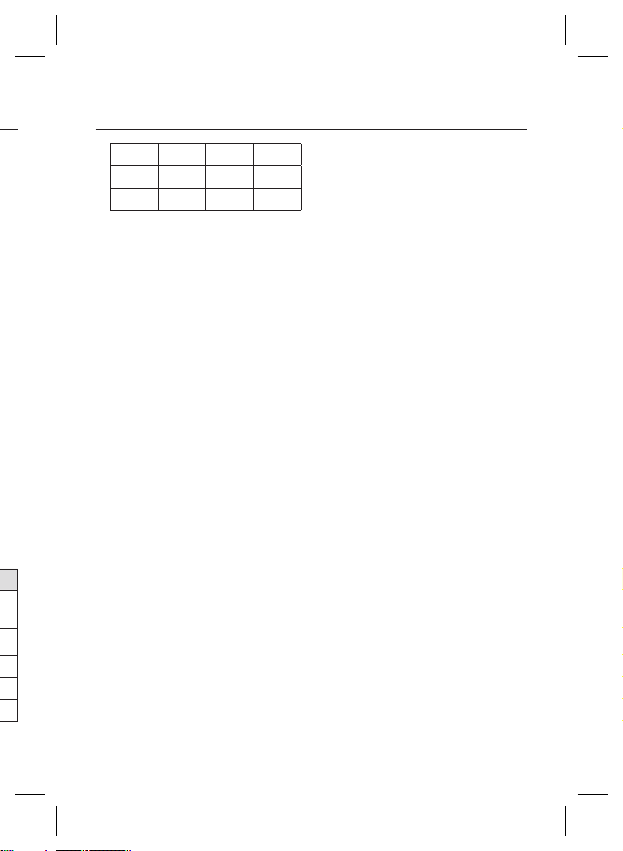
SHUTTER(S0) SHUTTER(S1) SHUTTER(S2)
OFF
(NTSC: 1/60,
OFF OFF OFF
PAL:1/50)
1/100
(PAL:1/120)
ON OFF OFF
1/250 OFF ON OFF
1/500 ON ON OFF
1/1000 OFF OFF ON
No
–
–
–
–
S
❖
[O
X
X
X
X
F
F
A
d
e
b
m
No
–
–
–
–
18 – DIGITAL COLOR CAMERA
Page 19
How to use OSD Menu
FLICKERLESS [OFF, ON]
1/2000 ON OFF ON
1/4000 OFF ON ON
1/10K ON ON ON
Note :
If IRIS mode is set to ELC, the SHUTTER menu will be
–
deactivated as you adjust the brightness using the
electronic shutter.
If the SENS-UP function is set to AUTO, only items of
–
OFF and AUTO are available in the SHUTTER menu.
If the SENS-UP mode is set to FIX, the SHUTTER menu
–
will be deactivated.
If the FLICKERLESS function is set to ON, the SHUTTER menu
e
h
–
will be deactivated.
SENS-UP
❖
[OFF, AUTO X2, AUTO X4, AUTO X6, AUTO
X8, AUTO X12, AUTO X16, AUTO X24, AUTO
X32, AUTO X48, AUTO X64, AUTO X96, AUTO
X128, AUTO X256, AUTO X512, FIX X2, FIX
X4, FIX X6, FIX X8, FIX X12, FIX X16, FIX X24,
FIX X32, FIX X48, FIX X64, FIX X96, FIX X128,
FIX X256, FIX X512]
Automatically detects the ambient level of
darkness in the dark or low contrast scene to
extend the accumulated time, keeping the image
bright and sharp; It can be also used as FIX
mode.
Note :
If the SHUTTER option is set to fi xed electronic shutter or
–
EXT mode, the SENS-UP menu will be deactivated.
If FLICKERLESS is set to ON, the FIX mode of the SENS-
–
UP menu will be disabled.
If the IRIS menu is set to ELC, the electronic shutter will
–
control the brightness so the SENS-UP function can not
be set to FIX mode, but to OFF or AUTO mode.
If the SHUTTER menu is set to AUTO, the SENS-UP
–
menu can be set to either OFF or AUTO mode.
❖
If set to ON, the shutter speed will be fi xed to
1/100(PAL:1/120) second. This will prevent possible screen
distortion due to a mismatch between the vertical sync
frequency and the blinking frequency of the lighting.
Note :
If the IRIS function is set to ELC, the Flickerless menu will
–
be deactivated. If the SHUTTER menu is set to AUTO, FIX
or EXT mode, the Flickerless menu will be deactivated.
If the SENS-UP function is set to FIX mode, the Flickerless
–
menu will be deactivated.
If AGC is set to FIX mode, the FLICKERLESS function will
–
be disabled.
XDR (eXtended Dynamic Range)
❖
[OFF, LOW, MID, HIGH]
Actively controls the gamma compensation in the
way it operates the ambient luminance contrast
in a certain pixel unit to determine the optimal
visibility.
Select one from OFF, LOW, MID and HIGH.
Closing to HIGH will increase the compensation
level.
DAY/NIGHT
❖
DAY
•
If set to DAY, it will be fi xed to DAY mode
regardless of the ambient conditions.
NIGHT
•
If set to NIGHT, it will be fi xed to Black-and-White
mode regardless of the ambient conditions.
If you press the SETUP switch with a NIGHT sub
menu selected, you will see a menu where you can
set Burst to OFF/ON.
If BURST is set to ON, the Burst signal will output
together with the black-and-white composite video
signal. If BURST is set to OFF, the Burst signal does
not output.
You can set the BURST option to OFF/ON, or
select to output the Burst signal in NIGHT mode.
[DAY,NIGHT,AUTO,EXT]
English – 19
Page 20
How to use OSD Menu
AUTO
•
The camera will automatically switch between
DAY and NIGHT mode, according to the lighting
condition.
If you press the SETUP switch with an AUTObased sub menu selected, you will see the
appropriate screen.
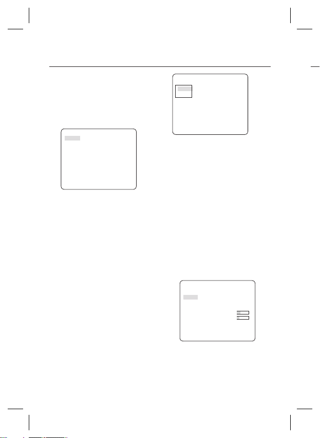
AUTO
BURST OFF
DAYÆNIGHT
BRIGHTNESS MID
DWELL TIME 2SEC
NIGHTÆDAY
BRIGHTNESS MID
DWELL TIME 5SEC
MASK AREA 1 2
You can set the BURST option to OFF/ON, or
select to output the Burst signal in NIGHT mode.
You can select from LOW, MID and HIGH for
the brightness of DAYÆNIGHT, which is a
brightness level in switching from the color fi lter
to Black-and-White. Closing to LOW from HIGH
will switch the fi lter in a low contrast scene.
The DWELL TIME of DAYÆNIGHT is a time
required to determine the need for switching the
fi l t e r .
You can select from LOW, MID and HIGH for
the brightness of NIGHTÆDAY, which is a
brightness level in switching from the Black-andWhite fi lter to color. Closing to LOW from HIGH
will switch the fi lter in a low contrast scene.
The DWELL TIME of NIGHTÆDAY is a time
required to determine the need for switching the
fi l t e r .
The MASK menu is used to prevent a fi lter
switch error or inability of determining the switch
in existence of a high spot light source at night.
If you press the SETUP switch in item 1 or 2 of
the MASK menu, you will see a menu where you
can specify an area to mask.
MASK AREA
<SIZE>
<LOCATION>
You can specify Mask 1 and 2 simultaneously.
The mask is used only for determining the fi lter
switch and any excessive bright area at night will
be masked.
Note :
–
If BACKLIGHT is set to BLC, the MASK AREA function will
be deactivated.
EXT
•
This enables an auto switch between DAY and
NIGHT mode using the interface with the external
sensor.
WHITE BAL [DAY/NIGHT]
❖
If you want to adjust the color scheme, use the
WHITE BALANCE function.
DAY
•
In DAY mode, you can set the color values of
RED and BLUE. The screen will be displayed in
colors according to your settings.
WHITE BAL
DAY/NIGHT DAY
MODE AWC
RED [00]----I--- BLUE [00]----I--- R-GAIN [0248]
B-GAIN [0247]
Note :
You can set the values of R-GAIN and B-GAIN only in
–
AWC mode.
NI
•
U
b
lu
If
b
if
D
In
B
d
No
–
–
Fo
–
5
•
•
•
•
•
20 – DIGITAL COLOR CAMERA
Page 21

How to use OSD Menu
NIGHT
•
Use the NIGHT mode if you want to set the white
balance differently according to the ambient
luminance.
If the NIGHT mode is set to OFF, the white
balance will always operate as set in DAY mode;
if not to OFF, the camera will switch to as set in
DAY/NIGHT mode according to the brightness.
In NIGHT mode, you can set the values of RED,
BLUE and BRIGHTNESS. The screen will be
displayed in colors according to your settings.
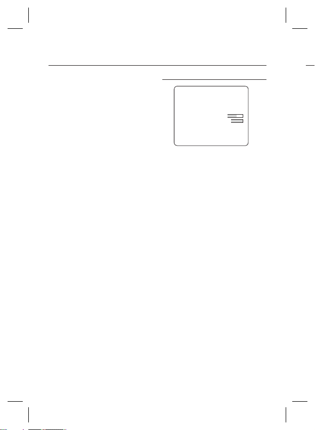
WHITE BAL
DAY/NIGHT NIGHT
BRIGHTNESS MID
will
MODE AWC
RED [00]----I--- BLUE [00]----I--- R-GAIN [0248]
B-GAIN [0247]
Note :
–
You can set the values of R-GAIN and B-GAIN only in
AWC mode.
If AGC is set to OFF or FIX, you can not access the
–
NIGHT menu.
For adjusting the white balance, the following
–
5 modes are provided:
ATW1(Auto Tracing White Balance mode
•
1): The camera can automatically adjust the
color temperature in real time, according to
the ambient conditions. The color temperature
ranges from approx. 2500K to 9300K.
ATW2: The color temperature ranges from
•
approx. 2,000K to 10,000K.
AWC ( Auto White Balance Control): If you
•
press the SETUP switch in the appropriate item
position, Auto White Balance will perform once.
3200K : Set color temperature to 3200K
•
5600K : Set color temperature to 5600K
•
RED : Adjusts the strength of the red color.
–
BLUE : Adjusts the strength of the blue color.
–
R-GAIN/B-GAIN : Enables you to set the current
–
color temperature manually.
BRIGHTNESS : Select a brightness level in
–
switching from setting in DAY mode to setting in
NIGHT mode.
DIGITAL ZOOM [ON/OFF]
❖
You can set the digital zoom factor and position.
If you press the SETUP switch with the DIGITAL
ZOOM function set to ON, you will see the
appropriate screen.
When the zoom factor and position are defi ned,
the digital zoom function will operate.
DIGITAL ZOOM
RATIO [X1.0]
< LOCATION >
-
LOCATION : If you press the SETUP switch in the
condition where the image is enlarged as much as the
ratio setting, you can watch an invisible area of the
effective screen as well using the
Note :
–
If the digital zoom factor is set to larger than 1x, the FENCE
function will be deactivated.
The DIGITAL ZOOM function enlarges the pixel itself, which can
cause deterioration of the quality.
DETAIL [0~3]
❖
cdef
switch.
Controls the horizontal or vertical distinction.
English – 21
Page 22
How to use OSD Menu
V-SYNC [INT, LINE]
❖
Select the vertical sync mode for INT or LINE.
If you select INT, the camera will use the internal
synchronization.
If selecting LINE, the camera will use the external
power source frequency for the synchronization.
You can adjust the LL-PHASE.
Note :
Use of DC 12V will fi x V-SYNC to INT, which can not be
–
changed.
AGC COLOR SUP [LOW , MID, HIGH]
❖
Adjust the color scheme according to the AGC
value.
REVERSE [OFF, H, V, H/V]
❖
Mirrors video signals horizontally, vertically, or
both.
POSI/NEGA [+, -]
❖
Output as it is or mirror the video brightness
signal.
PIP [OFF, ON]
❖
Displays a sub image together with the main
image on the same screen using the Picture In
Picture function.
Note :
If more than one privacy zone is set and the PRIVACY
–
SET is set to ON, the PIP function will be deactivated.
If the INTELLIGENCE function is set to FENCE mode, the
–
PIP menu will be deactivated.
DIS [OFF, ON]
❖
Digital Image Stabilization will set the anti-shake
compensation.
Note :
If you set DIS to ON, the compensation area will be
–
enlarged as set in the digital zoom factor.
If you set the digital zoom factor to greater than the
enlarged zoom factor for the compensation, the DIS
function will be deactivated.
INTELLIGENCE
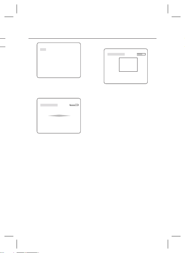
eINTELLIGENCEf
MOTION OFF
ADVANCED OFF
MASK AREA
DISPLAY ON
SENSITIVITY [4]
RESOLUTION [5]
ALARM OUT
You can set the motion detection and tracking in the
INTELLIGENCE menu.
MOTION
❖
•
TRACKING
Detects and tracks a moving object.
•
DETECTION
Detects a moving object.
Note :
If it is set to DETECTION, you can not set such functions as
–
FIXED/MOVED and FENCE in the ADVANCED menu.
ADVANCED
❖
Detects a motion of an object and displays an
image of any moving object before tracking the
moving route.
FENCE
•
This is to detect if a moving object passes
through the specifi ed LINE or AREA.
In a condition where a moving object is detected
in an analysis of the previous and current frames
whose movement overlaps a certain area, the
system displays “PASS” if the object’s center line
passes through the line while it displays “ENTER”
or “EXIT” if the center point passes through the
area.
[OFF,TRACKING,DETECTION]
[OFF, FIXED/MOVED, FENCE]
1 2 3 4
Yo
LI
- H
①
②
③
④
22 – DIGITAL COLOR CAMERA
Page 23
How to use OSD Menu
FENCE
LINE OFF
AREA OFF
You can set the position and detection direction of the
LINE, and the size and position of the AREA.
- How to set the line
LINE
PIXEL LEVEL [4]
<POINT>
DIRECTION §¨
① If you press the SETUP switch with the LINE
option set to ON, you can specify the position
and detection direction of the line.
② If you change the PIXEL LEVEL for setting
the position, specify the pixel that moves by a
single pressure of the
③
In <POINT>, you can specify the fi rst position of
the line by pressing the SETUP switch once, and
the second position by pressing the switch again.
Use the
position.
Set each position of the two points and press the
SETUP switch to complete the positioning.
④
If you change the DIRECTION, you can specify
the detection direction. The detection direction
based on the defi ned two points will be
displayed on the screen.
cdef
cdef
switch.
switch to specify the
- How to set the area
AREA
PIXEL LEVEL [4]
<SIZE>
<LOCATION>
① If you press the SETUP switch with the AREA
option set to ON, you can specify the position
and size of the area.
② If you change the PIXEL LEVEL for setting
the position, specify the pixel that moves by a
single pressure of the
③
In <SIZE>, press the SETUP switch and use
cdef
the
Press the SETUP switch again to complete the
sizing.
④
In <LOCATION>, press the SETUP switch and
use the
Press the SETUP switch again to complete
the positioning.
Note :
If you set the LINE of the FENCE to ON, PRIVACY 12 will
–
not be available.
Functions of FENCE, PIP, DIS and DIGITAL ZOOM (if the
digital zoom factor is set to larger than 1x) can not be
used simultaneously.
In the boundary of the defi ned AREA and LINE, a FENCE
–
detection error may occur if two or more moving objects
overlap with each other or one object separates in
multiple directions.
FIXED/MOVED
•
If an object on the screen suddenly disappears or
an object comes out of nowhere and stays for a
certain time, the area will be displayed.
A detection (FIXED/MOVED) error may occur if :
- multiple motions occur continuously in random
directions
- a fi xed object moves in one position continuously
- a second object screens the fi rst moving object
cdef
switch to adjust the size.
cdef
switch to specify the position.
switch.
English – 23
Page 24
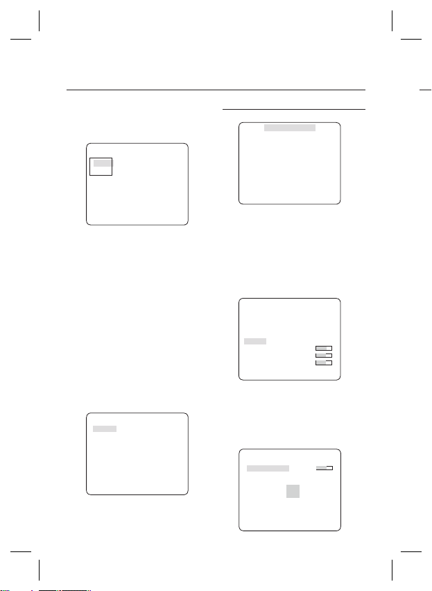
How to use OSD Menu
MASK AREA [1~4]
❖
Specify a detection exception area to mask.
Select a mask number and specify the size and
position.
MASK AREA
<SIZE>
<LOCATION>
DISPLAY [ON, OFF]
❖
With the DISPLAY option set to ON, a motion or
a set ADVANCED function will be displayed on
the screen, if detected.
SENSITIVITY [1~7]
❖
Set the sensitivity of the motion detection.
RESOLUTION [1~5]
❖
If setting it to high, the camera can detect even a
trivial movement of the target.
❖
ALARM OUT
If you set a desired menu item to ON, the camera
will sound an alert if it detect the appropriate
motion.
ALARM OUT
MOTION ON
FIXED/MOVED ON
FENCE
LINE ON
AREA
ENTER ON
EXIT ON
24 – DIGITAL COLOR CAMERA
PRIVACY ZONE SETUP
ePRIVACY ZONEf
1 2 3 4 5 6
7 8 9 10 11
PRIVACY SET ON
STYLE
The PRIVACY function will protect your privacy by
screening the privacy area that you have specifi ed
during monitoring. You can specify up to 12 privacy
zones.
If you set the PRIVACY SET to ON, your PRIVACY
ZONE settings will be applied.
You can change the style to adjust the mosaic size
and color of the PRIVACY ZONE.
ePRIVACY ZONEf
1 2 3 4 5 6
7 8 9 10 11
PRIVACY SET ON
STYLE COLOR
Y-LEVEL [128]
RED [128]
BLUE [128]
cdef
Use the
PRIVACY 1 through 12.
Select one from PRIVACY 1~12 and press the
SETUP switch to confi rm your setting. You can
specify a pixel that moves as you change the PIXEL
LEVEL to set the position.
switch to select one from
PRIVACY ZONE SET1
PIXEL LEVEL [4]
<POINT>
<POSITION>
MOSAIC1
-
①
12
②
-
①
②
No
12
–
–
Page 25

How to use OSD Menu
- How to set the point
You can set each position of the 4 points.
① If you press the SETUP switch in <POINT>,
you will see the points available in the
PRIVACY ZONE. Each time you press the
SETUP switch, the points available will move.
② Use the
of each point. Set each position of the four
points and press the SETUP switch to
complete the positioning.
- How to set the position
You can move the position of the overall area.
① By pressing the SETUP switch in
<POSITION>, you can move the overall
position of the privacy zone.
② Use the
position and press the SETUP switch to
confi rm it.
Note :
If more than one PRIVACY ZONE is specifi ed and the
–
PRIVACY SET is set to ON, the PIP function will be
deactivated.
If the 12th PRIVACY ZONE is specifi ed, the LINE function
–
of FENCE will be deactivated.
switch to set the position
cdef
cdef
switch to move the
OTHER SET
eOTHER SETf
LANGUAGE ENGLISH
FACTORY DEFAULTS
OSD COLOR BW
LANGUAGE
❖
You can slect a preferred language for the screen
display.
Select your language by using the left and right keys.
FACTORY DEFAULTS
❖
All the settings will be restored to the factory
default.
However, the settings of PROTOCOL, BAUD
RATE, ADDRESS and LANGUAGE will not be
restored to the default.
OSD COLOR [BW, R/G/B]
❖
You can set the OSD(On-screen Display) color to
COLOR or B/W.
English – 25
Page 26
How to use OSD Menu
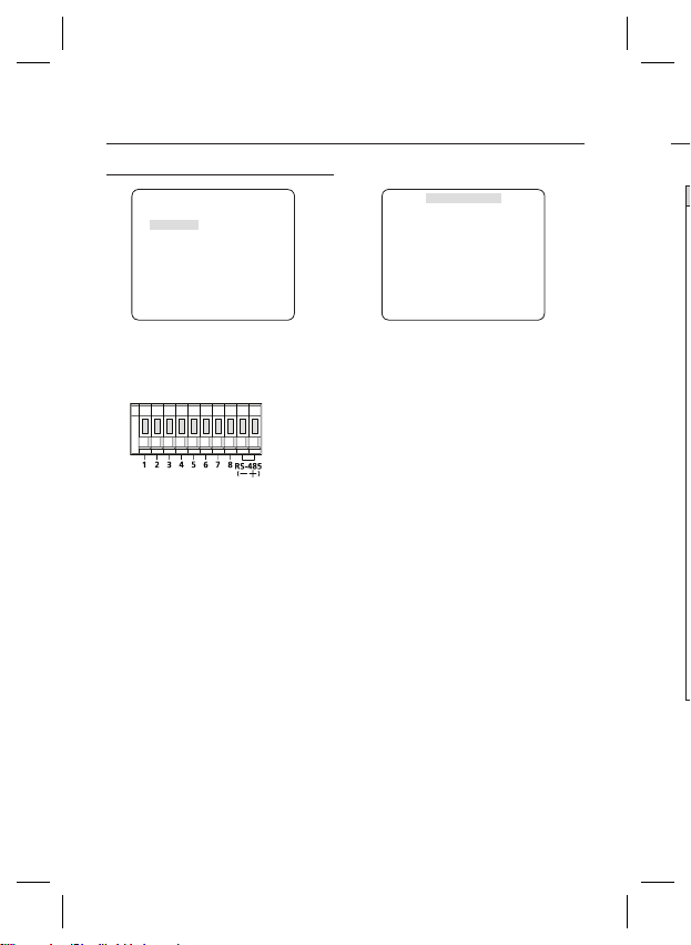
COMMUNICATION
eCOMMUNICATIONf
RS-485
PROTOCOL
BAUD RATE 9600
ADDRESS 0
The COMMUNICATION menu is used to confi gure
the settings regarding RS-485 communications.
Use the rear panel of the camera to connect to
RS-485.
[Camera I/O Connector]
cdef
Use the
baud rate and address (0~255) for communications.
PROTOCOL
❖
Select a communication protocol.
BAUD RATE
❖
Select a baud rate.
Note :
The baud rate differs, depending on the specifi ed
–
protocol.
ADDRESS
❖
You must specify a unique address for each
camera in the same RS-485 network.
To control a specifi c camera, you must match the
address of the camera with that of the DVR or the
controller.
SAMSUNG-E
switch to specify the protocol,
[0~255]
SYSTEM INFORMATION
eSYSTEM INFOf
TYPE 2_BOX_NOR_P
PROTOCOL
ADDRESS 1
COMM. TYPE RS-485,HALF
BAUD RATE
SERIAL NO.
000000000000000
CAMERA VER. v2.00_100501
You can view the system information including the
protocol, address, baud rate, serial number, camera
version, and EEP version.
In❖
SAMSUNG-E
9600
26 – DIGITAL COLOR CAMERA
Page 27

Initial Confi guration Table
❖
Camera Confi guration
•
CAMERA ID OFF
IRIS ALC
AGC VERY HIGH
MOTION (F.FAST)
DNR MID
SHUTTER OFF
SENS-UP
AUTO x4
FLICKERLESS (OFF)
XDR MID
DAY/NIGHT AUTO
DIGITAL ZOOM OFF
DETAIL [2]
AGC COLOR SUP MID
REVERSE OFF
POSI/NEGA +
PIP OFF
DIS OFF
V-SYNC INT
How to use OSD Menu
English – 27
Page 28
Specifi cations
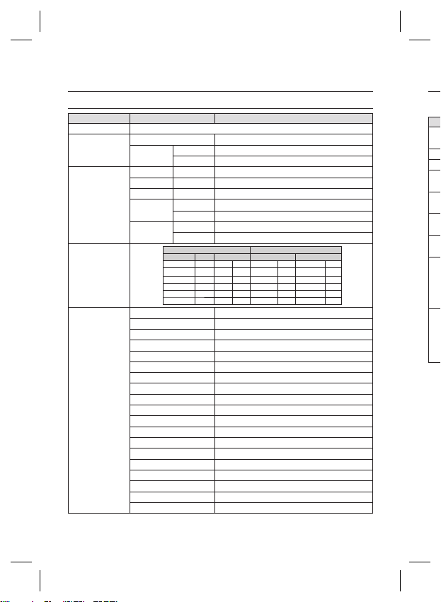
SPECIFICATIONS
Items Sub-items
Camera Type
Image
Scanning
Min. Scene
Illumination
Functions
Device 1/2” Exview-HAD IT CCD
Pixels
System Interlace
Scanning Line 525 lines
Frame 30frame/1sec
Horizontal
Frequency
Vertical
Frequency
Number of Privacy Zone 12 (Polygonal Method)
eXtended Dynamic Range(XDR) Off/On (Level Setting)
Digital Noise Reduction(DNR) Off/On (Adaptive 3D+2D)
Digital Image Stabilization(DIS)
Total 811 x 508
Effective 768 x 494
Internal Mode 15,734 Hz
Line-lock Mode 15,750 Hz
Internal Mode 59.94 Hz
Line-lock Mode 60 Hz
Sens-up F No. Level DAY NIGHT
OFF 1.2
OFF 1.2 30
512 times 1.2 50 IRE 0.00020 Lux 0.00002 Lux
512 times 1.2 15 IRE 0.00006 Lux 0.00001 Lux
Day/Night DAY/NIGHT/AUTO/EXT
Motion Detection OFF/Tracking/Detection
D-Zoom x1 ~ x16 (x0.1 STEP)
PIP Off/On
High Speed Shutter 1/60 ~ 1/10Ksec (OSD/External Control)
Flickerless Off/On
Sens-Up x2 ~ x512
BLC Off/On (Area Setting)
AGC Off/On (Max.Level Setting)
ELC Off/On ( ~ 1/200K sec)
Line Lock Off/On (Phase Control)
Camera ID Off/On (Max.54ea/2Line)
White Balance ATW1/ATW2/AWC/3200K/5600K
Intelligent Video Fixed/Moved, Fence
Etc. Function Detail, Reverse(H/V), Posi/Nega
SCB-4000N
CCTV Camera (DAY/NIGHT)
Condition Min. Scene illumination
0.10
Lux 0.010 Lux
IRE
50
0.06
IRE
IRE
0.03 Lux 0.003 LuxOFF 1.2 15
Lux 0.00001 Lux512 times 1.2 30 IRE 0.00012
Lux 0.006
Off/On
E
Lux
28 – DIGITAL COLOR CAMERA
Page 29
Specifi cations
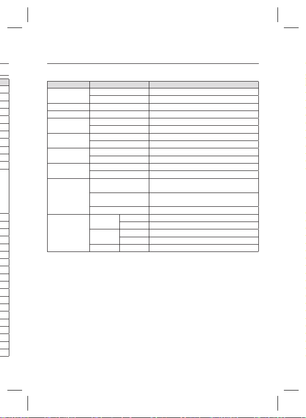
Items Sub-items
Resolution
Video Output
S/N Ratio
Lens
Alarm
Remote
Control
Environmental
Conditions
Power
Physical
Specifi cation
Lens Drive Type MANUAL/AI(VIDEO/DC)
Coaxitron (Data On Coax cable) Yes (with SCX-RD100)
Operating Temperature -10˚C ~ +50˚C
Power Requirement
Power Consumption
(With DC Lens)
LED Indicator Yes
Dimensions
(WxHxD)
Weight
Color Body Silver
Horizontal 600 TV Lines
Vertical 350 TV Lines
- VBS 1.0Vp-p, 75 Ω
S/N Ratio Approx. 52dB
Mount Type CS/C
Input N/A
Output 1 Output
RS-485 Yes (Multi Protocol, 8ea)
Humidity Less than 90%
Net 64(W) x 58(H) x 109.2(D) mm
Package 173(W) x 99(H) x 115(D) mm
Net 305g
Package 530g
SCB-4000N
AC24V ± 10%(60Hz ± 0.3Hz)
DC12V ± 10%
In normal operation : 2.3W
In switching the DAY/NIGHT fi lter : 3.0W
English – 29
Page 30
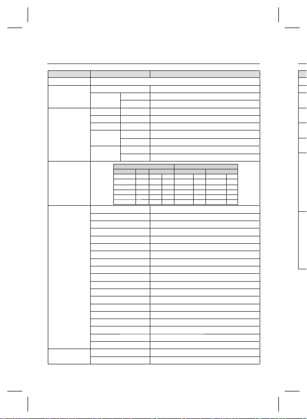
Specifi cations
Items Sub-items
Camera Type
Image
Scanning
Min. Scene
Illumination
Functions
Resolution
Device 1/2” Exview-HAD IT CCD
Pixels
System Interlace
Scanning Line 625 lines
Frame 25frame/1sec
Horizontal
Frequency
Vertical
Frequency
Number of Privacy Zone 12 (Polygonal Method)
eXtended Dynamic Range(XDR) Off/On (Level Setting)
Digital Noise Reduction(DNR) Off/On (Adaptive 3D+2D)
Digital Image Stabilization(DIS)
Total 795 x 596
Effective 752 x 582
Internal Mode 15,625 Hz
Line-lock Mode 15,625 Hz
Internal Mode 50 Hz
Line-lock Mode 50 Hz
Sens-up F No. Level DAY NIGHT
OFF 1.2
OFF 1.2 30
512 times 1.2 50 IRE 0.00020 Lux 0.00002 Lux
512 times 1.2 15 IRE 0.00006 Lux 0.00001 Lux
Day/Night DAY/NIGHT/AUTO/EXT
Motion Detection OFF/Tracking/Detection
D-Zoom Max. x16
PIP Off/On
High Speed Shutter 1/50 ~ 1/10Ksec (OSD/External Control)
Flickerless Off/On
Sens-Up x2 ~ x512
BLC Off/On (Area Setting)
AGC Off/On (Max.Level Setting)
ELC Off/On ( ~ 1/200K sec)
Line Lock Off/On (Phase Control)
Camera ID Off/On (Max.54ea/2Line)
White Balance ATW1/ATW2/AWC/3200K/5600K
Intelligent Video Fixed/Moved, Fence
Etc. Function Detail, Reverse(H/V), Posi/Nega
Horizontal 600 TV Lines
Vertical 350 TV Lines
SCB-4000P/SCB-4000PH
CCTV Camera (DAY/NIGHT)
Condition Min. Scene illumination
0.10
Lux 0.010 Lux
IRE
50
0.06
IRE
IRE
0.03 Lux 0.003 LuxOFF 1.2 15
Lux 0.00001 Lux512 times 1.2 30 IRE 0.00012
Lux 0.006
Off/On
E
Lux
30 – DIGITAL COLOR CAMERA
Page 31
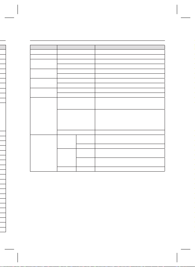
Items Sub-items
Video Output
S/N Ratio
Lens
Alarm
Remote
Control
Environmental
Conditions
Power
Physical
Specifi cation
Lens Drive Type MANUAL/AI(VIDEO/DC)
Coaxitron (Data On Coax cable) Yes (with SCX-RD100)
Operating Temperature -10˚C ~ +50˚C
Power Requirement
Power Consumption
(With DC Lens)
LED Indicator Yes
Dimensions
(WxHxD)
Weight
Color Body Silver
Specifi cations
- VBS 1.0Vp-p, 75 Ω
S/N Ratio Approx. 52dB
Mount Type CS/C
Input N/A
Output 1 Output
RS-485 Yes (Multi Protocol, 8ea)
Humidity Less than 90%
Net
Package 173(W) x 99(H) x 115(D) mm
Net
Package
SCB-4000P/SCB-4000PH
SCB-4000P : AC24V ± 10%(50Hz±0.3Hz)
DC12V ± 10%
SCB-4000PH : AC220V ± 10%(50Hz±0.3Hz)
In Normal operation :
SCB-4000P: 2.3W
SCB-4000PH : 3.5W
In switching the DAY/NIGHT fi lter :
SCB-4000P:2.9W
SCB-4000PH : 4.1W
SCB-4000P : 64(W) x 58(H) x 109.2(D) mm
SCB-4000PH: 64(W) x 58(H) x 129.2(D) mm
SCB-4000P : Approx. 305g
SCB-4000PH : Approx. 395g
SCB-4000P : Approx. 530g
SCB-4000PH: Approx. 620g
English – 31
Page 32

SALES NETWORK
SAMSUNG TECHWIN CO., LTD.
Samsungtechwin R&D Center, 701, Sampyeong-dong, Bundang-gu, Seongnam-si, Gyeonggi-do, Korea, 463-400
TEL : +82-70-7147-8740~60 FAX : +82-31-8018-3745
SAMSUNG TECHWIN AMERICA Inc.
1480 Charles Willard St, Carson, CA 90746, UNITED STATES
Tol Free : +1-877-213-1222 FAX : +1-310-632-2195
www.samsungcctvusa.com
www.samsungsecurity.com
www.samsungtechwin.com
SAMSUNG TECHWIN EUROPE LTD.
Samsung House, 1000 Hillswood Drive, Hillswood Business
Park Chertsey, Surrey, UNITED KINGDOM KT16 OPS
TEL : +44-1932-45-5300 FAX : +44-1932-45-5325
P/NO. : Z6806-1434-01A
 Loading...