

Page 1
PlasmaTV
ChassisF83A
ModelCodePS43D490A1XZN
MANUAL
SERVICE
PlasmaTV
1.Precaution
2.ProductSpecication
3.Disassembly&Reassembly
4.Troubleshooting
5.WiringDiagram
PS43D490A1
Contents
RefertotheservicemanualintheGSPN(seetherearcover)formoreinformation.
Page 2

Contents
Contents
1.Precaution........................................................................................................................................1−1
1.1.SafetyPrecautions...................................................................................................................1−1
1.2.ServicingPrecautions...............................................................................................................1−3
1.3.StaticElectricityPrecautions......................................................................................................1−4
1.4.InstallationPrecautions.............................................................................................................1−5
2.ProductSpecication.........................................................................................................................2−1
2.1.ProductFeature.......................................................................................................................2−1
2.2.SpecicationsAnalysis.............................................................................................................2−3
2.3.Accessories............................................................................................................................2−5
2.3.1.SuppliedAccessories...................................................................................................2−5
2.3.2.SoldSeparately...........................................................................................................2−6
3.Disassembly&Reassembly................................................................................................................3−1
3.1.OverallDisassembly&Reassembly............................................................................................3−1
3.2.MethodforDisassemblyofFunctionAssy....................................................................................3−5
4.Troubleshooting................................................................................................................................4−1
4.1.CheckpointsbyErrorMode.......................................................................................................4−1
4.1.1.FirstChecklistforTroubleshooting.................................................................................4−1
4.1.2.CheckpointsbyErrorMode...........................................................................................4−2
4.1.3.FaultsandCorrectiveActions........................................................................................4−8
4.1.4.OperatingLogicLED...................................................................................................4−10
4.1.5.AdjustFunctionKeySensitivity.....................................................................................4−11
4.1.6.FunctionAssyPinMap................................................................................................4−14
4.1.7.AdjustSMPSV oltagewhenchangeSMPS.......................................................................4−15
4.2.FactoryModeAdjustments........................................................................................................4−16
4.2.1.EnteringFactoryMode.................................................................................................4−16
4.2.2.FactoryData...............................................................................................................4−17
4.3.ServiceAdjustment..................................................................................................................4−39
4.4.SoftwareUpgrade....................................................................................................................4−42
5.WiringDiagram................................................................................................................................5−1
5.1.OverallWiring........................................................................................................................5−1
5.1.1.PinConnection...........................................................................................................5−4
iCopyright©1995-2011SAMSUNG.Allrightsreserved.
Page 3
1.Precaution
DEVICE
UNDER
TEST
LEAKAGE
CURREN T
TESTER
TES T ALL
EXPOSED ME TAL
SUR FACES
2-WIRE CORD
ALSO TES T WITH
PLUG REVERSED
(USING AC
ADAPTER PLUG
AS REQU IRED)
EARTH
GRO UND
( R E A D I N G
SHOULD NOT BE
ABOVE 0.5mA)
1.Precaution
Toavoidpossibledamage,electricshocksorexposuretoradiation,followtheinstructionsbelowwithregardtosafety,
installation,serviceandESD.
1.1.SafetyPrecautions
1)Makesureallprotectivedevicesareproperlyinstalledincludingnon-metallichandlesandcompartmentcoverswhen
installingorre-installingthechassisorchassisassemblies.
2)Makesurethatnogapsexistbetweenthecabinetsforchildrentoinserttheirngersintopreventchildrenfrom
receivingelectricshocks.GapsmentionedaboveincludeventilationholesofatoogreatmagnitudebetweenthePDP
moduleandthecabinetmask,andtheimproperinstallationoftherearcabinet.
Errorsmayoccurwhentheresistanceisbelow1.0MΩorover5.2MΩ.Inthesecases,makesurethatthedeviceis
repairedbeforesendingitbacktothecustomer.
3)CheckforElectricityLeakage(ACLeakageT est)
WARNING
Donotuseaninsulatedtransformerforcheckingtheleakage.Useonlythosecurrentleakagetestersormirroring
systemsthatcomplywithANSIC101.1andtheUnderwriterLaboratory’sspecications(UL1410,59.7).
Figure1.1ACLeakageT est
4)Ahighvoltageismaintainedwithinthespeciedlimitsusingsafetyparts,calibrationandtolerances.Whenvoltage
exceedsthespeciedlimits,checkeachspecialpart.
5)W arningforEngineeringChanges:
Nevermakeanychangesoradditionstothecircuitdesignortheinternalpartforthisproduct.
Ex:Donotaddanyaudioorvideoaccessoryconnectors.Thismightcausephysicaldamage.
Furthermore,anychangesoradditionstotheoriginaldesign/engineeringwillinvalidatethewarranty.
6)W arning-HotChassis:
SomeTVchassisaredirectlyconnectedtooneendoftheACpowercordforelectricalreasons.Withoutinsulated
transformers,theproductcanonlyberepairedsafelywhenthechassisisconnectedtotheearthedendoftheAC
powersource.
TomakesuretheACpowercordisproperlyconnected,followtheinstructionsbelow.Usethevoltmetertomeasurethe
voltagebetweenthechassisandtheearthedground.Ifthemeasurementisover1.0V ,unplugtheACpowercordand
changethepolaritybeforereinsertingit.Measurethevoltagebetweenthechassisandthegroundagain.
Copyright©1995-2011SAMSUNG.Allrightsreserved.1-1
Page 4

1.Precaution
7)SomeTVchassisareshippedwithanadditionalsecondarygroundingsystem.Thesecondarysystemisadjacentto
theACpowerline.Thesetwogroundingsystemsareseparatedinthecircuitusinganunbreakable/unchangeable
insulationmaterial.
8)Whenanyparts,materialorwiringappearoverheatedordamaged,replacethemwithnewregularonesimmediately.
Whenanydamageoroverheatingisdetected,correctthisimmediatelyandmakearegularcheckofpossibleerrors.
9)Checkfortheoriginalshapeofthelead,especiallythatoftheantennawiring,anysharpedges,theACpowerandthe
highvoltagepower.Carefullycheckifthewiringistootight,incorrectlyplacedorloose.Neverchangethespace
betweenthepartandtheprintedcircuitboard.ChecktheACpowercordforpossibledamages.Keepthepartorthe
leadawayfromanyheat-emittingmaterials.
10)SafetyIndication:
Someelectricalcircuitsordevicerelatedmaterialsrequirespecialattentiontotheirsafetyfeatures,whichcannotbe
viewedbythenakedeye.Ifanoriginalpartisreplacedwithanotherirregularone,thesafetyorprotectivefeatureswill
belostevenifthenewonehasahighervoltageormorewatts.
Criticalsafetypartsshouldbebracketedwith(
,).Useonlyregularpartsforreplacements(inparticular,ame
resistanceanddielectricstrengthspecications).Irregularpartsormaterialsmaycauseelectricshockorre.
1-2Copyright©1995-2011SAMSUNG.Allrightsreserved.
Page 5

1.2.ServicingPrecautions
WARNING
1)Firstcarefullyreadthe“SafetyInstruction”inthisservicemanual.
Whenthereisaconictbetweentheserviceandthesafetyinstructions,followthesafetyinstructionatalltimes.
2)Anyelectrolyticcapacitorwiththewrongpolaritywillexplode.
1)Theserviceinstructionsareprintedonthecabinet,andshouldbefollowedbyanyservicepersonnel.
2)MakesuretounplugtheACpowercordfromthepowersourcebeforestartinganyrepairs.
a)Removeorre-installpartsorassemblies.
b)Disconnecttheelectricplugorconnector,ifany.
c)Connectthetestpartinparallelwiththeelectrolyticcapacitor.
3)Somepartsareplacedatahigherpositionthantheprintedboard.Insulatedtubesortapesareusedforthispurpose.
Theinternalwiringisclampedusingbucklestoavoidcontactwithheatemittingparts.Thesepartsareinstalledback
totheiroriginalposition.
4)Aftertherepair,makesuretocheckifthescrews,partsorcablesareproperlyinstalled.Makesurenodamageiscaused
totherepairedpartanditssurroundings.
1.Precaution
5)CheckforinsulationbetweenthebladeoftheACplugandthatofanyconductivematerials(i.e.themetalpanel,
inputterminal,earphonejack,etc).
6)InsulationCheckProcess:
UnplugthepowercordfromtheACsourceandturntheswitchon.Connecttheinsulatingresistancemeter(500V)to
theACplugblade.TheinsulatingresistancebetweenthebladeoftheACplugandthatoftheconductivematerial
shouldbemorethan1MΩ.
7)AnyB+interlockshouldnotbedamaged.
Ifthemetalheatsinkisnotproperlyinstalled,noconnectiontotheACpowershouldbemade.
8)Makesurethegroundingleadofthetesterisconnectedtothechassisgroundbeforeconnectingtothepositivelead.
Thegroundleadofthetestershouldberemovedlast.
9)Bewareofrisksofanycurrentleakagecomingintocontactwiththehigh-capacitycapacitor.
10)Thesharpedgesofthemetalmaterialmaycausephysicaldamage,soprotectyourselfbywearingglovesduringthe
repair.
11)Duetothenatureofplasmadisplaypanels,partialafter-imagesmayappearifastillpictureisdisplayedonthescreen
foralongperiodoftime.
Thisiscausedbybrightnessdeteriorationduetothestorageeffectofthepanel,andtopreventthisfromhappening,we
recommendthatthebrightnessandcontrastarereduced.(e.g.)Contrast:25,Brightness:50
Copyright©1995-2011SAMSUNG.Allrightsreserved.1-3
Page 6

1.Precaution
1.3.StaticElectricityPrecautions
1)Somesemi-conductive(“solidstate”)devicesarevulnerabletostaticelectricity .ThesedevicesareknownasESD.
ESDincludestheintegratedcircuitandtheeldeffecttransistor.Toavoidanymaterialsdamagefromelectrostatic
shock,followtheinstructionsdescribedbelow.
2)Removeanystaticelectricityfromyourbodybyconnectingtheearthgroundbeforehandlinganysemi-conductiveparts
orassemblies.Alternatively ,wearadischargeablewrist-belt.
(Makesuretoremoveanystaticelectricitybeforeconnectingthepowersource-thisisasafetyinstructionfor
avoidingelectricshock)
3)RemovetheESDassemblyandplaceitonaconductivesurfacesuchasaluminumfoiltopreventaccumulatingstatic
electricity.
4)DonotuseanyFreon-basedchemicals.SuchchemicalswillgeneratestaticelectricitythatcausesdamagetotheESD.
5)Useonlygrounded-tipironsforsolderingpurposes.
6)Useonlyanti-staticsolderremovaldevices.
Mostsolderremovaldevicesdonotsupportananti-staticfeature.Asolderremovaldevicewithoutananti-staticfeature
canstoreenoughstaticelectricitytocausedamagetotheESD.
7)DonotremovetheESDfromtheprotectiveboxuntilthereplacementisready.MostESDreplacementsarecoveredwith
lead,whichwillcauseashorttotheentireunitduetotheconductivefoam,aluminumfoilorotherconductivematerials.
8)RemovetheprotectivematerialfromtheESDreplacementleadimmediatelyafterconnectingittothechassisor
circuitassembly.
9)T akeextremecautioninhandlinganyuncoveredESDreplacements.Actionssuchasbrushingclothesorliftingyourleg
fromthecarpetoorcangenerateenoughstaticelectricitytodamagetheESD.
CAUTION
Theseservicinginstructionsareforusebyqualiedservicepersonnelonly.
Toreducetheriskofelectricshockdonotperformanyservicingotherthanthatcontainedintheoperatinginstructions
unlessyouarequaliedtodoso.
1-4Copyright©1995-2011SAMSUNG.Allrightsreserved.
Page 7
1.4.InstallationPrecautions
1)Forsafetyreasonsaminimumoftwopeoplearerequiredtocarrythisproduct.
2)Keepthepowercordawayfromanyheatemittingdevices,asameltedcoveringmaycausereorelectricshock.
3)Donotplacetheproductinareaswithpoorventilationsuchasabookshelforcloset.Theincreasedinternaltemperature
maycausere.
1.Precaution
4)Bendtheexternalantennacablewhenconnectingittotheproduct.Thisisameasuretoprotectitfrombeingexposedto
moisture.Otherwise,itmaycauseareorelectricshock.
5)Makesuretoturnthepoweroffandunplugthepowercordfromtheoutletbeforerepositioningtheproduct.Also
checktheantennacableortheexternalconnectorsiftheyarefullyunplugged.Damagetothecordmaycausere
orelectricshock.
6)Keeptheantennafarawayfromanyhigh-voltagecablesandinstallitrmly.Contactwiththehigh-voltagecableorthe
antennafallingovermaycausereorelectricshock.
7)WhenconnectingtheRFantenna,checkforaDTVreceivingsystemandinstallaseparateDTVreceptionantennafor
areaswithnoDTVsignal.
8)Wheninstallingtheproduct,leaveenoughspace(4”)betweentheproductandthewallforventilationpurposes.A
riseintemperaturewithintheproductmaycausere.
9)WhenmovingaPDPwithremovablespeakers,detachthespeakersrstbeforemovingthemainbody.MovingthePDP
mainbodywithoutseparatingthespeakersmaycausethespeakerstodetach,possiblycausingdamageorinjury.
Copyright©1995-2011SAMSUNG.Allrightsreserved.1-5
Page 8
2.ProductSpecication
2.ProductSpecication
2.1.ProductFeature
■Features
BlockSpecicationMajorICRemark
RFDigital/Analog(DTVBuiltIn)
PDPModuleSDIDHMODULE
Power
Video
SoundSRSTruSuroundHD,DolbyDigitalTAS5715OpticalOutput
CabinetC490Design
SAMSUNGELECTROMECHANICS
SMPSDOY ANGSMPS
NTSC3.58A TSC
HDMI
Component,PC
43”HD
51”HD
MSD2248
NewModule
2-1Copyright©1995-2011SAMSUNG.Allrightsreserved.
Page 9
2.ProductSpecication
■Specication
ModelP*43D4*0P*51D4*0
Dimensions(WxHxD)
Weight
PanelResolution1024x7681360x768
PCResolution1920(H)x1080(V)
ScreenSize43Inches(16:9)51Inches(16:9)
PowerConsumption43HD:200W±10%andLess51HD:280W±10%andLess
AntennaInput
W/W
VideoInput
EU
39.8x27.5x12inches-withstand
39.8x24.5x2.2inches-withoutstand
41.8lbs-withstand
35.2lbs-withoutstand
ANT-AIR/CABLEIN
75Ωunbalanced
COMPONENT1-480i/480p/720p/1080i/1080p
COMPONENT2-480i/480p/720p/1080i/1080p
HDMI1–480p/720p/1080i/1080p
HDMI2(DVICompatible)–480p/720p/1080i/1080p
HDMI3(SIDEA V)–480p/720p/1080i/1080p
480icanbedisplayedonHDMI,howeveritisnotcontainedinEDIDdata.
COMPONENT1-480i/480p/720p/1080i/1080p
SCART-21P ,Sn,BLK
HDMI1–480p/720p/1080i/1080p
HDMI2(DVICompatible)–480p/720p/1080i/1080p
HDMI3(SIDEA V)–480p/720p/1080i/1080p
480icanbedisplayedonHDMI,howeveritisnotcontainedinEDIDdata.
46.7x30.8x12inches-withstand
46.7x27.8x2.2inches-withoutstand
56.2lbs-withstand
49.6lbs-withoutstand
A V
PC
A V
PC
A V
COMPONENT1-480i/480p/720p/1080i/1080p
AudioInput
AudioOutputAUDIO(L/R)
SpeakerOutput10W+10W(40dB+40dB)
NewFeatures3DBuilt-In
Copyright©1995-2011SAMSUNG.Allrightsreserved.2-2
COMPONENT2-480i/480p/720p/1080i/1080p
PC
DVI
Page 10
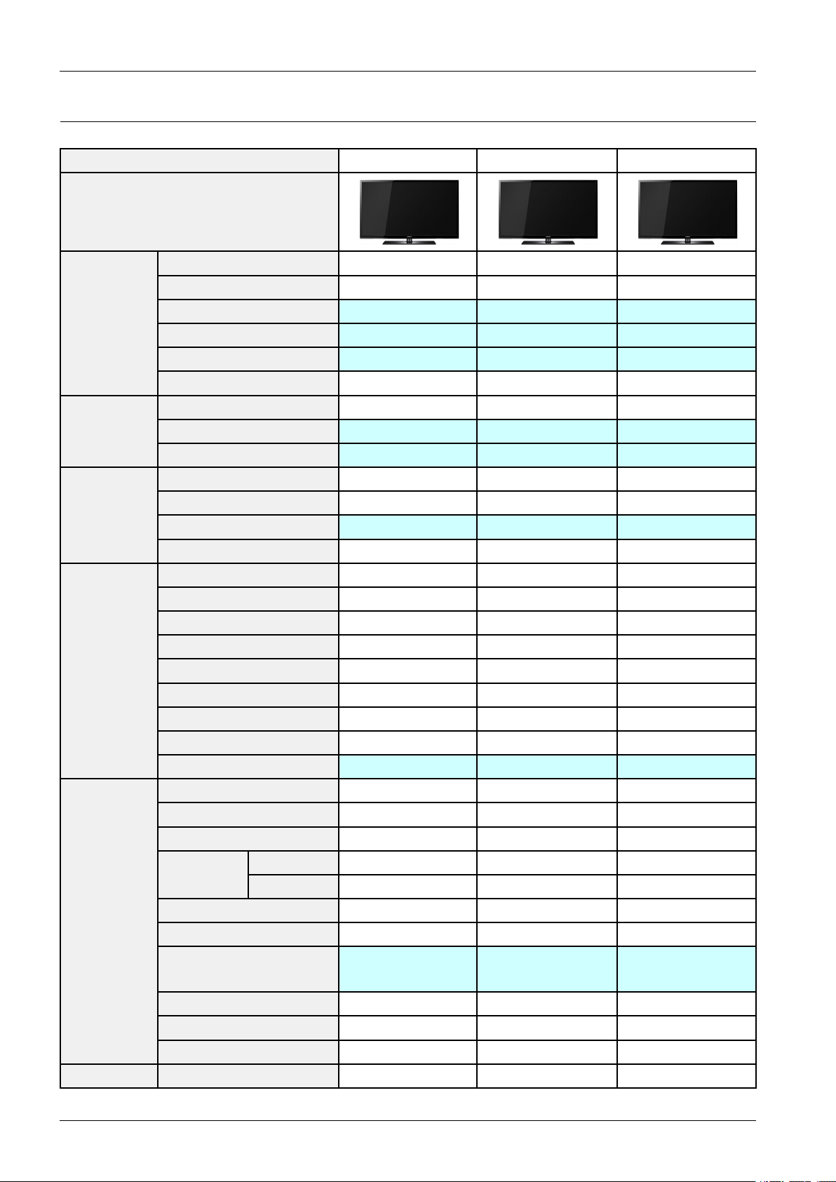
2.ProductSpecication
2.2.SpecicationsAnalysis
ModelP*43D4*0P*51D4*0P*42C450*
Design
DisplayTypePDPTVPDPTVPDPTV
Built-InT unerOOO
Basic
Audio
Features
Resolution1024x7681365x7681024x768
PDPModuleDHDHU2P
ScreenSize43inches51inches42inches
Pictureratio16:916:916:9
Brightness1,500Cd/m21,500Cd/m21,500Cd/m2
ContrastRatio10,000:110,000:130,000:1 Picture
PictureEnhacerDNIe(SEMS20)DNIe(SEMS20)DNIe
Equalizer5Band5Band5Band
AutoV olumeControlOOO
SurroundSoundSRSTheaterSoundSRSTheaterSoundSRSTruSurroundHD
SpeakerOutput10W+10W10W+10W10W+10W
PIPOOO
DoubleScreenXXX
CaptionOOO
StillImageXXX
EPGOOO
MycolorControlXXX
EnergySavingOOO
ScreenBurnProtectionOOO
AnynetXXO
Antenna1(Cable/Air)1(Cable/Air)1(Cable/Air)
A VInput1Input1Input1Input
S-VideoXXX
Component
Connections
Etc.Speaker/StandBuilt-inSpeakerBuilt-inSpeakerBuilt-inSpeaker
PC(D-SUB)1Input1Input1Input
DVIXXX
HDMI
USB111
SubWooferXXX
Optical111
W/W2Input2Input2Input
EU1Input1Input1Input
D490–3Input
D450–2Input
D490–3Input
D450–2Input
4Input
2-3Copyright©1995-2011SAMSUNG.Allrightsreserved.
Page 11

TIP
O:Supported,X:NotSupported
NOTE
Forthepowersupplyandpowerconsumption,refertothelabelattachedtotheproduct.
2.ProductSpecication
Copyright©1995-2011SAMSUNG.Allrightsreserved.2-4
Page 12
2.ProductSpecication
A B C D
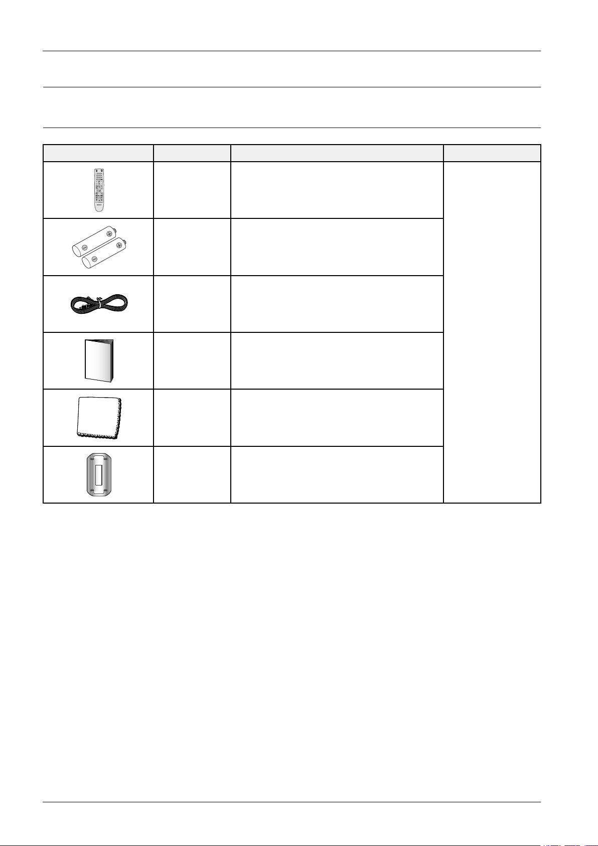
2.3.Accessories
2.3.1.SuppliedAccessories
AccessoriesItemItemcodeRemark
RemoteControlAA59-00487A
Batteries4301-000103
PowerCord3903-000461
Owner`s
Instructions
BN68-03498A
SamsungService
Center
Cloth-CleanBN63-01798B
FerriteCorefor
PowerCord
3301-002049
2-5Copyright©1995-2011SAMSUNG.Allrightsreserved.
Page 13
2.ProductSpecication
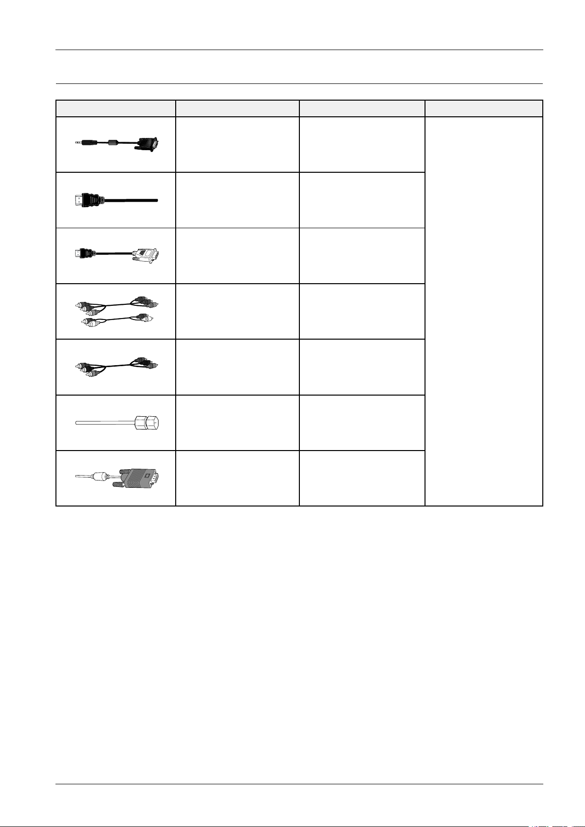
2.3.2.SoldSeparately
AccessoriesItemItemcodeRemark
RS232Cable-
HDMI-
HDMI-DVI-
Component-
Composite(A V)-
Coaxial(RF)-
VGA-
SamsungServiceCenter
Copyright©1995-2011SAMSUNG.Allrightsreserved.2-6
Page 14
3.Disassembly&Reassembly
3.Disassembly&Reassembly
3.1.OverallDisassembly&Reassembly
CAUTION
•Besuretoseparatethepowercordbefore
disassemblingtheunit.
•DischargethecapacitorsrstwhenseparatingPCB’s
withhighcapacitycapacitorssuchasSMPS,X
MainBoard,YMainBoard,etc.(Asparkmaybe
generatedbytheelectriccharge,andthereisdanger
ofelectronicshock.)
•Checkthatthecablesareproperlyconnected
referringtothecircuitdiagramwhendisassembling
orassemblingtheunittakingcarenottodamagethe
cables
•TakecarenottoscratchtheGlassFilterinthefront.
•Assembletheboardsinthereverseorderofthe
disassembly.
•Theplasmamustbelayeddownonaatpadded
surfacefordisassemblyandreassembly.
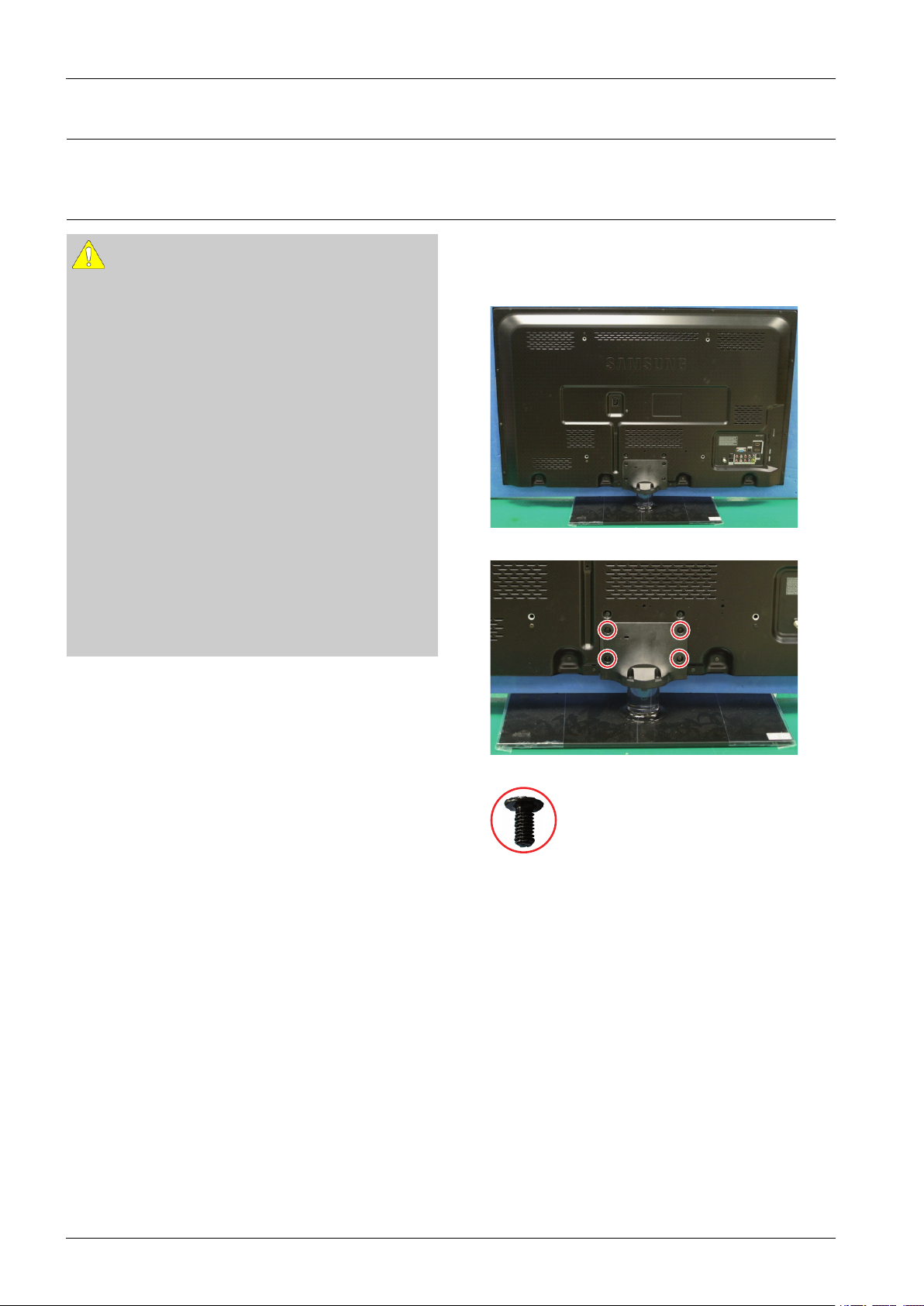
1.Placemonitorfacedownoncushionedtable.Remove
screwsfromtheStand.Removestand.
*Rearviewof43"
<43"PDP>
<43"PDP>
6001–002621:M4*L8
3-1Copyright©1995-2011SAMSUNG.Allrightsreserved.
Page 15
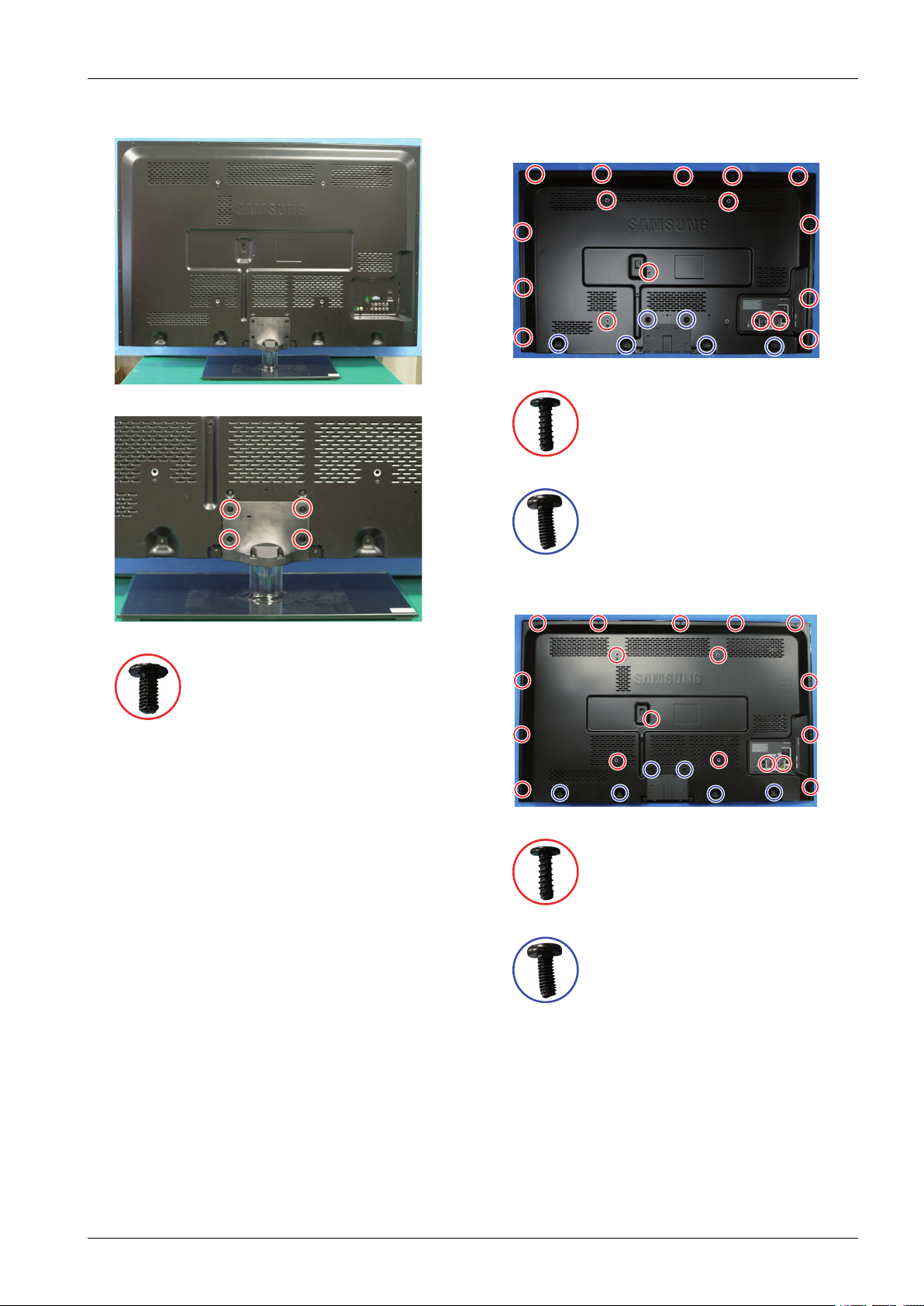
3.Disassembly&Reassembly
*Rearviewof51"
<51"PDP>
2.Removethescrewsofrear-cover.
*Rearviewof43"
<43"PDP>
6003–001782:M4*L12
6003–000337:M4*L10
<51"PDP>
6001–002621:M4*L8
*Rearviewof51"
<51"PDP>
6003–001782:M4*L12
6003–000337:M4*L10
Copyright©1995-2011SAMSUNG.Allrightsreserved.3-2
Page 16
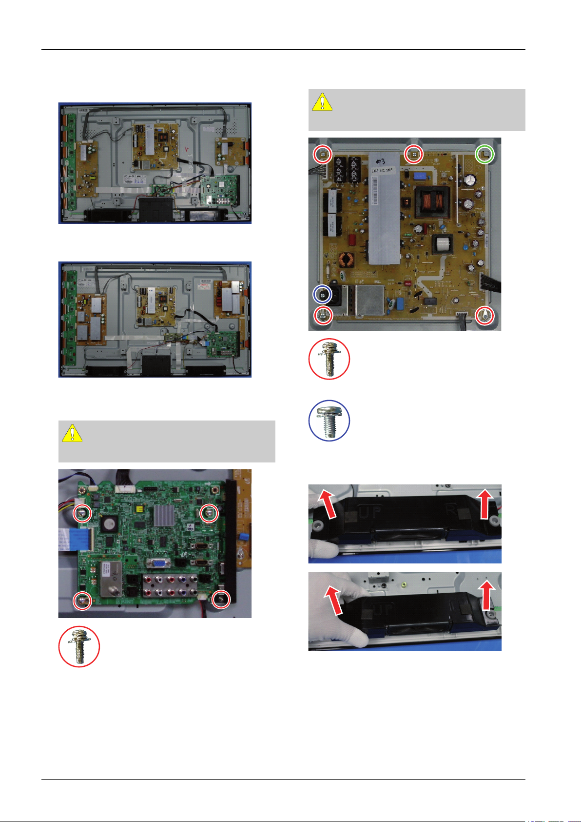
3.Disassembly&Reassembly
3.Liftupandremovetherear-cover.
*Rearviewof43"
<43"PDP>
*Rearviewof51"
5.RemovethescrewsofSMPS.RemovetheSMPS.
CAUTION
Alignboardundertabwhenre-installing.
<51"PDP>
4.Removethescrewsofmainboard.
CAUTION
Disconnectallconnectorspriortoremovingboards.
6001–002606:M3*L10
6003–001439:M4*L8
6.Removethespeakers.(R/L)
6001–002606:M3*L10
3-3Copyright©1995-2011SAMSUNG.Allrightsreserved.
Page 17
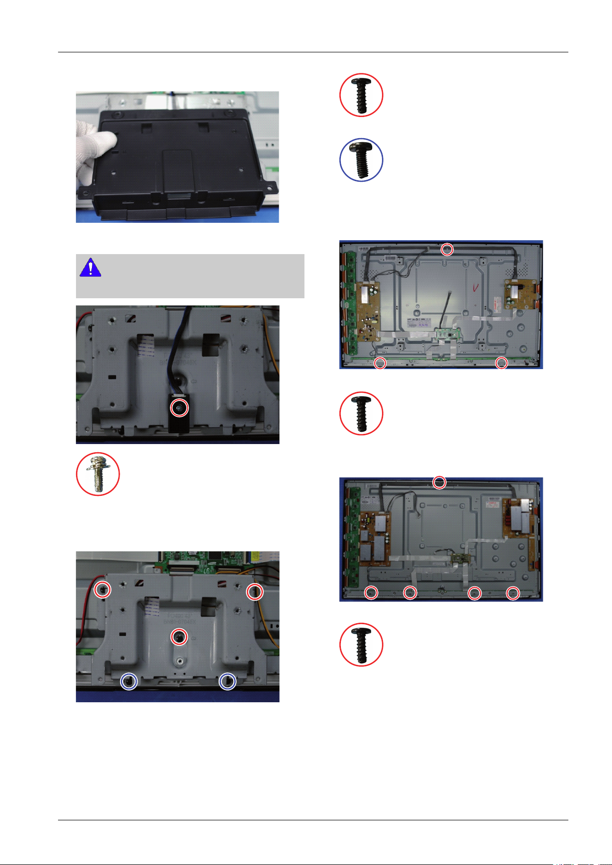
7.RemovetheCoverBottom.
8.RemovethescrewofBluetoothModule.
NOTE
PD49XSeriesOnly .
3.Disassembly&Reassembly
6003–001782:M4*L12
6003–000337:M4*L10
10.Removethescrewsofthefront-cover.
*Rearviewof43"
6001–002606:M3*L10
9.RemovethescrewsofBracketStandLink.Liftupthe
StandBracketStandLink.
<43"PDP>
6003–001782:M4*L12
*Rearviewof51"
<51"PDP>
6003–001782:M4*L12
Copyright©1995-2011SAMSUNG.Allrightsreserved.3-4
Page 18
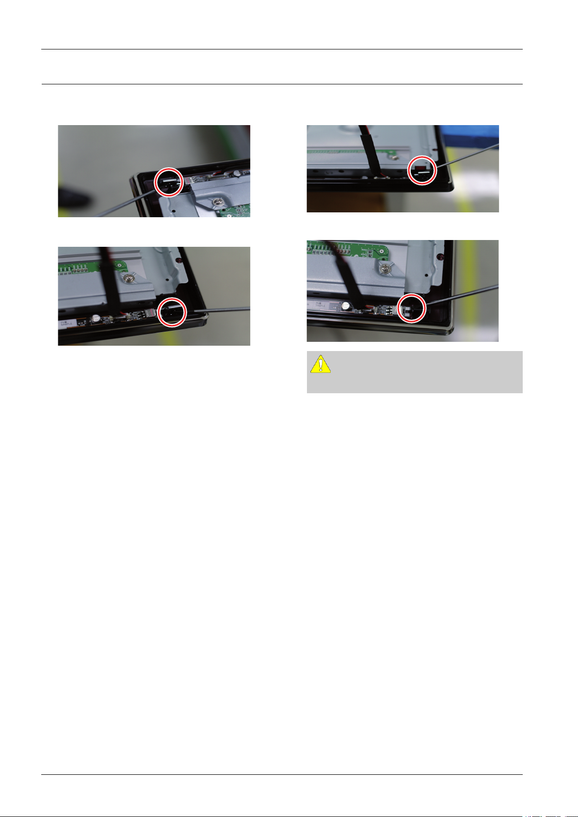
3.Disassembly&Reassembly
3.2.MethodforDisassemblyofFunctionAssy
1.PutuptheupperLocking,Usescrewdriver.
2.PutupthelowerLocking,Usescrewdriver.
3.RemoveLocking.
4.DetachtheFunctionPBA.
CAUTION
Disconnectallconnectorspriortoremovingboards.
3-5Copyright©1995-2011SAMSUNG.Allrightsreserved.
Page 19
4.Troubleshooting
4.1.CheckpointsbyErrorMode
4.1.1.FirstChecklistforTroubleshooting
1)Checkthevariouscableconnectionsrst.
•Checktoseeifthereisaburntordamagedcable.
•Checktoseeifthereisadisconnectedorloosecableconnection.
•Checktoseeifthecablesareconnectedaccordingtotheconnectiondiagram.
2)CheckthepowerinputtotheMainBoard.
3)HowtodistinguishiftheproblemiscausedbyMainboardorLogicBoard.
4.Troubleshooting
•NoVideo:IftheproblemisNoVideobutLogicBoardisonandIndicationLEDisblinkingrepeatedlyand
fasterthannormalbooting,replacetheT-Conboard.
•DistortedPicture:Checktheinnerpatterns.
InnerpatternPictureProblem
OKNGMainboard
NGNGMainorL VDScableorLogicBoardorPanel.
•Howtocheckinnerpattern?
a.Factorymode(mute→1→8→2→PoweronwhenTVisin‘stand-bymode’)
b.MovetoSVCmenu.
c.MovetoT estPattern.
d.Checkinnerpatterns.
Copyright©1995-2011SAMSUNG.Allrightsreserved.4-1
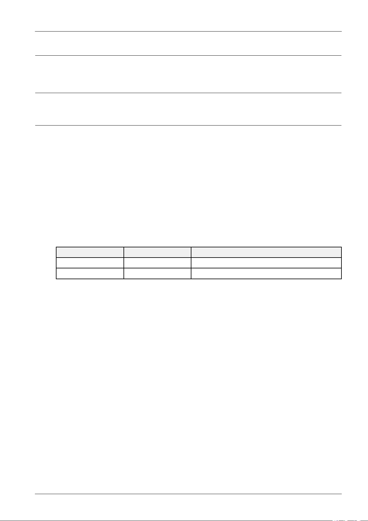
Page 20
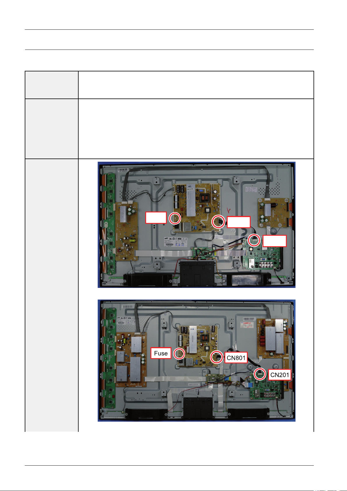
4.Troubleshooting
Fuse
CN801
CN201
Fuse
CN801
CN201
4.1.2.CheckpointsbyErrorMode
■NoPower
•TheLEDsonthefrontpaneldonotworkwhenconnectingthepowercord.
Symptom
MajorChecklist
•TheSMPSrelaydoesnotworkwhenconnectingthepowercord.
•Theunitappearstobedead.
TheSMPSrelayortheLEDsonthefrontpaneldoesnotworkwhenconnectingthepowercordif
thecablesareimproperlyconnectedortheMainBoardorSMPSisnotfunctioning.Inthiscase,
checkthefollowing:
•Checktheinternalcableconnectionstatusinsidetheunit.
•Checkthefusesofeachpart.
•ChecktheoutputvoltagesoftheSMPS.
•ReplacetheMainBoard.
<43"PDP>
<51"PDP>
Diagnostics
4-2Copyright©1995-2011SAMSUNG.Allrightsreserved.
Page 21
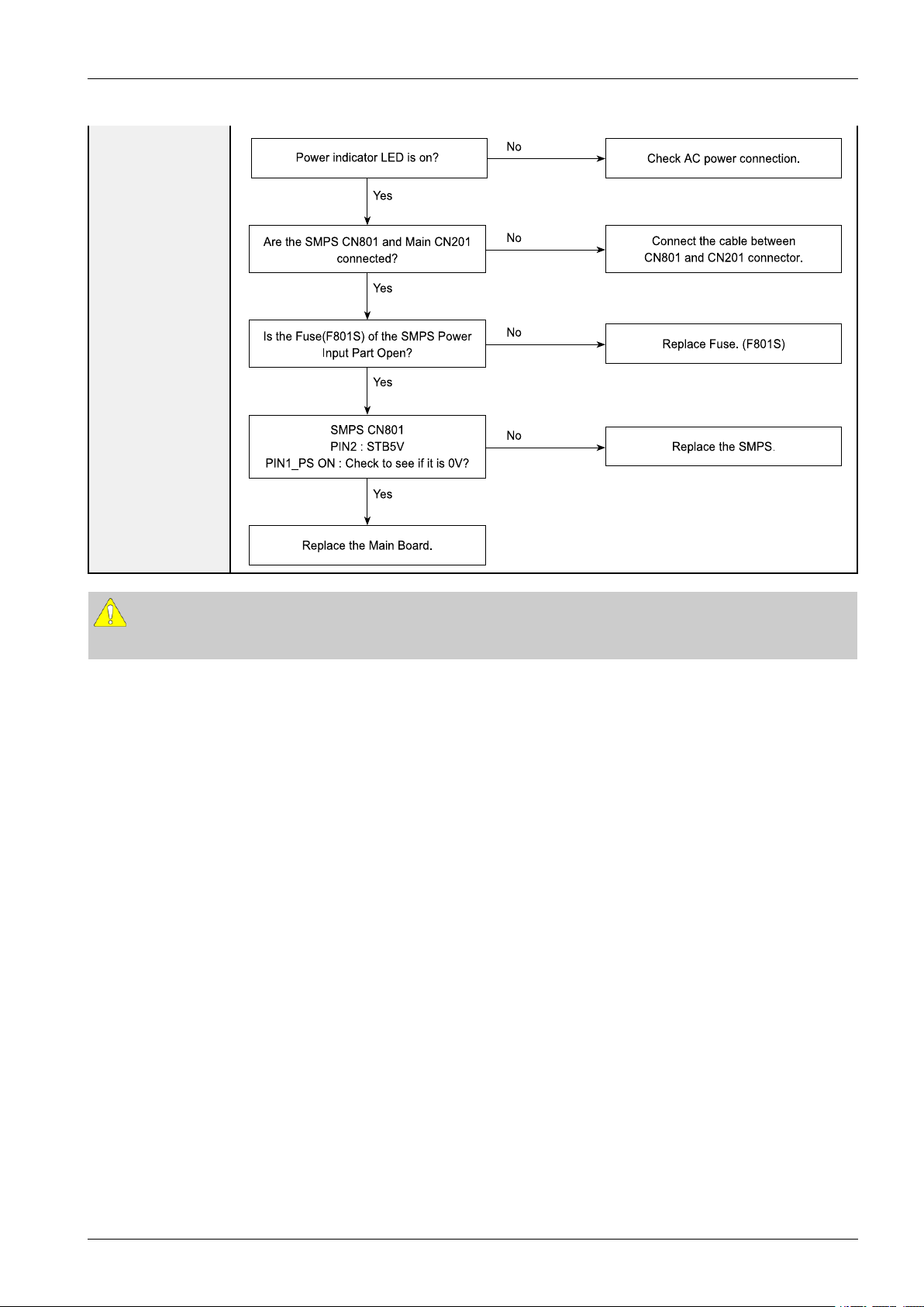
4.Troubleshooting
Yes
Yes
Yes
Yes
P owe r ind ica to r LED is o n?
Che ck AC powe r conn e ction.
Re p lace the Main Bo a rd.
Conn e ct the ca ble be twe en
CN801 a nd CN20 1 co nne c tor.
Are the SMPS CN801 a n d Main CN201
conn e cted?
Re p lace F use . (F 801S )
Is th e Fuse (F8 01S ) of the SMP S P ower
Input P a rt Ope n?
Re p lace the SMPS .
SMPS CN80 1
PIN2 : S TB5V
PIN1_ PS O N : Check to s ee if it is 0V?
No
No
No
No
CAUTION
MakesuretodisconnectthepowerbeforeworkingontheSMPSboard.
Copyright©1995-2011SAMSUNG.Allrightsreserved.4-3
Page 22

4.Troubleshooting
LVDS cable
LVDS cable
■NoVideo
Symptom•Audioisnormalbutnopictureisdisplayedonthescreen.
•TheoutputvoltageoftheMainSMPS.
MajorChecklist
•ThismayhappenwhentheLVDScableconnectingtheMainBoardandthePanelis
disconnected.
Diagnostics
<43"PDP>
<51"PDP>
4-4Copyright©1995-2011SAMSUNG.Allrightsreserved.
Page 23

4.Troubleshooting
Check the LED
Operation.
Yes
Yes
Yes
Re p lace th e Ma in Bo a rd.
Che ck / Repla ce the LVDS Ca b le.
Che ck the LVDS conn e ctor.
Is it con necte d corre ctly?
Re p lac e th e S MPS.
Che ck All output voltage s on SMPS .
Are all volta ges norma l?
Re p lac e th e Log ic Bo a rd.
Che ck the LED ope ra tion of Logic Board
whitch is no rmally ope ra ting?
(Norma l : Blink on ce a s e cond)
No
No
No
CAUTION
MakesuretodisconnectthepowerbeforeworkingontheSMPSboard.
Copyright©1995-2011SAMSUNG.Allrightsreserved.4-5
Page 24

4.Troubleshooting
Speaker
Speaker cable
CN801
■NoSound
Symptom•Videoisnormalbutthereisnosound.
•Whenthespeakerconnectorsaredisconnectedordamaged.
MajorChecklist
•WhenthesoundprocessingpartoftheMainBoardisnotfunctioning.
•Speakerdefect.
•SMPSnotsupplyingvoltagetothemainboard.
Diagnostics
<43"PDP>
<51"PDP>
4-6Copyright©1995-2011SAMSUNG.Allrightsreserved.
Page 25

4.Troubleshooting
Yes
Yes
Yes
Re place the S peake r.
Re place the S MPS.
Is th e o utp ut volta ge of SMPS norm a l?
(CN801 7pin : 15 V)
Re place the Ma in boa rd.
(1)
Is th e s peake r output termina l of
the Main boa rd normal?
Conn e ct the ca ble prop e rly or
repla ce the ca ble , if ne cessary.
Is th e c a ble c on nection betwee n
Main b oard a nd th e s peake r
prope rly co nn e cted?
No
No
No
Sound Output Shape
(1)
CAUTION
MakesuretodisconnectthepowerbeforeworkingontheIPboard.
Copyright©1995-2011SAMSUNG.Allrightsreserved.4-7
Page 26

4.Troubleshooting
4.1.3.FaultsandCorrectiveActions
SymptomRelatedImageCausesandCountermeasures
Ablankverticalcell(block)
appearsonthescreen.
•Addressbufferdefect
•Replacethecorrespondingupper/lowerbuffers.
(E,ForG)
•COFdefect(burnt)
•Replacethemodule.
Agreenscreenappearswhen
theTVisturnedon.
TheOSDboxappearsbut
thereisnotext.
Ablankupper(orlower)
blockappearsonthescreen.
•TheScaleisnotreseting.
•ReplacetheMainboard.
•Incorrectprogramversion.
•Checktheversionofeachprogram.
•ReplacetheMainboard.
•Upper/LowerYBufferdefect
•Replacethecorrespondingupper/lowerbuffers.
Eitherthemainorsubpicture
doesnotappear.
Averticalgreenlineappears
onthescreen.
4-8Copyright©1995-2011SAMSUNG.Allrightsreserved.
•ReplacetheMainboard.
•TheSMPSvoltageisincorrect.
•AdjusttheSMPSvoltageaccordingtothevoltage
printedonthemodulelabel.
Page 27

SymptomRelatedImageCausesandCountermeasures
4.Troubleshooting
Dimscreen(blurredinred)
•X-Mainboarddefect
•ReplacetheX-Mainboard.
Ablankscreenappears.•ReplacetheY -Mainboard.
Copyright©1995-2011SAMSUNG.Allrightsreserved.4-9
Page 28

4.Troubleshooting
OF F
ON
P owe r ON Logic ON S eq ue nce (P OS ) Norma l Togg ling
(e very 32 Vsync)
-. NT : 534 ms
-. P AL : 6 40 ms
540
ms
8 .06
s e c
Exce ption
540ms540ms540ms540
ms
27 Mhz
2 .44
s e c
163
ms
P LL ON
163ms163ms163ms163
ms
·
· ªª µµªª ¦¦ ¹¹ee
...
·
· ªª µµªª ¦¦ ¹¹ee
...
5
s e c
·
· ªª µµªª ¦¦ ¹¹ee
...
DR V_RES ET
2
s e c
4.1.4.OperatingLogicLED
■Normal
•LEDON/OFFfor0.5s
■Abnormal
•LEDON/OFFthreetimesfor8.1s
■DRV_RESET
•LEDONfor5sandLEDOFFfor2s
4-10Copyright©1995-2011SAMSUNG.Allrightsreserved.
Page 29

4.1.5.AdjustFunctionKeySensitivity
1)Select'Factory'
4.Troubleshooting
2)Select'Control'
Copyright©1995-2011SAMSUNG.Allrightsreserved.4-11
Page 30

4.Troubleshooting
3)Select'SubOption'
4)Select'KeySensitivity'
4-12Copyright©1995-2011SAMSUNG.Allrightsreserved.
Page 31

5)Defaultvalue(PD490=56,PD550=32)
No use 'Key Sens itivity' Very Sensitive Insensitive
4.Troubleshooting
6)AdjustTheValueofKeySensitivity
Copyright©1995-2011SAMSUNG.Allrightsreserved.4-13
Page 32

4.Troubleshooting
CN120 1
Pinmap
1. IR
2. GND
3. A3.3V
4. SCL
5. SDA
6. FUNC_INTR
7. LED_S TB
CN120 1
Pinmap
1. IR
2. GND
3. A3.3V
4. SCL
5. SDA
6. FUNC_INTR
7. LED_S TB
4.1.6.FunctionAssyPinMap
■USMainBoard
■EUMainBoard
4-14Copyright©1995-2011SAMSUNG.Allrightsreserved.
Page 33

4.1.7.AdjustSMPSVoltagewhenchangeSMPS
V
S _ TP
VS_VR
VA_TP
VA_VR
VS_TP
VS_VR
VA_TP
VA_VR
4.Troubleshooting
TIP
•T.P:TestPoint
•V .R:VariableResistor
Copyright©1995-2011SAMSUNG.Allrightsreserved.4-15
Page 34

4.Troubleshooting
¾¾ ÆÆ ´´ ÁÁoo oo
¾¾ ÆÆ ´´ ÁÁoo
¤¤oo
¤¤
¤¤ ££ oo
¾¾ ÆÆ ´´ ÁÁoo oo
¾¾ ÆÆ ´´ ÁÁoo ¤¤ ££ oo¦¦ ~~ ¦¦
INFO
Factory
4.2.FactoryModeAdjustments
4.2.1.EnteringFactoryMode
Toenter‘ServiceMode’Presstheremote-controlkeysinthissequence.
•IfyoudonothaveFactoryremote-control.
•IfyouhaveFactoryremote-control.
•Ifyoudon’thaveFactoryremotecontrol,can’tcontrolsomemenu.
Option
Control
SVC
Expert
ADC/WB
Advanced
T-MST4AUSC-0408.0
T-MST4AUSS-0019
E-Manual:X6A TSCA-0003
EDIDSUCCESS
HDCPSUCCESS
CALIB:AVOCOMPOPCOHMDIO
Option:2701,1374
SDAL-0.58.1.0
RFS:"Mstar-X50039"
KERNELMODULEVERSION:"00035_90"
2010-12-08
Type:51DFHcD
Model:PN51D550
MACSUCCESS
LOCDX
FactoryDataV er:68
EERCV ersion:501
DTP-AP-COMP-582
DTP-BP-HAL-0083
DTP-BP-0582
Dateofpurchase:mm/dd/yyyy
4-16Copyright©1995-2011SAMSUNG.Allrightsreserved.
Page 35

4.2.2.FactoryData
■Option
ItemDataRemark
FactoryReset-
Type43DHHcD
LocalSetxx
ModelPD490
Tunerxx
ChtableNONE
FrontColorT -R-BLK
■Control
MenuItemDataRemark
EDIDEDIDON/OFFON
4.Troubleshooting
EDIDWRITEALLSuccess
EDIDWRITEPCSuccess
EDIDWRITEHDMI...
EDIDWRITEHDMI1Success
EDIDWRITEHDMI2Success
EDIDWRITEHDMI3Success
EDIDWRITEHDMI4Success
HDMIEDIDVerHDMI1.2
HDMIEDIDPortNONE
EDIDWRITEDVI...
SubOptionRFMuteTime600ms
RS-232JackDebug
WatchdogOFF
WDCOUNT255
DimmType
LVDSFORMA TPDP
Language_Arabicxx
TOOLSSupport32
LNASupport0
MediaPlay
NETWORKSupportExt-Wi
InfoLinkServerT ypedevelopment
Copyright©1995-2011SAMSUNG.Allrightsreserved.4-17
DBOnwith
5MB
MOVIEchapterinmed
DLNAON
PlayListOFF
Page 36

4.Troubleshooting
MenuItemDataRemark
InfoLinkCountryNone
TTXList
TTXGroup
24Px4SupportOFF
PowerIndicatorSupportOFF
BDWiseSupportOFF
DataServiceSupportOFF
OTADurationTestOFF
AlternateDelOFF
OTNServerTypeoperating
OTNTestServerOFF
OTNSupportON
OTNReset
OTNDurationOFF
OTNFailTestOFF
IICBUSSTOPOFF
VisualTestDisable
EmergencyLogCopy
Checksum0x0000
ViewLog
SelectLogTypeIRKEY
LogView
DeleteLog
ColorSpaceSupportRGBT ype
GemstarOn/OffOFF
WSSSupportOFF
PVRSupportOFF
CISupportOFF
EepronReset
SpreadSpectrum
LVDSSpreadON
Period40K
Amplitude1.5
DDRSpread1.0%Spread
DDRMargin
ACTRL_OFFSET_0_30x0
ACTRL_OFFSET_D0x0
BCTRL_OFFSET_0_30x0
BCTRL_OFFSET_D0x0
H.264Margin8
MPEGMargin1000
TunerMargin10
4-18Copyright©1995-2011SAMSUNG.Allrightsreserved.
Page 37

MenuItemDataRemark
4.Troubleshooting
SST
Y0Ref165
Y1Ref148
Y2Ref119
Y3Ref101
Y4Ref76
Y5Ref60
Y6Ref31
Y7Ref0
Cb0Ref128
Cb1Ref64
Cb2Ref148
Cb3Ref85
Cb4Ref171
Cb5Ref108
Cb6Ref194
Cb7Ref0
Cr0Ref128
Cr1Ref137
Cr2Ref64
Cr3Ref74
Cr4Ref181
Cr5Ref192
Cr6Ref118
Cr7Ref0
SST_TH
Y0TH20
Y1TH20
Y2TH20
Y3TH20
Y4TH20
Y5TH20
Y6TH20
Y7TH20
Cb0TH20
Cb1TH20
Cb2TH20
Cb3TH20
Cb4TH20
Cb5TH20
Cb6TH20
Cb7TH20
Copyright©1995-2011SAMSUNG.Allrightsreserved.4-19
Page 38

4.Troubleshooting
MenuItemDataRemark
Cr0TH20
Cr1TH20
Cr2TH20
Cr3TH20
Cr4TH20
Cr5TH20
Cr6TH20
Cr7TH20
2ndmipsON
2ndmipscount0
Regionxxx
PnPLanguagexxx
PCAutoIdentEnable
OTPLock...
AutoPowerMEMORY
KEYSENSITIVITY561(VerySensitive)~255(Insensitive)
FANETOFF
OTASupportOFF
WIFIREGIONV
FKPDown
PDPOptionLOGICCONNECTOFF
PIXELSHIFTTESTOFF
PANELVERSIONDF
PANELINCH51FHD
PANELTYPE53
PANELTEMPERATURE40
LOGICIDA712
LOGICSWVERSION2010-11-20
LOGICSWCHECKSUM0xFC31
MRT44
SAPCTIMERON
APCSPEEDSLOW
Real100HzSupportOFF
XGAResolutionOFF
PLG_SHOP128
HotelOptionHOTELMODEON
POWERONCHANNEL
EN
User
Dened
POWERONCHANNEL3
CHANNELTYPECATV
4-20Copyright©1995-2011SAMSUNG.Allrightsreserved.
Page 39

MenuItemDataRemark
4.Troubleshooting
POWERONVOLUME
EN
POWERONVOLUME10
MINVOLUME0
MAXVOLUME100
PANELBUTTONLOCKUnlock
POWERONSOURCETV
PictureMenuLockOFF
MusicModeAVOFF
MusicModePCOFF
MusicModeCompOFF
MusicModeBacklightOFF
MenuDisplayON
PowerOnOptionLastOption
AutoSourceOFF
EnergySavingOFF
CloneTVtoUSB
CloneUSBtoTV
User
Dened
SettingAutoinitializeOFF
SIRCHUpdateTime2:00AM
MONITOROUTCVBSON
ShopOptionShopModeOFF
ExhibitionModeOFF
AsiaOptionTTXOFF
ChinaHDOFF
NTConversionOFF
Sepco120HzOFF
UnbalanceOFF
FMTransmitterSupportOFF
FMTransmitterCarrierOFF
AFLeveladjust3
TXpowerLevel0
MonoLastMemoryOFF
HShakingOFF
SOUNDHighDeviOFF
CarrierMuteON
V olumeCurveT ype1
SpeakerDelayNormal50
PilotLevelHighThld0x28h
PilotLevelLowThld0x10h
FMPrescale0
Copyright©1995-2011SAMSUNG.Allrightsreserved.4-21
Page 40

4.Troubleshooting
MenuItemDataRemark
AMPrescale0
NICAMPrescale0
AmpV olume0xc7h
AmpScale0x82h
WooferType1
WooferScale0x7fh
WooferCheckSum
SpeakerEQON
AmpModel0
Speakercut-offFreqNTP7411
SPDIFPCMGain-9dB
FMMPrescale48
BTSCMonoPrescale25
BTSCstereoPrescale47
SAPPrescale43
A2IdentHighThld31
A2IdentLowThld2
Carrier2AmpHighThld4
Carrier2AmpLowThld3
Carrier2SNRHighTHR16
Carrier2SNRLowTHR80
Audio-IPTestReady
TruBass-Checksum0x200190E2
PWMModeBD
CongOptionNumofATV1
NumofDTV1
NumofA V1
NumofSVIDEO0
NumofCOMP2
NumofHDMI4
NumofPC1
NumofSCART0
NumofDVI0
NumofOPTICALLink0
NumofMEDIA1
NumofPANELKEY6
NumofUSBPort2
NumofHeadPhone0
4-22Copyright©1995-2011SAMSUNG.Allrightsreserved.
Page 41

MenuItemDataRemark
NumofRVU0
MFTOffset62.5
SelectLCD/PDPPDP
HDMI/DVISEL1
IndicatorLedOFF
WallMountOFF
HVFlipOFF
NumOfDisplay2
DVI/HDMISOUNDAuto
HDMIHOTPLUGDisable
HOTPLUGSWITCHINGBoot
HOTPLUGDURA TION1200ms
4.Troubleshooting
CLKTERMDURA TION1200ms
HDMIFL TCNTSIG100ms
HDMIFL TCNTLOS100ms
UNSTABLEBANCNT3500ms
HDMIErrCnt1
HDMIROBINON
HDMICallbackOFF
HDMICTSThld8
HDMICTSCnt11
TMDS_EQ2_Boost1
TMDS_EQ2_Gain0
TMDS_PLL_Loop3
TMDS_CPREG_BLEED1
HDMIEQAuto
HDMIEDIDwRITETypeSeparate
HDMISwitchNONE
DVISETTIME300ms
TypeOfP ANELKEYPDPV ertical
EcoSensorSupportON
LEDMotionPlusSupportOFF
NaturalModeSupportOFF
AllShareSupportON
Copyright©1995-2011SAMSUNG.Allrightsreserved.4-23
Page 42

4.Troubleshooting
MenuItemDataRemark
RelaxModeSupportOFF
DVI-ISupport
MelfasFunctionSupport
LightLevelSupport
HWrite
HDMISyncDE
HeadPhonePortAOut2
SCCSCCModeDynamic
SCCON/OFFOFF
SCCInputData
Hx272
Hy278
Lx272
Ly278
sSCCConst
sSCCHx550
sSCCHy566
sSCCLx598
sSCCLy550
pSCCConst
pSCCHx550
pSCCHy566
pSCCLx598
pSCCLy550
SCCSourceDataPBA
SWAPPBA
4-24Copyright©1995-2011SAMSUNG.Allrightsreserved.
Page 43

■SVC
MenuItemDataRemark
TestPatternPatternSel...
LOGICPatternSel0
LOGICLevelSel255
PanelAutoSettingFailure
4.Troubleshooting
PANELDISPLA Y
TIME
LOGICUSBD/Loff
TunerStatus
T-CONUSB
Download
MICOM
UPGRADE
BTADDRESSe4e0c53197db
BTUPGRADE
SVCReset
2Hr
Failure
Off
■Expert
MenuItemDataRemark
N/DADJOFF
Source...
■ADC/WB
MenuItemDataRemark
ADCA VCalibration
CompCalibraion
PCCalibration
HDMICalibration
ADCT arget1st_A V_Low64
1st_A V_High880
1st_A V_Delta2
1st_COMP_Y_Low64
1st_COMP_Cb_Low512
1st_COMP_Cr_Low512
1st_COMP_Y_High940
1st_COMP_Cb_High512
1st_COMP_Cr_High512
1st_COMP_Delta2
1st_PC_Low4
1st_PC_High1004
Copyright©1995-2011SAMSUNG.Allrightsreserved.4-25
Page 44

4.Troubleshooting
MenuItemDataRemark
1st_PC_Delta2
2nd_ACH_Low4
2nd_ACH_High940
2nd_PC_Low4
2nd_PC_High940
2nd_Delta2
ADCResult1st_Y_GH258
1st_Y_GL128
1st_Cb_BH
1st_Cb_BL
1st_Cr_RH
1st_Cr_RL
2nd_R_L133
2nd_G_L133
2nd_B_L133
2nd_R_H70
2nd_G_H70
2nd_B_H70
WhiteBalanceSubBrightness128
R-Offset128
G-Offset128
B-Offset128
SubContrast128
R-Gain128
G-Gain128
B-Gain128
MovieR-Offset
MovieB-Offset
MovieR-Gain
MovieB-Gain
■Advanced
•Picture_2D
MenuItemDataRemark
SubSettingGamma0.95
NaturalGamma0
PwmMax100
PWMMin0
PwmMid0
ContrastDimmingOFF
4-26Copyright©1995-2011SAMSUNG.Allrightsreserved.
Page 45

MenuItemDataRemark
7.5IRENTSCOFF
7.5IREOffset
CompPhase110
LedPeakOnOffOFF
DitherBypassOFF
DMotionLightOn
DynamicContrastOn
EPAStandardStandardContrast100
StandardBrightness45
StandardSharpness50
StandardColor50
StandardTint0
StandardBacklight10
WBMovieW/BMovieOn/OffOFF
4.Troubleshooting
Model...
ColorTone...
MsubBrightness...
MsubContrast...
N_Rgain...
N_Bgain...
N_Roffset...
N_boffset...
W2_Rgain...
W2_Bgain...
W2_Roffset...
W2_Boffset...
MovieContrast...
MovieBright...
MovieColor...
MovieSharpness...
MovieTint...
MovieBacklight...
MovieGamma...
M_Sub_Gamma...
HDMIBlackLevel...
WCEWRHue64
WRSat16
WYHue64
WYSat16
WGHue64
Copyright©1995-2011SAMSUNG.Allrightsreserved.4-27
Page 46

4.Troubleshooting
MenuItemDataRemark
WGSat16
WCHue64
WCSat16
WBHue64
WBSat16
WMHue64
WMSat16
ARHue64
ARSat16
AYHue64
AYSat16
AGHue64
AGSat16
ACHUE64
ACSat16
ABHue64
ABSat16
AMHue64
AMSat16
VDECAGCmode3
AGCmanualgain72
Ifcomptype1
Ifcompsel15
SaturainCb/Cr145
SecamFilterSel0
RGBDelay150
PeakingGain0
CoringGain3
ChromaPeak10
2DVPeaking0
2DHPeaking0
2DPeakingGain0
SharpnessPost_H120
Post_H226
Post_H320
Post_H415
Post_v120
Post_v218
Post_H2Overshoot128
Post_H2Undershoot128
4-28Copyright©1995-2011SAMSUNG.Allrightsreserved.
Page 47

MenuItemDataRemark
Post_H3Overshoot128
Post_H3undershoot128
CoreGain12
CoreGain23
D_Tot_Gain24
S_Tot_Gain24
ColorMappingA_Red_R60
A_Red_G0
A_Red_B0
A_Green_R67
A_Green_G100
A_Green_B0
A_Blue_R0
A_Blue_G49
4.Troubleshooting
A_Blue_B100
A_Yellow_R100
A_Yellow_G100
A_Yellow_B0
A_Cyan_R0
A_Cyan_G46
A_Cyan_B100
A_Magenta_R27
A_Magenta_G0
A_Magenta_B67
N_Red_R50
N_Red_G0
N_Red_B0
N_Green_R0
N_Green_G50
N_Green_B0
N_Blue_R0
N_Blue_G0
N_Blue_B50
N_Yellow_R50
N_Yellow_G50
N_Yellow_B0
N_Cyan_R0
N_Cyan_G50
N_Cyan_B50
N_Magenta_R50
Copyright©1995-2011SAMSUNG.Allrightsreserved.4-29
Page 48

4.Troubleshooting
MenuItemDataRemark
N_Magenta_G0
N_Magenta_B50
EnhanceBLE_Gain22
DSubColor80
DSkinHue84
DSkinSat18
SSubColor80
SSkinHue72
SSkinSat16
MSubColor55
MSkinHue64
MSkinSat16
SubTint45
CE_Normal_Left_Gain35
CE_Normal_Right_Gain20
CE_Normal_Offset-10
CE_Special_Left_Gain15
CE_Special_Right_Gain10
CE_Special_Offset-50
CE_S_Left_gain10
CE_S_Right_Gain40
CE_S_Normal_Offset-2
LNA_PlusSynctip_Noise102
dB01_th3
dB12_th4
dB23_th6
dB34_th8
dB45_th10
dB56_th12
dB67_th15
dB78_th28
LNA_Plus_Yller3
YC_DelayRFPALBG10
RFP ALDK11
RFP ALI13
RFP ALM6
RFP ALn11
RFSECAMBG5
RFSECAMDK8
RFSECAML8
4-30Copyright©1995-2011SAMSUNG.Allrightsreserved.
Page 49

MenuItemDataRemark
RFNT35814
RFNT4438
A VPAL9
A VPALM7
A VPALN9
A VSECAM9
A VNT35810
A VNT4434
A VPal606
SCARTPAL9
SCARTPALM9
SCARTPALN9
SCARTSECAM4
SCARTNT35810
4.Troubleshooting
SCARTNT4434
SCARTPAL606
SCARTRGBP AL8
SCARTRGBP ALM8
SCARTRGBP ALN8
SCARTRGBSECAM8
SCARTRGBNT3588
SCARTRGBNT4438
SCARTRGBPAL608
PictureUpdate
•Picture_3D
MenuItemDataRemark
SubSetting_3D3D_Gamma0.95
3D_NaturalGamma0
3D_PwmMax100
3D_PWMMin0
3D_PwmMid0
3D_Contrast
Dimming
3D_LedPeak
OnOff
3D_DitherBypassOFF
3D_DMotionLightOFF
3D_Dynamic
Contrast
EPA_3D3DContrast100
Copyright©1995-2011SAMSUNG.Allrightsreserved.4-31
OFF
OFF
OFF
Page 50

4.Troubleshooting
MenuItemDataRemark
3DBrightness45
3DStandard
Sharpness
3DStandardColor50
3DStandardTint0
3DStandard
Backlight
WBMovie_3D3D_W/BMovie
On/Off
3D_Model...
3D_ColorT one...
3D_Msub
Brightness
3D_MsubContrast...
3D_C_Rgain...
3D_C_Bgain...
3D_C_Roffset...
3D_C_boffset...
3D_N_Rgain...
3D_N_Bgain...
50
7
OFF
...
3D_N_Roffset...
3D_n_Boffset...
3D_W2_Rgain
3D_W2_Bgain
3D_W2_Roffset
3D_W2_Boffset
3D_MovieContrast...
3D_MovieBright...
3D_MovieColor...
3D_Movie
Sharpness
3D_MovieTint...
3D_Movie
Backlight
3D_MovieGamma...
3D_M_Sub_Gamma...
3D_HDMIBlack
Level
...
...
...
3D_SubContrast128
3D_Sub_Brightness128
WCE_3D3D_WRHue64
3D_WRSat17
4-32Copyright©1995-2011SAMSUNG.Allrightsreserved.
Page 51

MenuItemDataRemark
3D_WYHue72
3D_WYSat17
3D_WGHue47
3D_WGSat17
3D_WCHue58
3D_WCSat17
3D_WBHue54
3D_WBSat18
3D_WMHue64
3D_WMSat17
3D_ARHue64
3D_ARSat16
3D_AYHue64
3D_AYSat16
4.Troubleshooting
3D_AGHue64
3D_AGSat16
3D_ACHUE64
3D_ACSat16
3D_ABHue64
3D_ABSat16
3D_AMHue64
3D_AMSat16
ColorMapping_3D3D_A_Red_R50
3D_A_Red_G0
3D_A_Red_B0
3D_A_Green_R0
3D_A_Green_G50
3D_A_Green_B0
3D_A_Blue_R0
3D_A_Blue_G0
3D_A_Blue_B50
3D_A_Yellow_R50
3D_A_Yellow_G50
3D_A_Yellow_B0
3D_A_Cyan_R0
3D_A_Cyan_G50
3D_A_Cyan_B50
3D_A_Magenta_R50
3D_A_Magenta_G0
3D_A_Magenta_B50
Copyright©1995-2011SAMSUNG.Allrightsreserved.4-33
Page 52

4.Troubleshooting
MenuItemDataRemark
3D_N_Red_R50
3D_N_Red_G0
3D_N_Red_B0
3D_N_Green_R0
3D_N_Green_G50
3D_N_Green_B0
3D_N_Blue_R0
3D_N_Blue_G0
3D_N_Blue_B50
3D_N_Yellow_R50
3D_N_Yellow_G50
3D_N_Yellow_B0
3D_N_Cyan_R0
3D_N_Cyan_G50
3D_N_Cyan_B50
3D_N_Magenta_R50
3D_N_Magenta_G0
3D_N_Magenta_B50
Sharpness_3D3D_Post_H116
3D_Post_H210
3D_Post_H310
3D_Post_H410
3D_Post_v120
3D_Post_v214
3D_Post_H2
Overshoot
3D_Post_H2
Undershoot
3D_Post_H3
Overshoot
3D_Post_H3
undershoot
3D_CoreGain11
32
32
16
16
3D_CoreGain22
3D_D_Tot_Gain28
3D_S_Tot_Gain28
Enhance_3D3D_BLE_Gain22
3D_DSubColor65
3D_DSkinHue100
3D_DSkinSat18
3D_SSubColor65
4-34Copyright©1995-2011SAMSUNG.Allrightsreserved.
Page 53

MenuItemDataRemark
3D_SSkinHue72
3D_SSkinSat16
3D_MSubColor55
3D_MSkinHue64
3D_MSkinSat16
3D_SubTint50
3D_CE_Normal_Left_Gain20
3D_CE_Normal_Right_Gain30
3D_CE_Normal_Offset-10
3D_CE_Special_Left_Gain15
3D_CE_Special_Right_Gain10
3D_CE_Special_Offset-50
3D_CE_S_Left_gain10
3D_CE_S_Right_Gain40
4.Troubleshooting
3D_CE_S_Normal_Offset-2
3DSettingBTPairDis_Ho2
LED_BT_IR
BTPairDis_sh25
BTTransDis10
BTSlaveDelay480
BTSlaveDelay500
BTSlaveDelay600
BTEmiDel_480
BTEmiDel_500
BTEmiDel_600
BTGlsDUTY100
IREmiDel_480
IREmiDel_500
IREmiDel_600
IREmiMask1
IRMASKPRD1
IREmiNum1
SlavDelay480
SlavDelay500
SlavDelay600
Copyright©1995-2011SAMSUNG.Allrightsreserved.4-35
Page 54

4.Troubleshooting
MenuItemDataRemark
PDP_BT_IR
BTPairDis_Ho_PDP2
BTPairDis_sh_PDP25
BTTransDis_PDP10
BTSlaveDelay48_D0
BTSlaveDelay50_D0
BTSlaveDelay60_D0
BTGlsDUTY_D100
BTEmiDel_48_S0
BTEmiDel_50_S0
BTEmiDel_60_S0
BTGlsDUTY_S100
IREmiDel_48_R0
IREmiDel_50_R0
IREmiDel_60_R0
BTGlsDUTY_R100
BTEmiDel_48_M0
BTEmiDel_50_M0
BTEmiDel_60_M0
BTGlsDUTY_M100
IREmiMask_PDP1
IRMASKPRD_PDP1
IREmiNum_PDP1
SlavDelay48_PDP0
SlavDelay50_PDP0
SlavDelay60_PDP0
Duty
PDuty19225
PDuty20025
PDuty240_Dyn25
PDuty210_Mov25
Dcc
Glmit_LBT088
Glmit_LBT189
Glmit_LBT290
Glmit_LBT391
Glmit_LLT095
Glmit_LLT196
Glmit_LLT297
Glmit_LLT398
DCCX10
DCCX20
DCCX30
4-36Copyright©1995-2011SAMSUNG.Allrightsreserved.
Page 55

MenuItemDataRemark
DCCY10
DCCY20
DCCH10
DCCH20
DCCH30
DCCV10
DCCV20
TempRead0
Time_HOT120
Time_Cold120
Temp_ST16
Temp_TH40
delta5
4.Troubleshooting
Effect
Depth_Min10
Depth_Max100
Viewp_Min_2D3D64
Viewp_Max_2D3D192
Viewpoint_Min64
viewpoint_Max192
Debug
DebugOFF
DccMode0
DccSele0_00
DccSele0_10
DccSele0_20
DccSele0_30
DccSele0_40
DccSele0_50
DccSele0_60
DccSele0_70
PosiSel_0_00
PosiSel_0_10
PosiSel_0_20
PosiSel_0_30
PosiSel_0_40
PosiSel_0_50
PosiSel_0_60
PosiSel_0_70
PosiSel_0_80
PosiSel_0_90
PosiSel_0_100
Copyright©1995-2011SAMSUNG.Allrightsreserved.4-37
Page 56

4.Troubleshooting
MenuItemDataRemark
PosiSel_0_110
BypassOFF
4-38Copyright©1995-2011SAMSUNG.Allrightsreserved.
Page 57

4.3.ServiceAdjustment
ADC / WB
AV Calibration
Comp Calibration
PC Calibration
HDMI Calibration
-Y oumustperformCalibrationintheLatticePatternbeforeadjustingtheWhiteBalance.
■WhiteBalance-Calibration
•Factory
■ColorCalibration
•Adjustspec.
1)Source:HDMI
4.Troubleshooting
2)SettingMode:1280*720@60Hz
3)Pattern:Pattern#24(ChessPattern)
4)UseEquipment:CA210&MasterMSPG925Generator
UseotherequipmentonlyaftercomparingTheresultwiththatofTheMasterequipment.
InputmodeCalibrationPattern
CVBSIN(Model_#1)PerforminNTSC/P ALB&WPattern#24Lattice
ComponentIN(Model_#6)Performin720pB&WPattern#24Lattice
PCAnalogIN(Model_#21)PerforminVESAXGA(1024x768)B&WPattern#24Lattice
HDMIINPerformin720pB&WPattern#24Lattice
Copyright©1995-2011SAMSUNG.Allrightsreserved.4-39
Page 58

4.Troubleshooting
•MethodofColorCalibration(A V)
1)ApplytheNTSC/PALLattice(N0.3)patternsignaltotheA VIN1port.
2)PresstheSourcekeytoswitchto“A V1”mode.
3)EnterServicemode.
4)Selectthe“ADC”menu.
5)Selectthe“AVCalibration”menu.
6)In“AVCalibrationOff”status,pressthe“
7)WhenCalibrationiscomplete,itreturnstothehigh-levelmenu.
8)Y oucanseethechangeofthe“A VCalibration”statusfromFailuretoSuccess.
”keytoperformCalibration.
•MethodofColorCalibration(Component)
1)Applythe720pLattice(N0.6)patternsignaltotheComponentIN1port.
2)PresstheSourcekeytoswitchto“Component1”mode.
3)EnterServicemode.
4)Selectthe“ADC”menu.
5)Selectthe“CompCalibration”menu.
6)In“CompCalibrationOff”status,pressthe“
7)WhenCalibrationiscomplete,itreturnstothehigh-levelmenu.
8)Y oucanseethechangeofthe“CompCalibration”statusfromFailuretoSuccess.
”keytoperformCalibration.
•MethodofColorCalibration(PC)
1)ApplytheVESAXGALattice(N0.21)patternsignaltothePCINport.
2)PresstheSourcekeytoswitchto“PC”mode.
3)EnterServicemode.
4)Selectthe“ADC”menu.
5)Selectthe“PCCalibration”menu.
6)In“PCCalibrationOff”status,pressthe“
7)WhenCalibrationiscomplete,itreturnstothehigh-levelmenu.
8)Y oucanseethechangeofthe“PCCalibration”statusfromFailuretoSuccess.
”keytoperformCalibration.
4-40Copyright©1995-2011SAMSUNG.Allrightsreserved.
Page 59

•MethodofColorCalibration(HDMI)
ADC / WB - White Balance
Factory (Low light) (High light)
Sub Bright
R offset
G offset
B offset
Sub Contrast
R gain
G gain
B gain
1)Applythe720pLattice(N0.6)patternsignaltotheHDMI1/DVIINport.
2)PresstheSourcekeytoswitchto“HDMI1”mode.
3)EnterServicemode.
4)Selectthe“ADC”menu.
5)Selectthe“HDMICalibration”menu.
4.Troubleshooting
6)In“HDMICalibrationOff”status,pressthe“
7)WhenCalibrationiscomplete,itreturnstothehigh-levelmenu.
8)Y oucanseethechangeofthe“HDMICalibration”statusfromFailuretoSuccess.
”keytoperformCalibration.
■WhiteBalance-Adjustment
Copyright©1995-2011SAMSUNG.Allrightsreserved.4-41
Page 60

4.Troubleshooting
4.4.SoftwareUpgrade
SamsungmayofferupgradesfortheTV’srmwareinthefuture.
TheseupgradescanbeperformedviatheTVwhenitisconnectedtotheInternet,orbydownloadingthenewrmware
fromsamsung.comtoaUSBmemorydevice.
•AlternativeSoftware(Backup)showsThepreviousversionthatwillbereplaced.
•Softwareisrepresentedas‘Y ear/Month/Day_Version’.
Themorerecentthedate,thenewerthesoftwareversion.
Installingthelatestversionisrecommended.
■ByUSB
InsertaUSBdrivecontainingthermwareupgradedownloadedfromsamsung.comintotheTV .Pleasebecarefultonot
disconnectthepowerorremovetheUSBdrivewhileupgradesarebeingapplied.
TheTVwillturnoffandturnonautomaticallyaftercompletingthermwareupgrade.Pleasecheckthermwareversion
aftertheupgradesarecomplete(thenewversionwillhaveahighernumberthantheolderversion).haveahighernumber
thantheolderversion)madewillreturntotheirdefault(factory)settings.
Werecommendyouwritedownyoursettingssothatyoucaneasilyresetthemaftertheupgrade.
4-42Copyright©1995-2011SAMSUNG.Allrightsreserved.
Page 61

■ByOnline
UpgradesthesoftwareusingtheInternet.
•First,congureyournetwork.FordetailedproceduresonusingtheNetworkSetting.
Refertothe‘SettingtheNetwork’instructions.
•IfTheinternetconnectiondoesn’toperateproperly ,connectioncanbebroken,pleaseretrydownloading.
Iftheproblemstillhappens,downloadbyUSBandupgrade.
4.Troubleshooting
■AlternativeSoftware(Backup)
Ifthereisanissuewiththenewrmwareanditisaffectingoperation,youcanchangethesoftwaretotheprevious.
•IfSoftwarewaschanged,existingSoftwareisdisplayed.
•YoucanchangecurrentSoftwaretoAlternativeSoftwareby‘AlternativeSoftware’.
Copyright©1995-2011SAMSUNG.Allrightsreserved.4-43
Page 62

5.WiringDiagram
CN55 00
CN55 01
CN55 02
CN55 03
CN55 04
CN55 05
CN50 09
CN50 10
CN50 11
Y-DRIVE
SMP S
X-DR IVE
MAIN BOARD
LOGIC BOAR D
E-BUFF ER
CN40 00
CN40 02
FUNCTION
BLUETOO TH
SP EAKER
CN50 03
CN50 00
CN80 0S
CN50 02
CN50 01
CN80 4
CN80 1
CN80 2
CNXX
CN40 04
CN25 01
CN25 00
CN26 00
CN25 02
CN26 01
CN20 1
CN12 01
CN16 02_ HD
CN30 2
CN1
F-BUF FER
CN60 3_ 3D
CN20 21
CN20 01
CN20 10
CN20 09
CN20 23
CN20 22
1
2
3
4
5
6
7
..
¤¤ ££ ££ oo oo §§ oo ¢¢ ´´ ÁÁ ¸¸´´  oo ½½ »»ÈÈ }} oo
5.WiringDiagram
5.1.OverallWiring
■43"HDOverallWiring
5-1Copyright©1995-2011SAMSUNG.Allrightsreserved.
Page 63

■51"HDOverallWiring
CN55 05
CN55 04
CN55 03
CN55 00
CN55 01
CN55 02
CN50 02
CN50 04
CN50 03
CN50 05
Y-DRIVE
X-DRIVE
SMP S
MAIN BOARD
LOGIC BO ARD
E-BUFF ER
CN49 06
CN44 04
CN44 06
CN49 04
FUNC TION
BLUE TOOTH
SP EAKER
CN50 01
CN50 00
CN80 0S
CN50 06
CN50 07
CN80 4
CN80 1
CN80 2
CN47 01
CN40 01
CN25 01
CN25 00
CN26 00
CN25 02
CN26 01
CN20 1
CN12 01
CN16 02_ HD
CN30 2
CN1
F-BUF FE R
CN60 3_ 3D
CN20 21
CN20 02
CN20 10
CN20 11
CN20 23
CN20 22
1
2
3
4
5
6
7
..
¤¤ ££ ££ oo oo §§ oo¢¢ ´´ ÁÁ ¸¸´´  oo ½½ »»ÈÈ }} oo
5.WiringDiagram
Copyright©1995-2011SAMSUNG.Allrightsreserved.5-2
Page 64

5.WiringDiagram
NOTE
Thecodenumberofcable(Lead-connector)canbechanged,see“ExplodedViewsandPartsList”.
■43"Cable(Lead-connector)
Use
CodeBN39-01285KBN96-13325G
Photo
(1)
POWER12Pin
LVDSFFC51Pin
(7)
■51"Cable(Lead-connector)
Use
CodeBN39-01285LBN96-13325F
Photo
(1)
POWER12Pin
LVDSFFC51Pin
(7)
5-3Copyright©1995-2011SAMSUNG.Allrightsreserved.
Page 65

5.1.1.PinConnection
(1)
CN801(SMPS)↔CN201(MainBoard)
PinNo.(SMPS)Signal(SMPS)PinNo.(MainBoard)Signal(MainBoard)
1PS-ON1SW_POWER
2STBY2A5V_PW
3GND3DGND
4D15V4B15VS_PW
5GND5DGND
6GND6DGND
7D5.3V7B5V_PW
8D5.3V8B5V_PW
9GND9DGND
10D15V10B15V_PW
11D15V11B15V_PW
5.WiringDiagram
12D5.3V12B5V_PW
(2)
CN804(SMPS)↔CN5000(YBoard)
PinNo.(SMPS)Signal(SMPS)PinNo.(YBoard)Signal(YBoard)
1208V1Vs
2208V2Vs
3GND3GND
4D15V4Vg(15V)
5GND5GND
6V A6Va
(3)
43"only:CN802(SMPS)↔CN2001(LogicBoard)
51"only:CN802(SMPS)↔CN2002(LogicBoard)
PinNo.(SMPS)Signal(SMPS)PinNo.(LogicBoard)Signal(LogicBoard)
1D5.3V15.3V
2D5.3V25.3V
3GND3GND
4VS-SIGNAL4GND
5PS-ON5PS_ON
6VS-ON6VS_ON
Copyright©1995-2011SAMSUNG.Allrightsreserved.5-4
Page 66

5.WiringDiagram
(4)
CN603D_3D(MainBoard)↔BLUETOOTH
PinNo.(MainBoard)Signal(MainBoard)PinNo.(BLUETOOTH)Signal(BLUETOOTH)
1FRAME_SYNC_IN1Reset_Module
2FRAME_SYNC_OUT2VCC5V
3DGND3USBD-(BT)
4USB_BT_DP4USBD+(BT)
5USB_BT_DM5GND
6A5V_PM63DSyncOut
7FUNC_INTR73DSyncIn
8POWER_DET8
(5)
CN1201(MainBoard)↔CN1(FUNCTION)
PinNo.(MainBoard)Signal(MainBoard)PinNo.(FUNCTION)Signal(FUNCTION)
1IR1IR
2FUNC_GND2GND
3FUNC_A3.3V3A3.3V
4MSCT4SCL
5MSDA5SDA
6FUNC_INTR6INT
7LED_STR7LED
(6)
CN302(MainBoard)↔SPEAKER
PinNo.(MainBoard)Signal(MainBoard)
1R+_OUT
2R-_OUT
3L+_OUT
4L-_OUT
5-5Copyright©1995-2011SAMSUNG.Allrightsreserved.
Page 67

5.WiringDiagram
43”(7)
CN2023(LogicBoard)↔CN1602_HD(MainBoard)2DOnly
PinNo.SignalPinNo.SignalPinNo.SignalPinNo.Signal
1GND14RIGHT(4)+27RIGHT(0)-40GND
2UARTTx15RIGHT(4)-28GND41GND
3GND16RIGHT(3)+29GND42GND
4SDA17RIGHT(3)-30GND43GND
5GND18GND31GND44GND
6SCL19RightCLK+32GND45GND
7GND20RightCLK-33GND46GND
8UARTRx21GND34GND47GND
9GND22RIGHT(2)+35GND48GND
10GND23RIGHT(2)-36GND493D_SYNC
11GND24RIGHT(1)+37GND50GND
12N/C25RIGHT(1)-38GND51PDP_GO
13GND26RIGHT(0)+39GND
51”(7)
CN2023(LogicBoard)↔CN1602_HD(MainBoard)2DOnly
PinNo.SignalPinNo.SignalPinNo.SignalPinNo.Signal
1GND14RIGHT(4)+27RIGHT(0)-40LEFT(1)-
2UARTTx15RIGHT(4)-28GND41LEFT(0)+
3GND16RIGHT(3)+29LEFT(4)+42LEFT(0)-
4SDA17RIGHT(3)-30LEFT(4)-43GND
5GND18GND31LEFT(3)+44GND
6SCL19RightCLK+32LEFT(3)-45GND
7GND20RightCLK-33GND46GND
8UARTRx21GND34LEFTCLK+47GND
9GND22RIGHT(2)+35LEFTCLK-48GND
10GND23RIGHT(2)-36GND493D_SYNC
11GND24RIGHT(1)+37LEFT(2)+50GND
12N/C25RIGHT(1)-38LEFT(2)-51PDP_GO
13GND26RIGHT(0)+39LEFT(1)+
Copyright©1995-2011SAMSUNG.Allrightsreserved.5-6
Page 68

GSPN(GLOBALSERVICEPARTNERNETWORK)
Area
Europe,MENA,
CIS,Africa
E.Asia,W.Asia,
China,Japan
N.America,S.Americahttps://gspn3.samsungcsportal.com
ThisServiceManualisapropertyofSamsungElectronics
Co.,Ltd.
AnyunauthorizeduseofManualcanbepunishedunder
applicableInternationaland/ordomesticlaw.
WebSite
https://gspn1.samsungcsportal.com
https://gspn2.samsungcsportal.com
©2011SamsungElectronicsCo.,Ltd.
Allrightsreserved.
PrintedinKorea
CodeNo.:
 Loading...