

Page 1
DIGITAL LASER PRINT
ML-4550 Series
ML-4550 / ML-4551N / ML-4551ND
ML-4551NR / ML-4551NDR
Basic Model :ML-4550
Manual
SERVICE
DIGITAL LASER PRINT CONTENTS
[The keynote of Product]
- Series Model: ML-4550 / 4551N / 4551ND
- High speed Laser Printer:
Up to 43 ppm in A4 (45 ppm in Letter),
Duplex: 29 ipm (A4); 30 ipm (Letter)
- Resolution: Up to 1200 x 1200 dpi
- Marvell 500Mhz
- Memory: 128 MB (Max. 512 MB)
128, or 256 MB optional memory available.
Use only the Samsung-approved DIMM.
128 MB: ML-MEM150, 256 MB: ML-MEM160
- Option:
ML-4550:500-sheet trays, ethernet 10/100 Base
TX wired LAN, ethernet 10/100 Base
hard disk, duplex unit, DIMM
- Toner cartridge:
Starter: 10K or 20K pages
Consumable: 10K or 20K pages
- Duty cycle: Monthly Up to 150,000 pages
Page 2

Contents
1. Precautions
1.1 Safety Warning 1-1
1.2 Caution for safety
1.2.1 Toxic material
1.2.2 Electric Shock and Fire Safety Precautions
1.2.3 Handling Precautions
1.2.4 Assembly / Disassembly Precautions
1.2.5 Disregarding this warning may cause bodily injury
1.3 ESD Precautions
2. Product Specifications
2.1 Product Overview 2-1
2.2 Specifications
2.2.1 General Specifications
2.2.2 Controller & S/W
2.2.3 Paper Handling
2.2.4 Consumables
2.2.5 Reliability & Service
2.2.6 Environment
2.2.7 Options
2.2.8 Others
2.3 Model Comparison Table
1-2
1-2
1-2
1-3
1-3
1-4
1-5
2-1
2-1
2-2
2-3
2-4
2-4
2-4
2-5
2-5
2-6
3. Summary of Product
3.1 Printer Components 3-1
3.1.1 Front View
3.1.2 Rear View
3.1.3 Control Panel
3.2 System Layout
3.2.1 Feeding
3.2.2 Transfer
3.2.3 Driver Ass'y
3.2.4 Fuser
3.2.5 LSU (Laser Scanner Unit)
3-1
3-2
3-3
3-7
3-8
3-9
3-9
3-9
3-9
Page 3

Continue...
3.2.6 Print Cartridge 3-10
3.3 Engine H/W Specifications
3.3.1 ML-4550 (PCL) Main Board
3.3.2 SMPS & HVPS board
3.3.3 Engine F/W
4. Alignment and Adjustments
4.1 How to use EDC (Engine Diagnostic Control) Mode 4-1
4.1.1 EDC Setup
4.1.2 Entrance method for EDC
4.1.3 Cover Status
4.1.4 Sensor Status
4.1.5 Motor Test
4.1.6 Fan Test
4.1.7 Clutch / Sol
4.1.8 Fuser Ctrl
4.1.9 LSU
4.1.10 Deve Control
4.1.11 Print Test and Option version
4.2 Paper Path
4.2.1 Clearing Paper Jams
4.3 Sample Pattern
4.3.1 Information Pages
4.3.2 Demo Pages
4.4 Periodic Defective Image
4.5 Error Messages
3-11
3-11
3-16
3-20
4-1
4-1
4-2
4-3
4-5
4-5
4-6
4-7
4-7
4-8
4-9
4-10
4-12
4-17
4-17
4-17
4-18
4-19
5. Disassembly and Reassembly
5.1 General Precautions on Disassembly 5-1
5.2 Transfer Roller
5.3 MPF Ass’y
5.4 Holder Pad Ass'y
5.5 Retard Ass'y
5.6 Feed2 Idle Unit
5.7 Cover Right
5-2
5-3
5-4
5-5
5-6
5-7
Page 4

Continue...
5.8 Main PBA 5-8
5.9 Main Drive Ass'y
5.10 DEVE Drive Ass'y
5.11 Connector PBA
5.12 Solenoid
5.13 Rear Cover
5.14 Cover Left
5.15 Top Cover
5.16 Open Cover
5.17 Inner Cover
5.18 Fuser Ass'y
5.19 Duplex Solenoid Ass'y
5.20 Exit Roller
5.21 LSU
5.22 DC Fan
5.23 Toner Sensor PBA
5.24 REGI Ass'y
5.25 MP Pick Up Ass'y
5.26 Pick Up & Feed2 Assy
5.27 Engine Shield
5-9
5-10
5-11
5-12
5-13
5-14
5-15
5-16
5-17
5-18
5-20
5-21
5-22
5-23
5-24
5-25
5-26
5-28
5-31
6. Troubleshooting
6.1 The cause and solution of Bad image 6-1
6.2 The cause and solution of the bad discharge
6.3 The cause and solution of the malfunction
6.4 Maintaining the toner cartridge
6.5 The cause and solutions of bad environment of the software
7. Exploded Views & Parts List
7.1 Main Assembly 7-2
7.2 Cover Assembly
7.3 Frame Assembly
7.4 Fuser Unit
7.5 REGI Assembly
6-8
6-13
6-17
6-22
7-5
7-7
7-12
7-14
Page 5

Continue...
7.6 Main Motor Assembly 7-16
7.7 Deve Motor Assembly
7.8 Exit Sorenoid Assembly
7.9 Cassette Assembly
7.10 Duplex Unit
7.11 SCF Unit
8. Block diagram
8.1 System Block Diagram 8-1
9. Connection Diagram
9.1 Connection Diagram 9-1
7-18
7-20
7-22
7-24
7-26
10. Schematic Diagram
10.1 Main Board 10-1
10.2 DIMM board
10.3 CRUM board
10.4 EMPTY board
10.5 HVPS
10.6 Panel
10.7 SCF
10.8 Toner sensor
10.9 HDD.eps
11. Reference Information
11.1 Troubleshooting Tools 11-1
11.2 Acronyms and Abbreviations
11.3 Select a location for the printer
11.4 Sample Tests Patterns
10-17
10-19
10-20
10-21
10-25
10-26
10-29
10-30
11-2
11-4
11-5
Page 6
1. Precautions
CAUTION - INVISIBLE LASER RADIATION
WHEN THIS COVER OPEN.
DO NOT OPEN THIS COVER.
VORSICHT - UNSICHTBARE LASERSTRAHLUNG,
WENN ABDECKUNG GE FFNET.
NICHT DEM STRAHL AUSSETZEN.
ATTENTION - RAYONNEMENT LASER INVISIBLE EN CAS
D OUVERTURE. EXPOSITION DANGEREUSE
AU FAISCEAU.
ATTENZIONE - RADIAZIONE LASER INVISIBILE IN CASO DI
APERTURA. EVITARE L ESPOSIZIONE AL
FASCIO.
PRECAUCION - RADIACION LASER IVISIBLE CUANDO SE ABRE.
EVITAR EXPONERSE AL RAYO.
ADVARSEL. - USYNLIG LASERSTR LNING VED BNING, N R
SIKKERHEDSBRYDERE ER UDE AF FUNKTION.
UNDG UDSAETTELSE FOR STR LNING.
ADVARSEL. - USYNLIG LASERSTR LNING N R DEKSEL
PNES. STIRR IKKE INN I STR LEN.
UNNG EKSPONERING FOR STR LEN.
VARNING - OSYNLIG LASERSTR LNING N R DENNA DEL
R PPNAD OCH SP RREN R URKOPPLAD.
BETRAKTA EJ STR LEN. STR LEN R FARLIG.
VARO! - AVATTAESSA JA SUOJALUKITUS OHITETTAESSA
OLET ALTTIINA N KYM TT M LLE LASERS TEILYLLE L KATSO S TEESEEN.
In order to prevent accidents and to prevent damage to the equipment please read the precautions listed
below carefully before servicing the printer and follow them closely.
1
1
1.1 Safety Warning
(1) Only to be serviced by appropriately qualified service engineers.
High voltages and lasers inside this product are dangerous. This printer should only be serviced by a suitably
trained and qualified service engineer.
(2) Use only Samsung replacement parts
There are no user serviceable parts inside the printer. Do not make any unauthorized changes or
additions to the printer, these could cause the printer to malfunction and create electric shock or fire hazards.
(3) Laser Safety Statement
The Printer is certified in the U.S. to conform to the requirements of DHHS 21 CFR, chapter 1 Subchapter J for
Class 1(1) laser products, and elsewhere, it is certified as a Class I laser product
conforming to the requirements of IEC 825. Class I laser products are not considered to be hazardous. The
laser system and printer are designed so there is never any human access to laser radiation above a Class I
level during normal operation, user maintenance, or prescribed service condition.
Precautions
Warning >> Never operate or service the printer with the protective cover removed from Laser/Scanner assembly. The
reflected beam, although invisible, can damage your eyes. When using this product, these basic safety
pre-cautions should always be followed to reduce risk of fire, electric shock, and injury to persons.
Samsung Electronics
Service Manual
1-1
Page 7

Precautions
1.2 Caution for safety
1.2.1 Toxic material
This product contains toxic materials that could cause illness if ingested.
(1) If the LCD control panel is damaged it is possible for the liquid inside to leak. This liquid is toxic. Contact with the skin
should be avoided, wash any splashes from eyes or skin immediately and contact your doctor. If the liquid gets into
the mouth or is swallowed see a doctor immediately.
(2) Please keep toner cartridges away from children. The toner powder contained in the toner cartridge may be harmful
and if swallowed you should contact a doctor.
1.2.2 Electric Shock and Fire Safety Precautions
Failure to follow the following instructions could cause electric shock or potentially cause a fire.
(1) Use only the correct voltage, failure to do so could damage the printer and potentially cause a fire or electric
shock.
(2) Use only the power cable supplied with the printer. Use of an incorrectly specified cable could cause the cable
to overheat and potentially cause a fire.
(3) Do not overload the power socket, this could lead to overheating of the cables inside the wall and could lead to
a fire.
(4) Do not allow water or other liquids to spill into the printer, this can cause electric shock. Do not allow paper
clips, pins or other foreign objects to fall into the printer these could cause a short circuit leading to an electric
shock or fire hazard..
(5) Never touch the plugs on either end of the power cable with wet hands, this can cause electric shock. When
servicing the printer remove the power plug from the wall socket.
(6) Use caution when inserting or removing the power connector. The power connector must be inserted com-
pletely otherwise a poor contact could cause overheating possibly leading to a fire. When removing the power
connector grip it firmly and pull.
(7) Take care of the power cable. Do not allow it to become twisted, bent sharply round corners or other wise
damaged. Do not place objects on top of the power cable. If the power cable is damaged it could overheat and
cause a fire or exposed cables could cause an electric shock. Replace a damaged power cable immediately,
do not reuse or repair the damaged cable. Some chemicals can attack the coating on the power cable,
weakening the cover or exposing cables causing fire and shock risks.
(8) Ensure that the power sockets and plugs are not cracked or broken in any way. Any such defects should be
repaired immediately. Take care not to cut or damage the power cable or plugs when moving the machine.
(9) Use caution during thunder or lightening storms. Samsung recommends that this machine be disconnected
from the power source when such weather conditions are expected. Do not touch the machine or the power
cord if it is still connected to the wall socket in these weather conditions.
(10) Avoid damp or dusty areas, install the printer in a clean well ventilated location. Do not position the machine
near a humidifier. Damp and dust build up inside the machine can lead to overheating and cause a fire.
(11) Do not position the printer in direct sunlight. This will cause the temperature inside the printer to rise possibly
leading to the printer failing to work properly and in extreme conditions could lead to a fire.
(12) Do not insert any metal objects into the machine through the ventilator fan or other part of the casing, it could
make contact with a high voltage conductor inside the machine and cause an electric shock.
Service Manual
1-2
Samsung Electronics
Page 8

Precautions
1.2.3 Handling Precautions
The following instructions are for your own personal safety, to avoid injury and so as not to damage the printer
(1) Ensure the printer is installed on a level surface, capable of supporting its weight. Failure to do so could cause
the printer to tip or fall.
(2) The printer contains many rollers, gears and fans. Take great care to ensure that you do not catch your fingers,
hair or clothing in any of these rotating devices.
(3) Do not place any small metal objects, containers of water, chemicals or other liquids close to the printer which if
spilled could get into the machine and cause damage or a shock or fire hazard.
(4) Do not install the machine in areas with high dust or moisture levels, beside on open window or close to a
humidifier or heater. Damage could be caused to the printer in such areas.
(5) Do not place candles, burning cigarettes, etc on the printer, These could cause a fire.
1.2.4 Assembly / Disassembly Precautions
Replace parts carefully, always use Samsung parts. Take care to note the exact location of parts and also
cable routing before dismantling any part of the machine. Ensure all parts and cables are replaced correctly.
Please carry out the following procedures before dismantling the printer or replacing any parts.
(1) Check the contents of the machine memory and make a note of any user settings. These will be erased if the
mainboard or network card is replaced.
(2) Ensure that power is disconnected before servicing or replacing any electrical parts.
(3) Disconnect printer interface cables and power cables.
(4) Only use approved spare parts. Ensure that part number, product name, any voltage, current or temperature
rating are correct.
(5) When removing or re-fitting any parts do not use excessive force, especially when fitting screws into plastic.
(6) Take care not to drop any small parts into the machine.
(7) Handling of the OPC Drum
- The OPC Drum can be irreparably damaged if it exposed to light.
Take care not to expose the OPC Drum either to direct sunlight or to fluorescent or incandescent room
lighting. Exposure for as little as 5 mins can damage the surface’s photoconductive properties and will result
in print quality degradation. Take extra care when servicing the printer. Remove the OPC Drum and store it in
a black bag or other lightproof container. Take care when working with the covers(especially the top cover)
open as light is admitted to the OPC area and can damage the OPC Drum.
- Take care not to scratch the green surface of OPC Drum Unit.
If the green surface of the Drum Cartridge is scratched or touched the print quality will be compromised.
Samsung Electronics
Service Manual
1-3
Page 9
Precautions
1.2.5 Disregarding this warning may cause bodily injury
(1) Be careful with the high temperature part.
The fuser unit works at a high temperature. Use caution when working on the printer. Wait for the fuser to cool
down before disassembly.
(2) Do not put finger or hair into the rotating parts.
When operating a printer, do not put hand or hair into the rotating parts (Paper feeding entrance, motor, fan,
etc.). If do, you can get harm.
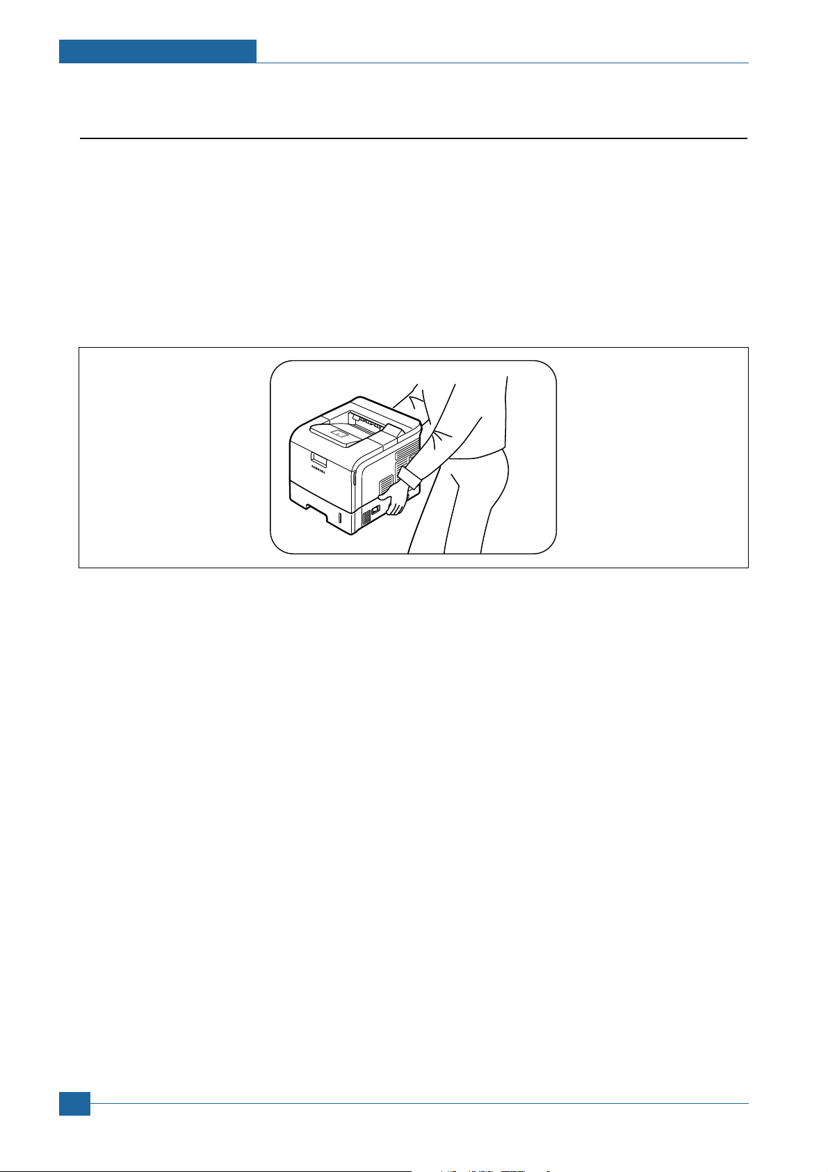
(3) When you move the printer.
This printer weighs 22kg including toner cartridge and cassette. Use safe lifting and handling techniques. Use
the lifting handles located on each side of the machine. Back injury could be caused if you do not lift carefully.
(4) Ensure the printer is installed safely.
The printer weighs 22Kg, ensure the printer is installed on a level surface, capable of supporting its weight.
Failure to do so could cause the printer to tip or fall possibly causing personal injury or damaging the printer.
(5) Do not install the printer on a sloping or unstable surface. After installation, double check that the printer is stable.
Service Manual
1-4
Samsung Electronics
Page 10

Precautions
1.3 ESD Precautions
Certain semiconductor devices can be easily damaged by static electricity. Such components are commonly called
“Electrostatically Sensitive (ES) Devices”, or ESDs. Examples of typical ESDs are: integrated circuits, some field
effect transistors, and semiconductor “chip” components.
The techniques outlined below should be followed to help reduce the incidence of component damage caused by
static electricity.
Caution >>Be sure no power is applied to the chassis or circuit, and observe all other safety precautions.
1. Immediately before handling a semiconductor component or semiconductor-equipped assembly, drain off any
electrostatic charge on your body by touching a known earth ground. Alternatively, employ a commercially available wrist strap device, which should be removed for your personal safety reasons prior to applying power to the
unit under test.
2. After removing an electrical assembly equipped with ESDs, place the assembly on a conductive surface, such as
aluminum or copper foil, or conductive foam, to prevent electrostatic charge buildup in the vicinity of the assembly.
3. Use only a grounded tip soldering iron to solder or desolder ESDs.
4. Use only an “anti-static” solder removal device. Some solder removal devices not classified as “anti-static” can
generate electrical charges sufficient to damage ESDs.
5. Do not use Freon-propelled chemicals. When sprayed, these can generate electrical charges sufficient to damage ESDs.
6. Do not remove a replacement ESD from its protective packaging until immediately before installing it. Most
replacement ESDs are packaged with all leads shorted together by conductive foam, aluminum foil, or a comparable conductive material.
7. Immediately before removing the protective shorting material from the leads of a replacement ESD, touch the protective material to the chassis or circuit assembly into which the device will be installed.
8. Maintain continuous electrical contact between the ESD and the assembly into which it will be installed, until completely plugged or soldered into the circuit.
9. Minimize bodily motions when handling unpackaged replacement ESDs. Normal motions, such as the brushing
together of clothing fabric and lifting one’s foot from a carpeted floor, can generate static electricity sufficient to
damage an ESD.
Samsung Electronics
Service Manual
1-5
Page 11
2. Product Specifications
2
2
2.1 Product Overview
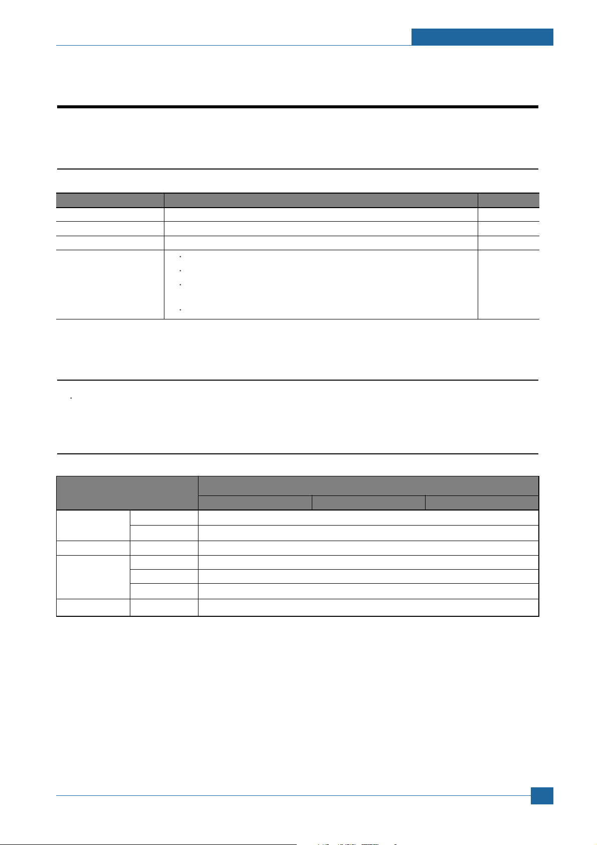
Item Descriptions Remark
Basic Model ML-4550
Series Model ML-4550, ML-4551N, ML-4551ND, ML-4551NDG(Kor.)
Maket of Sailes Office user Laser printer. (Network for work Group)
Specification
43ppm(Ltr. 45ppm), 500MHz Processor, 128MB Memory
10K(initial), 20K(sailes)
USB(Hight Speed USB 2.0), Network Option,
ML-4551N, ML-4551ND(Network base)
Face Down(250 sheets), Face Up(100 sheets)
Specifications
2.2 Specifications
Product Specifications are subject to without notice. See below for product specifications.
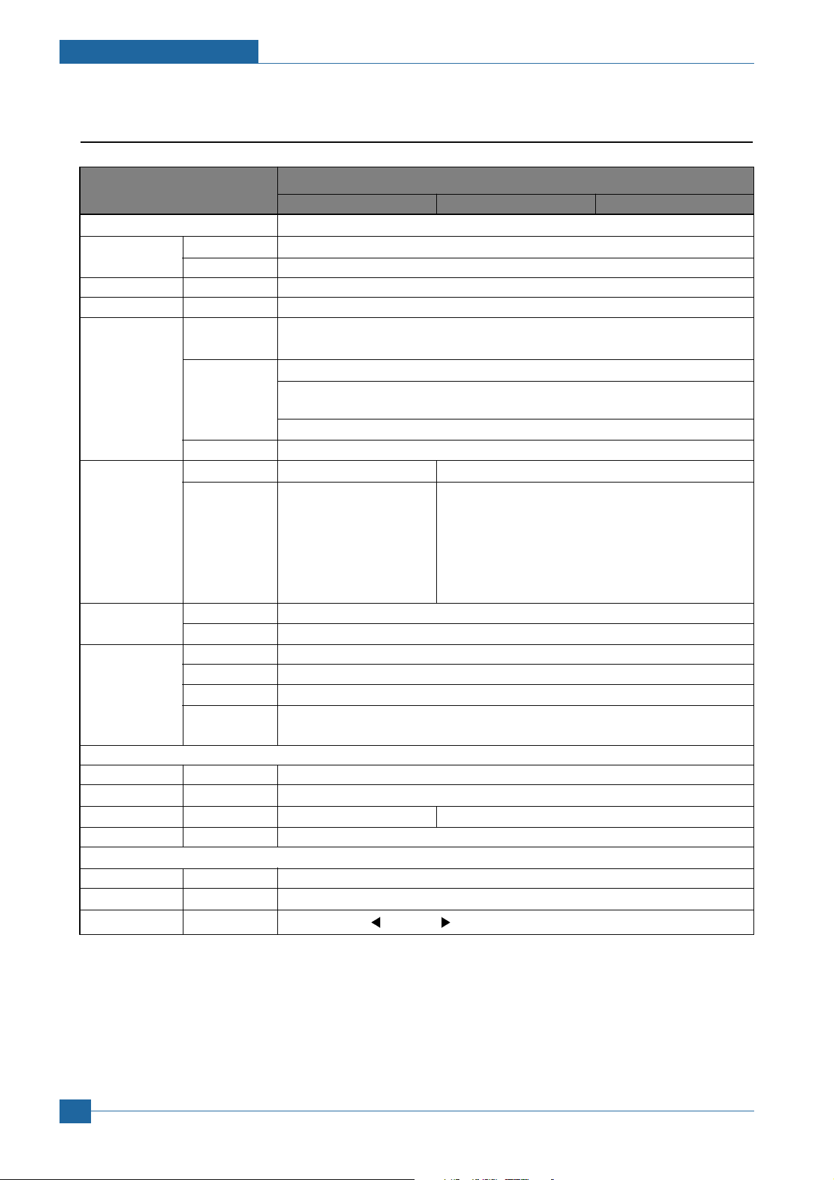
2.2.1 General Specifications
ITEM ML-4550 SERIES
ML-4550 ML-4551N ML-4551ND
Engine Speed Simplex Up to 43 ppm in A4 (45 ppm in Letter)
Duplex Option : 29 ipm in A4 (30 ipm in Letter)
Warmup time - Less than 45 sec : Power-on boot
FPOT From Ready Less than 8.5 sec
From Idle Less than 43.5 sec
From Coldboot
Resolution - Up to 1200 x 1200 dpi effective output
Less than 53.5 sec
Samsung Electronics
Service Manual
2-1
Page 12
Specifications
2.2.2. Controller & S/W
ITEM ML-4550 SERIES
ML-4550 ML-4551N ML-4551ND
Processor Marvell 500Mhz
Memory Std. 128 MB
Max. 512MB(256+256)
Printer Languages
Fonts - 45 scalable, 1 bitmap, 136 PostScript 3 fonts, OCR Fonts
Driver Default Driver PCL6 : Win 95/98/NT4.0/2000/Me/XP(32/64bits)/2003 Server(32/64bits)
Wired Network
Wireless Protocol N/A
Network
Application RCP N/A
Interface
Parallel - IEEE 1284
USB - High Speed USB 2.0
Wired Network
Wireless Network
User Interface
LCD - 16 x 12 Character LCD
LED - 2LED(Status LED, Save Button LED)
Key - 8 Key: Menu ,
- PostScript3, PCL6, IBM ProPrinter, EPSON, PDF Direct(only HDD installed)
PS : Linux & Mac
Supporting OS
Windows 95/98/NT4.0/2000/Me/XP(32/62bits)/2003 Server(32/62bits)
Various Linux OS including Red Hat 8~9, Fedora Core 1~3, Mandrake 9.2~10.1
and SuSE 8.2~9.2
Mac OS 8.6~9.2/10.1~10.4
WHQL Windows 2000, XP, 2003 Server
Protocol N/A SPX/IPX, TCP/IP, SNMP, HTTP 1.1, AppleTalk
Supporting OS
N/A Windows 98/ME/NT4.0/2000/XP(32/64bits)/2003
Server(32/64bits)
Netware 4.x, 5.x, 6.x
Mac OS 8.6~9.2, 10.1~10.4
Various Linux OS including Red Hat 8.0~9.2, Fedora
Core 1~3, Mandrake 9.2~10.1
and SuSE 8.2~9.2
Supporting OS
N/A
Status Monitor N/A
Smart Panel YES (Include RCP and SM)
Network N/A
Management
- Optional 10/100 Base TX
- N/A
, OK (*) , , Back Toner Save , Demo , Stop
Service Manual
2-2
Samsung Electronics
Page 13
Specifications
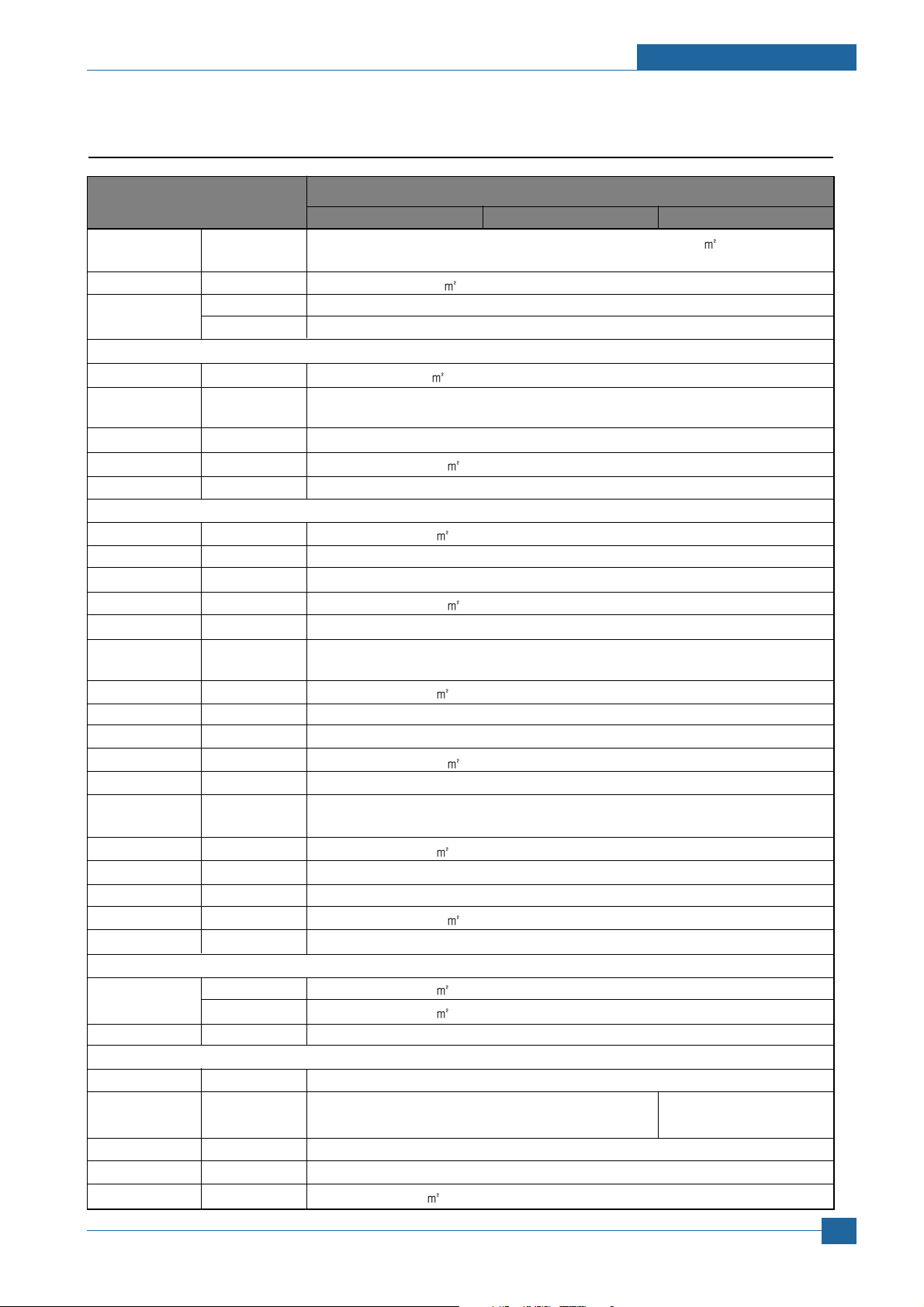
2.2.3. Paper Handling
ITEM ML-4550 SERIES
ML-4550 ML-4551N ML-4551ND
Standard - 500-sheet Cassette Tray, 100-sheet Multi Purpose Tray @75g/
Capacity
Max. Capacity - 2,100 sheets @75g/
Printing Max. Size 216 x 356 mm (8.5" x 14")
Min. Size 76 x 127 mm (3.0" x 5.0")(>105g)
Multi-purpose tray
Capacity - 100 sheets @75g/
Media sizes - A4, A5, A6, Letter, Legal, Oficio, Folio, Executive,ISO B5, JIS B5, 3"x5", Monarch,
No.10, DL, C5, C6
Media type - Transparencies, Envelopes, Labels, Card stock
Media weight - 16~43 lb (60 to176g/
Sensing - Paper empty sensor
Standard Cassette Tray
Capacity - 500 sheets @ 75g/
Media sizes - A4, A5, Letter, Legal, Executive, Folio, Oficio, ISO B5, JIS B5
Media types - Plain Paper
Media weight - 16~28lb (60 to 105g/
Sensing - Paper empty sensor, Paper Size Sensor
Second Optional
Cassette Tray
Capacity - 500 sheets @ 75g/
Media sizes - A4, A5, Letter, Legal, Executive, Folio, Oficio, ISO B5, JIS B5
Media types - Plain Paper
Media weight - 16~28lb (60 to 105g/
Sensing - Paper empty sensor, Paper Size Sensor
Third Optional
Cassette Tray
Capacity - 500 sheets @ 75g/
Media sizes - A4, A5, Letter, Legal, Executive, Folio, Oficio, ISO B5, JIS B5
Media types - Plain Paper
Media weight - 16~28lb (60 to 105g/
Sensing - Paper empty sensor, Paper Size Sensor
Output Stacking
Capacity Face-Down 250 sheets @ 75g/
Face-Up 100 sheets @ 75g/
Output Full sensing
- Paper full Sensor
Optional Stacker
Capacity Face-Down N/A
Duplex - Optional Built-in
Supporting
Media sizes - A4, Letter, Legal, Folio, Oficio
Media types - Plain Paper
Media weight - 20~24lb (75~90g/
Samsung Electronics
)
)
)
)
)
Service Manual
2-3
Page 14
Specifications
2.2.4. Consumables
ITEM ML-4550 SERIES
ML-4550 ML-4551N ML-4551ND
Toner Black Standard 10K pages @ ISO 19752 standard Coverage
High Yield 20K pages @ ISO 19752 standard Coverage
Key Electronic key(CRUM)
Life detect Toner remaining volume would be traced via software
Drum Yield Same as consumables
2.2.5. Reliability & Service
ITEM ML-4550 SERIES
ML-4550 ML-4551N ML-4551ND
Printing Volume
(SET AMPV)
Max. Monthly - 150,000 sheets
Duty
MPBF - 150,000 sheets
MTTR - 20 min.
SET Life Cycle - 500,000 sheets or 5 years (whichever comes first)
- 5,000 sheets / month
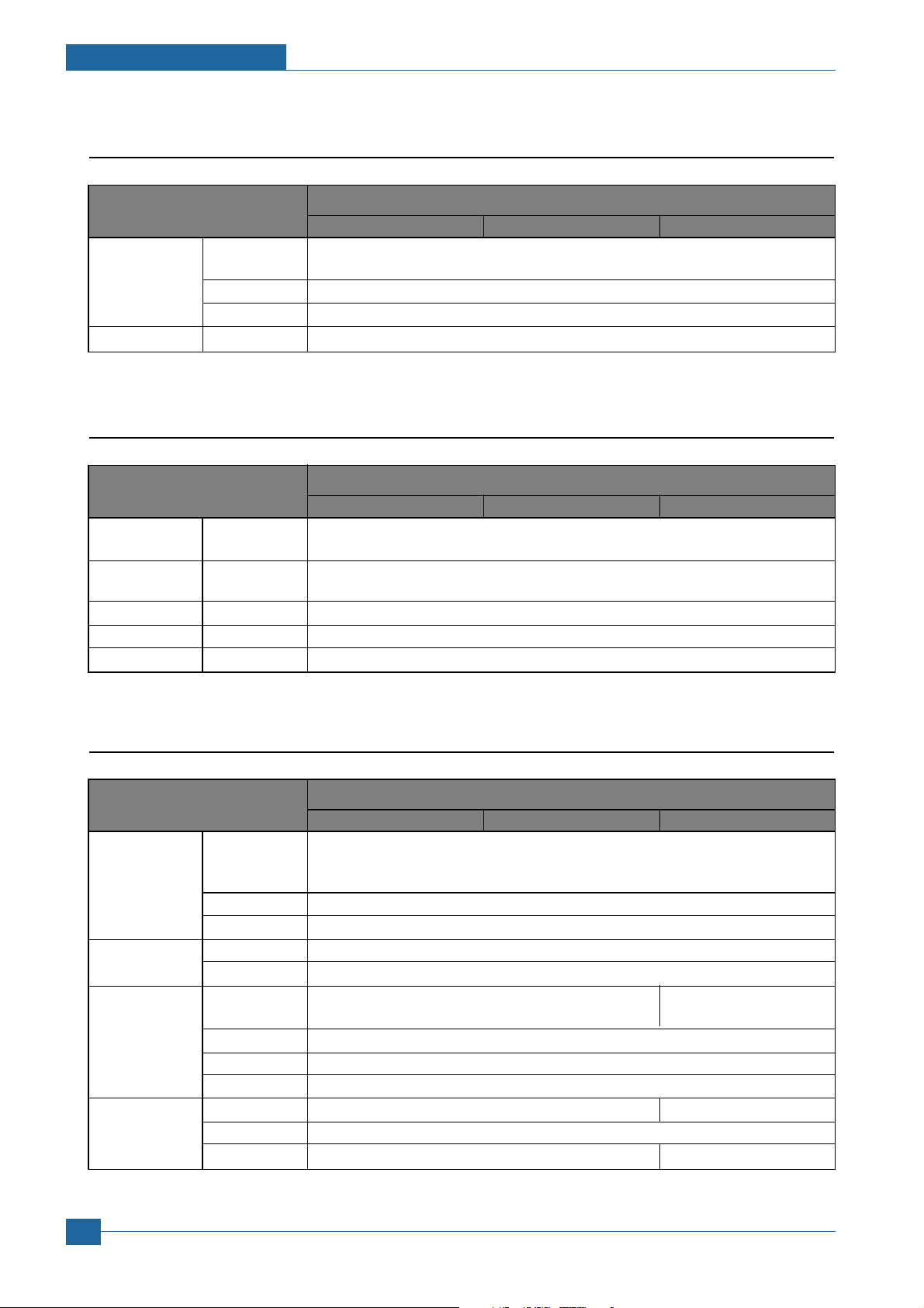
2.2.6. Environment
ITEM ML-4550 SERIES
ML-4550 ML-4551N ML-4551ND
Acoustic Noise
Level(Sound
Power/Pressure)
Power AVG. Less than 650W
Consumption
Dimension SET 396 x 453 x 353 mm (15.6" x 17.8" x 13.9") 396 x 501 x 353 mm
(W x D x H) (15.6" x 19.7" x 13.9")
Weight SET 17.8kg(39.2 Ib) 19.1kg
Printing Less than 57.0 dBA
Standby Less than 35.0 dBA
Sleep Back Ground Level
Sleep/Power Off
SET Packing 518 x 566 x 568 mm (External)
CRU 314 x 242 x 138 mm
Toner Packing
Toner(10K) 10K : 1.85kg(4.08 Ibs), 20K : 2.06kg(4.54 Ibs)
Gross 21.6kg(47.62 Ibs) 23.5kg(51.81 Ibs)
Less than 13W
370 x 286 x 180 mm (External)
Service Manual
2-4
Samsung Electronics
Page 15
2.2.7. Options
ITEM ML-4550 SERIES
ML-4550 ML-4551N ML-4551ND
Memory - 128MB/512MB (256MB+256MB)
Second Cassette
Third Cassette - 500 sheet Cassette Tray
Stacker - N/A
Stapler N/A
PostScript - Default
Wired Network
Hard Disk - 40GB
Duplex Unit - Optional Default
- 500 sheet Cassette Tray
- Ethernet 10/100 Base Default Default
TX (Internal)
Specifications
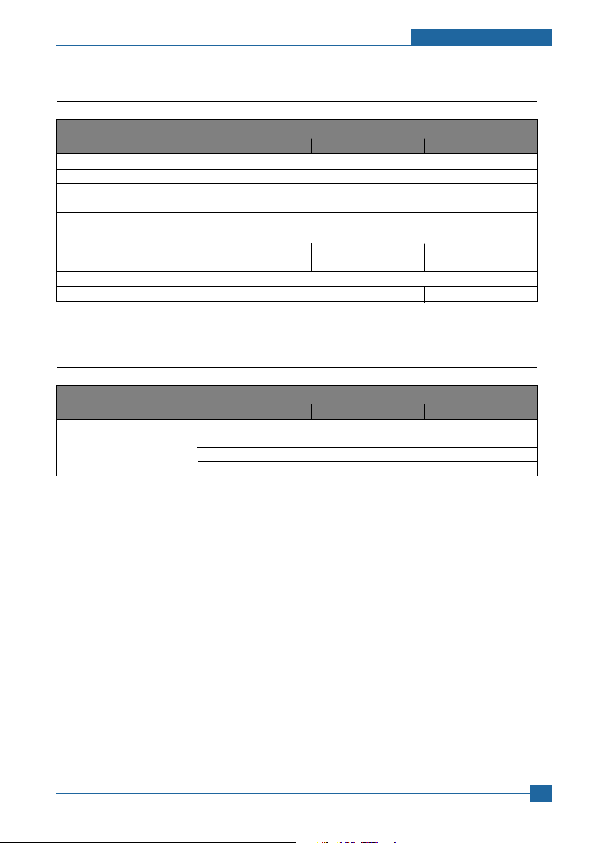
2.2.8. Others
ITEM ML-4550 SERIES
ML-4550 ML-4551N ML-4551ND
Performance Jam Rate Base Line Paper : 1/12K
Requirement
Standard Paper : 1/10K
Stress Paper : 1/1500
Samsung Electronics
Service Manual
2-5
Page 16
Specifications
Specifications
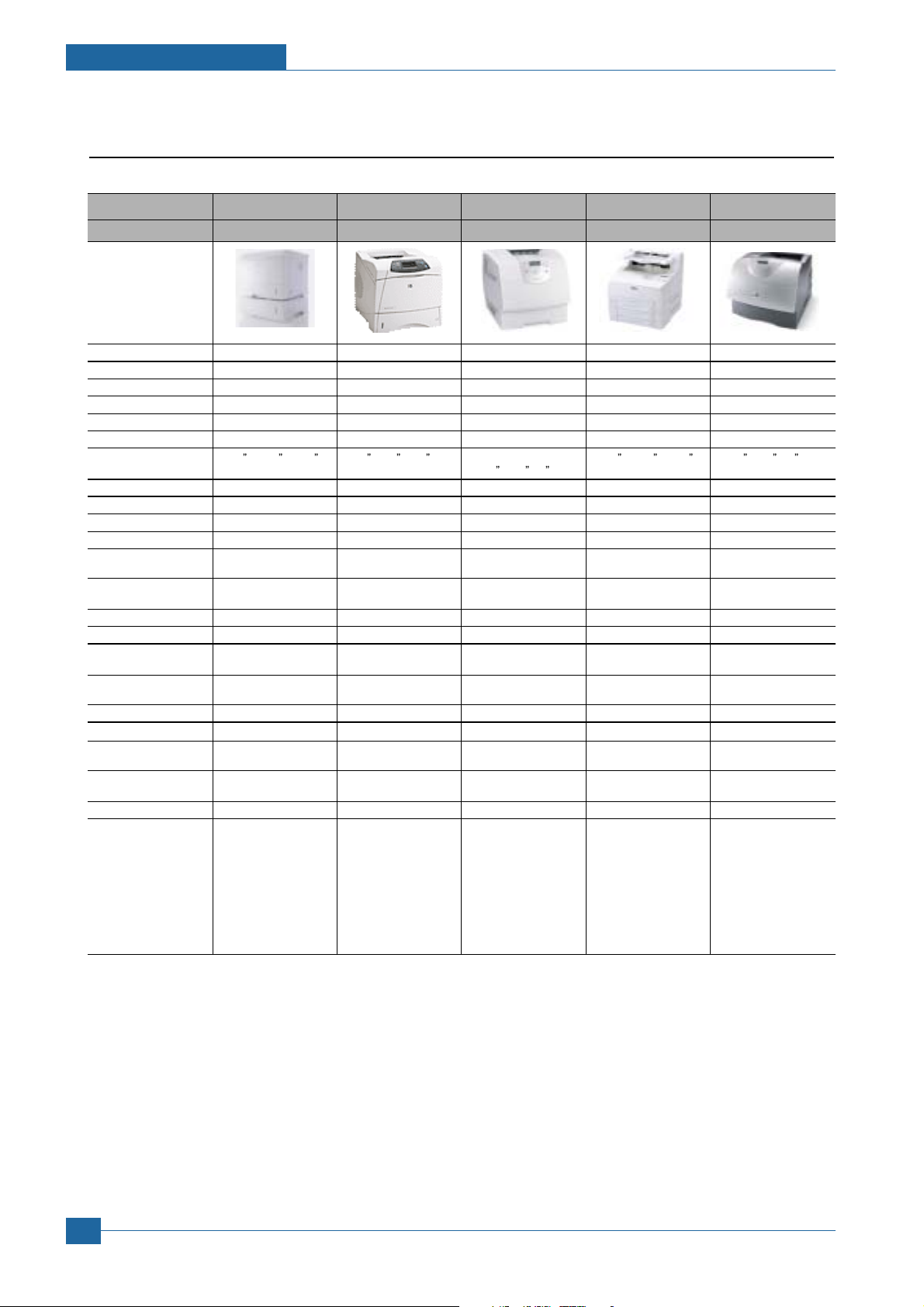
2.3 Model Comparison Table
Project SEC HP Lexmark Brother Dell
Model Name ML-4550 LJ-4250 T642 HL-8050N W5200N
Engine
FPOT 8.5 sec 8 sec 8.5 sec 9 sec 8.5 sec
Speed(ppm) 43ppm (Ltr. 45ppm) 43ppm (Ltr. 45ppm) 43ppm (Ltr. 45ppm) 34ppm (Ltr. 35ppm) 43ppm (Ltr. 45ppm)
Resolution 1200 dpi 1200 dpi 1200 dpi x 1200 dpi 1200dpi x 1200 dpi 1200 dpi x 1200 dpi
Noise(dB)
Weight 17.83kg 20.2kg (45 lbs) 23.1Kg (51lbs) 20.6Kg (45.2 lbs) 45lbs
Demension(W*D*H) 15.6
Control
Processor 500MHz 460MHz 457 MHz RISC 300MHz 500 MHz RISC
Ram(Std.) 128MB 48MB 64MB 64MB 80MB
Ram(Max.) 512MB 512MB 576MB 576MB 336MB
Emulation PCL6, PS3 PCL6, PS3 PCL6, PS3 PCL6, PS3, PCL6, PS3,
Interface IEEE1284, USB 2.0 IEEE1284, USB 2.0 IEEE1284, USB 1.1 IEEE1284, USB IEEE1284, USB
Optional Interface 10/100 Base TX 10/100 Base TX 10/100 Base TX N/A N/A
Paper Handling
Paper Input(Capa./Type)
Paper Output 250 Sheets Face down 250 Sheets Face down 500 Sheets Face Down 500 Sheet Face down 250 Sheets Face Down
Others
Max.Monthly Duty 150,000 sheets 200,000 sheets 225,000 sheets - 225,000 sheets
Consumable Yeild Standard 10K Standard 10K Standard 6K 17K Standard 18K
Power Consumption
Duplex Option Option Option Option NO
Options
57dB(Printing), 35dB(Idle)
x 17.8 x 13.9 16.5 x17.8 x14.8 436x523x406mm 16.6 x 18.3 x 15.9 (17.2 x20.2 x16 )
396 x 453 x 353 mm 418x451x377mm (17.2
500 Sheets 500 Sheets 500 Sheets 550 Sheets Cassette 500 Sheets
Cassette100 MP Tray Cassette100 MP Tray Cassette100 MP Tray 150 Sheets Cassette Cassette100 MP Tray
100 Sheets Face up 70 Sheet Face up
High Yield 20K High Yield 20K High Yield 21K High Yield 27K
Printing : Less than 650 W
Sleep : under 13 W Sleep : under 20 W Sleep:< 12W
- Memory (128MB/256MB)
- 3x500 sheet SCF - 500 sheet SCF - 3x250 sh drawer - Memory - 85 envelope
- Duplex - Duplex
- 40GB HD - HP Jetdirect
not_inform
Printing : 680 W not_inform Printing: < 593W not_inform
- Memory - 250 sh duplexer - SCF - duplexer
- 20GB HD
- Stacker & Stapler
55dB(Printing), 30dB(Idle) 54dB(Printing), 27dB(Idle) 55dB(Printing),
x20.6 x16 )
10/100 Base TX 10/100 Base TX
2.010/100 Base TX 2.010/100 Base TX
- 2000 sh drawer(Max.3850)
- 85 sh envelope feeder
- 650 sh output expander
- 1850 sh High capacity
output stacker
- 40 sheet staple
- 5 bin mailbox
(5x120 sh )
- Stand feeder
- Sorter/Mail box - 500 sheet cassette
- 250 sheet cassette
34dB(Idle)
Service Manual
2
2-6
Samsung Electronics
Samsung Electronics
Page 17

ACCE
SSORY
em
C
y
Specifications
It
INA-ACCESSORY
CBF-POWER CORD
BAG PE
S/W APPLICATION-CD
S/W APPLICATION-CD
MANUAL-(CARD)WARRANTY CARD
MANUAL-NETWORK GUIDE
LABEL(P)-BLANK 90*25
ode
JC99-01974E
3903-000042
6902-000288
JC46-00280A
JC46-00293A
JC68-00690A
JC68-01579A
JC68-01584A
Quantit
Samsung Electronics
Service Manual
2-7
Page 18
3. Summary of Product
This chapter describes the functions and operating principal of the main component.
3
3
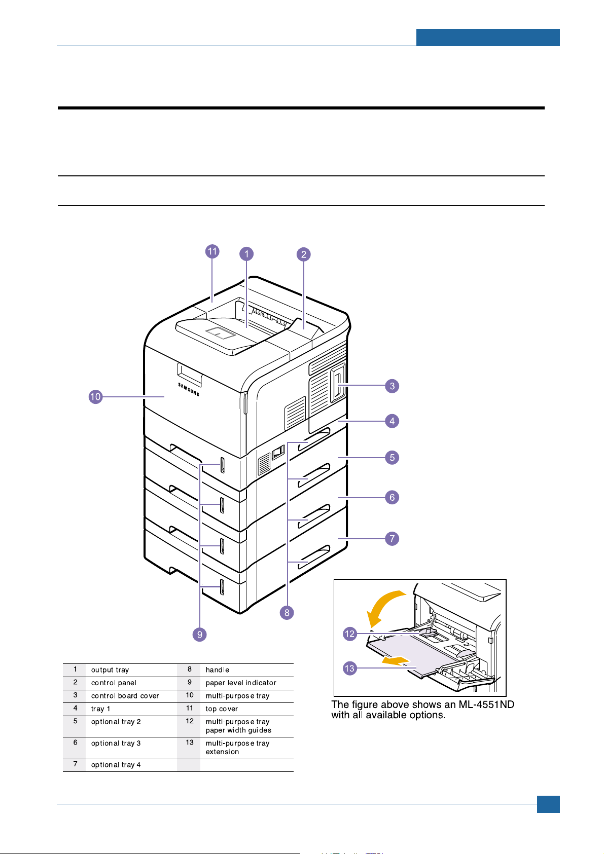
3.1 Printer Components
3.1.1 Front View
Summary of Product
Samsung Electronics
Service Manual
3-1
Page 19
Summary of Product
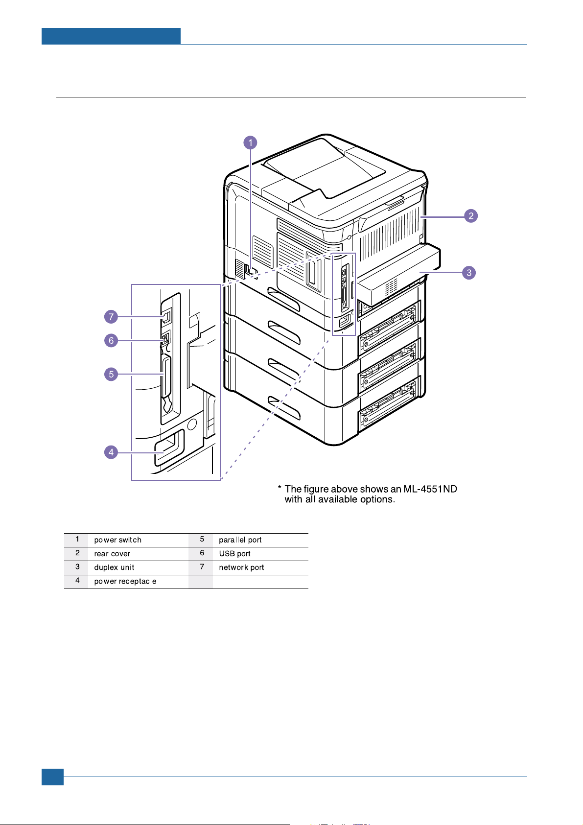
3.1.2 Rear View
Service Manual
3-2
Samsung Electronics
Page 20
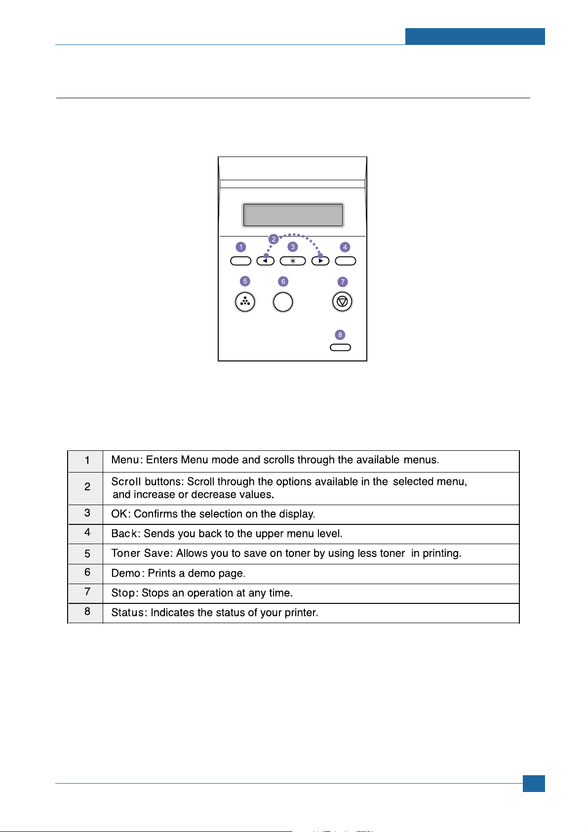
3.1.3 Control Panel
The control panel on the top right side of your printer has the display and the nine buttons.
Summary of Product
3.1.3.1 Display
Samsung Electronics
Service Manual
3-3
Page 21
Summary of Product
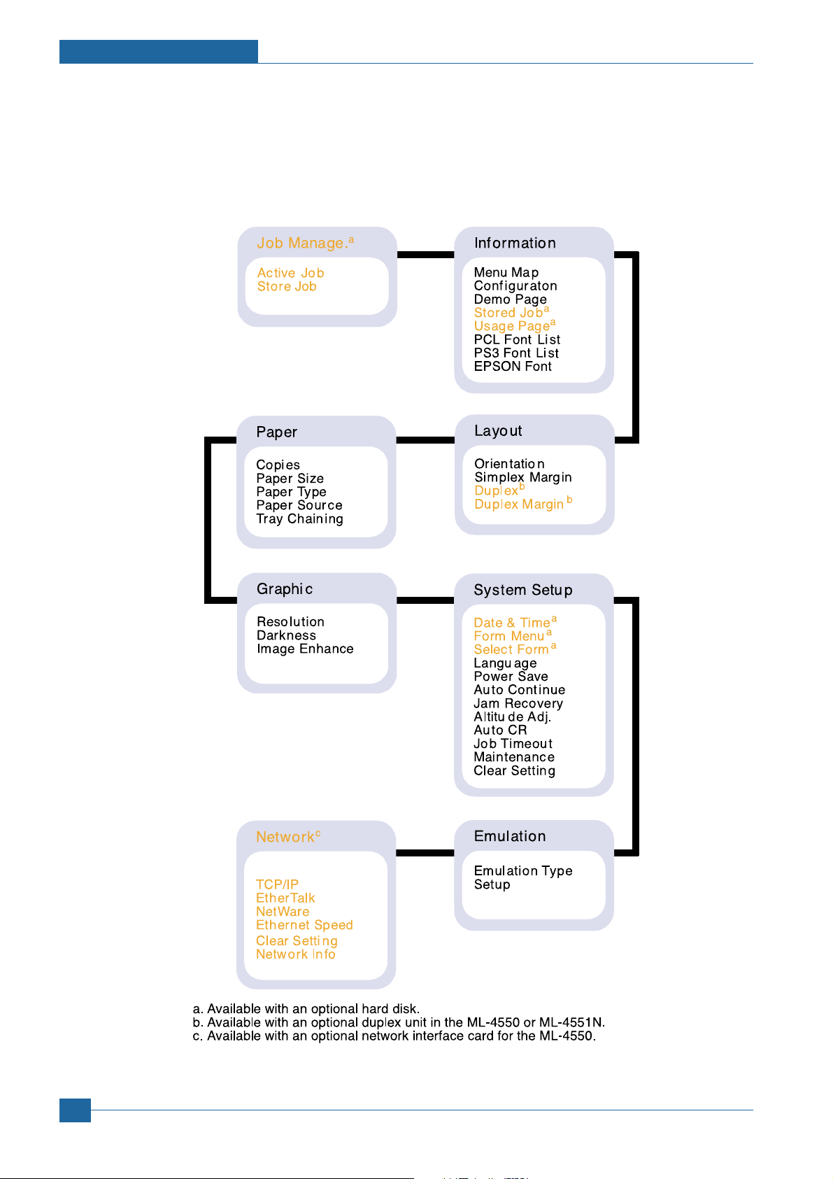
3.1.3.2 Overview of Control Panel Menus
The control panel menus are used to configure the printer for your environment.
The control panel provides access to the following menus.
Service Manual
3-4
Samsung Electronics
Page 22
Summary of Product
1 2
3 4
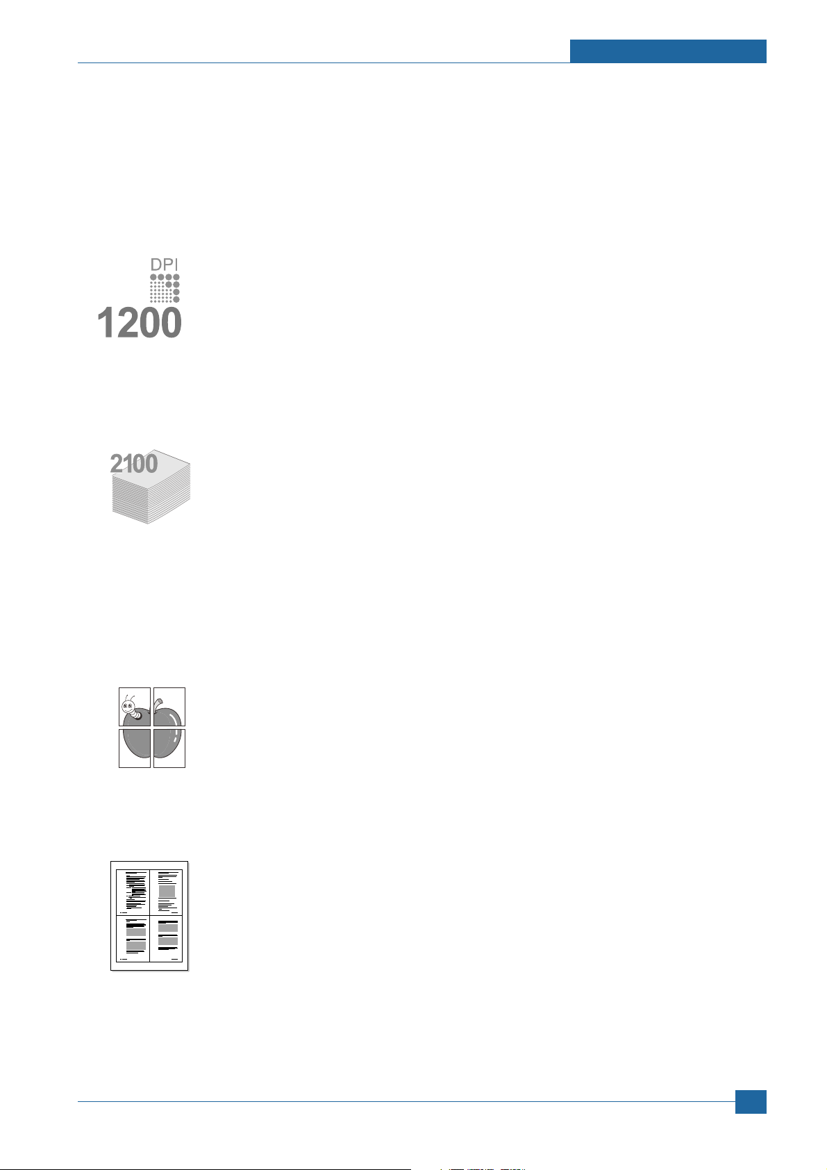
3.1.3.3 Special Features
Your new printer is equipped with special features that improve the print quality,giving you a competitive edge.
You can:
Print with excellent quality and high speed
• You can print up to 1200 x 1200 dpi effective output. See the Software Section.
• Your printer prints A4-sized paper at up to 43 ppm a and letter-sized paper at up to 45
ppm. For duplex printing, your printer prints A4-sized paper at up to 29 ipm b and lettersized paper at up to 30 ipm.
Handle paper flexibly
• The multi-purpose tray supports letterheads, envelopes, labels, transparencies, customsized materials, postcards, and heavy paper. The multi-purpose tray holds up to 100
sheets of plain paper.
• The 500-sheet standard tray 1 supports plain paper in various sizes.
• The 500-sheet optional tray support plain paper in various sizes. You can install up to 3
additional trays.
• Two output tray; select either the output tray (face-down) or the rear cover (face-up) for the
most convenient access.
• Straight-through paper path capability from the multi-purpose tray to the rear cover.
Create professional documents
• Print Watermarks. You can customize your documents with words, such as “Confidential.”
See the Software Section.
• Print Posters. The text and pictures of each page of your document are magnified and
printed across the sheet of paper and can then be taped together to form a poster. See
the Software Section.
a. pages per minute
b. images per minute
Save your time and money
• This printer allows you to use toner save mode to save toner.
• You can print on both sides of the paper to save paper (double-sided printing) if you use
the ML-4551ND or install the optional duplex unit in the ML-4550 and ML-4551N.
• You can print multiple pages on a single sheet of paper to save paper (N-Up printing). See
the Software Section.
• You can use preprinted forms and letterhead with plain paper. See the Software Section.
• This printer automatically conserves electricity by substantially reducing power consumption when not in use.
Samsung Electronics
Service Manual
3-5
Page 23

Summary of Product
Expand the printer capacity
• Your printer has 128 MB of memory which can be expanded to 512 MB.
• A Network interface enables network printing. You can add an optional network interface
card to the ML-4550. The ML-4551N and ML-4551ND come with a built-in network
interface, 10/100 Base TX.
• You can add 500-sheet optional trays to your printer. These trays let you add paper to the
printer less often.
• A PostScript 3 Emulation* (PS) enables PS printing.
Use the optional hard disk
You can install an optional hard disk in your printer.
• The 40 GB hard disk can store the data from your computer in the print queue. This decreases the workload of the
computer.
• You can use various print features, such as storing a job in the hard disk, proofing a job, and printing private documents.
• You can manage the print jobs in the print queue of the printer hard disk. For details.
Print in various environments
• You can print in Windows 98/Me/NT 4.0/2000/XP/2003.
• Your printer is compatible with Linux and Macintosh.
• Your printer comes with both Parallel and USB interfaces.
• You can also use a network interface. The ML-4551N and ML-4551ND come with a built-in network interface, 10/100
Base TX. However, you need to install the optional wired network interface card to the ML-4550.
Printer Features
The table below lists a general overview of features supported by your printer.
(I: Installed, O: Option)
Features ML-4550 ML-4551N ML-4551ND
IEEE 1284 Parallel I I I
USB 2.0 I I I
Network Interface O I I
(Ethernet 10/100 Base TX)
Hard Disk O O O
PostScript* Emulation I I I
Duplex Unit O O I
Optional Tray 2 O O O
Optional Tray 3 O O O
Optional Tray 4 O O O
Service Manual
3-6
Samsung Electronics
Page 24
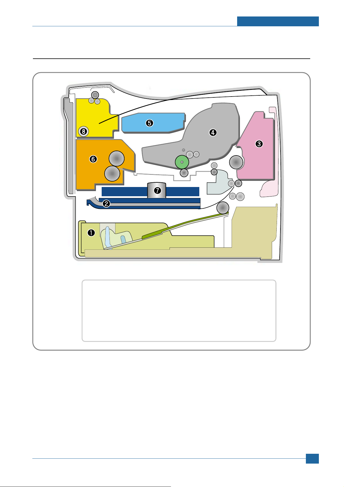
3.2 System Layout
❶ Cassette ❷ Duplex
❸ MPF ❹ Print Cartridge
❺ LSU ❻ Fuser
❼ SMPS & HVPS Board ❽ Duplex Solenoid
Summary of Product
Samsung Electronics
Service Manual
3-7
Page 25

Summary of Product
3.2.1 Feeding
It is consists of a basic cassette, an MP tray for supplying different types of media : envelope, label special paper, duplex unit, and parts related to paper transferring.
1) Separation method
Separate it from the friction pad mounted to the center of the cassette and apply retard roller that
uses a spring clutch. A feed roller uses an electronic clutch to control driving power.
2) Basic cassette
It takes a center loading method and applies 'friction pad separating method.' It means that there is
a paper sensor, but a paper size is detected after detecting the first paper by software.
Both the side guide and the rear guide can be adjusted for for various types of papers from A5 to
legal size paper.
It has a paper existence sensing function (Capacity: 500 sheets of general paper), paper arranging
function, various size papers accepting function, SCF paper path function, and displaying function
of paper remaining amount.
In the front side, there is a paper level indicator.
3) Pick-up roller
It has functions such as a paper pickup function, driving control function, paper feeding function,
and removing electronic static function.
4) Retard roller
It takes an arrangement method which uses a stopper roller and a weight without electric actuator.
It has paper separating function, driving control function, and multi feeding prevention function.
6) Registration roller
It has a paper arranging function, paper transferring function, paper detecting function, jam removing function, and so on.
7) MP tray
It has a paper arranging function, paper transferring function, jam removing function, and so on.
It uses rubbing pad method to feed 100 sheets of general papers and 10 envelops.
It is possible to extend to 300mm for accepting a legal size paper.
8) Duplex unit
It has paper transferring function, paper guide function, jam removing function, paper sensing function, and main board supporting function.
It is designed for basic attachment, and the duplex feeding takes a side feeding method. Usable
papers are A4, letter, and legal size paper.
For removing a jam occurred in a front part, it is designed to open a cassette and a guide.
It is designed to open a rear cover to remove a jam in a rear part.
If a face up tray is open, the duplex option cannot be used.
9) SCF (Second Cassette Feeder)
It is the same method with the main cassette, and the capacity is 500 sheets.
It has a separate driving mechanism. It is designed for a common use with a main cassette.
Service Manual
3-8
Samsung Electronics
Page 26

Summary of Product
3.2.2 Transfer
It consists of a PTL (Pre-transfer Lamp) and a transfer roller. A PTL sheds light on an OPC drum, lowers
an electric potential of an OPC drum's surface, and improves the efficiency of the transfer.
A transfer roller transfers toner on an OPC drum to the paper.
Life span: Print over 150,000 sheets (In 16~27
)
3.2.3 Driver Ass'y
By driving the motor, the system takes power. It consists of a main motor for feeding fuser and duplex
reverse turn, and a deve-motor for a toner cartridge.
- Main Motor : DC 24V, Rated RPM : 1604rpm
- Deve Motor : DC 24V, Rated RPM : 1424 rpm
3.2.4 Fuser
It is consisted of a heat lamp, heat roller, pressure roller, thermistor and thermostat. It sticks the toner on
a paper by heat and pressure to complete the printing job.
- E-coil Heator : 1,300 Watt
50W
1) Thermostat
When a heat lamp is overheated, a Thermostat cuts off the main power to prevent over-heating.
- Non-Cotact type Thermostat
3) Heat roller
The heat roller transfers the heat from the e-coil to apply a heat on the paper. The surface of a
heat roller is coated with Teflon, so toner does not stick to the surface.
4) Pressure roller
A pressure roller mounted under a heat roller is made of a silicon resin, and the surface also is
coated with Teflon. When a paper passes between a heat roller and a pressure roller, toner
adheres to the surface of a paper permanently.
5) Items for safety
Protecting device for overheating
- 1st protection device: Hardware cuts off when overheated
- 2nd protection device: Software cuts off when overheated
- 3rd protection device: Thermostat cuts off main power.
Safety device
- A fuser power is cut off when a front cover is opened
- Maintain a temperature of fuser cover's surface under 80(C for user, and attach a caution
label at where customer can see easily when customer open a rear cover.
3.2.5 LSU (Laser Scanner Unit)
It is the core part of the LBP which switches from the video data received to the controller to the electrostatic latent image on the OPC drum by controlling laser beam, exposing OPC drum, and turning principle
of polygon mirror. The OPC drum is turned with the paper feeding speed. The /HSYNC signal is created
when the laser beam from LSU reaches the end of the polygon mirror, and the signal is sent to the controller. The controller detects the /HSYNC signal to adjust the vertical line of the image on paper. In other
words, after the /HSYNC signal is detected, the image data is sent to the LSU to adjust the left margin on
paper. The one side of the polygon mirror is one line for scanning.
Service Manual
Samsung Electronics
3-9
Page 27
Summary of Product
Cleaning Roller
Cleaning Blade
-650V
200V
-1.30KV
V
PP = 1500V, f = 3.0KHz
1
2
3
4
5
6
7
8
+5.0kV
-50V
+
-
200V
+
-
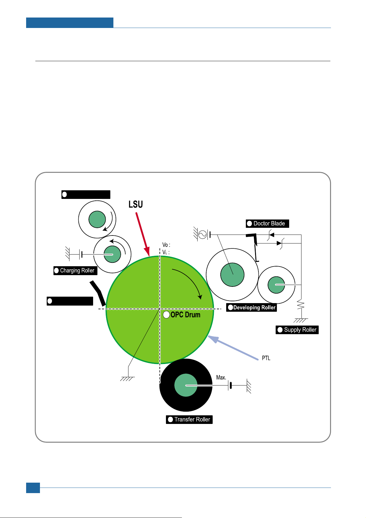
3.2.6 Print Cartridge
By using the electronic photo process, it creates a visual image. In the print cartridge, the OPC unit and
the toner cartridge unit are in a body. The OPC unit has OPC drum and charging roller, and the toner
cartridge unit has toner, supply roller, developing roller, and blade (Doctor blade)
- Developing Method: Non-contacting method
- Toner : Non magnetic 1 component pulverized type toner
- The life span of toner : 10,000 or 20,000 pages (LSA Pattern/A4 standard)
- Toner remaining amount detecting sensor : Yes
- OPC Cleaning : Cleaning blade type
- Management of disusable toner : Collect the toner by using Cleaning Blade
- OPC Drum protecting Shutter : Yes
- Classifying device for toner cartridge : ID is classified by CRUM.
Service Manual
3-10
<Toner Cartridge Layout>
Samsung Electronics
Page 28
Summary of Product
3.3 Engine H/W Specifications
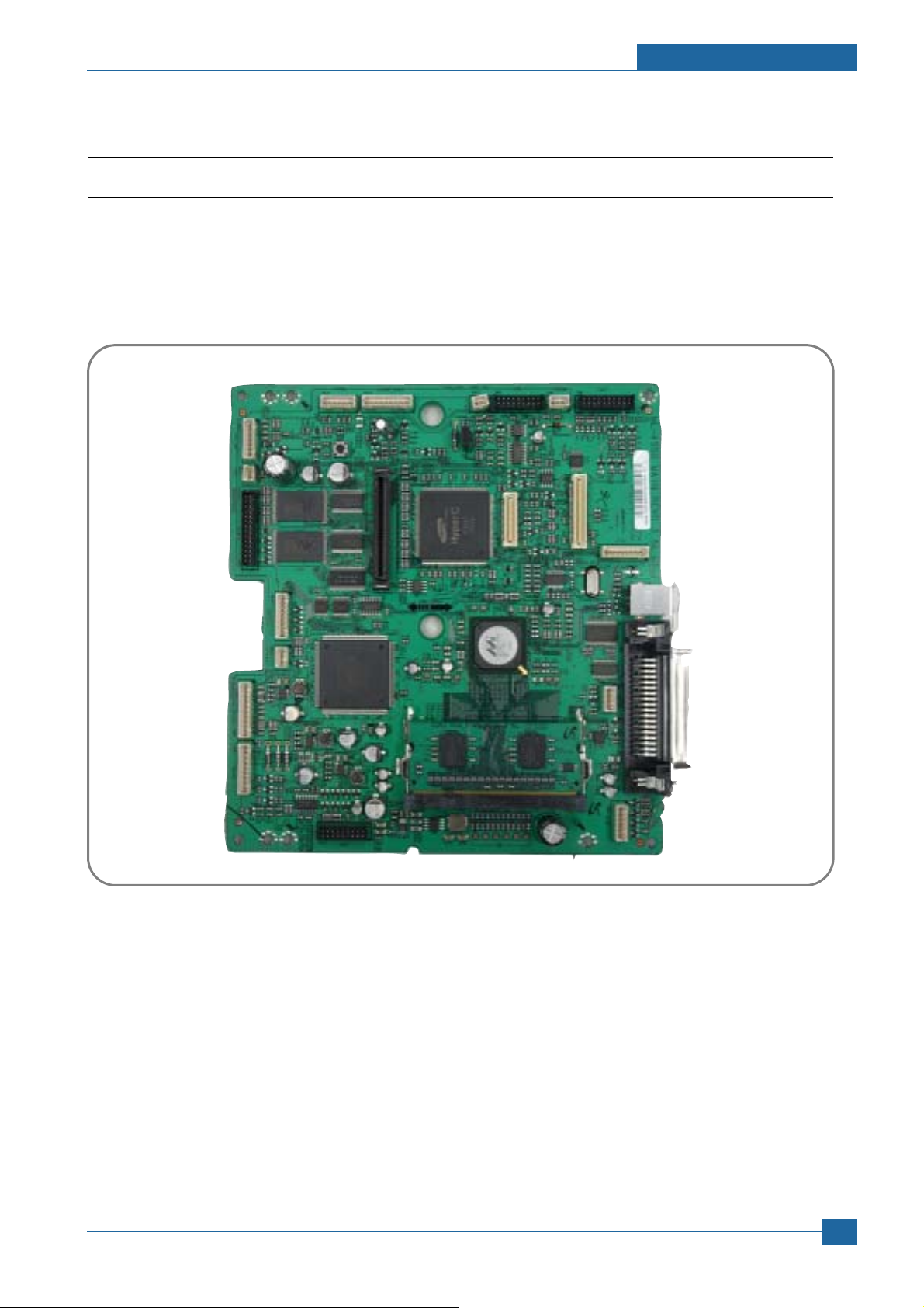
3.3.1 ML-4550 (PCL) Main Board
The Engine Board and the Controller Board are in one united board, and it is consisted of CPU part and print part in functional aspect. The CPU is functioned as the bus control, O/O handling, drivers, and PC interface. The main board sends
the Current Image by Video data to the LSU and manages the conduct of Electrophotography for printing. It is consisted
of the circuits of the motor (paper feed, pass) driving, clutch driving, pre-transfer lamp driving, current driving, and fan driving.
The signals from the paper feed jam sensor and paper empty sensor are directly inputted to the main board.
Samsung Electronics
Service Manual
3-11
Page 29

Summary of Product
3.3.1.1 Asic (ORION 2)
Marvell Feroceon 2850 ARM Compatoble (I-Cache: 32KB, D-Cache-32KB)
64-bit RISC embedded processor core
Dual bus architecture for bus traffic distribution
- AMBA High performance Bus (AHB)
- System Bus with SDRAM
- 64-bit Mbus Crossbar extension Interface with Flash and Device port
SDRAMC
- 32 Bits Dual mode DDR-II, 200MHz
- 4 Banks (Up to 256MB per Bank)
Device Controller
- Boot Flash 1 Bank (Up to 128MB)
- Device/NOR Flash 3 Banks (Up to 128MB per Bank)
No Graphic Execution Unit and Image processor
No Codec (Encoding / Decoding)
Printer Video Controller Interface for LBP engines
- Hyper-C : Printer Video Controller with RET algorithm
(Line Memory & Lookup Table Memory : 512 x 8 , 4096 x 16)
Dual / Single Beam, LVDS Pad (VDO, HSYNC)
PCI Controller
- 32Bits, 66MHz (PCI) / 133MHz (PCI-X)
- PCI Local Bus Specification rev. 2.2 compliant
- PCI Express Specification beta 1.0a compliant
- Host /Agent Mode (Support 3+4 Express Devices in Host Mode)
Engine Controller (LPEC1)
- LSU Interface unit
- Step Motor: 2 Channels
- PWM: 8 Channels
- ADC: 6 Channels
USB 2.0 Interface with Embedded USB 2.0 PHY
Gigabit Ethernet Controller
- IEEE 802.3 compliant with 10/100/1000 Mbps full-duplex GbE port
- Support GMII,MII and RGMII interface with external PHY/SERDES device
Package : 496pins PBGA
Power : 1.2V(Core), 3.3V(IO) power operation
Speed : 600MHz core(ARM9 Compatible) operation, 200MHz bus operation
Service Manual
3-12
Samsung Electronics
Page 30

Summary of Product
3.3.1.2 Memory
NOR Flash Memory : It stores System Program and downloads the System Program through PC Interface, and in
case of model for export it compresses the PCL font, then stores it.
- Capacity : 128M Byte
- Access Time : 70 nsec
DDR SDRAM : It is used as Swath Buffer, System Working Memory Area, etc. when printing.
It stores Font List, compressed into Flash memory, on DRAM and uses it as PCL font in case of model for export.
- Capacity : 128 Byte(Basic), up to 512Mbyte (User Option)
- Type : DDR-II SDRAM 200MHz , 32bit
3.3.1.3 Others
The Option PBA can be mounted for supporting the serial communication.
Samsung Electronics
Service Manual
3-13
Page 31

Summary of Product
Dual Channel
32 bit up to 200 MHz
DDR1/DDR2
SDRAM Controller
Feroceon CPU
32 KB
L1
Dcache
32 KB
L1
Icache
PCI/PCI-X
64-bit
port
Mbus-L to
Mbus
Bridge
Mbus ? Crossbar extension)
64 bit @ 166 MHz
GPPs,
UART x 2,
TWSI,
Flash
PCI-
Express
x 1 port
Gigabit
Ethernet
port
USB 2.0
port
Local bus ? 4 bit up to 200 MHz
3.3.1.4. 88F5281 Internal Block Diagram
Service Manual
3-14
Samsung Electronics
Page 32

Summary of Product
3.3.1.5 Sensor Input Circuit
3.3.1.5.1 Paper Empty Sensing
The Paper empty sensor (Photo Interruptor) on the engine board informs the state of paper to CPU whether it is empty
or not with operation of the actuator.
When cassette is empty, it detects the fact by reading the D0 Bit of CPU, and then informs the fact by selecting the second LED(yellow) among the panel LEDs.
3.3.1.5.2 MP Sensing
By operation of Actuator on the frame, MP Sensor (Photo interruptor) on the engine board informs the state of paper to
CPU whether it is empty or not. It reads the D0 Bit of CPU for recognizing paper in MP, and paper is fed from MP if there
is.
3.3.1.5.3 Paper Feeding/Width Toner Cartridge Sensing
When paper passes the actuator (feed sensor part), it detects the signal of Photo interrupter, informs the paper feeding
state to CPU, and then sprays the image data after certain time.
If it doesn’t detect the feed sensor within 1sec. after paper is fed, paper Jam0 (CPU #_ ) is occurred (Red and Yellow will
be turned on among the OP panel LEDs), and the fact whether the developer is inserted or not is detected with the
same principle. After the developer is mounted, the actuator is operated. The signal from the photo interrupter is detected
when it is passing the actuator of the sensor part. That is the developer ID sensing.
3.3.1.5.4 Paper Exit Sensing
It detects paper state whether paper gets out from the set with operation of exit sensor on the engine board and actuator
on the frame. Paper detects the on/off time of exit sensor by reading D2 Bit of CPU, and the normal operation or jam
information is informed to the CPU.
The paper JAM2 is informed. (Red, Yellow LED will be turned on among the OP panel LEDs)
3.3.1.5.5 Cover Open Sensing
The Cover open sensor is located on the front cover. After the front cover is opened, +24V (DC fan, Solenoid, Main
Motor, Polygon motor part of LSU and HVPS), which is supplied to the each unit, is cut off. The cover-open sensing is
operated by the D0 bit of CPU, and the developer ID sensing is operated by D7 bit of CPU.
In case, the red LED among OP pnael LEDs will be ON for informing the facts to user.
3.3.1.5.6 DC FAN / SOLENOID Driving
It is driven by transistor and controlled by D6 bit of CPU.
When it is high, the fan is driving by turning on the TR, and it is off when the sleep mode is selected. There are two solenoids, and they are driven by paper pick-up and MP signal. It is turned on or off by D4 bit of CPU, and its driving time is
300ms. The diode protects the driving TR from the noise pulse, which is flown when the solenoid id de-energizing.
FAN Driving Circuit is driven by Transistor, and controlled by D6 Bit of
3.3.1.5.7 Motor Driving
The motor driving circuit is formed when the Driver IC is selected in the first place. The A3977 Motor Driver IC is used in
this case. But resistance Rs value of sensing and voltage value of the V reference can be changed by motor driving voltage value. The motor driving voltage is calculated with the following formula.
I = Vref / Rs, wherein Vref is (R1x 5V) / (R1+R2).
Samsung Electronics
Service Manual
3-15
Page 33

Summary of Product
SMPS
HVPS
3.3.2 SMPS & HVPS board
Outputs 5V, 24V to supply the power to the main board and Optional Board(SCF, Duplex) (Not ADF Board)
Service Manual
3-16
Samsung Electronics
Page 34

Summary of Product
3.3.2.1 HVPS (High Voltage Power Supply)
• Transfer High Voltage (THV+)
- Input Voltage : 24 V DC
- Output Voltage : MAX +5.0KV
-1.2KV
15% (when cleaning, 200 )
- Output Voltage Trigger : 6.5
- Input contrast of the Voltage stability degree :under 5 % (fluctuating input 21.6V ~ 26.4V)
Loading contrast :
- Output Voltage Rising Time : 100 ms Max
- Output Voltage Falling Time : 100 ms Max
- Fluctuating transfer voltage with environmental various : +650 V(Duty 10%) ~ 5 KV (Duty 90%)
- Environment Recognition Control Method : The THV-PWM ACTIVE is transfer active signal. It detects the resistance
by recognizing the voltage value, F/B, while permits the environmental recognition voltage.
- Output Voltage Control Method : Transfer Output Voltage is outputted and controlled by changing Duty of THVPWM
Signal. 10% Duty : +650V, 90%
Duty : +5KV
5%
15%
5 %,(Duty Variable, no loading )
5 % or less
Fuser Voltage
- Input Voltage : 24 V DC
- Output Voltage : 30V~1000V DC
15%
30V
- Output Voltage Rising Time : 50 ms Max
- Output Voltage Falling Time : 50 ms Max
- Output Loading range : 30 M
~ 1000 M
- Output Control Signal(MHV-PWM) : CPU is HV output when PWM is Low
Cleaning Voltage (THV-)
- The (+) Transfer Voltage is not outputted because the THV PWM is controlled with high.
- The (-) Transfer Voltage is outputted because the THV-Enable Signal is controlled with low
- The output fluctuation range is big because there is no Feedback control.
Developing Voltage (DEV)
- Input Voltage : 24 V DC
- Output Voltage: -200V ~ -600V DC
15%
20V
- Output Voltage Fluctuation range: PWM Control
- Input contrast of the output stability degree :
Loading contrast :
5 % or less
5 % or less
- Output Voltage Rising Time : 50 ms Max
- Output Voltage Falling Time : 50 ms Max
- Output Loading range : 10M
~ 1000 M
- Output Control Signal (BIAS-PWM) : the CPU output is HV output when PWM is low.
Supply
- Output Voltage : -400V~ -800V DC
- Input contrast of the output stability degree : under
Loading contrast :
5 % or less
50V(ZENER using, DEV )
5 %
- Output Voltage Rising Time : 50 ms Max
- Output Voltage Falling Time : 50 ms Max
- Output Loading range : 10 M
~ 1000 M
- Output Control Signal (BIAS-PWM) : the CPU is HV output when PWM is low.
Samsung Electronics
Service Manual
3-17
Page 35

Summary of Product
3.3.2.2 SMPS (Switching Mode Power Supply)
It is the power source of entire system. It is assembled by an independent module, so it is possible to use for common use.
It is mounted at the bottom of the set.
It is consisted of the AMPS part, which supplies the DC power for driving the system, and the AC heater control part, which
supplies the power to fuser. SMPS has two output channels. Which are 3.3V and +24V.
• AC Input
- Input Rated Voltage : AC 220V ~ 240V AC 120V / AC 220V(EXP version)
- Input Voltage fluctuating range : AC 198V ~ 264V AC 90V ~ 135V / AC 198V ~ 264V (EXP version)
- Rated Frequency : 50/60 Hz
- Frequency Fluctuating range : 47 ~ 63 Hz
- Input Current : Under 4.0Arms / 2.0Arms (But, the status when lamp is off or rated voltage is inputted/outputted )
• Rated Output Power
• Power Consumption
NO ITEM CH1(+3.3V) CH2(+5V) CH3(24V) System
1 Stand-By 1.0 A 0.07A 0.4 A AVG : 55 Wh
2 PRINTING 1.0 A 0.14A 2.0 A AVG : 280 Wh
3 Sleep-Mode 0.8A 0.01A 0.4A AVG : 10 Wh
• Length of Power Cord : 1830
50mm
• Power Switch : Use
Service Manual
3-18
Samsung Electronics
Page 36

• Feature
- Insulating Resistance : 50
- Insulating revisiting pressure : Must be no problem within 1 min. (at 1500Vac,10mA)
- Leaking Current : under 3.5mA
- Running Current : under 40A PEAK (AT 25
- Rising Time : within 2Sec
- Falling Time : over 20ms
- Surge : Ring Wave 6KV-500A (Normal, Common)
• Environment Condition
- Operating temperature range :
- Maintaining temperature range : -25 85
- Preserving Humidity Condition : 30% 90% RH
- Operating atmospheric pressure range :
Summary of Product
or more (at DC 500V)
, COLD START)
under 60A PEAK (In other conditions)
3.3.2.3 FUSER AC POWER CONTROL
Fuser(HEAT LAMP) gets heat from AC power. The AV power controls the switch with the Triac, a semiconductor switch.
ON/OFF control is operated when the gate of the Triac is turned on/off by Photo triac (insulting part).
The
In other words, the AC control part is passive circuit, so it turns the heater on/off with taking signal from engine control
part.
When the
From the flashing light, the Triac part (light receiving part) takes the voltage, and the voltage is supplied to the gate of
Triac and flows into the Triac. As a result, the AC current flows in the heat lamp, and heat is occurred.
On the other hand, when the signal is off, the PC1 is off, the voltage is cut off at the gate of Triac, the Triac becomes off,
and then the heat lamp is turned off.
Triac (THY1) feature :12A, 600V SWITCHING
Phototriac Coupler (PC3)
HEATER ON signal is turned on at engine, the LED of PC1 (Photo Triac) takes the voltage and flashes.
Turn On If Current : 15mA 50mA(Design :16mA)
High Repetive Peak Off State Voltage : Min 600V
Samsung Electronics
Service Manual
3-19
Page 37

Summary of Product
3.3.3 Engine F/W
3.3.3.1.Control Algorithm
• Feeding
If feeding from a cassette, the drive of the pickup roller is controlled by controlling the solenoid. The on/off of the
solenoid is controlled by controlling the general output port or the external output port. If feeding from a manual
feeder, decide to insert the paper according to the operation of the manual sensor, and by driving the main motor,
insert the paper in front of the feed sensor. While paper moves, occurrence of Jam is judged as below.
ITEM Description
- After picking up, paper cannot be entered due to paper is not fed.
After picking up, paper entered but it cannot reach to the feed sensor in certain time due to slip, etc.
-
- After picking up, if the feed sensor is not on, re-pick up. After re-picking up, if the feed sensor is
JAM 0
not on after certain time, it is JAM 0.
* It is a status that the leading edge of the paper doesn’t pass the feed sensor.
- Even though the paper reaches to the feed sensor, the feed sensor doesn’t be ON.
* It is a status that the leading edge of the paper already passes the feed sensor.
JAM 1
JAM 2
DUPLEX
JAM 1
DUPLEX
JAM 0
3.3.3.1.2 Driver
By gearing, the main motor drives the rollers such as feeding roller, developing roller, fuser roller, and exiting roller.
The step motor is controlled for the such acceleration section and steady section. In the initial stage of the motor
run, appoint the acceleration section to prevent the step-out of the motor. It is controlled by the A 3977 motor driver IC. The step signal and the enable signal are sent to make the phase for driving the motor in CPU.
3.3.3.1.3 Transfer
The charging voltage, developing voltage and the transfer voltage are controlled by PWM (Pulse Width
Modulation). The each output voltage is changeable due to the PWM duty. The transfer voltage admitted when
the paper passes the transfer roller is decided by environment recognition. The resistance value of the transfer
roller is changed due to the surrounding environment or the environment of the set, and the voltage value, which
changes due to the environments, is changed through AD converter. The voltage value for impressing to the transfer roller is decided by the changed value. Each voltage value is controlled according to 3.3.4.2 Timing Chart.
- After the leading edge of the paper passes the feed sensor, the trailing edge of the paper cannot
pass the feed sensor after a certain time. (The feed sensor cannot be OFF)
- After the leading edge of the paper passes the feed sensor, the paper cannot reach the exit sensor after certain time. (The exit sensor cannot be ON)
* The paper exists between the feed sensor and the exit sensor.
- After the trailing edge of the paper passes the feed sensor, the paper cannot pass the exit sensor
after certain time.
- After the trailing edge of the paper passes the exit sensor, the leading edge of the paper cannot
reach the duplex sensor after certain time.
- After the leading edge of the paper passes the duplex sensor, the leading edge of the paper cannot reach the feed sensor after certain time.
Service Manual
3-20
Samsung Electronics
Page 38

Summary of Product
3.3.3.1.4 Fusing
The temperature change of the heat roller°Øs surface is changed to the resistance value through the thermistor.
By converting the voltage value, which impressed to the resistance, to the digital value through the AD converter,
the temperature is decided. The AC power is controller by comparing the target temperature to the value from the
thermistor. If the value from the thermistor is out of controlling range while controlling the fusing, the error stated
in the below table occurs.
• Lamp Method
Error Description LCD Display
OPEN HEAT ERROR - When warming up, it has been lower than 60
over 35 seconds
ENGINE FUSER ERROR
LOW HEAT ERROR - StandbyIt has been lower than 130
- Printing
Up to 2 consecutive pages :
It has been lower than 155
From 3 consecutive pages :
It has been 25
temperature over 7 seconds.
OVER HEAT ERROR It has been higher than 230
lower than the fixed fusing
over 10 seconds
over 10 seconds
over 7 seconds.
ENGINE LOW HEAT ERROR”
ENGINE OVERHEAT ERROR”
=>This can be changed in the future.
3.3.3.1.5 LSU
The LSU is consisted of the LD (Laser Diode) and the polygon motor control. When the printing signal occurs, it
turns on the LD and drives the polygon motor. When the detector detects the beam, Hsync occurs. When the
polygon motor speed becomes strady, Lready occurs. If two conditions are satisfied, the status are not satisfied,
the error shown in below occurs.
Error Type Description LCD Display
Polygon Motor Error Whenthe polygon motor speed doesn t become steady LSU NOT READY
Hsync Error The polygon motor speed is steady but the Hsync is not generated HSYNC ERROR
Samsung Electronics
Service Manual
3-21
Page 39

Alignment & Adjustments
4. Alignment and Adjustments
This chapter describes the main functions for service, such as the product maintenance
4
4
4.1 How to use EDC (Engine Diagnostic Control) Mode
4.1.1 EDC Setup
EDC(Engine Diagnostic Control, EDC will be used below) is considered to test and check whether each functions of
machinery and h/w module are normal or not. All of the test function are able to be controlled by the keys and LCD
window on the panel without any other kits. It’s developed for related engineers, not for users.
method, the test output related to maintenance and repair, DCU using method, Jam removing
method, and so on. It includes the contents of manual.
4.1.2 Entrance method for EDC
In order to enter the EDC mode, the entering method should be special because this mode is developed for engineers
related, not for end users.
- Entering the mode, the message,
- In this mode, an engineer should press the
• Usage
1. Check printer is powered on.
2. Wait until the printer becomes a ready mode.
3. Press
4. Confirm the message
5. Press
6. Follow a usage for a function you would like to use.
* The procedure and content above can be changed according to the situation.
Menu -> Stop -> Left -> Back -> Ok -> Right in order.
COMPONENT TEST/Press Menu Key is displayed.
Menu key.
COMPONENT TEST/Press Menu Key is displayed.
Menu Key to search each function he would like to test.
Samsung Electronics
Service Manual
4-1
Page 40

Alignment & Adjustments
4.1.3 Cover Status
This function is to check all cover sand all doors status.
• Usage
1. Press the
2. Press the
3. Press the
4. Press the
5. Press the
• Function
Function Name Description Display(LCD) Remarks
Top Cover If the cover is opened, Open message will be Top Cover
Arrow Keys ( ) until finding Component Test / 1.Cover Status message on the panel.
OK Key , when it is found.
Arrow keys until finding a suitable function (Refer to the table below).
OK Key , when it is found.
OK Key for execution or the Back key for return.
displayed and if not,
Closed displayed. [Closed]/[Open]
Tray1 Cassette If the Tray is opened,
displayed and if not,
Tray2 Cassette If the Tray is opened,
displayed and if not,
Open message will be Tray1 Cassette
Closed displayed. [Closed]/[Open]
Open message will be Tray2 Cassette
Closed displayed. [Closed]/[Open]
Tray3 Cassette If the Tray is opened, Open message will be Tray3 Cassette
displayed and if not,
Tray4 Cassette If the Tray is opened,
displayed and if not,
Closed displayed. [Closed]/[Open]
Open message will be Tray4 Cassette
Closed displayed. [Closed]/[Open]
Fuser Door If the Door is opened, Open message will be Fuser Door
displayed and if not,
Closed displayed. [Closed]/[Open]
• The procedure and content above can be changed according to the situation.
Service Manual
4-2
Samsung Electronics
Page 41

Alignment & Adjustments
4.1.4 Sensor Status
These Functions are to check a current state (normal or not) of each Sensor.
• Usage
- The other sensors
1. Press the
2. Press the
3. Press the
4. Press the
3. Touch a sensor you would like to test.
4. Check the message on the LCD window for the state of it.
• Function
Sensor Description Display (LCD) Remarks
Arrow Keys ( ) until finding Component Test / 2.Sensor Status message on the panel.
OK Key , when it is found.
Arrow keys until finding a suitable function. (Refer to the table below)
OK Key , when it is found.
Before touching After touching
RegiSensor
T1 FeedSensor
T2 FeedSensor
T3 FeedSensor
T4 FeedSensor
ExitSensor
DJam1Sensor
Out Bin Sensor
Bypass Empty
See the message after touching the sensor.
See the message after touching the sensor.
See the message after touching the sensor.
See the message after touching the sensor.
See the message after touching the sensor.
See the message after touching the sensor.
See the message after touching the sensor.
See the message after touching the sensor.
See the message after touching the sensor.
Regi. Sensor
[Without Paper]
T1 Feed Sensor
[Without Paper]
T2 Feed Sensor
[Without Paper]
T3 Feed Sensor
[Without Paper]
T4 Feed Sensor
[Without Paper]
Exit Sensor
[Without Paper]
DJam1 Sensor
[Without Paper]
OutBin. Sensor
[Normal]
Bypass Empty
[Empty]
Regi. Sensor
[With Paper]
T1 Feed Sensor
[With Paper]
T2 Feed Sensor
[With Paper]
T3 Feed Sensor
[With Paper]
T4 Feed Sensor
[With Paper]
Exit Sensor
[With Paper]
Djam1 Sensor
[With Paper]
OutBin Sensor
[Full]
Bypass Empty
[Present]
T1 Paper Empty
T2 Paper Empty
T3 Paper Empty
Samsung Electronics
See the message after touching the sensor.
See the message after touching the sensor.
See the message after touching the sensor.
T1 Paper Empty
[Empty]
T2 Paper Empty
[Empty]
T3 Paper Empty
[Empty]
T1 Paper Empty
[Present]
T2 Paper Empty
[Present]
T3 Paper Empty
[Present]
Service Manual
4-3
Page 42

Alignment & Adjustments
Sensor Description Display (LCD) Remarks
Before touching After touching
T4 Paper Empty
T1 PSize0 Sen.
T1 PSize1 Sen.
T1 PSize2 Sen.
T2 PSize0 Sen.
T2 PSize1 Sen.
T2 PSize2 Sen.
T3 PSize0 Sen.
T3 PSize1 Sen.
See the message after touching the sensor.
See the message after touching the sensor.
See the message after touching the sensor.
See the message after touching the sensor.
See the message after touching the sensor.
See the message after touching the sensor.
See the message after touching the sensor.
See the message after touching the sensor.
See the message after touching the sensor.
T4 Paper Empty
[Empty]
T1 Psize0 Sen.
[Low]
T1 Psize1 Sen.
[Low]
T1 Psize2 Sen.
[Low]
T2 Psize0 Sen.
[Low]
T2 Psize1 Sen.
[Low]
T2 Psize2 Sen.
[Low]
T3 Psize0 Sen.
[Low]
T3 Psize1 Sen.
[Low]
T4 Paper Empty
[Present]
T1 Psize0 Sen.
[High]
T1 Psize1 Sen.
[High]
T1 Psize2 Sen.
[High]
T2 Psize0 Sen.
[High]
T2 Psize1 Sen.
[High]
T2 Psize2 Sen.
[High]
T3 Psize0 Sen.
[High]
T3 Psize1 Sen.
[High]
T3 PSize2 Sen.
See the message after touching the sensor.
T3 Psize2 Sen.
[Low]
T4 PSize0 Sen.
See the message after touching the sensor.
T4 Psize0 Sen.
[Low]
T4 PSize1 Sen.
See the message after touching the sensor.
T4 Psize1 Sen.
[Low]
T4 PSize2 Sen.
See the message after touching the sensor.
T4 Psize2 Sen.
[Low]
TOP Margin Sen
See the message after touching the sensor.
TOP Margin Sen.
[Without Paper]
DPX Detect Sen
See the message after touching the sensor.
DPX Detect Sen
[Low]
* The procedure and content above can be changed according to the situation.
T3 Psize2 Sen.
[High]
T4 Psize0 Sen.
[High]
T4 Psize1 Sen.
[High]
T4 Psize2 Sen.
[High]
TOP Margin Sen.
[With Paper]
DPX Detect Sen
[High]
Service Manual
4-4
Samsung Electronics
Page 43

Alignment & Adjustments
4.1.5 Motor Test
These functions are to check a current state (normal or not) of all motors.
• Usage
1. Press the
2. Press the
3. Press the
4. Press the
5. Press the
• Function
Function Name Description Display(LCD)
Main Mtr Fwd. The motor will run on the forward direction or stop. Main Mtr Fwd. [ON] / [OFF]
Main Mtr Bwd. The motor will run on the backward direction or stop. Main Mtr Bwd. [ON] / [OFF]
Arrow Keys ( ) until finding Component Test / 3.Motor Test message on the panel.
OK Key , when it is found.
Arrow keys until finding a suitable function (Refer to the table below).
OK Key , when it is found.
OK Key for execution or the Back key for return.
Main Mtr Slow. The motor will run on the forwarding direction by half speed. Main Mtr Slow. [ON] / [OFF]
Dev Mtr Nor. The motor will run on the forwarding direction by normal speed. Dev Mtr Slow. [ON] / [OFF]
Dev Mtr Slow. The motor will run on the forwarding direction by half speed. Dev Mtr Slow. [ON] / [OFF]
Duplex Mtr Fwd. The motor will run on the forwarding direction. Duplex Mtr Fwd. [ON] / [OFF]
T2 Feed Motor The motor will run on the forward direction or stop. T2 Feed Motor [ON] / [OFF]
T3 Feed Motor The motor will run on the forward direction or stop. T3 Feed Motor [ON] / [OFF]
T4 Feed Motor The tray2 motor will run on the forward direction or stop. T Feed Motor [ON] / [OFF]
* The procedure and content above can be changed according to the situation.
4.1.6 Fan Test
These functions are to check a current state (normal or not) of all fans.
• Usage
1. Press the
2. Press the
3. Press the
4. Press the
5. Press the
Samsung Electronics
Arrow Keys ( ) until finding Component Test / 4.Fan Test message on the panel.
OK Key , when it is found.
Arrow keys until finding a suitable function (Refer to the table below).
OK Key , when it is found.
OK Key for execution or the Back key for return.
Service Manual
4-5
Page 44

Alignment & Adjustments
• Function
Function Name Description Display(LCD)
Fuser Fan The fan will run or stop. Fuser Fan [ON] / [OFF]
Fuser Fan Rdy Check whether the fan is in locked state. Fuser Fan Rdy.
[Ready] / [Not Ready]
SMPS Fan The fan will run or stop. SMPS Fan [ON] / [OFF]
SMPS Fan Rdy Check whether the fan is in locked state. SMPS Fan Rdy.
[Ready] / [Not Ready]
Duplex Fan The fan will run or stop. Duplex Fan [ON] / [OFF]
* The procedure and content above can be changed according to the situation.
4.1.7 Clutch / Sol
These functions are to check a current state (normal or not) of the solenoids and clutches.
• Usage
1. Press the
2. Press the
3. Press the
4. Press the
5. Press the
• Function
Function Name Description Display(LCD)
T1 P-up Clutch The clutch will run or stop. T1 P-up Clutch [ON] / [OFF]
T2 P-up Clutch The clutch will run or stop. T2 P-up Clutch [ON] / [OFF]
T3 P-up Clutch The clutch will run or stop. T3 P-up Clutch [ON] / [OFF]
T4 P-up Clutch The clutch will run or stop. T4 P-up Clutch [ON] / [OFF]
Arrow Keys ( ) until finding Component Test / 5.Clutch/Sol Test message on the panel.
OK Key , when it is found.
Arrow keys until finding a suitable function. (Refer to the table below)
OK Key , when it is found.
OK Key for execution or the Back key for retun.
Bypass Clutch The clutch will run or stop. Bypass Clutch [ON] / [OFF]
Duplex Sol. The solenoid will run or stop. Duplex Sol. [ON] / [OFF]
* The procedure and content above can be changed according to the situation.
Service Manual
4-6
Samsung Electronics
Page 45

Alignment & Adjustments
4.1.8 Fuser Ctrl
This function is to check a current state (normal or not) of the fuser unit.
• Usage
1. Press the
2. Press the
3. Press the
4. Press the
5. Press the
• Function
Function Name Description Display(LCD) Remarks
Fuser Bias The bias will have the saved value previously Fuser Bias [ON] / [OFF]
Temp Control The fuser unit will control the power for fixing and Temp Control [xxx] is a
Arrow Keys ( ) until finding Component Test / 6.Fuser Ctrl message on the panel.
OK Key , when it is found.
Arrow keys until finding a suitable function. (Refer to the table below)
OK Key , when it is found.
OK Key for execution or the Back key for retun.
display the current temperature on the panel. [OFF] / [ON] [xxx] current
The target temperature is 160
. temperature.
Fuser Temp The ADC will be displayed on the panel. Fuser Temp [xxx] [xxx] is it’s
ADC.
Inner Temp The ADC will be displayed on the panel. Inner Temp [xxx] [xxx] is it’s
ADC.
* The procedure and content above can be changed according to the situation
4.1.9 LSU
These functions are to check a current state (normal or not) of the Laser Scanning Unit.
• Usage
1. Press the
2. Press the
3. Press the
4. Press the
5. Press the
Arrow Keys ( ) until finding Component Test / 7.LSU Control message on the panel.
OK Key , when it is found.
arrow keys until finding a suitable function. (Refer to the table below)
OK Key , when it is found.
OK Key for execution or the Cancel key for stop.
Samsung Electronics
Service Manual
4-7
Page 46

Alignment & Adjustments
• Function
Function Name Description Display(LCD) Remarks
LD Power 1&2 The LD will have the saved value previously LD Power 1&2
[ON] / [OFF]
Laser Motor The motor will run or stop. Laser Motor
[ON] / [OFF]
Laser Ready When Laser Scanning Unit is ready to print (Laser Laser Ready
diode on, Stable polygon motor speed) the message,
[Normal]
Normal is displayed. On the other case Fault
* The procedure and content above can be changed according to the situation.
4.1.10 Deve Control
These functions are to check whether the control for HVPS is normal or not.
• Usage
1. Press the
2. Press the
3. Press the
4. Press the
5. Press the
• Function
Function Name Description Display(LCD) Remarks
THV Plus Bias The bias will have the previously saved value. THV Plus Bias
THV Minus Bias The bias will have the previously saved value. THV Minus Bias
DEV Bias The bias will have the previously saved value. DEV Bias [ON] / [OFF]
Arrow Keys ( ) until finding Component Test / 8.Deve Control message on the panel.
OK Key , when it is found.
arrow keys until finding a suitable function. (Refer to the table below)
OK Key , when it is found.
OK Key for execution or the Cancel key for stop.
[ON] / [OFF]
[ON] / [OFF]
DEV AC Bias The bias will have the previously saved value. DEV AC Bias
[ON] / [OFF]
DEV Vpp Bias The bias will have the previously saved value. DEV Vpp Bias
[ON] / [OFF]
MHV Bias The bias will have the previously saved value. MHV Bias [ON] / [OFF]
PTL The lamp will be lighted or not. PTL [ON] / [OFF]
Service Manual
4-8
Samsung Electronics
Page 47

Alignment & Adjustments
Function Name Description Display(LCD) Remarks
Erase Lamp The lamp will be lighted or not.
THV Read The Adc will be displayed on the panel. THV Read [xxx]
Erase Lamp [ON] / [OFF]
[
xxx] is it’s ADC
MHV Read The Adc will be displayed on the panel. MHV Read [xxx] xxx] is it’s ADC
* The procedure and content above can be changed according to the situation.
4.1.11 Print Test and Option version
These functions are to check a total print process state and the option s version.
• Usage
1. Press the
2. Press the
3. Press the
4. Press the
5. Press the
Arrow Keys ( ) until finding Component Test / 10.Print Test message on the panel.
OK Key , when it is found.
arrow keys until finding a suitable function. (Refer to the table below)
OK Key , when it is found.
OK Key for execution or the Cancel key for stop.
• Function
Function Name Description Display(LCD) Remarks
Pattern Print The printer can print the previously saved mode Pattern Print [ON]
(Simplex or Duplex / Copy/ pattern kind)
T2 Version This is the version for Tray2 T2 Version [x.xx] x.xx is version.
T3 Version This is the version for Tray3 T3 Version [x.xx] x.xx is version.
T4 Version This is the version for Tray4 T4 Version [x.xx] x.xx is version.
Duplex Version This is the version for Duplex Duplex Version [x.xx] x.xx is version.
* The procedure and content above can be changed according to the situation.
Samsung Electronics
Service Manual
4-9
Page 48

Alignment & Adjustments
❶ Cassette ❷ Duplex
❸ MPF ❹ Print Cartridge
❺ LSU ❻ Fuser
❼ SMPS & HVPS Board ❽ Duplex Solenoid
4.2 Paper Path
Service Manual
4-10
<Jam 0> <Jam 1>
Samsung Electronics
Page 49

<Jam 2>
Alignment & Adjustments
• Simplex
1) A paper is fed from a cassette or MPF by a printing order.
2) The fed paper passes a paper feeding sensor.
3) The paper passes a paper exit sensor, and it comes out from a machine.
• Duplex
1) A paper is fad from a cassette or MPF by a printing order.
2) The fed paper passes a paper feeding sensor.
3) The paper that passes a paper exit sensor takes several printing processes, and moves to a
4) If the paper does not discharge until the paper passes an exit roller and a Roller-Exit-F/Down, a
5) The printing paper starts to be printed for duplex only by reversing rotation by an exit motor. The
6) The printing paper that passes the duplex sensor reaches to a feed sensor again and a printing
<Jam Duplex 1> <Jam Duplex 0>
- If the sensor does not operate after feeding the paper, the Jam0 occurs.
- If the tailing edge of the paper does not come out from a machine after the leading edge
of the paper passes the sensor, then certain time later, a Jam2 occurs.
- If the sensor does not operate after feeding the paper, a Jam0 occurs.
paper exit sensor.
- If the sensor does not operate after certain time, a Jam 1 occurs.
Jam 2 occurs.
printing paper enters to a machine through an exit roller, and reaches to duplex sensor.
- If the printing paper cannot reach to the duplex sensor after certain time, a duplex Jam 1
occurs.
operation is tried over again.
- If the printing paper cannot reach to a feed sensor after certain time later, a duplex Jam 2
occurs.
Samsung Electronics
Service Manual
4-11
Page 50

Alignment & Adjustments
4.2.1 Clearing Paper Jams
Note : When removing paper that is jammed in the printer, if possible always pull the paper in the direction that it normal-
ly moves so as not to damage internal components. Always pull firmly and evenly; do not jerk the paper. If the paper
tears, ensure that all fragments of paper are removed; otherwise a jam will occur again.
When a paper jam occurs, the Status LED lights red. Open and close the top cover. The jammed paper automatically exits
the printer. If the paper does not exit, check the display on the control panel. The message indicating the corresponding
location of the paper jam appears. Refer to the table below to locate the paper jam and to clear it:
4.2.1.1 In the paper feed area
• In the Tray1
1. Pull the tray 1 open. 2. Remove the jammed paper by gently pulling it straight
out. Make sure that all of the paper is properly aligned
in the tray 1.
If the paper does not move when you pull, or if you do
not see the paper in this area, check the fuser area
around the toner cartridge.
3. Insert the tray 1 into the printer until it snaps into
place. Printing automatically resumes.
Service Manual
4-12
Samsung Electronics
Page 51

• In the optional tray
Alignment & Adjustments
1. Pull the optional tray open.
2. Remove the jammed paper from the printer.
If the paper does not move when you pull, or if you do
not see the paper in this area, stop and go to step 3.
• In the multi-purpose tray
1. If the paper is not feeding properly, pull the paper out of
the printer.
3. Pull the upper tray half way out.
4. Pull the jammed paper straight up and out.
5. Fully insert the trays back into the printer. Printing
automatically resumes.
2. Open and close the top cover to resume printing.
3. Open and close the top cover.Printing can be resumed.
Samsung Electronics
Service Manual
4-13
Page 52

Alignment & Adjustments
4.2.1.2 Around the printer cartridge
Note : The fuser area is hot. Take care when removing paper from the printer.
1. Open the top cover and pull the printer cartridge out.
Caution : • To prevent damage to the printer cartridge,
do not expose it to light for more than a few
minutes. Cover it with a piece of paper, if
necessary.
• Do not touch the green surface underside of
the printer cartridge. Use the handle on the
cartridge to avoid touching this area.
3. Remove the jammed paper by gently pulling it straight
out.
If you do not see the jammed paper or if there is any
resistance removing the paper, stop pulling and go to
the paper exit area.
4. Flip down the guide feed.
2. Carefully lift up the guide feed.
guide feed
5. Replace the printer cartridge and close the top cover.
Printing automatically resumes.
Note : If it is difficult to reinstall the printer cartridge,
make sure that the guide feed has been flipped
back down into position.
Service Manual
4-14
Samsung Electronics
Page 53

4.2.1.3 In the paper exit area
Alignment & Adjustments
1. Open and close the top cover. The jammed paper is
automatically ejected from the printer.
2. Gently pull the paper out of the output tray.
If you do not see the jammed paper or if there is any
resistance when you pull, stop and go to the next
step.
4.2.1.4 In the duplex unit area
3. Open the rear cover.
4. By pusing the fuser levers upwards, loosen the
jammed paper. Then gently pull the paper straight out.
• Duplex jam 0
1. Pull the duplex unit out of the printer. 2. Locate the jammed paper and remove it.
3. Insert the duplex unit into the slot.
4. Open and close the top cover. The printer will resume
printing.
Samsung Electronics
Service Manual
4-15
Page 54

Alignment & Adjustments
• Duplex jam 1
1. Open the rear cover. 2. Gently pull the jammed paper straight up.
3. Close the rear cover.
4. Open and close the top cover. The printer will resume
printing.
Service Manual
4-16
Samsung Electronics
Page 55

Alignment & Adjustments
4.3 Sample Pattern
This product has the several sample patterns for maintenance. With the sample patterns, check the existence of the
abnormality. The patterns help to regularly maintain the product.
4.3.1 Information Pages
Your printer comes with a set of information pages that helps you solve printing problems and obtain the best results
from your printer. You can access these pages from the printer’s front panel.
To print information pages:
1. On the printer’s front panel, press the Menu button, then press the Enter button to select Information.
2. Select Info Pages, then press the Enter button.
Slect key( ), tind to intormation menu.
Press Enter key, sutch to intormation page.
Press Enter key, the printing.
* 3. Select the appropriate information page, then press the Enter button to print.
* If installed The HDD, select press(1~3 times), then display intormation menu.
Note : Print the “Menu Map” to see other information pages available for printing.
4.3.2 Demo Pages
Your printer comes with a set of sample pages which demonstrate different functions.
To print sample pages:
1. On the printer’s front panel, press the Menu button, then press the OK button to select Information.
2. Select Demo Pages, then press the OK button.
3. Select the desired sample page, then press the OK button to print.
Samsung Electronics
Service Manual
4-17
Page 56

Alignment & Adjustments
OPC Drum
Charge Roller
Supply Roller
Developing Roller
Transfer Roller
Heat Roller
Pressure Roller
1
2
3
4
5
6
7
4.4 Periodic Defective Image
If the delinquent image regularly occurs in the printed-paper, it is due to delinquent or damaged roller.
Refer to the table in below and check the condition of the roller.
No Roller Defective image Typical defect
1 OPC Drum 95 mm white spot on black image or black spot, image ghost
2 Charge Roller 38 mm black spot
3 Supply Roller 45 mm light or dark horizontal image band
4 Developing Roller 43 mm horizontal image band, image ghost
5 Transfer Roller 55 mm image ghost
6 Heat Roller 126 mm Black spot and image ghost
7 Pressure Roller 126 mm black spot on the backside
Service Manual
4-18
<Rollers Layout>
Samsung Electronics
Page 57

Alignment & Adjustments
4.5 Error Messages
Messages appear on the Smart Panel program window or the control panel display to indicate the printer’s status or
errors. Refer to the tables below to understand the messages’ meaning and correct the problem if
necessary. Messages and their meanings are listed in alphabetical order.
Message Meaning Suggested solutions
ADC Not Confirm Error There is a problem in your printer system. Unplug the power cord and plug it back in.
If the problem persists, please call for service.
Door Open The top cover or rear cover is not securely Close the cover until it locks into place.
latched.
Duplex Jam 0 Paper has jammed during duplex printing. Clear the jam.
Check Inside
Duplex Jam 1 Paper has jammed during duplex printing. Clear the jam.
Open/Close Door
Fuser Door Open The fuser door is not securely latched. Open the rear cover and close the fuser
door until it locks into place.
Fuser is Cleaning Your printer is printing a leaning sheet now. Please wait a few minutes.
Inner Temp. Open There is a problem in your printer system. Unplug the power cord and plug it back in.
Cycle Power If the problem persists, please call for
service.
Inner Temp. Short There is a problem in your printer system. Unplug the power cord and plug it back in.
Cycle Power If the problem persists, please call for
service.
Install Toner
Invalid Toner The toner cartridge you have installed is Install a Samsung-genuine toner
Load [Size] In [Tray] The paper size specified in the printer Load the correct paper in the tray.
A toner cartridge is not installed. Install a toner cartridge.
View of when the inner terminal of the Check if there is any deformity at the
set and the DEVE is not connected inner terminal of the set, of check the
properly. CRUM at the DEVE for any polluted
areas.
not for your printer. cartridge, designed for your printer.
properties does not match the paper you
are loading.
Load Manual The multi-purpose tray is empty in manual Load a sheet of print media and press OK.
Press Cont Key feed mode. You need to press OK each page to be
printed.
Low Heat Error There is a problem in the fuser unit. Unplug the power cord and plug it back in.
Cycle Power If the problem persists, please call for
service.
Service Manual
Samsung Electronics
4-19
Page 58

Alignment & Adjustments
Message Meaning Suggested solutions
LSU Motor Error A problem has occurred in the LSU Unplug the power cord and plug it back in.
Cycle Power (Laser Scanning Unit). If the problem persists, please call for
service.
MP Tray There is no paper in the multi-purpose tray. Load paper in the multi-purpose tray.
Paper Empty
OPC is Cleaning Your printer is printing a cleaning sheet now. Please wait a few minutes.
Open Heat Error There is a problem in the fuser unit. Unplug the power cord and plug it back in.
Cycle Power If the problem persists, please call for
service.
Out-Bin Full The output tray is full. It can hold up to 250 sheets of plain
paper. Once the paper is removed from
the output tray, the printer resumes
printing.
Over Heat Error There is a problem in the fuser unit. Unplug the power cord and plug it back in.
Cycle Power If the problem persists, please call for
service.
Paper Exit Jam 1 Paper has jammed before reaching Clear the jam.
Open/Close Door to the exit sensor.
Paper Jam 0 Paper has jammed in the feeding area Clear the jam.
Open/Close Door of the tray.
Paper Jam 1 Paper has jammed in the fuser area. Clear the jam.
Open/Close Door
Paper Jam 2 Paper has jammed in the paper exit area. Clear the jam.
Check Inside
Paper [Tray] Jam Paper has jammed in the displayed Clear the jam.
Open [Tray] optional tray.
Printing... The printer is printing jobs. Complete your printing.
Ready The printer is on-line and ready to print. Use your printer.
Replace Toner This message appears between the Toner Replace the toner cartridge with a new
Empty status. one.
Self Diagnostic The LSU (Laser Scanning Unit) in your Please wait a few minutes.
LSU printer is checking some problems
detected.
Self Diagnostic The engine in your printer is checking Please wait a few minutes.
Temperature some problems detected.
Sleeping... The printer is in power save mode. When data is received, it switches to
on-line automatically.
Service Manual
4-20
Samsung Electronics
Page 59

Alignment & Adjustments
Message Meaning Suggested solutions
Toner Emhaust The life of the toner cartridge in end. Replace the toner cartridge with a new
one
Toner Low The displayed toner cartridge is almost Take out the toner cartridge and
empty. thoroughly shake it. By doing this, you can
temporarily reestablish printing operations.
[Tray] The displayed tray is open. Close the tray until it locks into place.
Cassette Out
[Tray] There is no paper in the tray. Load paper in the tray.
Paper Empty
Warming Up Your printer is warming up now. Please wait a few minutes.
Please Wait...
Samsung Electronics
Service Manual
4-21
Page 60

5. Disassembly and Reassembly
5.1 General Precautions on Disassembly
5
5
When you disassemble and reassemble components, you must use extreme caution. The close
proximity of cables to moving parts makes proper
routing a must.
If components are removed, any cables disturbed
by the procedure must be restored as close as
possible to their original positions. Before removing any component from the machine, note the
cable routing that will be affected.
Whenever servicing the machine, you
must perform as follows:
Disassembly and Reassembly
Releasing Plastic Latches
Many of the parts are held in place with plastic
latches. The latches break easily; release them
carefully.
To remove such parts, press the hook end of the
latch away from the part to which it is latched.
1. Check to verify that documents are not stored
in memory.
2. Be sure to remove the print cartridge before
you disassemble parts.
3. Unplug the power cord.
4. Use a flat and clean surface.
5. Replace only with authorized components.
6. Do not force plastic-material components.
7. Make sure all components are in their proper
position.
Samsung Electronics
Service Manual
5-1
Page 61

Disassembly and Reassembly
Transfer Roller
Transfer Roller
Holder
5.2 Transfer Roller
1. Open the Open Cover. 2. Hold the lever at both ends of the roller, then remove
the roller.
Open Cover
<Cautions When Replacing a Transfer Roller>
* Do not grab the Transfer Roller shown in picture (A).
It may cause a malfunction due to a foreign object.
* Hold the both side of the Transfer Roller shown in picture (B) when replacing it.
Service Manual
5-2
(A) (B)
Samsung Electronics
Page 62

5.3 MPF Ass’y
Tray Link
Disassembly and Reassembly
1. Open the MPF Ass'y.
MPF Ass’y
2. Remove two springs from the Knock Up Plate Ass'y.
3. Remove the Tray Link from the MP Cover.
4. Push the MP Cover and remove it, as shown below.
Samsung Electronics
MP Cover
Service Manual
5-3
Page 63

Disassembly and Reassembly
Tray Link
Knock Up Plate Ass’y
5. Remove MP Cover in the direction of arrow, as shown
below.
* NOTICE : Do not separate the spring from the MP Pick Up
Rack for convenience of assembling. Locate the hook section of the spring that is connected to the Knock Up Plate
Ass'y as shown in the outside for convenience of assembling.
MP Pick Up Rack
5.4 Holder Pad Ass'y
1. Before you remove the Holder Pad Ass'y, you should
remove : -MPFAss'y (Refer to the5.3)
2. Unplug the connector and remove the three screws,
as shown below.
3. Remove the Photo Interrupter and the MP Actuator,
as shown below.
Friction Pad
MP Actuator
Holder Pad Ass’y
Service Manual
5-4
Samsung Electronics
Page 64

Disassembly and Reassembly
5.5 Roller Idle ASS'Y
1. Remove the Roller Ass'y, as shown below. 2. Releasse the lock as shown below and take out the
retard Ass’y.
Roller Idle ASS’Y
Samsung Electronics
Service Manual
5-5
Page 65

Disassembly and Reassembly
Feed2 Idle Unit
5.6 Feed2 Idle Unit
1. Before you remove the Feed2 Idle Unit, you should
remove :
- Holder Pad Ass'y (Refer to the 5.4)
2. Remove four screws. Then lift the Idle Unit, as shown
below.
Service Manual
5-6
Samsung Electronics
Page 66

5.7 Cover Right
Cassette
1. Pull the Cassette out of the printer.
Disassembly and Reassembly
3. Remove two screws and take out the right side, as
shown below.
2. Remove the Cover Dummy and Cover Control Box.
Cover Control Box
Cover Right
Samsung Electronics
Service Manual
5-7
Page 67

Disassembly and Reassembly
Duplex
SMPS/HVPS
PBA
PTL
Cover Open
Thermistor
LSU
Toner
Sensor
DEVE
Motor
DPX_SOL
Key Panel
HDD(Optional)
Network
Card
Main Motor
Exit Sensor
Connector
PBA
Memory(Optional)
USB
Port
P1284
Port
Connector
SCF
Key Panel
5.8 Main PBA
1. Before you remove the Main PBA, you should
remove: - Cover Right (Refer to the 5.7)
2. Unplug the all Connectors, as shown below.
4. Remove two screws and take out the Dummy
Bracket.
BRACKET
NIC HOLE
3. The Connectors are located, as shown below.
5. Remove six screws and take out the Main PBA.
Main PBA
Service Manual
5-8
Samsung Electronics
Page 68

5.9 Main Drive Ass'y
Motor
Connector
Disassembly and Reassembly
1. Before you remove the Main Drive Ass'y, you should
remove :
- Cover Right (Refer to the 5.7)
2. Unplug the Connector from the Main Motor Ass'y, as
shown below.
Notice : Make sure the Power Switch is turned off
before disassembling the Motor Connector.
4. Remove five screws and take out the Main Drive
Ass'y.
Main Drive
Ass’y
5. When separating the Main Motor Ass'y, disconnect
the Connector from the Main Motor Ass'y, remove four
screws, and then remove the Main Motor Ass'y.
3. Remove the Feed1 Gear, as shown below.
Feed1 Gear
Main Motor
Ass’y
Samsung Electronics
Service Manual
5-9
Page 69

Disassembly and Reassembly
DEVE Drive
Ass’y
5.10 DEVE Drive Ass'y
1. Before you remove the DEVE Drive Ass'y, you should
remove : - Cover Right (Refer to the 5.7)
2. Unplug the Connector from the DEVE Motor Ass'y, as
shown below.
4. When separating the DEVE Motor Ass'y, disconnect
the Connector from the DEVE Motor Ass'y, remove
three screws, and then remove the DEVE Motor
Ass'y.
DEVE Motor
Ass’y
Notice : Make sure the Power Switch is turned off
before disassembling the Motor Connector.
3. Remove four screws and take out the DEVE Drive
Ass'y.
Service Manual
5-10
Samsung Electronics
Page 70

5.11 Connector PBA
Connector
PBA
Disassembly and Reassembly
1. Before you remove the Connector PBA, you should
remove : - Cover Right (Refer to the 5.7)
2. Unplug the all Connectors from the Connector PBA
and take it out.
3. The Connectors are located, as shown below.
Main Solenoid
MP Solenoid
Cassette
Open S/W
Main PBA
Main Clutch
MP Empty
Samsung Electronics
Service Manual
5-11
Page 71

Disassembly and Reassembly
MP Solenoid
5.12 Solenoid
1. Before you remove the Solenoid, you should remove:
- Cover Right (Refer to the 5.7)
- Main Drive Ass'y (Refer to the 5.9)
2. Unplug the MP Solenoid Harness and the Main
Solenoid Harness from the Connector PBA.
Main Solenoid
MP Solenoid
Connector PBA
4. Remove one screws and take out the Main Solenoid.
Main Solenoid
*NOTICE : It is not necessary to disassemble the Main Drive
Ass'y to remove the MP Solenoid.
3. Remove one screws and take out the MP Solenoid.
Service Manual
5-12
Samsung Electronics
Page 72

Disassembly and Reassembly
2
1
ie Stopper
5.13 Rear Cover
1. Open the Rear Cover, and then take out the Stopper. 2. Remove the Rear Cover in the direction of arrow
Rear Cover
1
2
Samsung Electronics
Service Manual
5-13
Page 73

Disassembly and Reassembly
Cassette
5.14 Cover Left
1. Pull the Cassette out of the printer.
2. Remove two screws and take out the left side.
3. Take out the Cover Left.
Cover-Left
Service Manual
5-14
Samsung Electronics
Page 74

5.15 Top Cover
Open Cover
MPF Ass’y
Disassembly and Reassembly
1. Before you remove the Top Cover, you should
remove:
- Rear Cover (Refer to the 5.14)
- Cover Right (Refer to the 5.7)
- Cover Left (Refer to the 5.13)
2. Open the MPF Ass'y, the Rear Cover, the Open Cover.
4. Unlatch both ends of the Top Cover.
5. Unlatch the hook and take out the Top Cover.
3. Unplug the two Connectors after you remove the
three screws from the Main PBA.
Key Panel
Samsung Electronics
Service Manual
5-15
Page 75

Disassembly and Reassembly
LCD Panel
Key Panel
Stopper
6. Remove seven screws and then take out the LCD
Panel and the Key Panel.
5.16 Open Cover
1. Before you remove the Open Cover, you should
remove:
- Top Cover (Refer to the 5.15)
2. Remove two screws and take out the Stopper.
3. Take out the Open Cover, as shown below.
Open Cover
Service Manual
5-16
Samsung Electronics
Page 76

5.17 Inner Cover
Inner Cover
1. Before you remove the Inner Cover, you should
remove:
-MPFAss'y (Refer to the5.3)
- Top Cover (Refer to the 5.15)
2. Remove two screws and take out the Inner Cover.
Disassembly and Reassembly
Samsung Electronics
Service Manual
5-17
Page 77

Disassembly and Reassembly
Thrmistor
Connector
Fuser Ass’y
5.18 Fuser Ass'y
1. Before you remove the Fuser Ass'y, you should
remove:
- Rear Cover (Refer to the 5.14)
2. Pull the Locking Lever. Then take out the Fuser Ass'y,
as shown below.
4. Remove two screws securing the Electrode L, R and
remove it, as shown below.
Harness L
Bush
Electrode
Harness R
3. Remove two screws and take the Thermostat out of
the Fuser Ass'y.
Thermostat
5. Remove two screws securing the Fuser Upper Unit
and remove it, as shown below.
Fuser Upper Unit
1
2
Fuser Lower Unit
Service Manual
5-18
Samsung Electronics
Page 78

Disassembly and Reassembly
Gear Bracket
6. Remove two screws securing the Release Lever L,R
and remove it, as shown below.
Pressure Roller
Release Lever L
Cover-Fuser Lower
Release Lever R
7. Remove two screws and take out the Gear Bracket.
8. Take out the Heat Roller Ass'y, as shown below.
Cover-Fuser Upper
Bearing
Heat Roller Ass’y
Fuser Gear
9. Remove the screw securing the Thermistor and
remove it, as shown below.
Samsung Electronics
Thermistor
Service Manual
5-19
Page 79

Disassembly and Reassembly
Duplex Solenoid
Spring pin
5.19 Duplex Solenoid Ass'y
1. Before you remove the Exit Solenoid Ass'y, you
should remove:
- Top Cover (Refer to the 5.15)
2. Unplug the Duplex Solenoid Harness from the Main
PBA.
Duplex
Solenoid
4. Remove spring pin and remove two screws and take
out the Exit Solenoid.
3. Remove three screws and take out the Exit Solenoid
Ass'y.
Duplex Solenoid
Ass’y
Service Manual
5-20
Samsung Electronics
Page 80

5.20 Exit Roller
Exit Gear
Bearing
2
1
Disassembly and Reassembly
1. Before you remove the Exit Roller, you should
remove:
- Top Cover (Refer to the 5.15)
2. Take out the Actuator.
Actuator
4. Release the Exit Gear, as shown below.
5. Remove the Duplex Exit Roller as same method.
Duplex
Exit Roller
3. Remove the Exit Roller and Bearing, as shown below.
Exit Roller
Rack-Exit Roller
Bearing
Bearing
6. Release the Duplex Exit Gear, as shown below.
Bearing
1
2
Duplex Exit Gear
Samsung Electronics
Service Manual
5-21
Page 81

Disassembly and Reassembly
Cover Frame Exit
LSU
5.21 LSU
1. Before you remove the LSU, you should remove:
- Rear Cover (Refer to the 5.14)
- Cover Right (Refer to the 5.7)
- Cover Left (Refer to the 5.13)
- Top Cover (Refer to the 5.15)
2. Remove the Cover-Frame Exit and unplug the
3. Remove three screws and take out the LSU.
LSU
Connector from the Main PBA, as shown below.
Service Manual
5-22
Samsung Electronics
Page 82

5.22 DC Fan
Toner Sensor
PBA
Out Full
DC Fan
Disassembly and Reassembly
1. Before you remove the DC Fan, you should remove:
- Cover Right (Refer to the 5.7)
- Cover Left (Refer to the 5.13)
- Cover Rear (Refer to the 5.14)
2. Unplug the two Connectors from the Toner Sensor
PBA.
3. Remove the screw for taking out the Stopper, and
then take out the DC Fan.
DC Fan
Stopper
Samsung Electronics
Service Manual
5-23
Page 83

Disassembly and Reassembly
Cover Open PBA
Harness Cover
Cover Open
5.23 Toner Sensor PBA
1. Before you remove the LSU, you should remove:
- Top Cover (Refer to the 5.15)
- LSU (Refer to the 5.21)
2. Unplug the all Connectors from the Toner Sensor
PBA.
Toner Sensor
PBA
4. Remove the screw securing the Cover Open PBA
and remove it. Then unplug the Connector from the
Main PBA, as shown below.
3. Remove two screws and take out the Toner Sensor PBA.
Toner Sensor PBA
HV Small
Spring
5. Remove three screws and take out the LSU Lower
Cover.
LSU Lower
Cover
Service Manual
5-24
Samsung Electronics
Page 84

5.24 REGI Ass'y
REGI Ass’y
Disassembly and Reassembly
1. Before you remove the REGI Ass'y, you should
remove:
- Top Cover (Refer to the 5.15)
2. Unplug the Harness and remove four screws, as
shown below.
4. Take out the REGI Ass'y, as shown below.
5. Unplug the Harness, remove the screw and take out
the PTL PBA.
3. Release the lock as shown below and lift up the Gear
Cap.
PTL Upper
Terminal
PTL PBA
PTL PBA
Gear Cap
Samsung Electronics
Service Manual
5-25
Page 85

Disassembly and Reassembly
Gear ass’y
Bearing
Bracket
5.25 MP Pick Up Ass'y
1. Before you remove the MP Pick Up Ass'y, you should
remove:
- MPFAss'y (Refer to the5.3)
- Main Drive Ass'y (Refer to the 5.9)
- Top Cover (Refer to the 5.15)
- Inner Cover (Refer to the 5.17)
2. First of all remove two screws. Lift up the MP Pick Up
Shaft for taking out the MP Pick Up Rack.
MP Pick Up Rack
4. Remove the screw securing the Bracket and remove
the Gear Ass'y, as shown below.
5. Slide the Cam to the right by pulling on the MP Pick
Up Shaft, as shown below.
3. Remove the locking equipment rotate the Bearing in
the direction of arrow.
Bearing
1
2
Idle-Cam
Service Manual
5-26
Samsung Electronics
Page 86

Disassembly and Reassembly
Idle
Housing
1
2
1
6. First lift the left side of the Shaft and then remove the
Shaft.
1
2
7. Push the Idle toward the ends of Shaft then take out
the Housing, as shown below.
Samsung Electronics
Service Manual
5-27
Page 87

Disassembly and Reassembly
Actuator
2
1
Bearing
1
2
Feed2 Gear
5.26 Pick Up & Feed2 Ass'y
1. Before you remove the Pick Up Ass'y, you should
remove:
- Main Drive Ass'y (Refer to the 5.9)
- Right Cover (Refer to the 5.7)
2. Remove the Gear-Pick Up Cam, as shown below.
2
1
Gear-Pick Up Cam
4. Remove four screws securing the Bottom Cross Bar
and remove it.
Battom Cross Bar
5. Remove the Actuator as shown below.
3. Release the Pick Up Gear and remove the locking
equipment rotate the Bearing in the direction of arrow,
as shown below.
Service Manual
5-28
Samsung Electronics
Page 88

Disassembly and Reassembly
Guide-M-Support
Guide-P-Front
6. Remove four screws securing the Guide-P-Front.
Then take out the Pick Up Unit, as shown below.
1
Pick Up Unit
3
2
7. Remove two screws securing the Guide-M-Support
and remove it.
9. Remove the Feed2 Ass'y, as shown below.
Ground-P-Pickup
1
Feed1 Roller
Ass’y
Bearing
2
Guide-M-Support
Shaft
10. Remove four screws securing the Feed2 Unit and
remove it, as shown below.
8. Remove the Feed1 Ass'y, as shown below.
Bushing Feed
Guide-M-Support
1
Pickup Roller
Ass’y
Samsung Electronics
2
Bearing
Shaft
E-ring
Feed2 Unit
Service Manual
5-29
Page 89

Disassembly and Reassembly
Pick Up Frame
Roller Unit
11. Remove the Roller Unit, as shown below.
Service Manual
5-30
Samsung Electronics
Page 90

5.27 Engine Shield
Engine Shield Ass’y
Disassembly and Reassembly
1. Remove the Guide-P-Front.(Refer to the 5.16.7)
2. Remove six screws and slightly lift the Engine Shield,
as shown below.
Engine Shield
Ass’y
4. Unplug the all Connectors from the Engine PBA.
Then take out the Engine Shield Ass'y.
3. Remove the Duplex Guide L, R, as shown below.
2
1
Guide-Duplex L
Guide-Duplex R
5. Remove four screws and take out the Engine PBA
out of the Shield.
Engine PBA
Shield
Samsung Electronics
Service Manual
5-31
Page 91

6. Troubleshooting
Power On
- No Power
- Power Module error
- Main PBA error
- LCD Panel error
Refer to "Solution
of Image Problem"
OP Panel
ON?
Ready or
Power save
Indicate
Error Massage
Refer to
Error Massage
<Chapter 4.5>
Test Print
END
printing
Quality is
Nomal?
6.1 Procedure of Checking the Symptoms
6
6
Before attempting to repair the printer first obtain a detailed description of the problem from the customer.
Troubleshooting
Samsung Electronics
Service Manual
6-1
Page 92

Digital Printer
Digital Printer
Digital Printer
Digital Printer
Digital Printer
Digital Printer
Digital Printer
Digital Printer
Digital Printer
Digital Printer
Troubleshooting
6.2 The cause and solution of Bad image
6.2.1 Vertical Black Line and Band
• Description
1. Straight thin black vertical line occurs in the printing.
2. Dark black vertical band occur in the printing.
Check and Cause Solution
1. Deformed Doctor-blade or cleaning-blade,
in print cartridge
2. Scratched surface of the charge roller in
the print cartridge.
3. Partly depression or deformation on the
surface of the transfer roller.
6.2.2 Vertical White Line
• Description White vertical voids in the image.
Check and Cause Solution
1. If causes 1 and 2 occur in the print
cartridge, replace the print cartridge and
try to print out.
2. Replace the transfer roller if occurred as
No. 3.
6 -2
Service Manual
1. Foreign matter stuck onto the window of
internal lenses of LSU mirror.
2. Foreign matter or toner particles between
the print cartridge roller and blade.
(In case the life of the print cartridge has
been expired, white lines or light image
occur in front of the image.)
3. It may occur when Burr and foreign
substances are on the window of the
print cartridge frame.
4. If the fuser is defective, voids occur
periodically at the top of a black image.
5. It may occur when foreign substances
are on the OPC Drum.
6. Partly depression or deformation on the
surface of the transfer roller
1. Foreign matter stuck onto the window :
Clean the LSU window with recommended cleaner(IPA) Clean the window with a
clean cotton swab.
2.. Replace the print cartridge.
3. No 3. : Remove the foreign matter and
burr of the exposure window.
(print cartridge)
4. No. 4. : Open the front cover and check
ribs that corresponds to the position of
the voids. Remove if found.
5. If the problems are not solved, replace
the print cartridge.
6. Replace the transfer roller if occured as
NO.6
Samsung Electronics
Page 93

6.2.3 Horizontal Black Band
Digital Printer
Digital Printer
Digital Printer
Digital Printer
Digital Printer
Digital Printer
Digital Printer
Digital Printer
Digital Printer
Digital Printer
Troubleshooting
• Description
1. Dark or blurry horizontal stripes occur in the printing periodically.
(They may not occur periodically.)
1. Bad contacts of the voltage terminals to
print cartridge.
2. The rollers of print cartridge may be
stained.
Charge roller = 38mm
Develop roller = 45mm
Transfer roller = 55mm
OPC Drum = 95mm
6.2.4 Black/White Spot
Check and Cause Solution
1. Clean each voltage terminal of the Charge,
Supply, Develop and Transfer roller.
(remove the toner particles and paper particles)
2. Clean the right Gear that has relatively
small gap of the teeth in the OPC.
3. If the malfunction persists, replace the
print cartridge.
• Description
1. Dark or blurry black spots occur periodically in the printing.
2. White spots occur periodically in the printing.
Check and Cause Solution
1. If dark or blurry black spots occur periodically, the rollers in the print cartridge may
be contaminated with foreign matte or
paper particles.
( Charge roller : 38 mm interval
OPC drum : 95 mm interval)
2. If faded areas or voids occur in a black
image at intervals of 95 mm, or black
spots occur elsewhere, the OPC drum
surface is damaged.
3. If a black image is partially broken, the
transfer voltage is abnormal or the transfer roller's life has expired.
1. Run OPC cleaning Mode Print and run the
Self-test 2 or 3 times.
2. In case of 95 mm interval unremovable in
1, cleanly remove foreign substances stuck
on the OPC location equivalent to black
spots and white spots with a dry duster.
3. The transfer roller guarantees 150,000
sheets printing in normal environment. If
the roller's life is expired, replace it.
4. In case of 38 mm interval unremovable in
1, take measures as to replace the
cartridge and try to print out.
print
Samsung Electronics
5. Clean the inside of the set against the
paper particles and foreign matter in order
not to cause the trouble.
Service Manual
6-3
Page 94

Digital Printer
Digital Printer
Digital Printer
Digital Printer
Digital Printer
Digital Printer
Digital Printer
Digital Printer
Digital Printer
Digital Printer
Troubleshooting
6.2.5 Light Image
• Description The printed image is light, with no ghost.
Check and Cause Solution
1. Develop roller is stained when the toner
of print cartridge is almost consumed.
2. Ambient temperature is below than 10°C.
3. Bad contact caused by the toner stains
between the high voltage terminal in the
HVPS and the one in the set.
4. Abnormal output from the HVPS.
(Run self-test and check 1~4)
5. Check warranty out.
6.2.6 Dark Image or a Black Page
1. Check if the Toner Save mode is off.
Check if the density is light.
2. No 1 : R
print out.
3. No 2 : Wait 30 minutes after printer is powered on before you start printing.
4. No3 : Clean up the contaminated area by
the toner.
5. Replace the HVPS if the problems are not
solved by the above four instructions.
6. Replace print cartridge.
eplace the print cartridge and try to
• Description The printed image is dark.
6-4
Samsung Electronics
Check and Cause Solution
1. No charge voltage in the engine board.
2. Charge voltage is not turned on due to
the bad contacts between power supply
in the side of the print cartridge and
charge terminal of HVPS.
3. VD0 signal of the Main PBA is Low state.
4. Case back side the cleaning blade of
print cartridge.
1. Check the state of the connector which
connects the engine board and HVPS.
2. Clean the high voltage charge terminal.
3. Replace the HVPS if not solved by the
above direction 1 and 2.
4. Replace the LSU Unit or Main PBA.
5. Replace print cartridge.
Service Manual
6-3
Page 95

6.2.7 Uneven Density
Digital Printer
Digital Printer
Digital Printer
Digital Printer
Digital Printer
• Description Print density is uneven between left and right.
Check and Cause Solution
Troubleshooting
1. The pressure force on the left and right
springs of the transfer roller is not even,
the springs are damaged, the transfer
roller is improperly installed, or the transfer roller bushing or holder is damaged.
2. The life of the print cartridge has expired.
3. The toner level is not even on the print
cartridge roller due to the bad blade.
1. Replace both the left and right Spring
Holder.
2. Occur in the print cartridge gently shake
the
3.Replace the
out.
6.2.8 Background
• Description Light dark background appears in whole area of the printing.
print
cartridge.
print
cartridge and try to print
Samsung Electronics
Check and Cause Solution
1.
Does character exist less than 2%
coverage per a page, and hasn’t it
been used long time?
(see the configuration sheet)
2.
Is a recycled print cartridge be used?
3.
Has the life span of the print
cartridge ended?
4.
Is the movement(Up and Down) of
the transfer roller smooth?
5. Is the HVPS normal?
1.
The
print
cartridge is basically
designed to print 20,000 pages with
5% coverage. If it prints more than
23,000 pages with 2% coverage, a
background can occur.
2.
The A/S is not guaranteed if using a
recyled the print cartridger.
3.
Replace the print cartridge when the
life span of it has been ended.
4.
Clean the bushing part of the transfer
roller.
5. If the problem is still not solved,
replace the print cartridge.
Service Manual
6-5
Page 96

Digital Printer
Digital Printer
Digital Printer
Digital Printer
Digital Printer
Digital Printer
95 mm
Digital Printer
Digital Printer
Digital Printer
Digital Printer
Digital Printer
Digital Printer
95 mm
Troubleshooting
6.2.9 Ghost (1)
• Description Ghost occurs at 95 mm intervals of the OPC drum in the whole printing.
Check and Cause Solution
1. Bad contacts caused by contamination
from toner particles between high voltage
terminal in the main body and the elec-
print
trode of the
2. Bad contacts caused by contamination
from toner particles between high voltage
terminal in the main body and the one in
the HVPS board.
3. The life of
4. Transfer roller lifetime(150,000 sheets)
has expired.
5. Abnormal low temperature(below 10°C).
6. Damaged cleaning blade in the
cartridge.
cartridge.
print
cartridge is expired.
print
1. Clean the terminals when contaminated by
toner particles.
print
2. Occur in the
print
cartridge and try to print out.
3. Replace the engine board if not solved by
the above directions 1-2.
4. If not solved by the direction 3, check the
transfer roller lifetime and replace it.
5. Wait about 1 hour after power on before
using printer.
6. Occur in the
print
cartridge and try to print out.
cartridge, replace the
print
cartridge, replace the
6.2.10 Ghost (2)
• Description
6-6
Service Manual
Ghost occurs at 95 mm intervals of the OPC drum in the whole printing.
(When printing on card stock or transparencies using manual feeder)
Check and Cause Solution
When printing on card stock thicker than normal paper or transparencies such as OHP,
higher transfer voltage is required.
Select Card stoc or OHP Film on paper type
menu from the software application and after
using returning to the original mode is
recommended.
Samsung Electronics
Page 97

6.2.11 Ghost (3) : Fuser
Digital Printer
Digital Printer
Digital Printer
Digital Printer
Digital Printer
Digital Printer
126 mm
Digital Printer
Digital Printer
Digital Printer
Digital Printer
Digital Printer
• Description Ghost occurs at 126 mm intervals.
Check and Cause Solution
Troubleshooting
The temperature of the fuser is maintained
high.
1. Disassemble the fuser and remove the
6.2.12 Stains on the Face of Page
• Description The background on the face of the printed page is stained.
contaminated toner particles on the roller
and clean the foreign matter between
Thermistor and Heat roller.
(Caution: can be deformed)
Samsung Electronics
Check and Cause Solution
1. Toner leakage due to improperly sealed
print cartridge.
2. If the transfer roller is contaminated, stains
on the face of page will occur.
1. Replace the
the toner powder of machine.
2. If the transfer roller is contaminated, run
OPC Cleaning Mode Print 2 or 3 times.
And perform Self-Test 2 or 3 times to
remove contamination.
print
cartridge, and clean to
Service Manual
6-7
Page 98

Digital Printer
Digital Printer
Digital Printer
Digital Printer
Digital Printer
Troubleshooting
6.2.13 Stains on the Back of Page
• Description The back of the page is stained at 55 or 126 mm intervals.
Check and Cause Solution
Digital
1. 55mm : Transfer roller is contaminated.
1.1. Perform the OPC Cleaning Mode Print 2
Digital Pri
Digital Printer
Digital Printer
1.2. Replace the transfer roller if contaminated
Digital Printer
or 3 times. Run Self-Test to remove the
contamination of the transfer roller.
severely.
2. 126mm : Pressure roller is contaminated.
6.2.14 Blank Page Print out (1)
• Description Blank page is printed.
Check and Cause Solution
Bad ground contacts in OPC and/or
cartridge.
print
2.1. Perform the fuser cleaning mode print 2 or
3 tiones.
2.2. Disassemble the fuser and clean the
H/R(Heat Roller) and P/R(Pressure roller).
And check the area between H/R and
Thermistor. If contaminated, clean the
area not to be deformed.
1.
Check if
inside left side).
2. Remove contamination of the terminals of
the
the Ground-OPC
print
cartridge and the unit.
is defective(
set
6.2.15 Blank Page Print out (2)
• Description
Service Manual
6-8
1. Blank page is printed.
2. One or several blank pages are printed.
3. When the printer turns on, several blank pages print.
Check and Cause Solution
1. Bad ground contacts in OPC and/or
cartridge.
2. Abnormal solenoid.
print
1. Remove contamination of the terminals of
the
2. Perform the engine self test using EDC Mode to
check if the Solenoid is normal.
3. If not solved by the above directions 1-2,
Replace the engine board.
4. Turn the power off, delete the data of PC
and try printing again.
print
cartridge.
Samsung Electronics
Page 99

6.3 The cause and solution of the bad discharge
6.3.1 Wrong Print Position
• Description Printing begins at wrong position on the paper.
Check and Cause Solution
Troubleshooting
Wrong sense time caused by defective feed sensor
actuator.
6.3.2 JAM 0
• Description
1. Paper is not exited from the cassette.
2. Jam-0 occurs if the paper feeds into the printer.
Check and Cause Solution
1. Check the Main clutch by using EDC
Mode.
2. Check if the pad is loose due to bad
sealing of the side-pad.
Replace the defective actuator
1. Replace the Main clutch.
2. Replace the side-pad Assembly L or
R, if necessary.
Samsung Electronics
3. Check the surface of the roller-pickup for foreign matter.
4. If continuous clusters occur, check
whether the assembly slot between
shaft-pickup and housing-pickup
opens or is broken away.
5. If the paper feeds into the printer and
Jam 0 occurs, perform EDC Mode to
check feed-sensor of the engine
board.
3. Clean with soft cloth dampened with
IPA(Isopropyl Alcohol) or water.
4. Replace the Main PBA and/or Sensor.
Service Manual
6-9
Page 100

Troubleshooting
6.3.3 JAM 1
• Description
1. Recording paper is jammed in front of or inside the fuser.
2. Recording paper is stuck in the discharge roller and in the fuser just after passing through the
Actuator-Feed.
Check and Cause Solution
6.3.4 JAM 2
• Description
1. If the recording paper is jammed in
1. Replace the SMPS or Exit-Sensor.
front of or inside the fuser.
2. Replace the Main PBA.
2. If the recording paper is stuck in the
discharge roller and the fuser just
after passing through the Actuator-
3. Reassemble the Actuator-Feed and
Spring-Actuator if the movement is
bad.
Feed, Feed Actuator may be defective.
1. Recording paper is jammed in front of or inside the fuser.
2. Recording paper is stuck in the discharge roller and in the fuser just after passing through the
Actuator-Feed.
Check and Cause Solution
1. If the paper is completely fed out of
the printer, but Jam 2 occurs : Exit
sensor is defective.
• After the paper is completely discharged, actuator Exit should return
to the original position to shut the
photo-sensor. Sometimes it takes
longer hour than it should and does
not return.
1. Check if the exit sensor actuator is
defective.
• Check if the actuator exit is deformed
(Check if the lever part is deformed
in shape).
• Check whether burrs occur in the
assembly part of the actuator exit or
not and if the actuator is smoothly
operated.
• Check if foreign matter and wire get
caught in the actuator exit's operation.
Service Manual
6-10
2. If the paper is rolled in the Fuser Roller:
• This occurs when a Guide claw is
broken away or transformed.
• It occurs when the Spring of a Guide
claw is broken away or transformed.
• It occurs when the Heat-Roller or
Pressure-Roller is seriously contaminated with the toner.
3. Paper is accordion in the fuser.
2. If the paper is stuck in the fuser : disassemble the fuser and remove the
jammed paper, and clean the surface
of the pressure roller with dry gauze.
3. Remove the jammed paper after disas-
sembling the fuser : Clean the surface
of the pressure roller with dry gauze.
• Remove the toner particles stained
on the rib.
• Check the assemblage and performance of the exit.
Samsung Electronics
 Loading...