

Samsung ML-4500 Service Manual E.06
3-1Samsung Electronics
3. Disassembly and Reassembly
3-1 General Precautions on Disassembly
When you disassemble and reassemble components, you must use extreme caution. The close proximity of
cables to moving parts makes proper routing a must. If components are removed, any cables disturbed by the
procedure must be restored as close as possible to their original positions. Before removing any component
from the machine, note the cable routing that will be affected.
Whenever servicing the machine, you must perform as follows:
1. Remove the print cartridge. Do not expose the cartridge to direct room light or sun light, and be careful not
to scratch the drum surface.
2. Turn the power switch off.
3. Unplug all the cables from the printer.
4. Replace with only an authorized component.
5. Do not force to open or fasten a plastic material component.
6. Be careful no obstacles are included when you reassemble components.
7. When you reassemble components, be careful small size components are located in place.
8. If you turn the machine over to replace some parts, toner or paper particles may contaminate the LSU window. Protect the LSU window with clean paper.
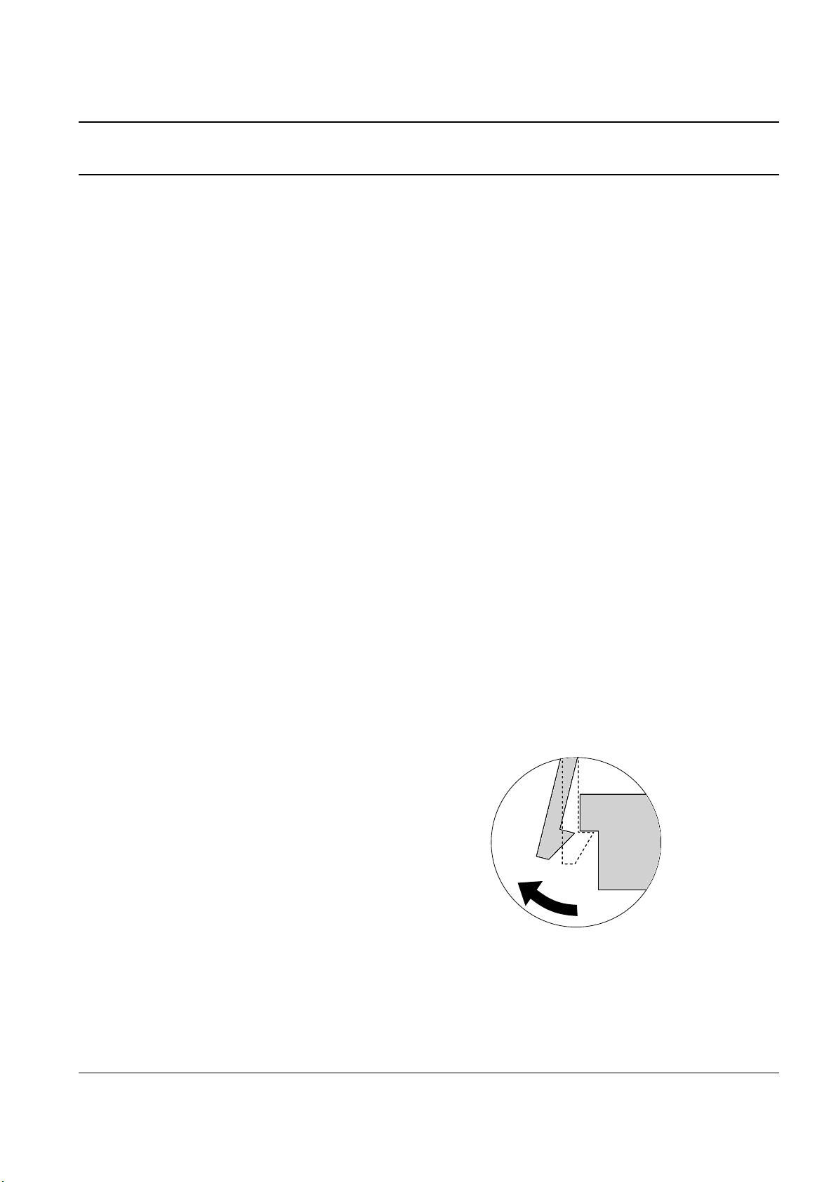
Releasing Plastic Latches
Many of the parts are held in place with plastic
latches. The latches break easily; release them carefully. To remove such parts, press the hook end of
the latch away from the part to which it is latched.
Disassembly and Reassembly
3-2 Samsung Electronics
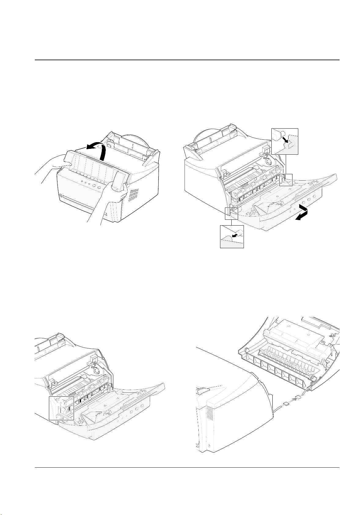
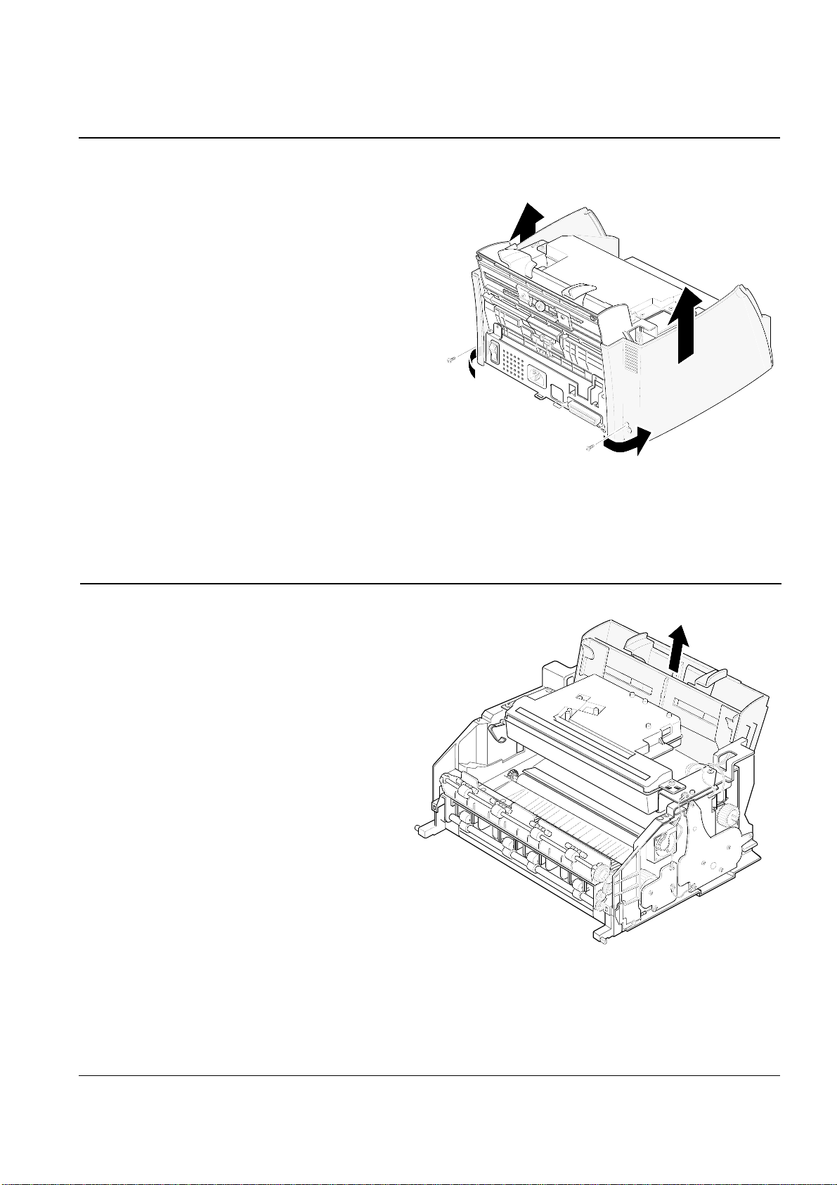
3-2 OPE Cover
1. Hold both sides of the cover and pull it towards
you.
3. Release the right-bottom of the cover, then pull it
in the direction of arrow to release the other end.
2. Remove the one screw to release the stopper
securing the cover to the main body.
4. Unplug the connector connecting the OPE cover
to the main body and remove the cover.
Disassembly and Reassembly
3-3Samsung Electronics
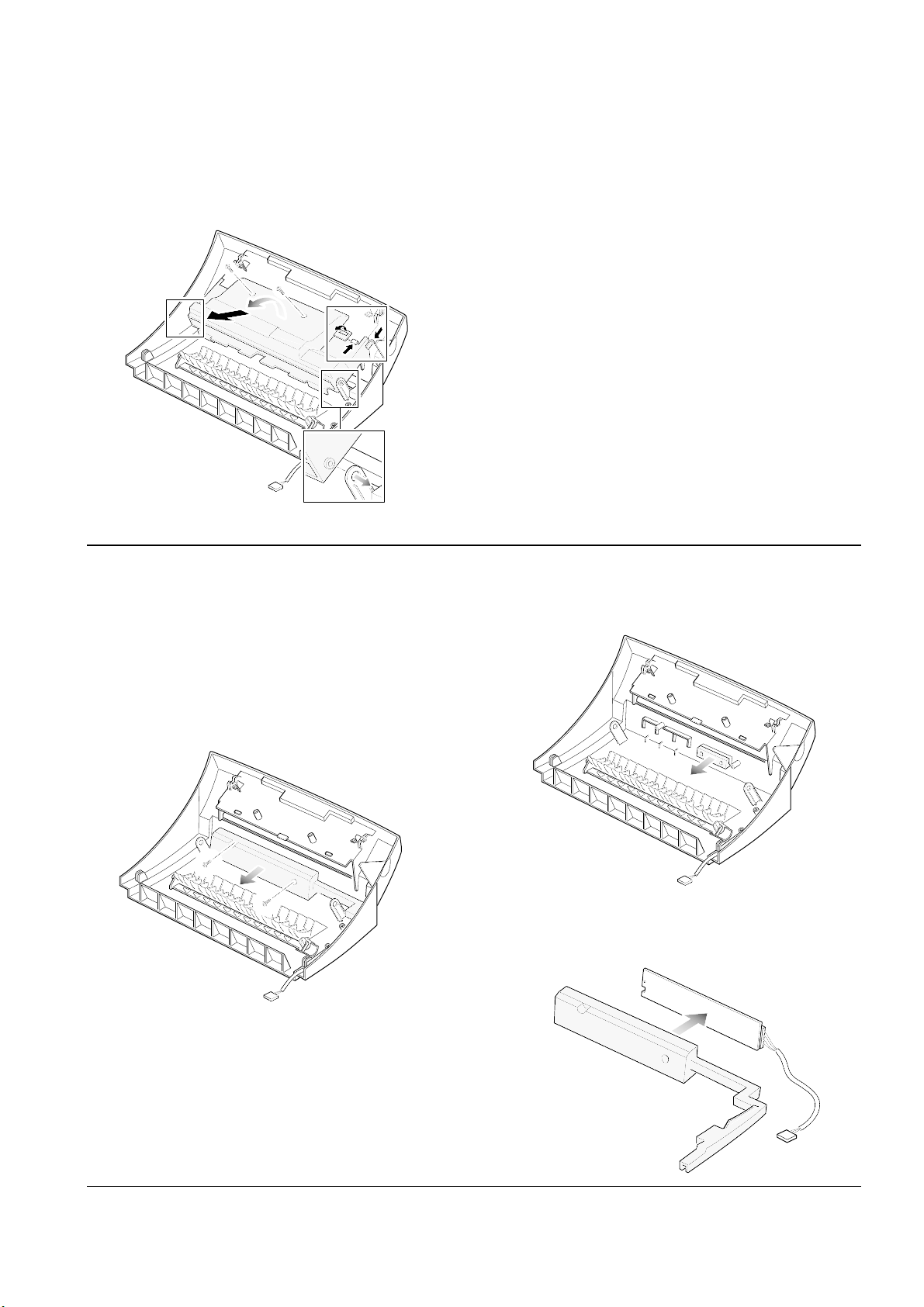
5. Remove the two screws and pull the guide stacker in the direction of arrow. Then Spread out the
parts securing the guide stacker on both sides to
release the cover.
3. Remove the LED.
4. Remove the PCB from the cover PCB.
3-3 OPE Board
1. Before you remove the board, you should
remove the OPE cover (see page 3-2).
2. Remove the three screws, then remove the cover
PCB.
Disassembly and Reassembly
3-4 Samsung Electronics
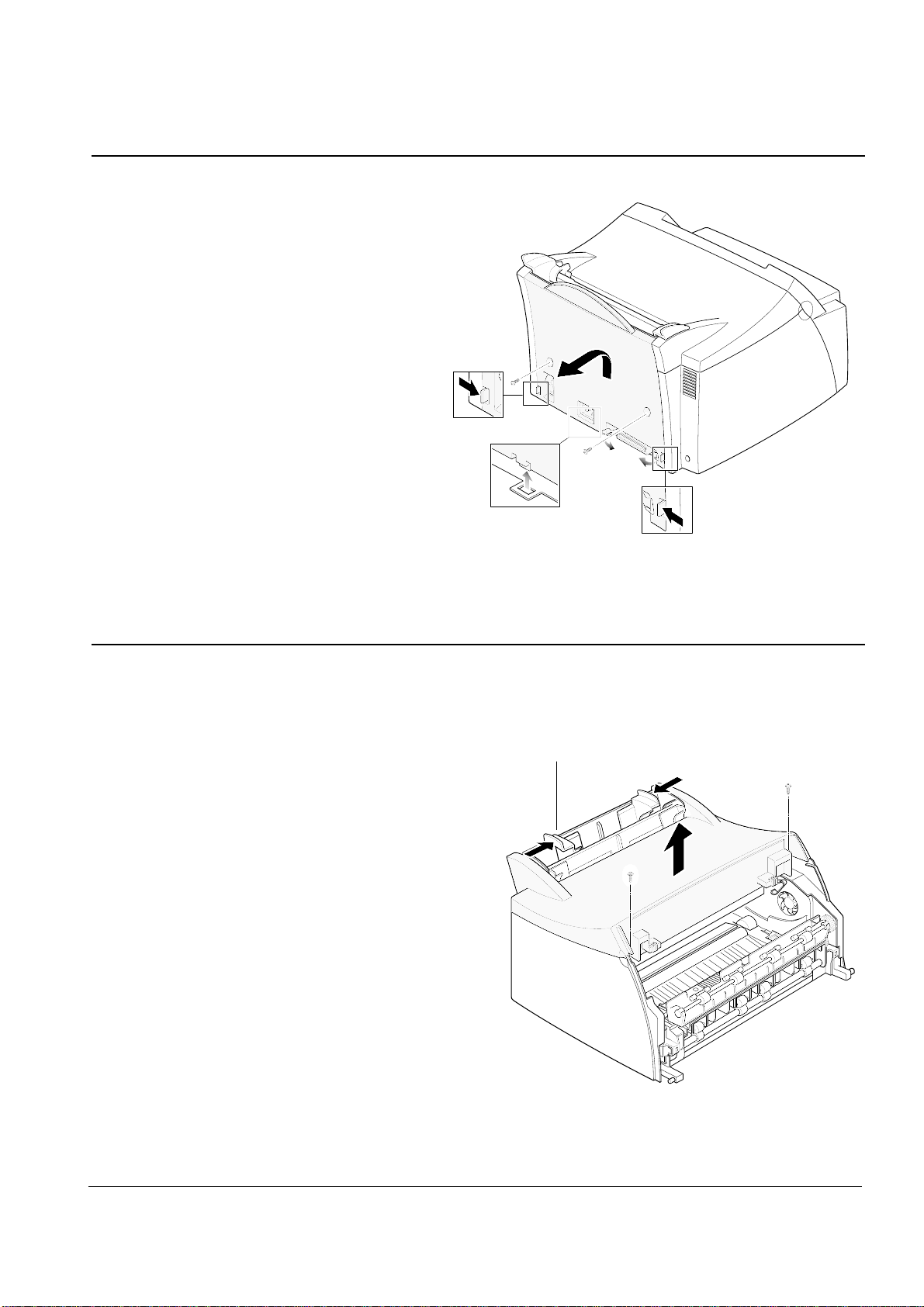
3-4 Rear Cover
1. Remove the two screws on the back of the
machine.
2. Pull the handles on both sides in the direction of
the arrows then lift the rear cover to unlatch it
from the bottom, then remove the cover.
3-5 Top Cover
1. Before you remove the top cover, you should
remove:
– OPE cover (see page 3-2)
– Rear cover (see above)
2. Slide the paper guide on the paper tray inwards.
Remove the two screws on the top cover, then
remove the cover.
Paper guides
Disassembly and Reassembly
3-5Samsung Electronics
3-7 Paper Tray
1. Before you remove the paper tray, you should
remove:
– OPE cover (see page 3-2)
– Rear cover (see page 3-4)
– Top cover (see page 3-4)
– Side covers (see above)
2. Take out the tray from the main frame.
3-6 Side covers (R, L)
1. Before you remove the top cover, you
should remove:
– OPE cover (see page 3-2)
– Rear cover (see page 3-4)
– Top cover (see page 3-4).
2. Remove the two screws and pull the left and right side
covers in the direction of arrow.
Disassembly and Reassembly
3-6 Samsung Electronics
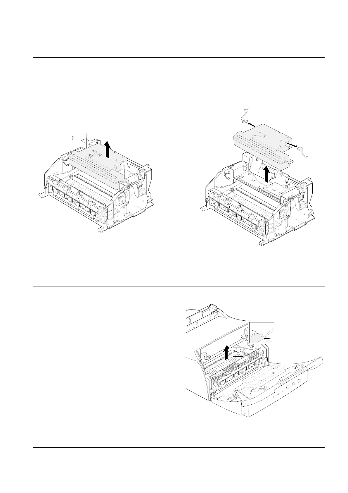
3-8 LSU
1. Before you remove the LSU, you should remove:
– All covers (see page 3-2, 3-4, 3-5)
2. Remove the three screws securing the LSU.
3-9 Transfer Roller
1. Open the front cover.
2. Lift the transfer roller using a proper tool as
shown in the figure and take out the roller.
3. Unplug two connectors from the LSU and
remove the LSU.
Disassembly and Reassembly
3-7Samsung Electronics
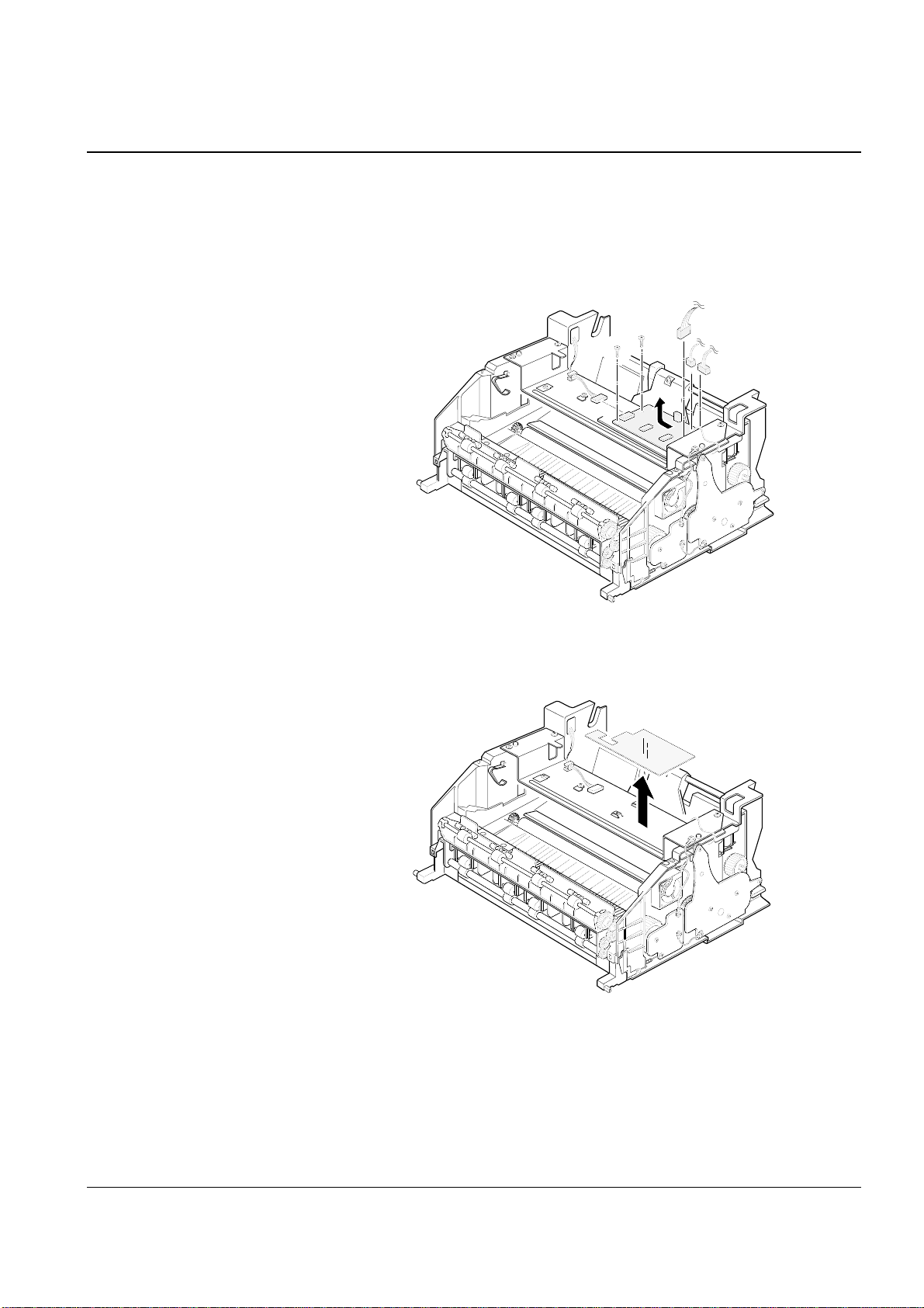
3-10 Engine Board
1. Before you remove the engine board, you should
remove:
– All covers (see page 3-2, 3-4, 3-5)
– LSU (see page 3-6)
2. Unplug the four connectors and remove the two
screws from the engine board, then pull the
board in the direction of arrow.
3. Remove the Insulator which was under the
engine board.
 Loading...