


SERVICE
LASER PRINTER
ML-4500/XEV
SAMSUNG
Manual
LASER PRINTER CONTENTS
1. Precautions
2. Specifications
3. Disassembly and Reassembly
4. Troubleshooting
5. Exploded Views and Parts List
6. Electrical Parts List
7. Block Diagrams
8. Connection Diagrams
9. PCB Diagrams
10.Schematic Dagrams

ELECTRONICS
© Samsung Electronics Co.,Ltd. February 2001
Printed in Korea.
VERSION NO. : 1.00 P/N.: JC-0046A

1. Precautions
Follow these safety, ESD, and servicing precautions to prevent personal injury and equipment damage.
1-1 Safety Precautions
1. Be sure that all built-in protective devices are in
place. Restore any missing protective shields.
2. Make sure there are no cabinet openings through
which people- particularly children- might insert
fingers or objects and contact dangerous voltages.
3. When re-installing chassis and assemblies, be
sure to restore all protective devices, including
control knobs and compartment covers.
4. Design Alteration Warning:
Never alter or add to the mechanical or electrical
design of this equipment, such as auxiliary
connectors, etc. Such alterations and
modifications will void the manufacturer’s
warranty.
5. Components, parts, and wiring that appear to
have overheated or are otherwise damaged
should be replaced with parts which meet the
original specifications. Always determine the
cause of damage or overheating, and correct any
potential hazards.
6. Observe the original lead dress, especially near
sharp edges, AC, and high voltage power
supplies. Always inspect for pinched, out-ofplace, or frayed wiring. Do not change the
spacing between components and the printed
circuit board.
7. Product Safety Notice:
Some electrical and mechanical parts have special
safety-related characteristics which might not be
obvious from visual inspection. These safety
features and the protection they provide could be
lost if a replacement component differs from the
original. This holds true, even though the
replacement may be rated for higher voltage,
wattage, etc.
Components critical for safety are indicated in
the parts list with symbols . Use only
replacement components that have the same
ratings, especially for flame resistance and
dielectric specifications. A replacement part that
does not have the same safety characteristics as
the original may create shock, fire, or other safety
hazards.
Samsung Electronics 1-1

1-2 Samsung Electronics
Precautions
1-2 ESD Precautions
Certain semiconductor devices can be easily
damaged by static electricity. Such components are
commonly called “Electrostatically Sensitive (ES)
Devices”, or ESDs. Examples of typical ESDs are:
integrated circuits, some field effect transistors, and
semiconductor “chip” components.
The techniques outlined below should be followed
to help reduce the incidence of component damage
caused by static electricity.
CAUTION: Be sure no power is applied to the
chassis or circuit, and observe all other safety
precautions.
1. Immediately before handling a semiconductor
component or semiconductor-equipped assembly,
drain off any electrostatic charge on your body
by touching a known earth ground. Alternatively,
employ a commercially available wrist strap
device, which should be removed for your personal
safety reasons prior to applying power to the unit
under test.
2. After removing an electrical assembly equipped
with ESDs, place the assembly on a conductive
surface, such as aluminum or copper foil, or
conductive foam, to prevent electrostatic charge
buildup in the vicinity of the assembly.
3. Use only a grounded tip soldering iron to solder
or desolder ESDs.
4. Use only an “anti-static” solder removal device.
Some solder removal devices not classified as
“anti-static” can generate electrical charges
sufficient to damage ESDs.
5. Do not use Freon-propelled chemicals. When
sprayed, these can generate electrical charges
sufficient to damage ESDs.
6. Do not remove a replacement ESD from its
protective packaging until immediately before
installing it. Most replacement ESDs are
packaged with all leads shorted together by
conductive foam, aluminum foil, or a comparable
conductive material.
7. Immediately before removing the protective
shorting material from the leads of a replacement
ESD, touch the protective material to the chassis
or circuit assembly into which the device will be
installed.
8. Maintain continuous electrical contact between
the ESD and the assembly into which it will be
installed, until completely plugged or soldered
into the circuit.
9. Minimize bodily motions when handling
unpackaged replacement ESDs. Normal motions,
such as the brushing together of clothing fabric
and lifting one’s foot from a carpeted floor, can
generate static electricity sufficient to damage an
ESD.
1. Exercise caution when replacing a super
capacitor or Lithium battery. There could be a
danger of explosion and subsequent operator
injury and/or equipment damage if incorrectly
installed.
2. Be sure to replace the battery with the same or
equivalent type recommended by the
manufacturer.
3. Super capacitor or Lithium batteries contain toxic
substances and should not be opened, crushed,
or burned for disposal.
1-3 Super Capacitor or Lithium Battery Precautions

2. Specification
2-1 Printer
Print Speed 8 PPM (Letter Size, 5% Charcter Pattern) At Copy Mode
Resolution 600 X 600 DPI
Source of Light Laser Diode(LSU)
Print Method Non-impact Electrophotography, Laser Beam
Feed Method Multi-Purpose Feeder and Manual
Feed Reference Center Reference Loading
Paper Size Bin Type
Normal Paper : A4,Letter,Legal,B5,
Executive, A5
Envelope : Normal Envelope
Length : 149 ~ 365mm
Width : 100 ~ 216mm
Weight : For MPF, 60 ~ 90g/m
2
For Manual, 60 ~163g/m
2
Paper Capacity MPF : 150 Sheets (based on 75g/m2)
Manual Slot : 1 Sheet
Paper Stacker Capacity Face up : 100 Sheets (75g/m2,20 lb)
Warming up Time 30 Sec
First Printing Time Stand-By : 20Sec
Power Save Mode :Less than 5min
Power Rating AC 110V ~120V ± 15% 50/60Hz ± 3Hz,
AC 220V ~ 240V ± 15% 50/60Hz ± 3Hz
Power Consumption Avg. 180Wh
Power Saving Consumption Avg. 10Wh Sleep Mode
Certification & Compliance FCC, C-UL, CE, CB,TUV
Acoustic Noise Stand-by : Less than 35dB
Sleep Mode : Less than 29dB
Operating : Less than 50dB
Samsung Electronics 2-1

2-2 Samsung Electronics
Toner Cartridge One-Cartridge type
Expected Life Span 50,000 Sheets
Operating Environment Temperature : 10 ~ 32°C
Humidity : 20 ~ 85%
Storage Environment Temperature : -20 ~ 40°C
Humidity : 10 ~ 95%RH
Weight Net : Max.6.5kg(with Accessory)
Gross : Max. 9kg
External Dimension 329(W) X 343(D) x 224(H)mm
Developer . Life Span : 5% Pattern,Min. 2,500/1,000 Sheets
. Developing : Non-magnetic
Contact Developing
. Charging : Conductive Roller Charging
. Density Adjustment : Normal/Economic Mode selectable by the
PC driver (Only ML-4500)
. Toner Supply Method : Exchanging
Toner Cartridge
. New Developer Checkable
. Transfer System : Conductive Roller Transfer
. Fusing System : Temperature & Pressure
. OZONE Emission : Max. 0.1 PPM(8 Hours)
Specification

Samsung Electronics 2-3
Specification
2-2 Quality
Conditions
Paper Normal Paper 75g/m
2
Environment Temperature : 20 ~ 25°C
Humidity : 40 ~ 60%
Print Quality
Image Density Min. 1.3
Min. 1.0(Temperature : 10 ~ 15°C)
Background Max. 0.2
Uniformity Max. 0.2(Including Continuous Print)
Fusing Min. 80% (All Black) 75g/m
2
Start Position Top : x ± 4.23mm, Side : y ± 4mm From Left
Skew Top : Max. ± 1.5mm/117.9mm
Side : Max. ±1.8mm/241.3mm
Orthogonality ± 1.0mm
Horizontal Scan ± 0.6mm/208mm
(Bowed Line Skew : Pattern 1)
Special Paper Exception Image Density : Min 1.0 (Envelope)
Fusing : Min. 70% (All Black)
(Envelope/OHP/Postcard)
Paper Jam Less than 1/1,000(75g/m2Paper)
Paper Curl First : Less than 10mm (10 Sheets, 75g/m2Paper)
After Cooling : Less than 10mm (10 Sheets, 75g/m2Paper)
Reliability
Insulation Resistance Less than 10 MΩ (at DC 500V)
Dielectric Strength AC 1000V (DC 1420V), 10mA
Ground Continuity Less than 0.1Ω
Voltage DIP Rated Voltage ± 15%
AC Impulse Noise AC 1000V 10, 100, 200, 400, 1000ns Rated Power
Leakage Current Less than 3.5mA
Surge 6 KV, 500A/3 KV, 500A
OZONE Emission Less than 0.1 ppm (8 Hours)
Top Cover Open Isolating the input power of the LSU,
High Voltage Part, and Fuser
Overcurrent Protect Fuse inside the SMPS
Fusing System
Trouble Sensing .The temperature doesn’t rise to the specific
temperature in the specific time.
.The temperature is too high.
Overheat Sensing 240 ~ 250°C (The thermostat cuts off the Fuser
from the power.)
Thermistor Open Sensing : Without the initial
temperature change of the Fuser
Indicate the
Fuser error

2-4 Samsung Electronics
Specification
2-3 SMPS (Switching Mode Power Supply)
Input (AC)
AC Input Voltage Europe USA
Minimum 198V 90V
Typical 230V 120V
Maximum 264V 135V
Max. AC Input Current 2.5Amps 3Amps
Max. Inrush Current Ap-p (at 20°C)
Output (DC)
Line Regulation 24V ± 10%
5V ± 5%
Road Regulation 24V ± 10%
5V ± 5%,-5V ± 5%
Ripple Noise 24V : Peak 300mV
-5V : Peak 500mV
5V : Peak 500mV
Over Current Protect 24V : 2.7A ± 10% (by Circuit)
5V : A ± 10% (by Circuit)
Over Voltage Protect 24V : 33VDC
5V : 5.6VDC

3-1Samsung Electronics
3. Disassembly and Reassembly
3-1 General Precautions on Disassembly
When you disassemble and reassemble components, you must use extreme caution. The close proximity of
cables to moving parts makes proper routing a must. If components are removed, any cables disturbed by the
procedure must be restored as close as possible to their original positions. Before removing any component
from the machine, note the cable routing that will be affected.
Whenever servicing the machine, you must perform as follows:
1. Remove the print cartridge. Do not expose the cartridge to direct room light or sun light, and be careful not
to scratch the drum surface.
2. Turn the power switch off.
3. Unplug all the cables from the printer.
4. Replace with only an authorized component.
5. Do not force to open or fasten a plastic material component.
6. Be careful no obstacles are included when you reassemble components.
7. When you reassemble components, be careful small size components are located in place.
8. If you turn the machine over to replace some parts, toner or paper particles may contaminate the LSU window. Protect the LSU window with clean paper.
Releasing Plastic Latches
Many of the parts are held in place with plastic
latches. The latches break easily; release them carefully. To remove such parts, press the hook end of
the latch away from the part to which it is latched.
Disassembly and Reassembly
3-2 Samsung Electronics
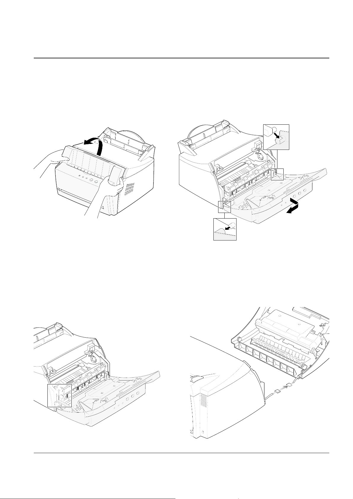
3-2 OPE Cover
1. Hold both sides of the cover and pull it towards
you.
3. Release the right-bottom of the cover, then pull it
in the direction of arrow to release the other end.
2. Remove the one screw to release the stopper
securing the cover to the main body.
4. Unplug the connector connecting the OPE cover
to the main body and remove the cover.
Disassembly and Reassembly
3-3Samsung Electronics
5. Remove the two screws and pull the guide stacker in the direction of arrow. Then Spread out the
parts securing the guide stacker on both sides to
release the cover.
3. Remove the LED.
4. Remove the PCB from the cover PCB.
3-3 OPE Board
1. Before you remove the board, you should
remove the OPE cover (see page 3-2).
2. Remove the three screws, then remove the cover
PCB.
Disassembly and Reassembly
3-4 Samsung Electronics
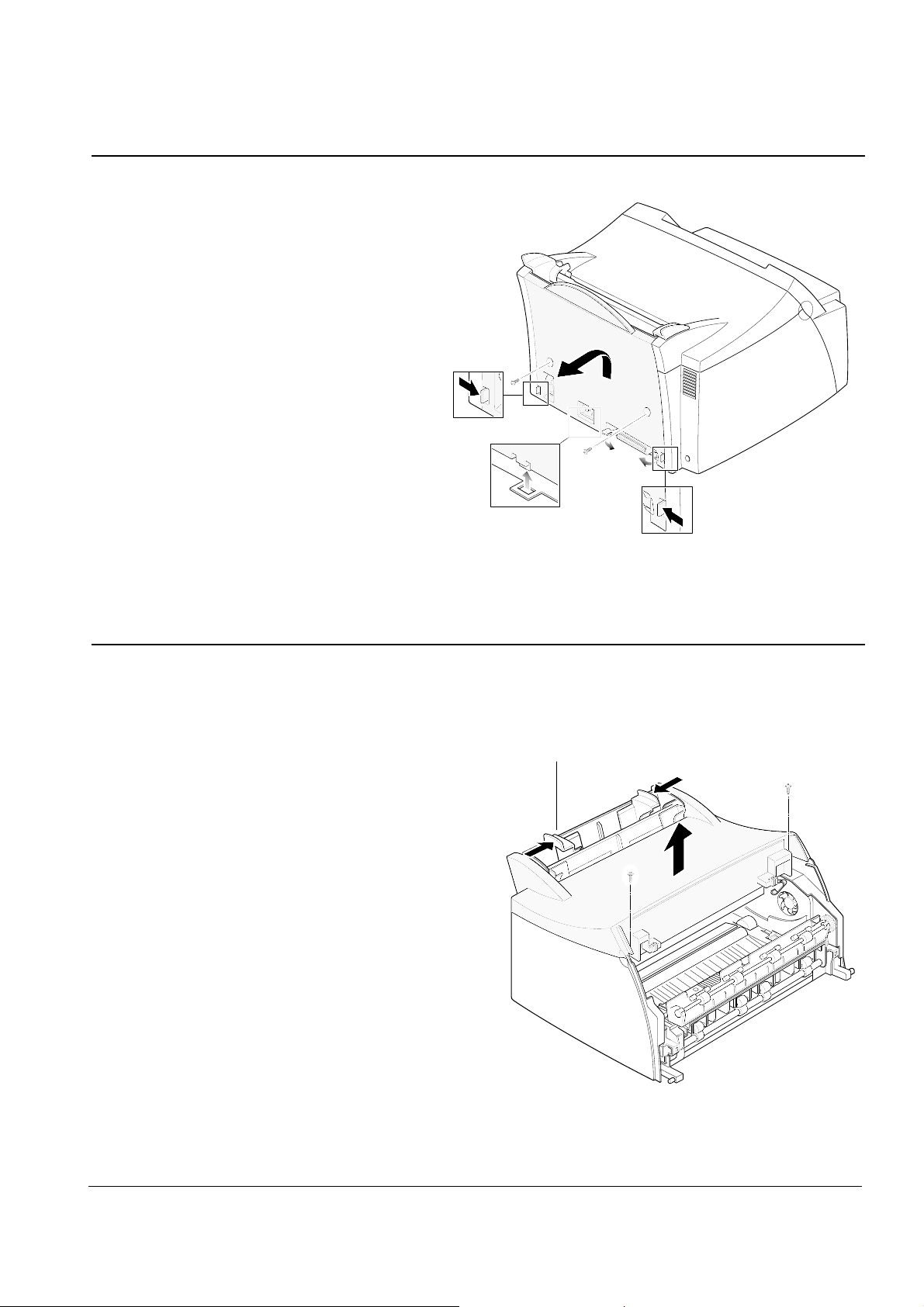
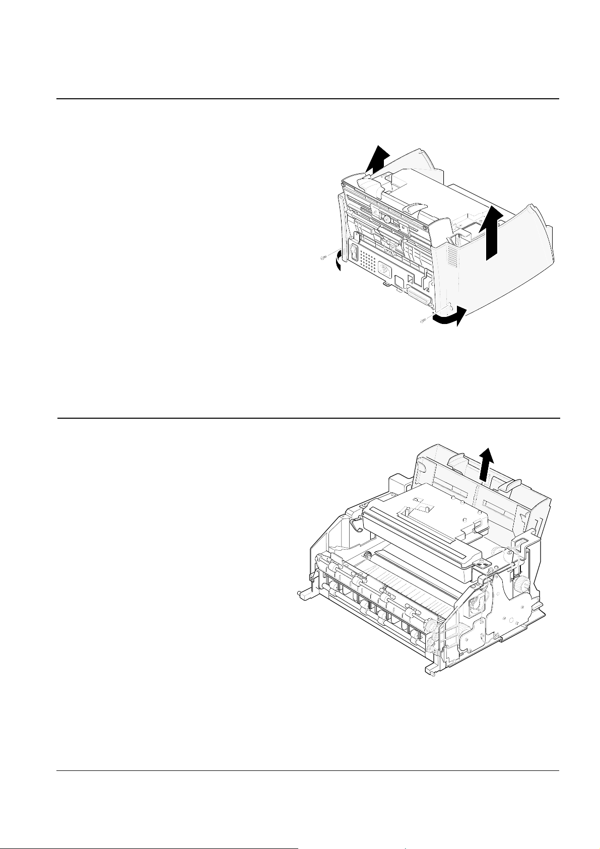
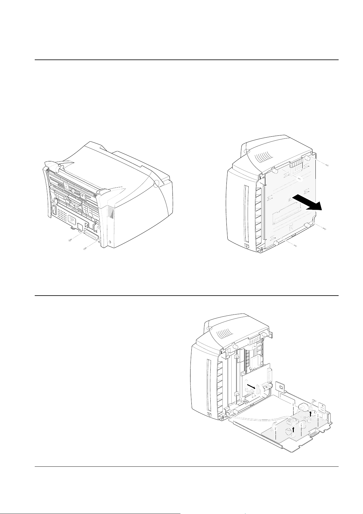
3-4 Rear Cover
1. Remove the two screws on the back of the
machine.
2. Pull the handles on both sides in the direction of
the arrows then lift the rear cover to unlatch it
from the bottom, then remove the cover.
3-5 Top Cover
1. Before you remove the top cover, you should
remove:
– OPE cover (see page 3-2)
– Rear cover (see above)
2. Slide the paper guide on the paper tray inwards.
Remove the two screws on the top cover, then
remove the cover.
Paper guides
Disassembly and Reassembly
3-5Samsung Electronics
3-7 Paper Tray
1. Before you remove the paper tray, you should
remove:
– OPE cover (see page 3-2)
– Rear cover (see page 3-4)
– Top cover (see page 3-4)
– Side covers (see above)
2. Take out the tray from the main frame.
3-6 Side covers (R, L)
1. Before you remove the top cover, you
should remove:
– OPE cover (see page 3-2)
– Rear cover (see page 3-4)
– Top cover (see page 3-4).
2. Remove the two screws and pull the left and right side
covers in the direction of arrow.
Disassembly and Reassembly
3-6 Samsung Electronics
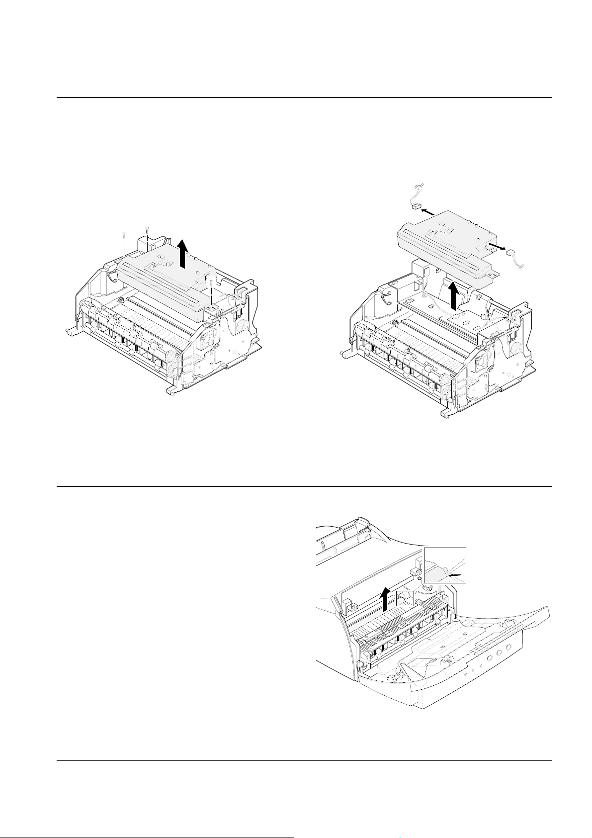
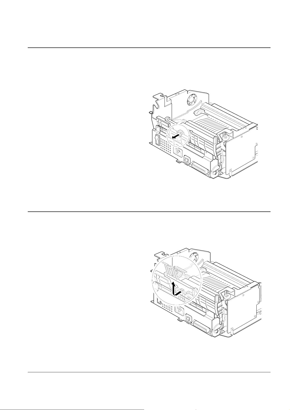
3-8 LSU
1. Before you remove the LSU, you should remove:
– All covers (see page 3-2, 3-4, 3-5)
2. Remove the three screws securing the LSU.
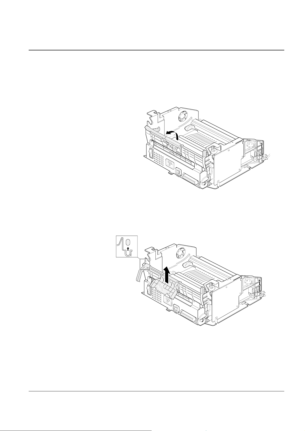
3-9 Transfer Roller
1. Open the front cover.
2. Lift the transfer roller using a proper tool as
shown in the figure and take out the roller.
3. Unplug two connectors from the LSU and
remove the LSU.
Disassembly and Reassembly
3-7Samsung Electronics
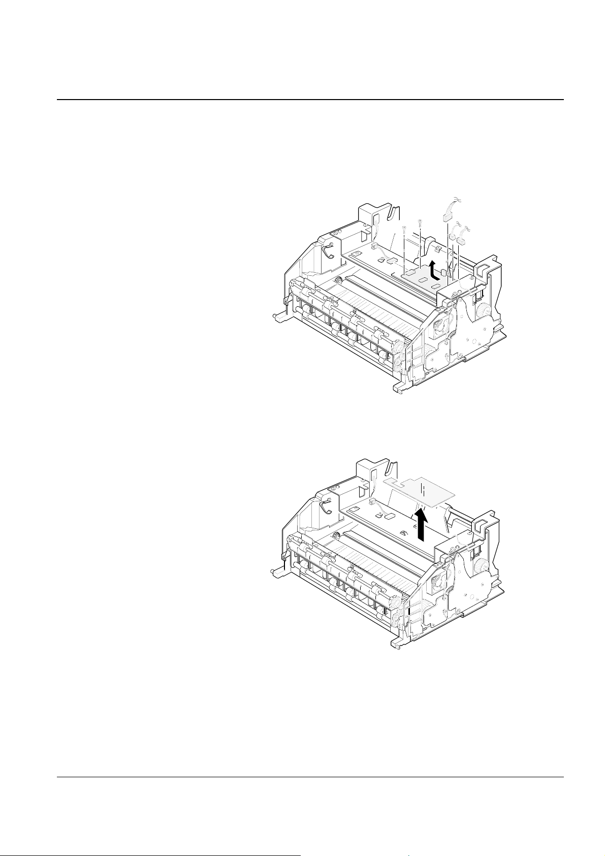
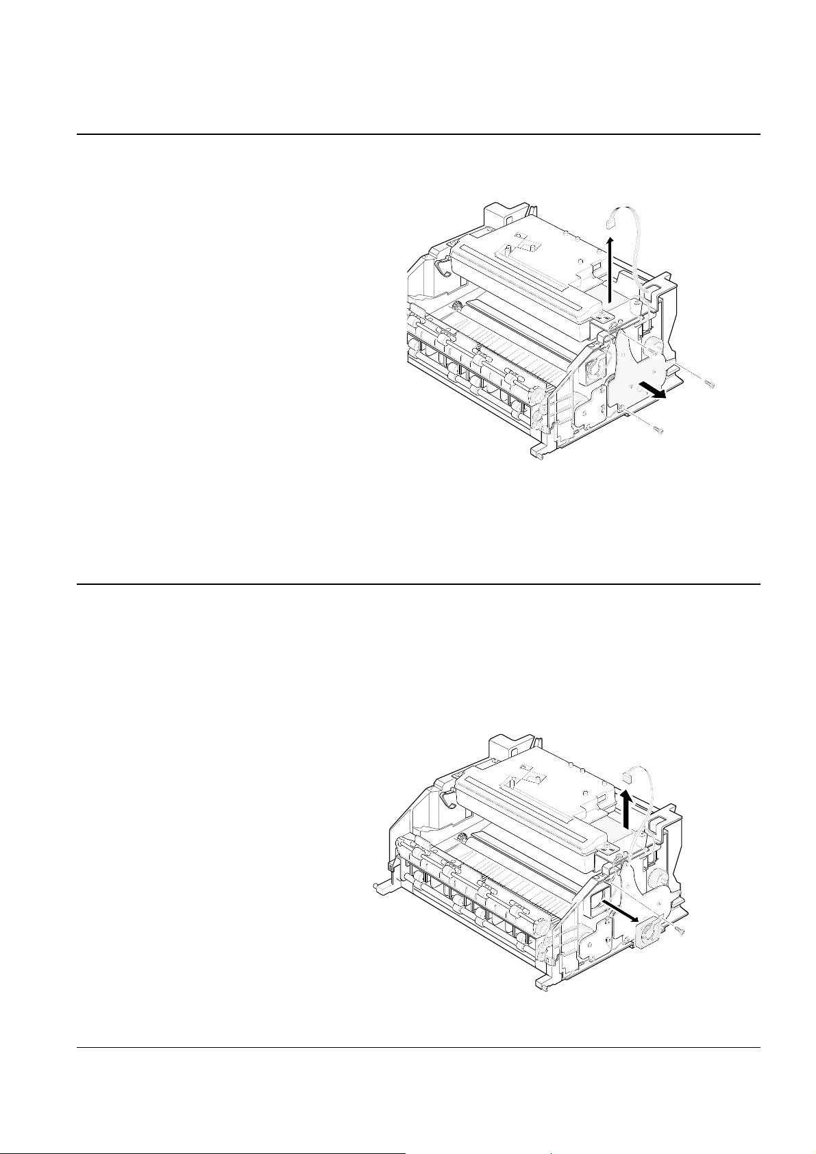
3-10 Engine Board
1. Before you remove the engine board, you should
remove:
– All covers (see page 3-2, 3-4, 3-5)
– LSU (see page 3-6)
2. Unplug the four connectors and remove the two
screws from the engine board, then pull the
board in the direction of arrow.
3. Remove the Insulator which was under the
engine board.
Disassembly and Reassembly
3-8 Samsung Electronics
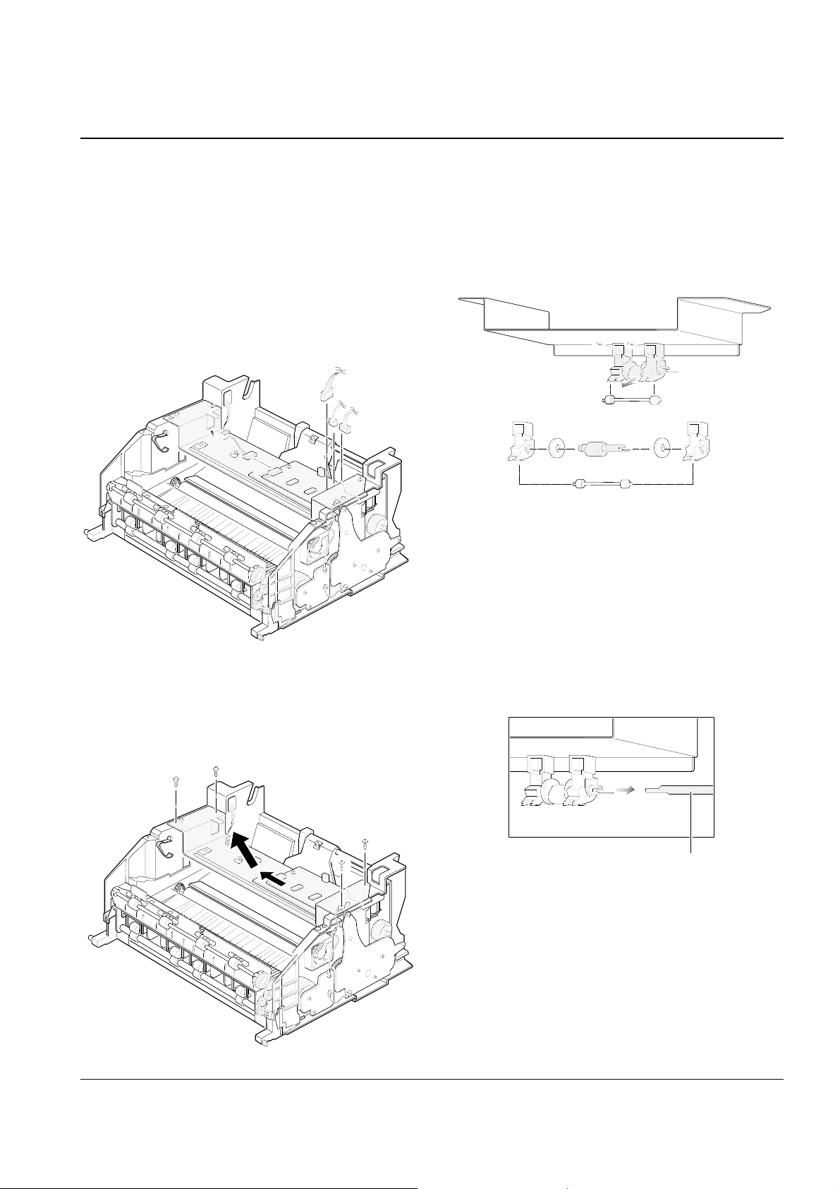
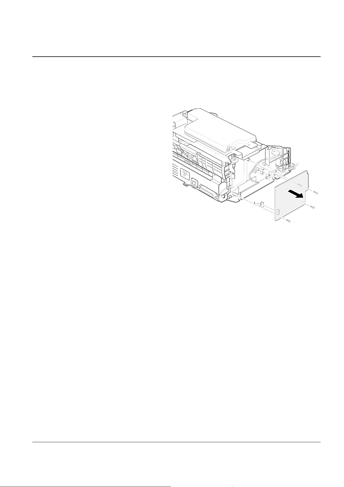
3-11 Pick-up Roller ass’y
1. Before you remove the pick-up roller ass’y,
you should remove:
– All covers (see page 3-2, 3-4, 3-5)
– LSU (see page 3-6)
2. Unplug all the connectors from the engine board.
3. Remove the four screws securing the plate and
remove the plate as shown below.
4. Remove the two screws and remove the roller
from the plate.
Note: When you reassemble the pick-up roller,
make sure that the right end of the pick-up
roller fits into the pick-up gear shaft.
Pick-up gear
shaft
Disassembly and Reassembly
3-9Samsung Electronics
3-12 Knock-up ass’y
1. Before you remove the knock-up ass’y, you should
remove:
– All covers (see page 3-2, 3-4, 3-5)
– LSU (see page 3-6)
– Plate in the pick-up roller ass’y (see page 3-8)
2. Pull the knock-up ass’y fully backward.
3. Remove the knock-up ass’y from the main frame.
Make sure it is properly unlatched.
Disassembly and Reassembly
3-10 Samsung Electronics
3-13 Cap-pad
1. Before you remove the cap-pad, you should
remove:
– All covers (see page 3-2, 3-4, 3-5)
– LSU (see page 3-6)
– Plate in the pick-up roller ass’y (see page 3-8)
– Knock-up ass’y (see page 3-10)
2. Take out the cap-pad from the main frame.
3-14 Holder-pad
1. Before you remove the holder-pad, you should
remove:
– All covers (see page 3-2, 3-4, 3-5)
– LSU (see page 3-6)
– Plate in the pick-up roller ass’y (see page 3-8)
– Knock-up ass’y (see page 3-10)
2. Remove the holder-pad from the main frame.
Disassembly and Reassembly
3-11Samsung Electronics
3-15 Motor ass’y
1. Before you remove the motor ass’y, you should
remove:
– All covers (see page 3-2, 3-4, 3-5)
2. Remove the three screws securing the motor
ass’y and unplug one connector from the engine
board, then remove the motor ass’y.
3-16 Fan
1. Before you remove the fan, you should remove:
– All covers (see page 3-2, 3-4, 3-5)
2. Unplug the one connector on the fan from the
engine board, remove the one screw, then
remove the fan.

Disassembly and Reassembly
3-12 Samsung Electronics
3-17 Gear Pick-up ass’y
1. Before you remove the gear pick-up ass’y, you
should remove:
– All covers (see page 3-2, 3-4, 3-5)
Note: When you reassemble the gear, make sure
that the direction of the gear is correct.
2. Spread out the two snap-fits on the gear to
release the gear, then remove the gear pick-up
ass’y from the main frame.
3-18 Solenoid
1. Before you remove the solenoid, you should
remove:
– All covers (see page 3-2, 3-4, 3-5)
2. Unplug the connector on the solenoid from the
engine board, remove the one screw, then
remove the solenoid.
Disassembly and Reassembly
3-13Samsung Electronics
3-19 HVPS Board
1. Before you remove the HVPS board, you should
remove:
– All covers (see page 3-2, 3-4, 3-5)
2. Remove three three screws and the connector
from the HVPS board, then remove the board.
Note: when you reassemble the board, make sure
that the five terminals are correctly inserted in
place.
Disassembly and Reassembly
3-14 Samsung Electronics
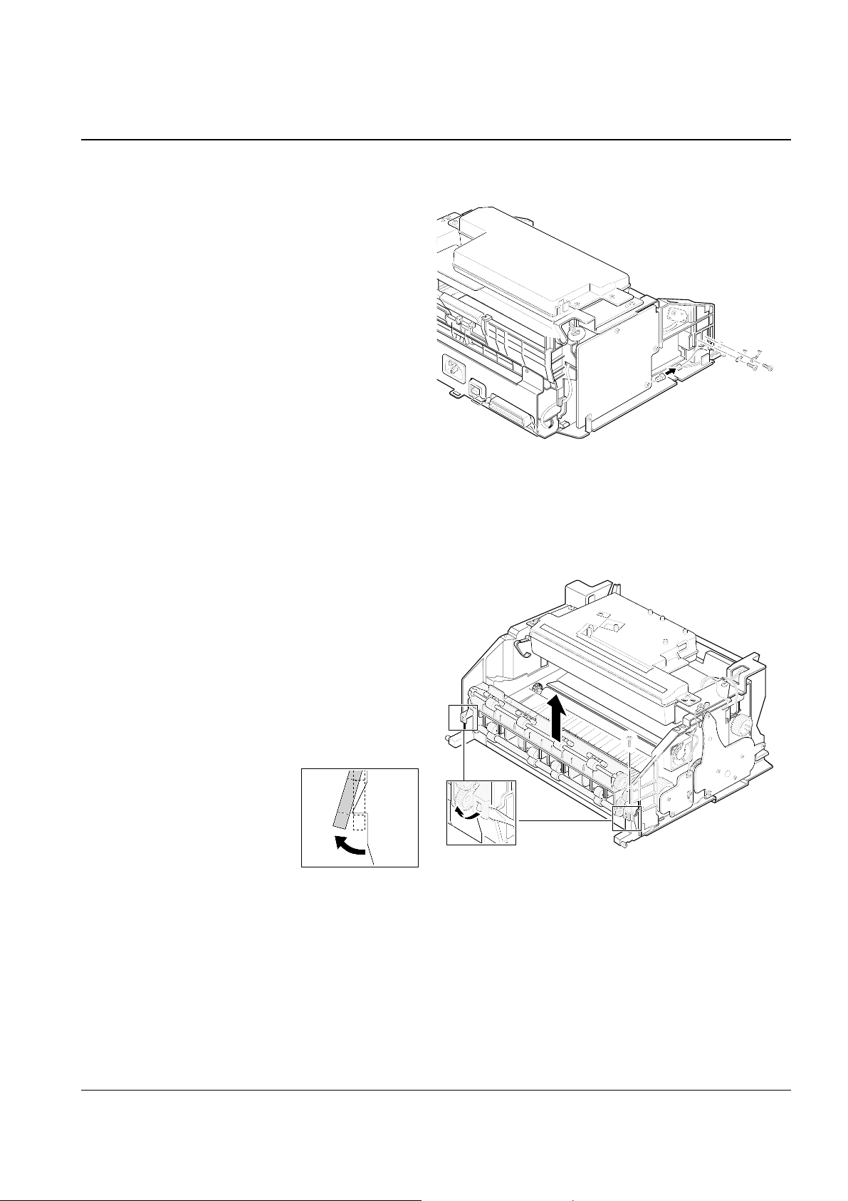
3-20 Fuser ass’y
1. Before you remove the fuser ass’y, you should
remove:
– All covers (see page 3-2, 3-4, 3-5)
2. Remove the two ground screws and unplug the
one connector as shown in the figure.
3. Remove the one screw and unlatch the fuser
ass’y using a proper tool as shown in the figure,
then remove the fuser ass’y.
Disassembly and Reassembly
3-15Samsung Electronics
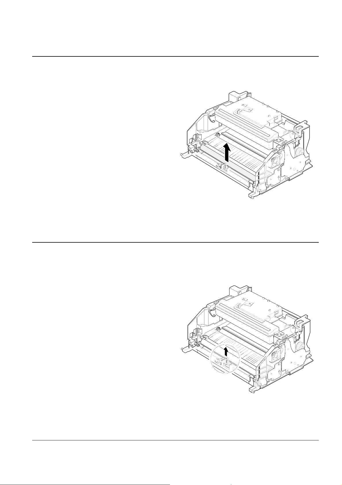
3-21 Pressure Roller
1. Before you remove the pressure roller, you
should remove:
– All covers (see page 3-2, 3-4, 3-5)
– Fuser ass’y (see page 3-15)
2. Lift and remove the pressure roller from the
main frame.
3-22 Actuator-exit
1. Before you remove the actuator-exit, you should
remove:
– All covers (see page 3-2, 3-4, 3-5)
– Fuser ass’y (see page 3-15)
2. Lift and remove the actuator-exit from the main
frame.
Disassembly and Reassembly
3-16 Samsung Electronics
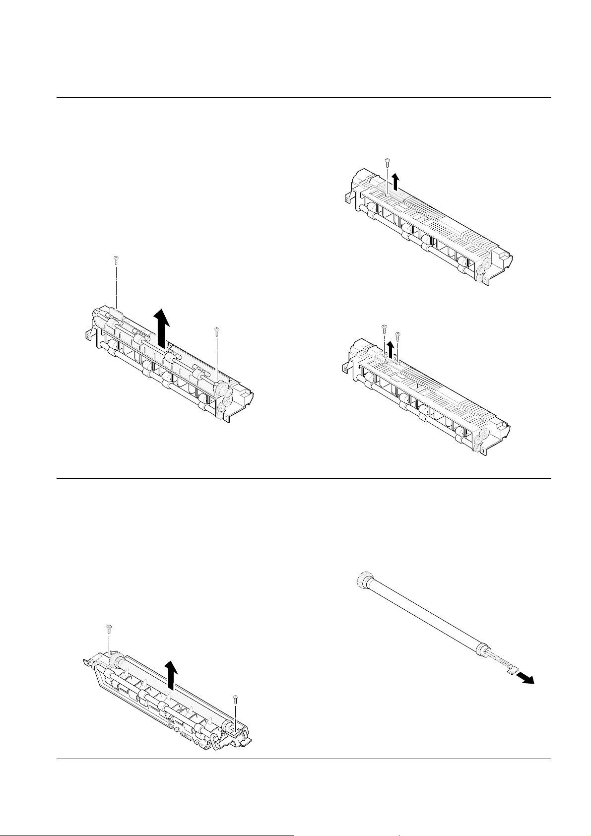
3-23 Thermostat
1. Before you remove the thermostat, you should
remove:
– All covers (see page 3-2, 3-4, 3-5)
– Fuser ass’y (see page 3-15)
2. Remove the two screw securing the face up and
remove the face up.
4. Remove the two screws and take out thermostat
from the fuser ass’y.
3. Remove the halogen lamp from the heat roller.
3-24 Halogen Lamp
1. Before you remove the thermostat, you should
remove:
– All covers (see page 3-2, 3-4, 3-5)
– Fuser ass’y (see page 3-15)
2. On the fuser ass’y, remove the two screws, then
remove the heat roller.
3. On the fuser ass’y, remove the one screw, then
remove the thermostat cover.
Disassembly and Reassembly
3-17Samsung Electronics
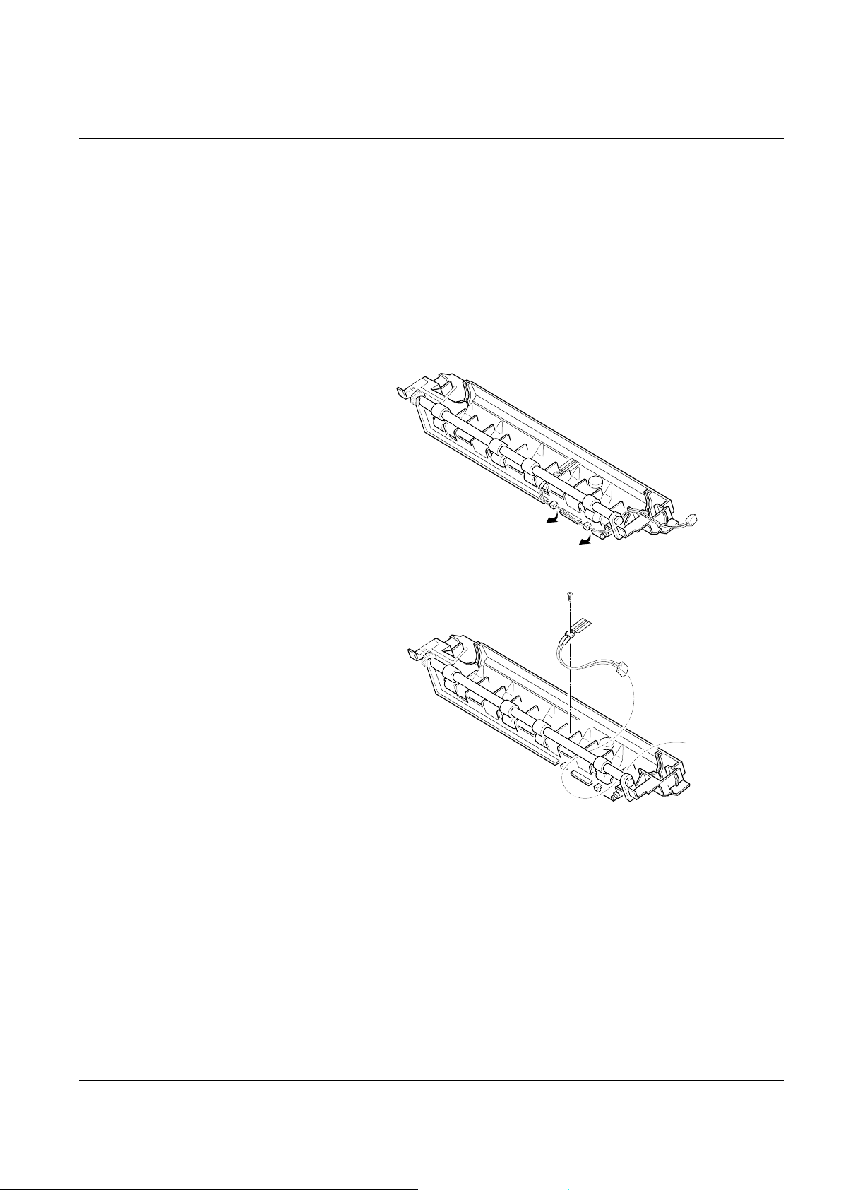
3-25 Thermistor
1. Before you remove the thermister, you should remove:
– All covers (see page 3-2, 3-4, 3-5)
– Fuser ass’y (see page 3-15)
2. On the fuser ass’y, remove the heat roller as described
on page 3-17.
3. Unwrap the thermister wire as shown in the figure.
4. Remove the one screw, then remove the thermister.
Disassembly and Reassembly
3-18 Samsung Electronics
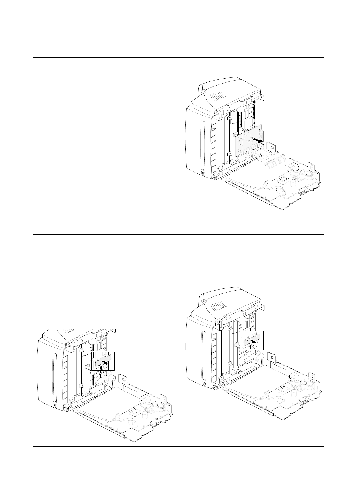
3-26 Shield Engine ass’y
1. Before you remove the shield engine ass’y, you
should remove:
– Rear cover (see page 3-4)
2. Remove the two screws.
3. Remove the four screws securing the shield
engine ass’y and remove the shield engine ass’y
from the main frame.
3-27 SMPS Board
1. Before you remove the SMPS board, you should
remove:
– Rear cover (see page 3-4)
– Shield engine ass’y (see above)
2. Remove the four screws and on the SMPS board,
unplug the two connectors from the SMPS board
and the one connector from the main board, then
remove the SMPS board.
Disassembly and Reassembly
3-19Samsung Electronics
3-28 Main Board
1. Before you remove the main board, you should
remove:
– Rear cover (see page 3-4)
– Shield engine ass’y (see page 3-19)
2. Remove the two screws unplug and all the connectors from the main board, then remove the
board.
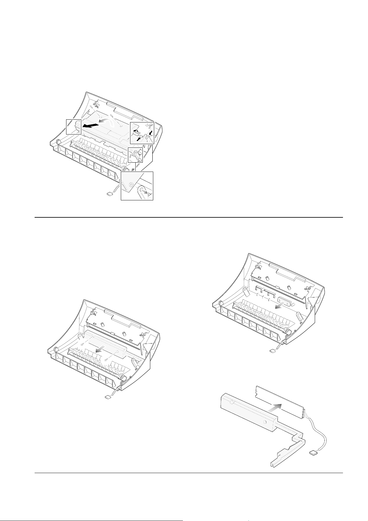
3-29 Sensor Board
1. Before you remove the sensor board, you should
remove:
– Rear cover (see page 3-4)
– Shield engine ass’y (see page 3-19)
2. Release four snap-fits securing the insulator
engine board and remove the insulator engine
board.
3. Release four snap-fits securing the sensor board,
then remove the sensor board.
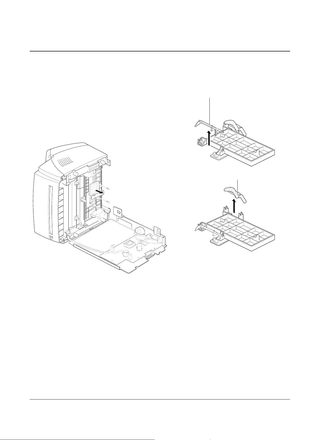
Disassembly and Reassembly
3-20 Samsung Electronics
Feed sensor
Empty sensor
3-30 Feed Sensor and Empty Sensor
1. Before you remove these parts, you should
remove:
– Rear cover (see page 3-4)
– Shield engine ass’y (see page 3-19)
2. Unplug the one connector from the main board
and remove the two screws securing the holder
feed ass’y, then remove the holder feeder ass’y.
3. Remove the feed sensor and the empty sensor.
Disassembly and Reassembly
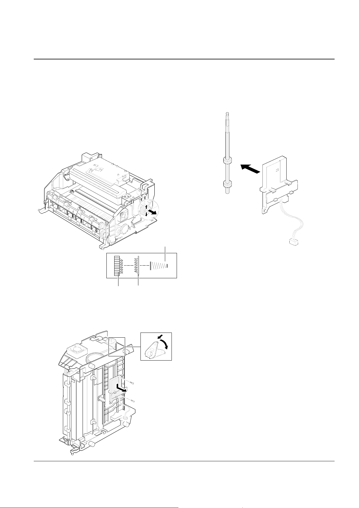
3-21Samsung Electronics
Gear-feed
Clutch-feed
Spring-clutch
3-31 Feed Roller
1. Before you remove the roller, you should
remove:
– All covers (see page 3-2, 3-4, 3-5)
– Motor ass’y (see page 3-12)
2. Spread out the two snap-fits on the gear to
release the gear, then remove gear-feed, springclutch and clutch-feed from the gear.
3. Remove the feed roller from the holder.
3. Rotate the pick-up bushing in the direction of
arrow, then remove the the feed roller ass’y.

Disassembly and Reassembly
3-22 Samsung Electronics
MEMO