

Samsung ltm295 service manual
LCD-TV
Chassis Model
AL29NO LTM295W
AL40NO LTM405W
Manual
SERVICE
LCD-TV CONTENTS
1. Precautions
2. Product Specifications
3. Disassembly & Reassembly
4. Alignment & Adjustments
5. Troubleshooting
6. Exploded View & Parts List
7. Electrical Parts List
8. Block Diagram
9. Wiring Diagram
10. Schematic Diagrams
11. Panel Description
CONFIDENTIAL
1-1-1 Warnings
1. For continued safety, do not attempt to modify the
circuit board.
2. Disconnect the AC power and DC Power Jack
before servicing.
1-1-2 Servicing the LCD Monitor
1. When servicing the LCD Monitor disconnect the
AC line cord from the AC outlet.
2. It is essential that service technicians have an
accurate voltage meter available at all times. Check
the calibration of this meter periodically.
1-1-3 Fire and Shock Hazard
Before returning the monitor to the user, perform the
following safety checks:
1. Inspect each lead dress to make certain that the
leads are not pinched or that hardware is not
lodged between the chassis and other metal parts in
the monitor.
2. Inspect all protective devices such as nonmetallic
control knobs, insulating materials, cabinet backs,
adjustment and compartment covers or shields,
isolation resistor-capacitor networks, mechanical
insulators, etc.
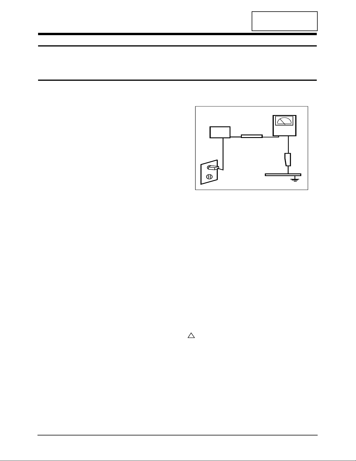
3. Leakage Current Hot Check (Figure 1-1):
WARNING:
Do not use an isolation transformer during this test.
Use a leakage current tester or a metering system
that complies with American National Standards
Institute (ANSI C101.1, Leakage Current for
Appliances), and Underwriters Laboratories (UL
Publication UL1410, 59.7).
Figure 1-1. Leakage Current Test Circuit
4. With the unit completely reassembled, plug the AC
line cord directly into a 120V AC outlet. With the
unit’s AC switch first in the ON position and then
OFF, measure the current between a known earth
ground (metal water pipe, conduit, etc.) and all
exposed metal parts, including: metal cabinets,
screwheads and control shafts. The current
measured should not exceed 0.5 milliamp. Reverse
the power-plug prongs in the AC outlet and repeat
the test.
1-1-4 Product Safety Notices
Some electrical and mechanical parts have special
safety-related characteristics which are often not
evident from visual inspection. The protection they give
may not be obtained by replacing them with
components rated for higher voltage, wattage, etc. Parts
that have special safety characteristics are identified by
on schematics and parts lists. A substitute
replacement that does not have the same safety
characteristics as the recommended replacement part
might create shock, fire and / or other hazards. Product
safety is under review continuously and new
instructions are issued whenever appropriate.
LTM295W/LTM405W 1-1
CONFIDENTIAL
1 Precautions
Follow these safety, servicing and ESD precautions to prevent damage and to protect against potential hazards such as
electrical shock.
1-1 Safety Precautions
DEVICE
UNDER
TEST
TEST ALL
EXPOSED METAL
SURFACES
(READING SHOULD
NOT BE ABOVE 0.5mA)
LEAKAGE
CURRENT
TESTER
2-WIRE CORD
ALSO TEST WITH
PLUG REVERSED
(USING AC ADAPTER
PLUG AS REQUIRED)
EARTH
GROUND
!

1-2-1 General Servicing Precautions
1. Always unplug the unit’s AC power cord from the
AC power source and disconnect the DC Power
Jack before attempting to:
(a) remove or reinstall any component or assembly,
(b) disconnect PCB plugs or connectors, (c) connect
a test component in parallel with an electrolytic
capacitor.
2. Some components are raised above the printed
circuit board for safety. An insulation tube or tape
is sometimes used. The internal wiring is
sometimes clamped to prevent contact with
thermally hot components. Reinstall all such
elements to their original position.
3. After servicing, always check that the screws,
components and wiring have been correctly
reinstalled. Make sure that the area around the
serviced part has not been damaged.
1. Immediately before handling any semiconductor
components or assemblies, drain the electrostatic
charge from your body by touching a known earth
ground. Alternatively, wear a discharging wriststrap device. To avoid a shock hazard, be sure to
remove the wrist strap before applying power to
the monitor.
2. After removing an ESD-equipped assembly, place it
on a conductive surface such as aluminum foil to
prevent accumulation of an electrostatic charge.
3. Do not use freon-propelled chemicals. These can
generate electrical charges sufficient to damage
ESDs.
4. Use only a grounded-tip soldering iron to solder or
desolder ESDs.
5. Use only an anti-static solder removal device. Some
solder removal devices not classified as “anti-static”
can generate electrical charges sufficient to damage
ESDs.
4. Check the insulation between the blades of the AC
plug and accessible conductive parts (examples:
metal panels, input terminals and earphone jacks).
5. Insulation Checking Procedure: Disconnect the
power cord from the AC source and turn the power
switch ON. Connect an insulation resistance meter
(500 V) to the blades of the AC plug.
The insulation resistance between each blade of the
AC plug and accessible conductive parts (see
above) should be greater than 1 megohm.
6. Always connect a test instrument’s ground lead to
the instrument chassis ground before connecting
the positive lead; always remove the instrument’s
ground lead last.
6. Do not remove a replacement ESD from its
protective package until you are ready to install it.
Most replacement ESDs are packaged with leads
that are electrically shorted together by conductive
foam, aluminum foil or other conductive materials.
7. Immediately before removing the protective
material from the leads of a replacement ESD,
touch the protective material to the chassis or
circuit assembly into which the device will be
installed.
Caution: Be sure no power is applied to the
chassis or circuit and observe all
other safety precautions.
8. Minimize body motions when handling
unpackaged replacement ESDs. Motions such as
brushing clothes together, or lifting your foot from
a carpeted floor can generate enough static
electricity to damage an ESD.
1 Precautions
1-2 LTM295W/LTM405W
CONFIDENTIAL
1-3 Electrostatically Sensitive Devices (ESD) Precautions
Some semiconductor (solid state) devices can be easily damaged by static electricity. Such components are commonly
called Electrostatically Sensitive Devices (ESD). Examples of typical ESD are integrated circuits and some field-effect
transistors. The following techniques will reduce the incidence of component damage caused by static electricity.
1-2 Servicing Precautions
WARNING: An electrolytic capacitor installed with the wrong polarity might explode.
Caution: Before servicing units covered by this service manual, read and follow the Safety Precautions
section of this manual.
Note: If unforeseen circumstances create conflict between the following servicing precautions and any of the
safety precautions, always follow the safety precautions.
CONFIDENTIAL
2 Product Specifications
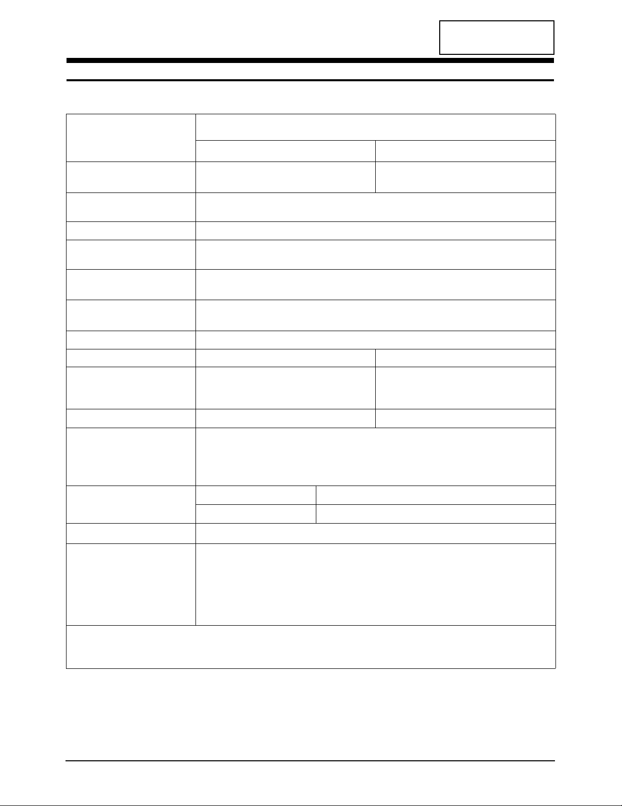
2-1 Specifications
LCD Panel
TFT-LCD panel, RGB vertical stripe, normally black TFT-LCD panel, RGB vertical stripe, normally black
transmissive, (29 -Inch) viewable, 0.4935 mm pixel pitch
transmissive, (40-Inch) viewable, 0.6735 mm pixel pitch
Scanning Frequency Horizontal : 30 KHz ~ 60 KHz
Vertical : 56 Hz ~ 75 Hz
Display Colors 16,777,216 Million colors
Maximum Resolution Horizontal : 1280 Pixels
Vertical : 768 Pixels
Input Video Signal Analog, 0.7 Vp-p ± 5% positive at 75 Ω,
internally terminated
Input Sync Signal Type : Seperate H/V sync, Composite H/V, Sync-on-Green
Level : TTL level
AC power voltage & Frequency AC 90 ~ 240V 60 Hz/50 Hz ± 3 Hz, DC 28V / 8A
Power Consumption 160W (max) 220W (max)
Dimensions
Unit (W x D x H)
29.9 x 7.7 x 22.4 Inches (759.6 x 195.0 x 568.5 mm)
39.6 x 11.8 x 29.4 Inches (1006.0 x 300.0 x 746.5 mm)
Carton (W x D x H)
37.8 x 7.7 x 22.4 Inches (961.2 x 195.0 x 568.5 mm)
49.1 x 11.8 x 29.4 Inches (1247.6 x 300.0 x 746.5 mm)
Weight (Net / Gross)
Environmental Considerations Operating Temperature : 50°F ~ 104°F (10°C ~ 40°C)
Humidity : 10 % ~ 80 %
Storage Temperature : -4°F ~ 113°F (-20°C ~ 45°C)
Humidity : 5 % ~ 95 %
TV System
Sound Characteristics •Max Internal speaker Out : Right c 10 W / Leftc 10 W
•Bass control Range : -6 ± -12dB ~ +6 ± 12dB
•TREBLE control Range : -10 ± -12dB ~ +10 ± 12dB
•Output frequency : RFc 80 Hz~15 KHz /A/Vc 80 Hz~20 KHz
•Line out : RFc 80 Hz~15 KHz /A/Vc 80 Hz~20 KHz
•SyncMaster LTM295W/LTM405W comply with SWEDAC (MPRII) recommendations for reduced electromagnetic fields.
•Designs and specifications are subject to change without prior notice.
LTM295W/LTM405W 2-1
Item
Description
LTM295W
LTM405W
18.0 kg (39.682 lbs) 28.0 kg ( 61.715 lbs)
Antena Input 75Ω, Coaxial Cable
Color NTSC-M
Sound BTSC, A2 STEREO, EIAJ

CONFIDENTIAL
2-2 Pin Assignments
Pin No.
30 Pin Signal Cable (DVI Analog)
Pin No.
30 Pin Signal Cable (DVI Analog)
1
2
3
4
5
6
7
8
9
10
11
12
13
14
15
16
17
18
19
20
21
22
23
24
25
26
27
28
29
30
RX2+
RX2GND
RX1+
RX1GND
RX0+
RX0GND
RXC+
RXCGND
DDC (Clock)
DDC (Data)
GND
GND
Check • D-Sub
GND
DDC_5V
DDC_5V
GND
V/Sync
GND
H/Sync
GND
Blue
GND
Green
GND
Red
CONFIDENTIAL
2 Product Specifications
LTM295W/LTM405W 2-3
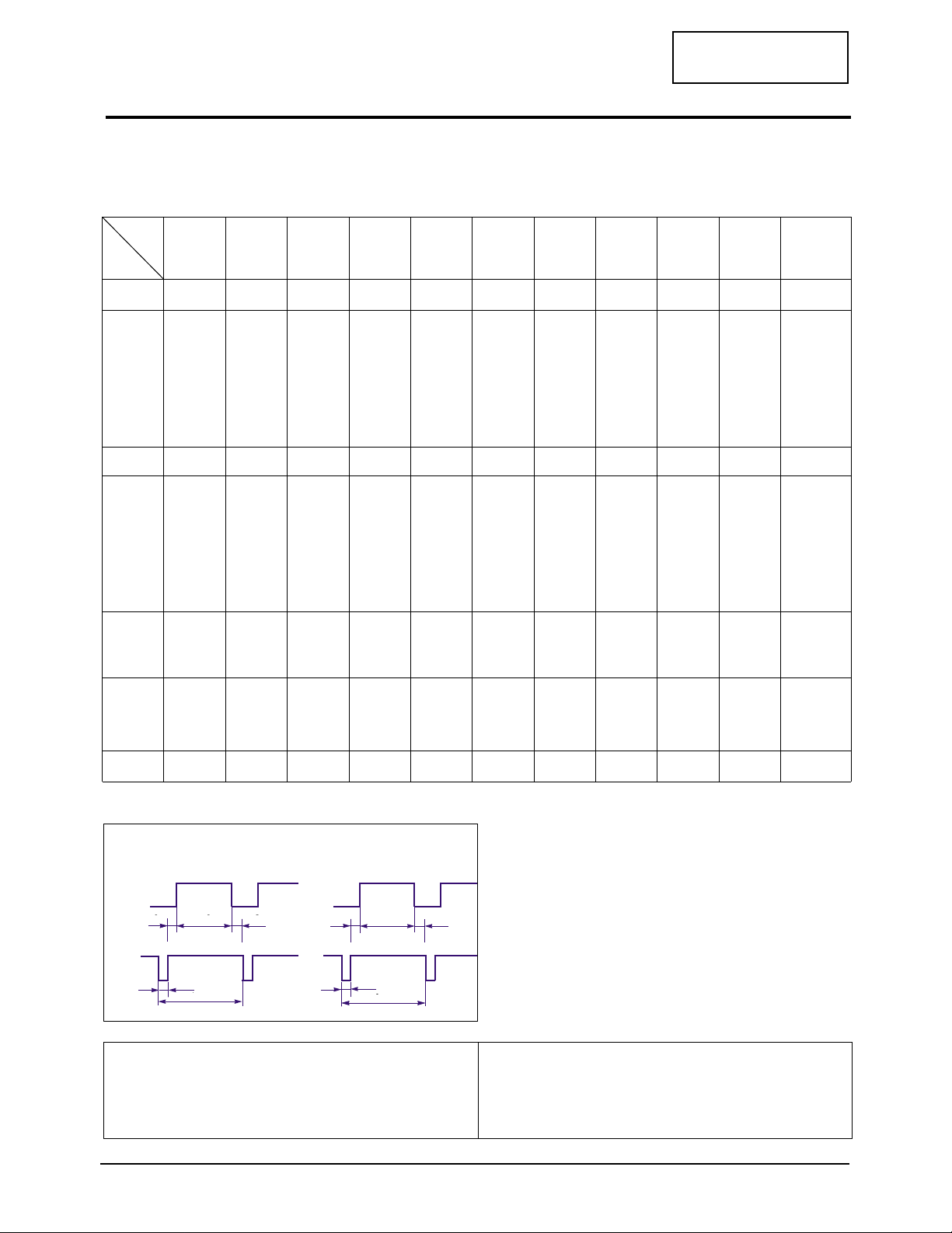
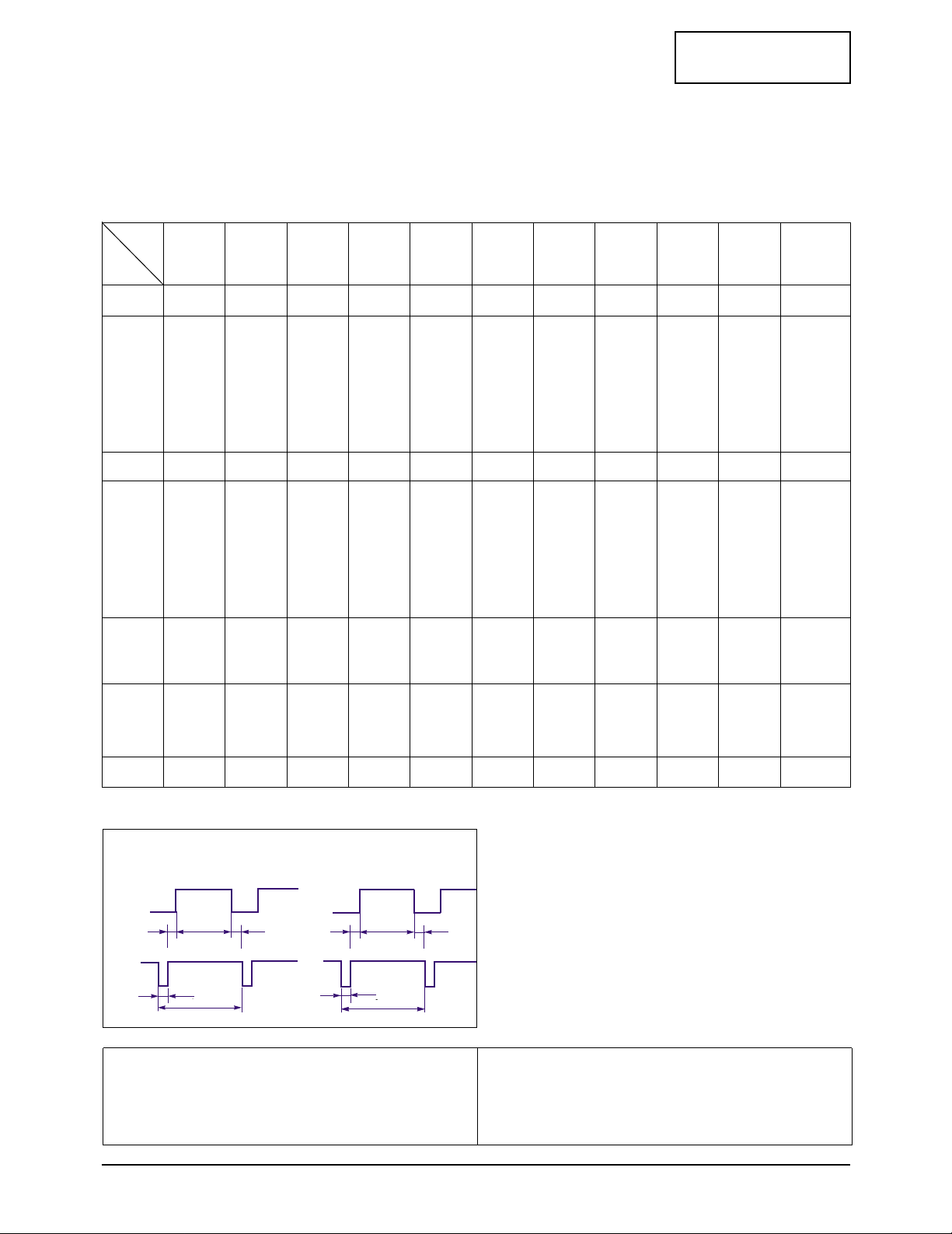
2-3 Timing Chart
This section of the service manual describes the timing that the computer industry recognizes as standard
for computer-generated video signals.
48.1
1040
120
64
800
56
72.2
666
6
23
600
37
50.000
Positive
Positive
Separate
37.9
1056
128
88
800
40
60.3
628
4
23
600
1
40.000
Positive
Positive
Separate
35.2
1024
72
128
800
24
56.3
625
2
22
600
1
36.000
–/+
–/+
Separate
SVGA/56 Hz
800 x 600
SVGA/60 Hz
800 x 600
SVGA/72 Hz
800 x 600
MAC/66 Hz
640 x 480
35.0
864
64
96
640
64
66.7
525
3
39
480
3
30.240
Negative
Negative
Separate
44.955
1650
40
70
1280
260
59.94
750
5
20
720
5
74.176
–/+
–/+
Separate
fH (kHz)
A µsec
B µsec
C µsec
D µsec
E µsec
fV (Hz)
O msec
P msec
Q msec
R msec
S msec
Clock
Freq.
(MHz)
Polarity
H.Sync
V.Sync
Remark
VGA3/60 Hz
640 x 480
VGA/72 Hz
640 x 480
VGA/75 Hz
640 x 480
VGA/85 Hz
640 x 480
MAC/60 Hz
640 x 480
DTV/
59.94 Hz
1280 x 720
DTV/
59.94 Hz
1920 x 1080
Table 2-1 Timing Chart
33.716
2200
44
44
1920
192
59.94
1125
15
2
1080
5
74.176
–/+
–/+
Separate
31.5
800
96
40
640
8
60.0
525
2
25
480
2
25.175
Negative
Negative
Separate
37.9
832
40
120
640
16
72.8
520
3
20
480
1
31.500
Negative
Negative
Separate
37.5
840
64
120
640
16
75.0
500
3
16
480
1
31.500
Negative
Negative
Separate
43.3
832
56
80
640
56
85.0
509
3
25
480
1
36.000
Negative
Negative
Separate
31.5
800
96
48
640
16
60.0
525
2
33
480
10
25.175
Negative
Negative
Separate
Mode
Timing
QRS
P
O
Video
Sync
Sync
Horizontal
Vertical
CDE
P
O
B
A
Video
Sync
Sync
Separate Sync
C D
A
O
E
B
P
Video
Sync
Sync
Video
Q R S
A : Line time total B : Horizontal sync width O : Frame time total P : Vertical sync width
C : Back porch D : Active time Q : Back porch R : Active time
E : Front porch S : Front porch
CONFIDENTIAL
2 Product Specifications
2-4 LTM295W/LTM405W
68.7
1456
128
144
1152
32
75.1
915
3
39
870
3
100.000
Negative
Negative
Separate
67.5
1600
128
256
1152
64
75.0
900
3
32
864
1
108.000
Positive
Positive
Separate
60.2
1328
96
176
1024
32
74.9
804
3
30
768
3
80.000
Negative
Negative
Separate
MAC/74 Hz
1024 x 768
VESA/75 Hz
1152 x 864
MAC/75 Hz
1152 x 870
MAC/60 Hz
1024 x 768
48.8
1312
96
128
1024
64
60.0
813
6
33
768
6
64.000
Negative
Negative
Separate
46.9
1056
80
160
800
16
75.0
625
3
21
600
1
49.500
Positive
Positive
Separate
fH (kHz)
A µsec
B µsec
C µsec
D µsec
E µsec
fV (Hz)
O msec
P msec
Q msec
R msec
S msec
Clock
Freq.
(MHz)
Polarity
H.Sync
V.Sync
Remark
MAC/74 Hz
832 x 624
XGA/60 Hz
1024 x 768
XGA/70 Hz
1024 x 768
XGA/75 Hz
1024 x 768
XGA/85 Hz
1024 x 768
SVGA/75 Hz
800 x 600
SVGA/85 Hz
800 x 600
Table 2-2 Timing Chart (continued)
53.7
1048
64
152
800
32
85.1
631
3
27
600
1
56.250
Positive
Positive
Separate
49.7
1152
64
224
832
32
74.6
667
3
39
624
1
57.284
Negative
Negative
Separate
48.4
1344
136
160
1024
24
60.0
806
6
29
768
3
65.000
Negative
Negative
Separate
56.5
1328
136
144
1024
24
70.1
806
6
29
768
3
75.000
Negative
Negative
Separate
60.0
1312
96
176
1024
16
75.0
800
3
28
768
1
78.750
Positive
Positive
Separate
68.7
1376
96
208
1024
48
85.0
808
3
36
768
1
94.500
Positive
Positive
Separate
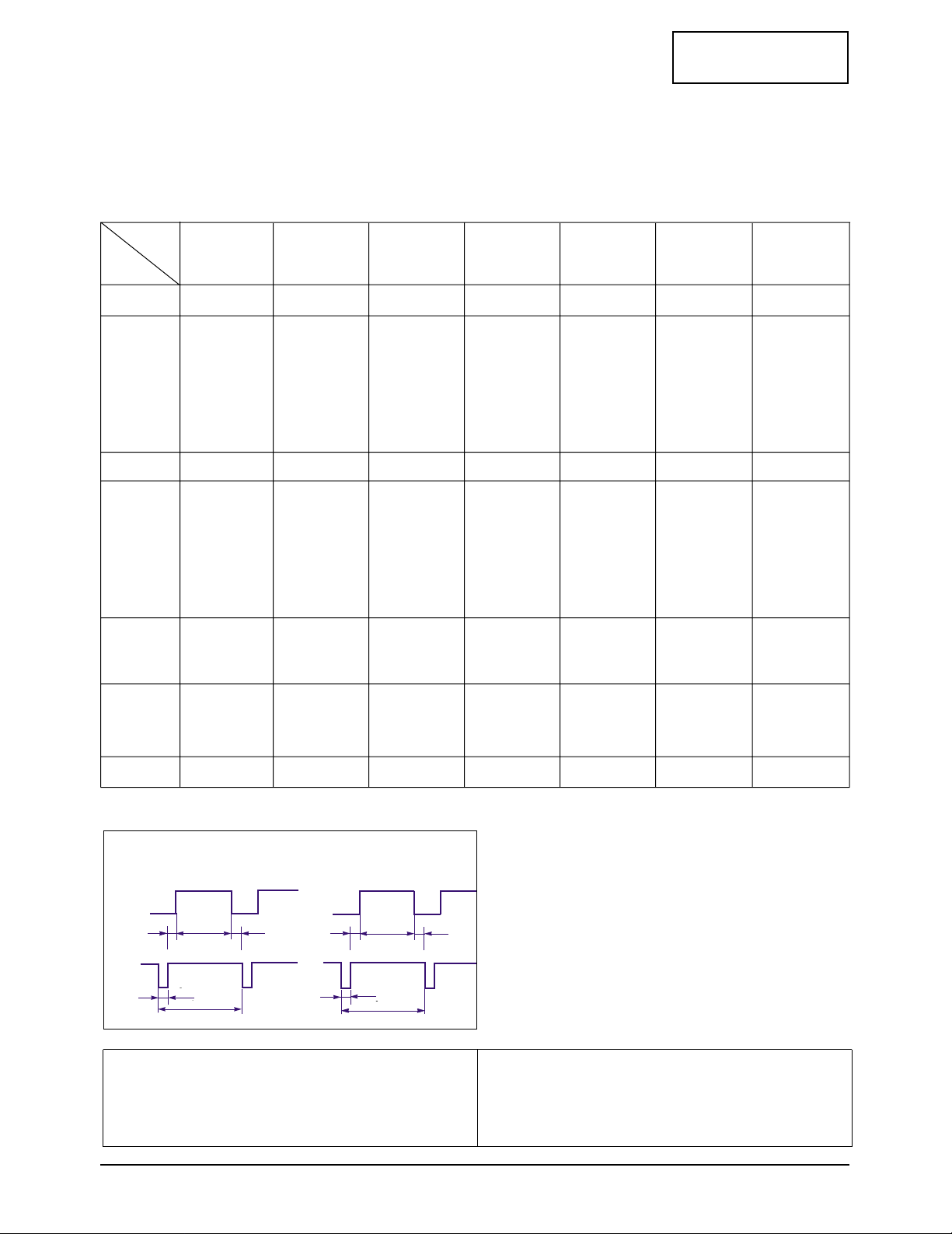
Mode
Timing
QRS
P
O
Video
Sync
Sync
Horizontal
Vertical
CDE
P
O
B
A
Video
Sync
Sync
Separate Sync
C D
A
O
E
B
P
Video
Sync
Sync
Video
Q R S
A : Line time total B : Horizontal sync width O : Frame time total P : Vertical sync width
C : Back porch D : Active time Q : Back porch R : Active time
E : Front porch S : Front porch
CONFIDENTIAL
2 Product Specifications
LTM295W/LTM405W 2-5
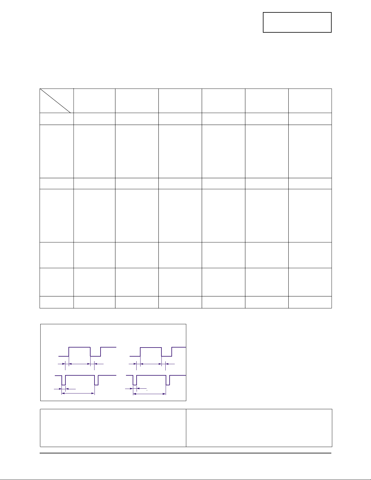
QRS
P
O
Video
Sync
Sync
Horizontal
Vertical
CDE
P
O
B
A
Video
Sync
Sync
Separate Sync
C D
A
O
E
B
P
Video
Sync
Sync
Video
Q R S
A : Line time total B : Horizontal sync width O : Frame time total P : Vertical sync width
C : Back porch D : Active time Q : Back porch R : Active time
E : Front porch S : Front porch
fH (kHz)
A µsec
B µsec
C µsec
D µsec
E µsec
fV (Hz)
O msec
P msec
Q msec
R msec
S msec
Clock
Frequency
(MHz)
Polarity
H.Sync
V.Sync
Remark
SUN/76 Hz
1280 x 1024
SXGA/60 Hz
1280 x 1024
SUN/76 Hz
1152 x 900
71.7
1472
96
208
1152
16
76.0
943
8
33
900
2
105.561
Negative
Negative
Separate
SUN/66 Hz
1152 x 900
61.8
1528
128
208
1152
40
66.0
937
4
31
900
2
94.500
–/+
–/+
Separate
64.0
1688
112
248
1280
48
60.0
1066
3
38
1024
1
108.000
Positive
Positive
Separate
74.4
1680
160
208
1280
32
70.0
1063
3
36
1024
0
125.000
Negative
Negative
Separate
80.0
1688
144
248
1280
16
75.0
1066
3
38
1024
1
135.000
Positive
Positive
Separate
81.1
1664
64
288
1280
32
76.1
1066
8
32
1024
2
135.000
Negative
Negative
Separate
SXGA/75 Hz
1280 x 1024
78.1
1728
192
192
1280
64
72.0
1085
3
55
1024
3
135.000
Negative
Negative
Separate
HP/72 Hz
1280 x 1024
NCD/70 Hz
1280 x 1024
Table 2-3 Timing Chart (continued)
Mode
Timing
CONFIDENTIAL
2 Product Specifications
2-6 LTM295W/LTM405W
QRS
P
O
Video
Sync
Sync
Horizontal
Vertical
CDE
P
O
B
A
Video
Sync
Sync
Separate Sync
C D
A
O
E
B
P
Video
Sync
Sync
Video
Q R S
A : Line time total B : Horizontal sync width O : Frame time total P : Vertical sync width
C : Back porch D : Active time Q : Back porch R : Active time
E : Front porch S : Front porch
Table 2-4 Timing Chart (continued)
fH (kHz)
A µsec
B µsec
C µsec
D µsec
E µsec
fV (Hz)
O msec
P msec
Q msec
R msec
S msec
Clock
Frequency
(MHz)
Polarity
H.Sync
V.Sync
Remark
UXGA/70Hz
1600 x 1200
UXGA/65Hz
1600 x 1200
81.25
2160
192
304
1600
64
65
1250
3
46
1200
1
175.500
–/+
–/+
Separate
UXGA/60Hz
1600 x 1200
75
2160
192
304
1600
64
60
1250
3
46
1200
1
162.000
–/+
–/+
Separate
87.5
2160
192
304
1600
64
70
1250
3
46
1200
1
189.000
–/+
–/+
Separate
80.038
2124
160
308
1600
56
64.443
1242
3
38
1200
1
170.000
–/+
–/+
Separate
74.52
2592
208
336
1920
128
60
1242
3
38
1200
1
193.156
Negative
Positive
Separate
WUXGA2/60 Hz
1920 x 1200
89.286
2240
256
368
1600
16
66.931
1334
10
44
1200
80
200.000
–/+
–/+
Separate
SUN/66 Hz
1600 x 1200
NCD/64Hz
1600 x 1200
Mode
Timing
CONFIDENTIAL
2 Product Specifications
LTM295W/LTM405W 2-7
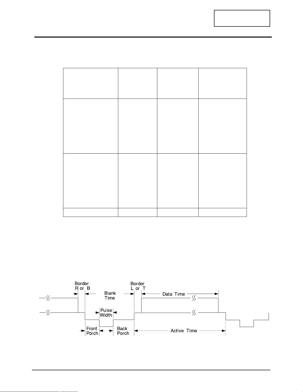
Table 2-5 DTV Timing chart
Timing No.
Originator
Mode Name
Resolution (HxV)
1
274M
1080i/60iHz
1920x1080
2
296M
720p/60Hz
1280x720
3
293M
480p/60Hz
720x483
HORIZONTAL
Frequency
Total time
Border (L / R)
Data time
Front porch
Sync. width
Back porch
Sync. polarity
33.750kHz
29.630
µs
0.000
µs
25.859
µs
0.593
µs
0.593
µs
2.586
µs
-
-
45.000kHz
22.222
µs
0.000
µs
17.239
µs
0.943
µs
0.539
µs
3.502
µs
-
31.469kHz
31.778
µs
0.000
µs
26.667
µs
0.593
µs
2.333
µs
2.185
µs
-
VERTICAL
Frequency
Total time
Border (T / B)
Data time
Front porch
Sync. width
Back porch
Sync. polarity
30Hz
33.333ms
0.000ms
0.059ms
0.148ms
0.444ms
-
60Hz
16.667ms
0.000ms
16.000ms
0.111ms
0.111ms
0.444ms
-
60Hz
16.683ms
0.000ms
15.349ms
0.191ms
0.191ms
0.953ms
-
Dot Clock 75MHz 75MHz 27MHz
2-4 DTV Timing Chart

Memo
2 Product Specifications
2-8 LTM295W/LTM405W
CONFIDENTIAL
LTM295W/LTM405W 3-1
CONFIDENTIAL
3 Disassembly and Reassembly
This section of the service manual describes the disassembly and reassembly procedures for the
LTM295W/LTM405W monitor.
WARNING: This monitor contains electrostatically sensitive devices. Use caution when handling
these components.
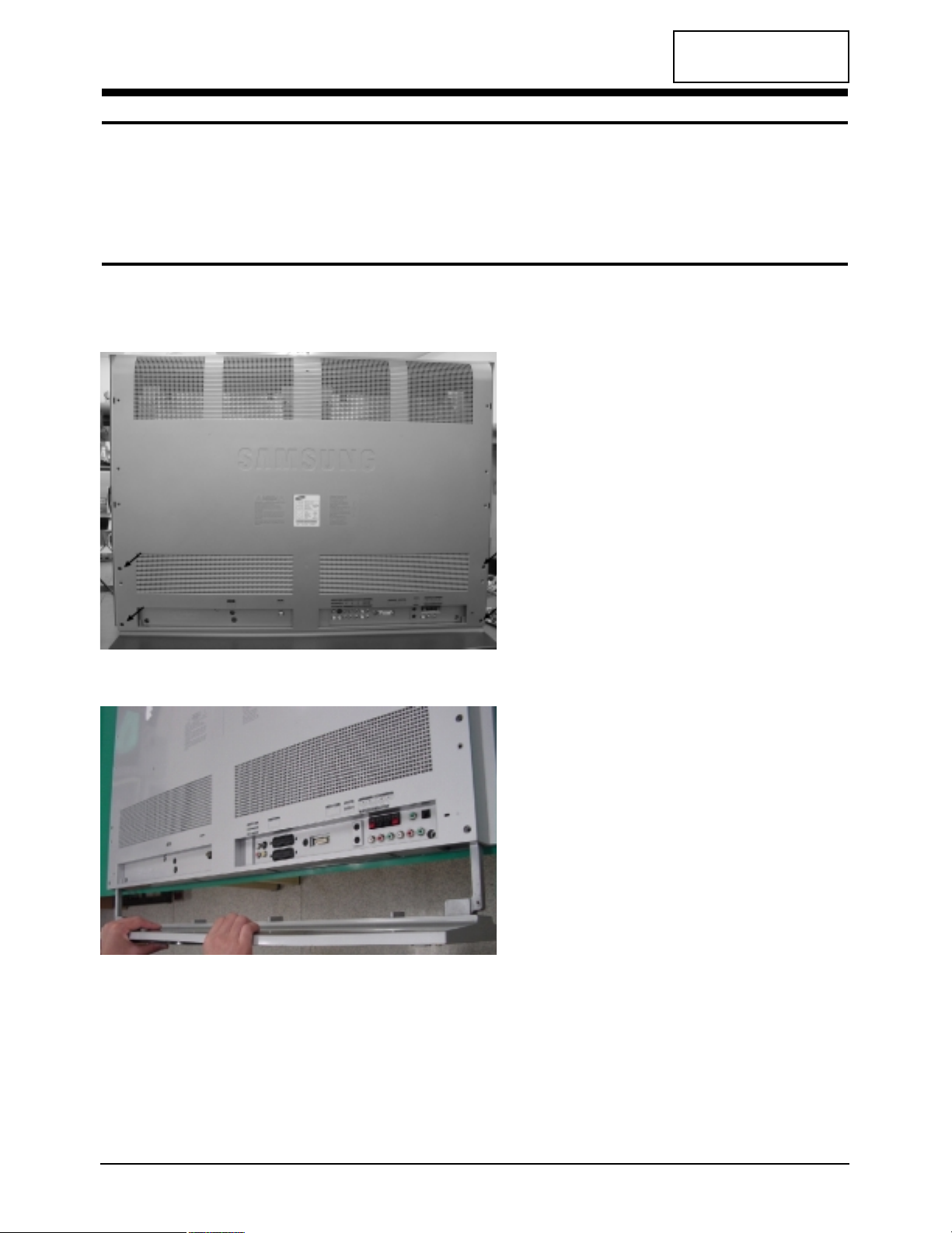
3-1 Disassembly
Cautions:1. Disconnect the monitor from the power source before disassembly.
2. Follow these directions carefully; never use metal instruments to pry apart the cabinet.
1. Remove 4 screws of the cover rear.
2. Remove the stand from LCD-TV.
3 Disassembly and Reassembly
3-2 LTM295W/LTM405W
CONFIDENTIAL
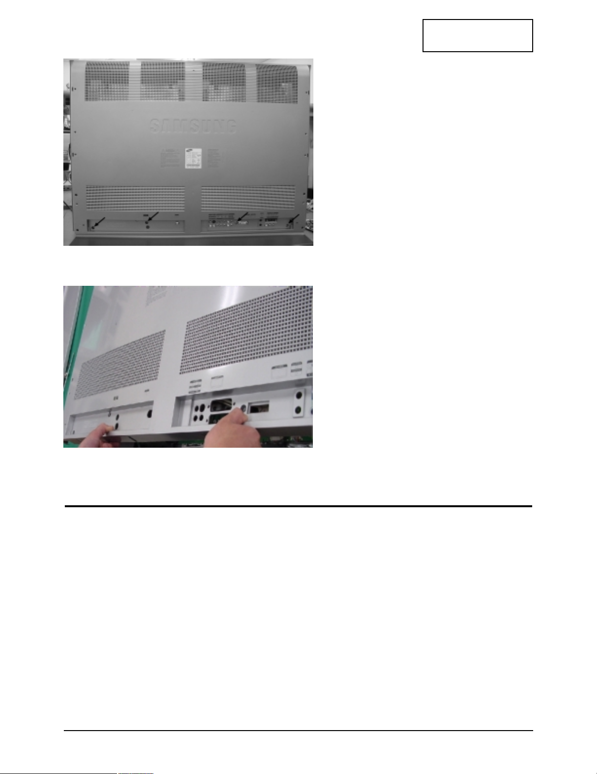
3. Remove 4 screws of the cover rear.
4. Pull the cover rear.
3-2 Reassembly
Reassembly procedures are in the reverse order of Disassembly procedures.

CONFIDENTIAL
LTM295W/LTM405W 4-1
4 Alignments and Adjustments
This section of the service manual explains how to use the DDC JIG to adjust the black, red, green, and blue
levels of the FPD when you replace the AD Board, and how to update the microprocessor when you
change the Panel or Lamp(s).
4-1 General Alignment Instuction
1. Usually, a color TV-VCR needs only slight touch-up adjustment upon installation.
Check the basic characteristics such as height, horizontal and vertical sync.
2. Use the specified test equipment or its equivalent.
3. Correct impedance matching is essential.
4. Avoid overload. Excessive signal from a sweep generator might overload the front-end
of the TV. When inserting signal markers,do not allow the marker generator to distort
test result.
5. Connect the TV only to an DC power source with voltage and frequency as specified on
the backcover nameplate.
6. Do not attempt to connect or disconnect any wire while the TV is turned on. Make sure
that the power cord is disconnected before replacing any parts.
7. To protect aganist shock hazard,use an isolation transform.

Memo
4 Alignments and Adjustments
4-2 LTM295W/LTM405W
CONFIDENTIAL
CONFIDENTIAL
LTM295W/LTM405W 5-1
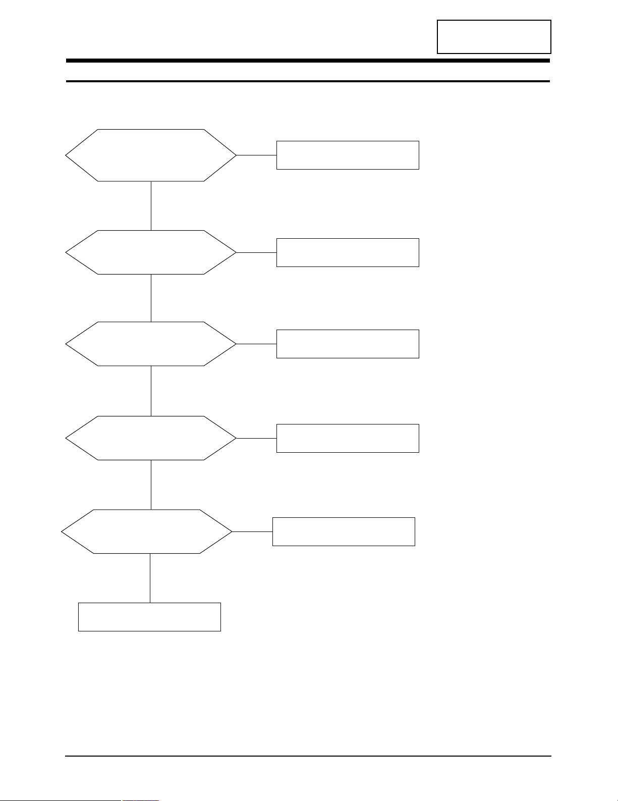
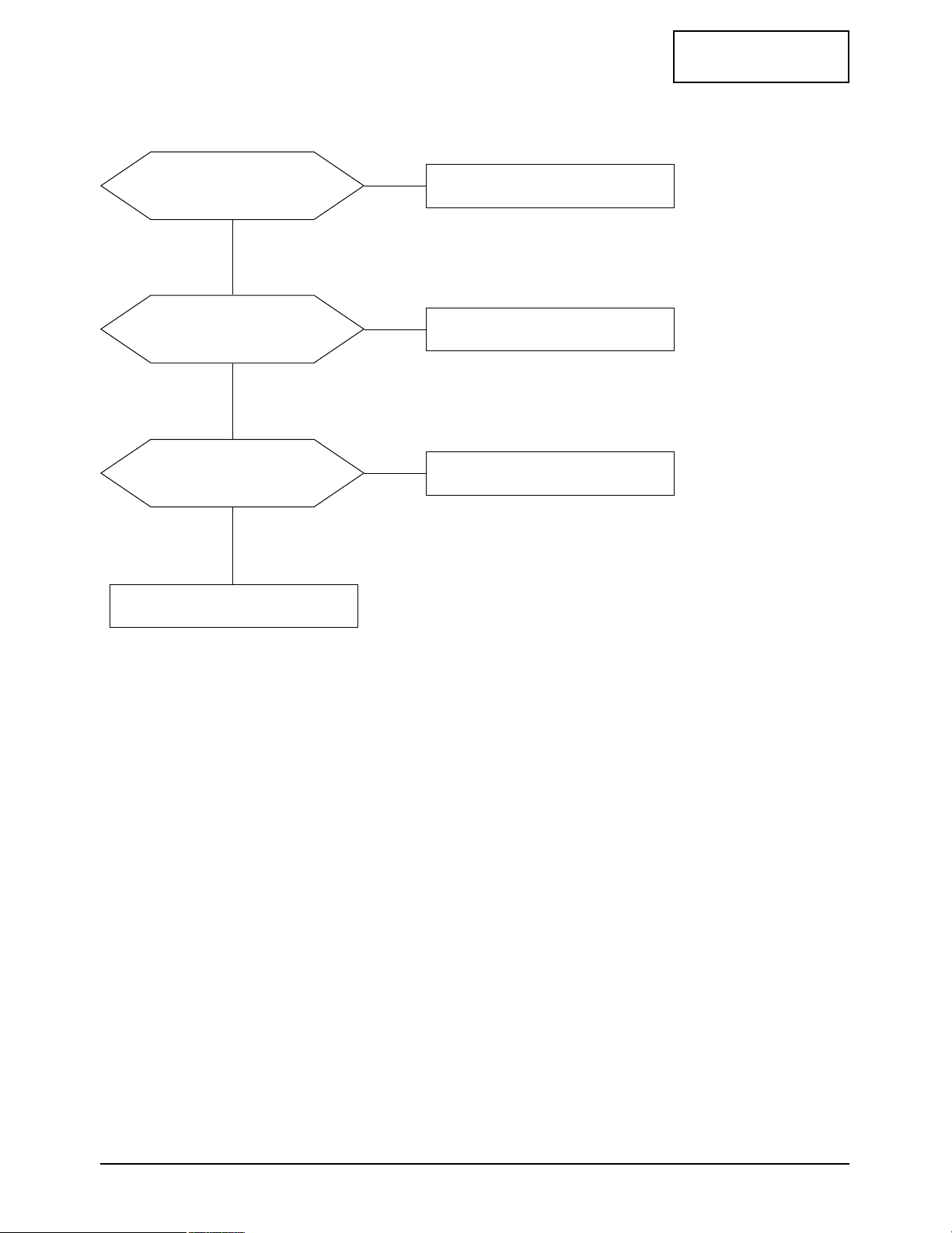
5 Troubleshooting
29”:Does proper DC 28 V appear
at DC jack connected to CN28?
40”:Does proper DC 28 V appear
at DC jack connected to CN29?
Check SMPS PCB and Adapter.
Yes
No
Does proper DC 5 V appear at
Pin 17 of CN201?
Check CN201 and related circuit.
Check IC963, IC906 and IC905.
Yes
No
Does proper DC 3.3 V
appear at Pin 2 of IC953,
IC954, IC956 and IC957?
Check IC953, IC954, IC956 and IC957
.
Yes
No
Does proper DC 2.5 V appear at
Pin 2 of IC961 and IC964?
Check IC961 and IC964.
Yes
No
Does proper DC 5 V appear at
Pin 2 of
IC952, IC955 and IC 958
?
Check IC952, IC955 and IC 958.
Yes
No
5-1 No Power
CONFIDENTIAL
5 Troubleshooting
5-2 LTM295W/LTM405W
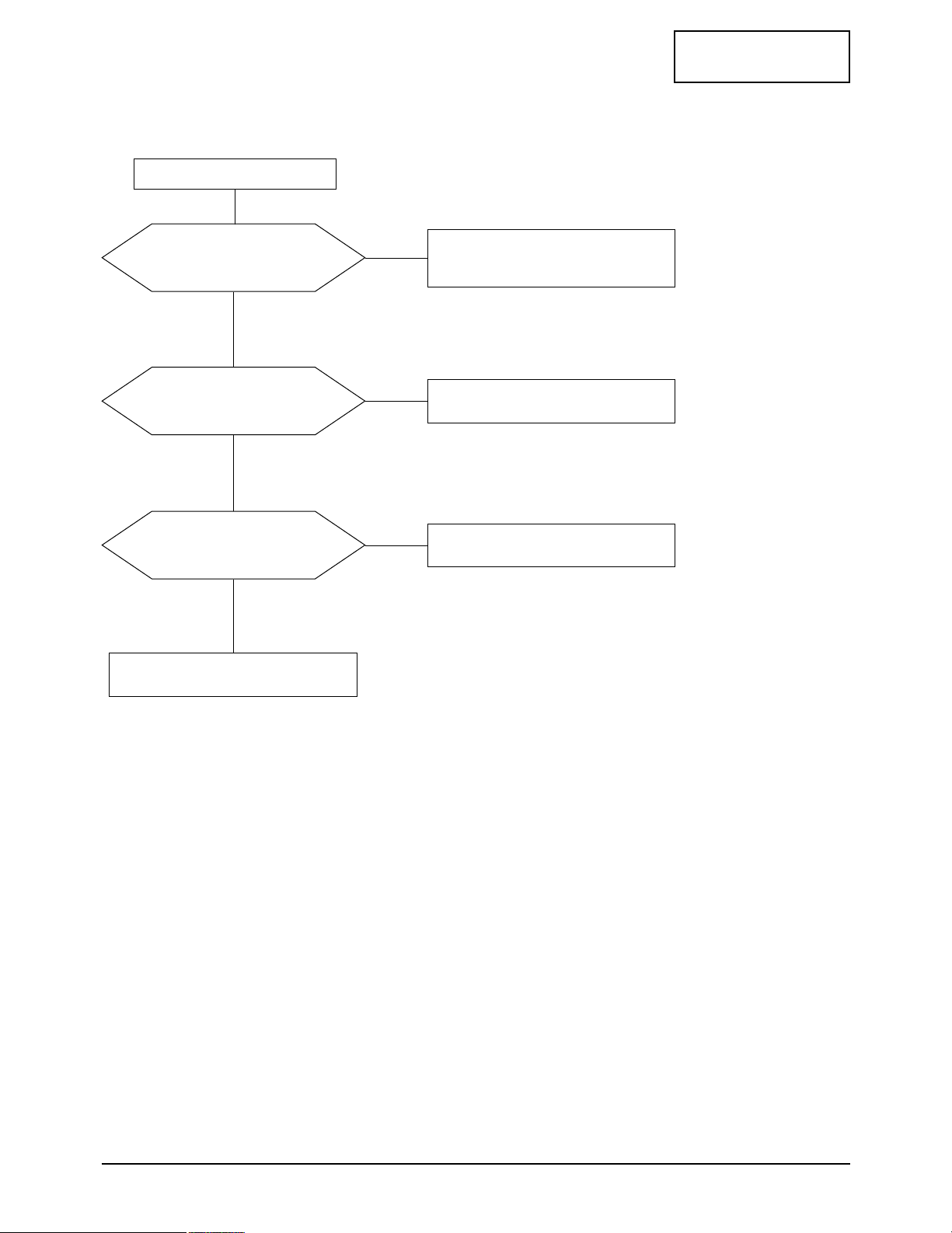
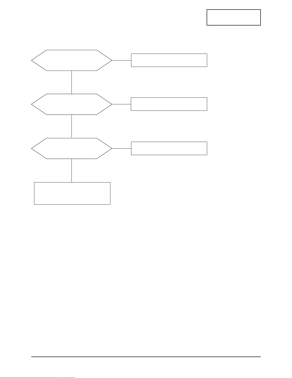
5-2 No Video (CVBS, S-Video)
Power indicator is green
Does the signal appear at
Pin 5, 9, 11 and 36 of IC1?
Check IC1.
Yes
No
Does the clock pulse appear at
Pin 6, 13 and Pin 69, 70 of IC302?
Check IC302 and related circuit.
Yes
No
Does the colck pluse
appear at R812, R813 and
H/V Sync pulse of IC801?
Check related circuit of IC801.
Yes
No
Replace LCD Panel.
CONFIDENTIAL
5 Troubleshooting
LTM295W/LTM405W 5-3
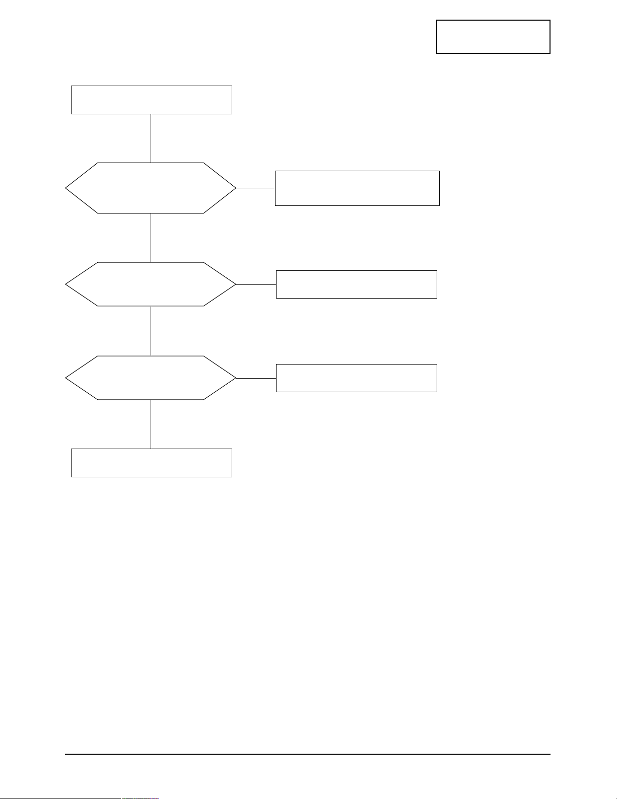
5-3 No Picture (PC Signal [Analog])
Check Pin 22 and 24 of CN201.
Check CN201 and related circuit.
Yes
No
Check Pin 66 and 67 of CN203.
Check IC203 and related circuit.
Yes
No
Does the colck pluse
appear at R619, R621 and
H/V Sync pulse of IC603?
Check IC603 and related circuit.
Yes
No
IC901 and IC903 and replace it.
CONFIDENTIAL
5 Troubleshooting
5-4 LTM295W/LTM405W
Does the signal appear at
Pin 47, 48, 50, 51, 53, 54, 56,
57 and 67 of IC503?
Check IC503 and related circuit.
Yes
No
Check Pin 10 and 13 of IC504?
Check IC504 and related circuit Q501.
Yes
No
Does the signal appear at
L502, L503, L504 and L505?
Replace L502, L503, L504 and L505.
Yes
No
29”:Check Speaker and CN2.
40”:Check Speaker and CN2.
5-4 No Sound (RF, PC, Video, Component)
CONFIDENTIAL
5 Troubleshooting
LTM295W/LTM405W 5-5
5-5 No Picture (DTV)
29”:Does the signal appear at
Pin 16, 18 and 20 of CN103?
40”:Does the signal appear at
Pin 16, 18 and 20 of CN3?
Check related circuit and
input signal of connector.
Yes
Yes
No
Dose the signal appear at
Pin 43, 48 and 54 of IC404?
Check IC404 and related circuit.
Yes
No
Dose the signal appear at
Pin 15, 19 and 21 of IC403?
Check IC403 and related circuit.
Yes
No
Check IC801 and related circuit.
Power inductor is green.

Memo
5 Troubleshooting
5-6 LTM295W/LTM405W
CONFIDENTIAL
CONFIDENTIAL
LTM295W/LTM405W 6-1
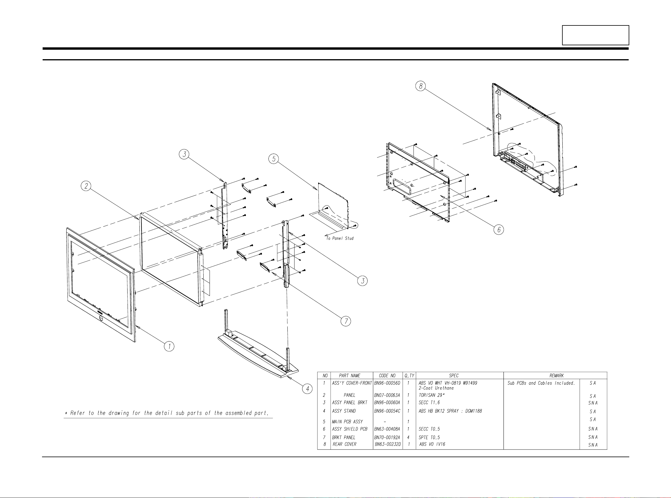
6 Exploded View and Parts List
6-1 LTM295W
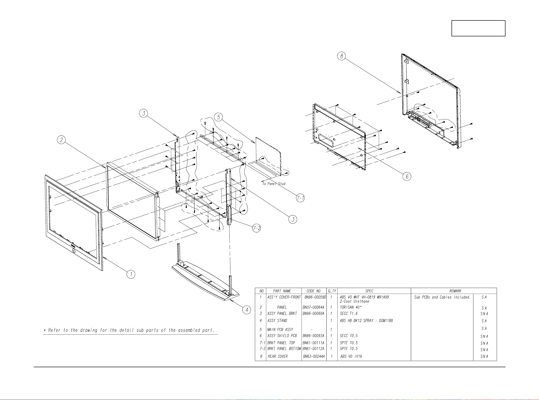
6-2 LTM405W
6 Exploded View & Parts List
6-2 LTM295W/LTM405W
CONFIDENTIAL

ItemNo DesignLOC 품명 Spec SERVICE
LTM295WX/XAA
RE-LTM295WX/XAA - 1 TORISAN,WX-71N31 BN90-00281A - ASSYSTAND AL29UO,U.S.A SNA
6003-001310 C/R+STAND SCREW-TAPTITE BH,+,B,M4,L16,ZPC(BLK),SWRCH18A SNA
BN96-00054C STD ASSYSTANDP APOLLO29,ABSVOGR81,DG-703P
BN90-00446A - ASSYCOVERFRONT AL29UO,U.S.A SNA
6003-000009 P/BRKT+C/F SCREW-TAPTITE BH,+,B,M4,L16,ZPC(YEL),SWRCH18 SNA
BN64-00101C C/F BADGE-BRAND AL29NO,AL,T1.5,11.5,65,DG-703P,SAMSUNG SNA
BN96-00056D C/F ASSYCOVERP-FRONT AL29UO,ABSVO,FORUSA
6003-001188 C/F SCREW-TAPTITE BH,+,B,M4,L10,YEL,SWRCH18A SNA
BN59-00290A C/F BOARD-FUNCTIONASS'Y AL29NO,CT5000-0600,FUNCTIONASS'Y
BN63-00230A C/F COVER-FRONT APOLLO29,ABS,V0,SILVER,SPRAY SNA
BN64-00061A C/F KNOB-RING APOLLO29,ABS,HB,CLEAR
BN64-00062A C/F KNOB-FUNCTION APOLLO29,ABS+PC,5V,SILVER
BN64-00101A C/F BADGE-BRAND APOLLO,AL,T1.5,11.5,65,SVM-2012,SAMSUNG SNA
BN67-00055A C/F LENS-LED APOLLO29,ACRYL,CLEAR SNA
BN67-00056A C/F LENS-MIRROR APOLLO29,ACRYL,CLEAR,ALCOATING
BN67-00070A C/F LENS-IR APOLLO29,ACRYL,CLEAR
BN90-00448A - ASSYCOVERREAR AL29UO,U.S.A SNA
6003-001003 C/F+C/R SCREW-TAPTITE BH,+,B,M4,L12,ZPC(BLK),SWRCH18
BN63-00232D C/R COVER-REAR AL29UO,ABS+PC,USA SNA
BN91-00388A - ASSYLCD AL29NO SNA
BN07-00063A CIS LCD TM290WX-71N31,RS24NS,6BITFRC,684.0*426.5*45.0,16.7M,40,0.4935*0.4935,040,5.0,T
BN91-00518A - ASSYMISC AL29/40UO,U.S.A SNA
BN44-00067C CIS ADAPTOR PSCV22101B,AMERICA,APPOLLO,100-240V,47-63HZ,28VDC,8ADC,224W,AMERICA,ULAREA
BN91-00552A - ASSYCHASSIS AL29UO,U.S.A
BN94-00403A - ASSYPCBMAIN AL29UO,U.S.A SNA
0202-001044 CIS01 SOLDER-WIRE. S63S-W3.0,S63S,D3,63Sn/37Pb,- SNA
0202-001172 CIS03 SOLDER-WIREFLUX RS-107,RS60,D1.2,SN60/PB40,- SNA
0204-001096 CIS04 ETHANOL ISO-PROPYLENE,C2H50H,99.8%,- SNA
0204-001527 CIS05 FLUX DF-201TVS,MIX,0.820,FLUX13%,14KG SNA
1001-001037 IC1 IC-RF/VI/AUDIOS/W TA8851CN,-,DIP,54P,600MIL,SING
2801-003224 X102 CRYSTAL-UNIT 32.768KHz,20ppm,28-AAY,12.5pF,
3711-003846 CN950 CONNECTOR-HEADER BOX,8P,1R,2mm,ANGLE,SN SNA
3711-004123 CN501 CONNECTOR-HEADER BOX,15P,1R,2mm,ANGLE,SN SNA
3711-004261 CN2 CONNECTOR-HEADER BOX,12P,1R,2MM,ANGLE,SN SNA
6001-000677 CIS06 SCREW-MACHINE RH,+,M3,L6,ZPC(YEL),SM20C,- SNA
BN27-00012A L901 COILCHOKE 5UH,APPOLO,5UH,10%,0.01OHMMAX,10A,PEI3210S,1T,40X70X25MM,BK,-10CTO+85C
BN73-00025A CIS07 RUBBERCUSHION AL29NO,CR,10*15,60,T4,BLACK,3M#9448 SNA
BN96-00093A CIS08 ASSYMISCP-SHIELD/D-SUB AL29NO,SPTET0.5 SNA
BN97-00164P CIS09 ASSYMICOM AL29UO,U.S.A
1102-001108 IC105 IC-EPROM 27C020,256Kx8Bit,PLCC,32P,495MIL,70nS,5V,10%,PLASTIC,0to+70C,100uA,CMOS,TR
BN82-00075U CIS A/SMICOM AL29UO,U.S.A SNA
BN97-00174A - ASSYSMD PD22EO,EUROPE SNA
Page1

0202-001162 CIS02 SOLDER-CREAM RMA-20-21L,S63,-,SN63/PB36.6/AG0.4,FLUX9.5% SNA
0401-001056 D1 DIODE-SWITCHING MMBD4148SE,75V,200MA,SOT-23,TP
0401-001056 D2 DIODE-SWITCHING MMBD4148SE,75V,200MA,SOT-23,TP
0401-001056 D3 DIODE-SWITCHING MMBD4148SE,75V,200MA,SOT-23,TP
0401-001056 D401 DIODE-SWITCHING MMBD4148SE,75V,200MA,SOT-23,TP
0401-001056 D402 DIODE-SWITCHING MMBD4148SE,75V,200MA,SOT-23,TP
0401-001056 D403 DIODE-SWITCHING MMBD4148SE,75V,200MA,SOT-23,TP
0401-001056 D404 DIODE-SWITCHING MMBD4148SE,75V,200MA,SOT-23,TP
0401-001056 D405 DIODE-SWITCHING MMBD4148SE,75V,200MA,SOT-23,TP
0401-001056 D406 DIODE-SWITCHING MMBD4148SE,75V,200MA,SOT-23,TP
0401-001056 D501 DIODE-SWITCHING MMBD4148SE,75V,200MA,SOT-23,TP
0401-001056 D502 DIODE-SWITCHING MMBD4148SE,75V,200MA,SOT-23,TP
0401-001056 D503 DIODE-SWITCHING MMBD4148SE,75V,200MA,SOT-23,TP
0401-001056 D504 DIODE-SWITCHING MMBD4148SE,75V,200MA,SOT-23,TP
0401-001056 D505 DIODE-SWITCHING MMBD4148SE,75V,200MA,SOT-23,TP
0401-001056 D506 DIODE-SWITCHING MMBD4148SE,75V,200MA,SOT-23,TP
0401-001056 D507 DIODE-SWITCHING MMBD4148SE,75V,200MA,SOT-23,TP
0401-001056 D508 DIODE-SWITCHING MMBD4148SE,75V,200MA,SOT-23,TP
0401-001056 D6 DIODE-SWITCHING MMBD4148SE,75V,200MA,SOT-23,TP
0401-001056 D7 DIODE-SWITCHING MMBD4148SE,75V,200MA,SOT-23,TP
0401-001056 D8 DIODE-SWITCHING MMBD4148SE,75V,200MA,SOT-23,TP
0401-001056 D9 DIODE-SWITCHING MMBD4148SE,75V,200MA,SOT-23,TP
0401-001116 D201 DIODE-SWITCHING BAV99DW,75V,150MA,SOT-363,TP
0401-001116 D202 DIODE-SWITCHING BAV99DW,75V,150MA,SOT-363,TP
0401-001116 D203 DIODE-SWITCHING BAV99DW,75V,150MA,SOT-363,TP
0401-001116 D204 DIODE-SWITCHING BAV99DW,75V,150MA,SOT-363,TP
0401-001116 D205 DIODE-SWITCHING BAV99DW,75V,150MA,SOT-363,TP
0401-001116 D206 DIODE-SWITCHING BAV99DW,75V,150MA,SOT-363,TP
0401-001116 D207 DIODE-SWITCHING BAV99DW,75V,150MA,SOT-363,TP
0401-001116 D208 DIODE-SWITCHING BAV99DW,75V,150MA,SOT-363,TP
0402-000553 ZD901 DIODE-RECTIFIER SS24,40V,2.0A,DO-214AA
0402-000553 ZD950 DIODE-RECTIFIER SS24,40V,2.0A,DO-214AA
0402-000553 ZD951 DIODE-RECTIFIER SS24,40V,2.0A,DO-214AA
0402-000553 ZD952 DIODE-RECTIFIER SS24,40V,2.0A,DO-214AA
0402-000553 ZD953 DIODE-RECTIFIER SS24,40V,2.0A,DO-214AA
0402-000553 ZD954 DIODE-RECTIFIER SS24,40V,2.0A,DO-214AA
0402-000553 ZD955 DIODE-RECTIFIER SS24,40V,2.0A,DO-214AA
0403-000579 ZD1 DIODE-ZENER BZX84C5V1,5.1V,5%,200mW,SOT-23
0403-000579 ZD2 DIODE-ZENER BZX84C5V1,5.1V,5%,200mW,SOT-23
0403-000579 ZD201 DIODE-ZENER BZX84C5V1,5.1V,5%,200mW,SOT-23
0403-000579 ZD202 DIODE-ZENER BZX84C5V1,5.1V,5%,200mW,SOT-23
0403-000579 ZD203 DIODE-ZENER BZX84C5V1,5.1V,5%,200mW,SOT-23
0403-000579 ZD204 DIODE-ZENER BZX84C5V1,5.1V,5%,200mW,SOT-23
0403-000579 ZD205 DIODE-ZENER BZX84C5V1,5.1V,5%,200mW,SOT-23
0403-000579 ZD206 DIODE-ZENER BZX84C5V1,5.1V,5%,200mW,SOT-23
0403-000579 ZD207 DIODE-ZENER BZX84C5V1,5.1V,5%,200mW,SOT-23
0403-000579 ZD208 DIODE-ZENER BZX84C5V1,5.1V,5%,200mW,SOT-23
Page2

0403-000579 ZD209 DIODE-ZENER BZX84C5V1,5.1V,5%,200mW,SOT-23
0403-000579 ZD210 DIODE-ZENER BZX84C5V1,5.1V,5%,200mW,SOT-23
0403-000579 ZD501 DIODE-ZENER BZX84C5V1,5.1V,5%,200mW,SOT-23
0403-000579 ZD505 DIODE-ZENER BZX84C5V1,5.1V,5%,200mW,SOT-23
0403-001052 ZD502 DIODE-ZENER RD8.2MB,8.2V,7.7-8.64V,200mW,S
0403-001052 ZD503 DIODE-ZENER RD8.2MB,8.2V,7.7-8.64V,200mW,S
0403-001052 ZD504 DIODE-ZENER RD8.2MB,8.2V,7.7-8.64V,200mW,S
0403-001052 ZD506 DIODE-ZENER RD8.2MB,8.2V,7.7-8.64V,200mW,S
0403-001052 ZD507 DIODE-ZENER RD8.2MB,8.2V,7.7-8.64V,200mW,S
0404-001055 D902 DIODE-SCHOTTKY -,60V,3000MA,SMC,TP
0404-001055 D903 DIODE-SCHOTTKY -,60V,3000MA,SMC,TP
0404-001084 D901 DIODE-SCHOTTKY BAT54A,30V,200MA,SOT-23,TP
0501-000280 Q1 TR-SMALLSIGNAL KSA1182,PNP,150mW,SOT-23,TP,70
0501-000280 Q10 TR-SMALLSIGNAL KSA1182,PNP,150mW,SOT-23,TP,70
0501-000280 Q11 TR-SMALLSIGNAL KSA1182,PNP,150mW,SOT-23,TP,70
0501-000280 Q13 TR-SMALLSIGNAL KSA1182,PNP,150mW,SOT-23,TP,70
0501-000280 Q16 TR-SMALLSIGNAL KSA1182,PNP,150mW,SOT-23,TP,70
0501-000280 Q4 TR-SMALLSIGNAL KSA1182,PNP,150mW,SOT-23,TP,70
0501-000280 Q5 TR-SMALLSIGNAL KSA1182,PNP,150mW,SOT-23,TP,70
0501-000280 Q7 TR-SMALLSIGNAL KSA1182,PNP,150mW,SOT-23,TP,70
0501-000280 Q8 TR-SMALLSIGNAL KSA1182,PNP,150mW,SOT-23,TP,70
0501-002080 Q101 TR-SMALLSIGNAL 2SC2412K,NPN,200mW,SC-59,TP,120-270
0501-002080 Q12 TR-SMALLSIGNAL 2SC2412K,NPN,200mW,SC-59,TP,120-270
0501-002080 Q14 TR-SMALLSIGNAL 2SC2412K,NPN,200mW,SC-59,TP,120-270
0501-002080 Q15 TR-SMALLSIGNAL 2SC2412K,NPN,200mW,SC-59,TP,120-270
0501-002080 Q2 TR-SMALLSIGNAL 2SC2412K,NPN,200mW,SC-59,TP,120-270
0501-002080 Q3 TR-SMALLSIGNAL 2SC2412K,NPN,200mW,SC-59,TP,120-270
0501-002080 Q301 TR-SMALLSIGNAL 2SC2412K,NPN,200mW,SC-59,TP,120-270
0501-002080 Q501 TR-SMALLSIGNAL 2SC2412K,NPN,200mW,SC-59,TP,120-270
0501-002080 Q6 TR-SMALLSIGNAL 2SC2412K,NPN,200mW,SC-59,TP,120-270
0501-002080 Q901 TR-SMALLSIGNAL 2SC2412K,NPN,200mW,SC-59,TP,120-270
0501-002080 Q906 TR-SMALLSIGNAL 2SC2412K,NPN,200mW,SC-59,TP,120-270
0501-002080 Q950 TR-SMALLSIGNAL 2SC2412K,NPN,200mW,SC-59,TP,120-270
0501-002080 Q951 TR-SMALLSIGNAL 2SC2412K,NPN,200mW,SC-59,TP,120-270
0501-002080 Q952 TR-SMALLSIGNAL 2SC2412K,NPN,200mW,SC-59,TP,120-270
0501-002080 Q953 TR-SMALLSIGNAL 2SC2412K,NPN,200mW,SC-59,TP,120-270
0501-002080 Q954 TR-SMALLSIGNAL 2SC2412K,NPN,200mW,SC-59,TP,120-270
0501-002080 Q955 TR-SMALLSIGNAL 2SC2412K,NPN,200mW,SC-59,TP,120-270
0501-002080 Q956 TR-SMALLSIGNAL 2SC2412K,NPN,200mW,SC-59,TP,120-270
0505-000275 IC905 FET-SILICON SI4435DY,P,-30V,+-8.0A,0.014ohm,2.5W,SO-8
0505-001170 IC963 FET-SILICON SI9933ADY-T1,P,-20V,3.4A,0.06ohm,2W,SO-8
0505-001662 Q904 FET-SILICON FDB5645,N,60V,80A,0.0095OHM,125W,TO-263AB
0505-001662 Q905 FET-SILICON FDB5645,N,60V,80A,0.0095OHM,125W,TO-263AB
0505-001663 Q902 FET-SILICON FQB50N06L,N,60V,52.4,0.021OHM,3.75W,D-PAK
0505-001663 Q903 FET-SILICON FQB50N06L,N,60V,52.4,0.021OHM,3.75W,D-PAK
0801-002267 IC205 IC-CMOSLOGIC 74LCX14,-,SOIC,14P,150MIL,-,TP,-,-,-,3.6V,-40TO+85C,-,5.5V,-,-,24MA
0801-002267 IC604 IC-CMOSLOGIC 74LCX14,-,SOIC,14P,150MIL,-,TP,-,-,-,3.6V,-40TO+85C,-,5.5V,-,-,24MA
Page3

0801-002268 IC110 IC-CMOSLOGIC 74VHC139,DECODER,SOP,16P,150MI
0801-002394 IC107 IC-CMOSLOGIC 74LCX32,ORGATE,SOIC,14P,150MI
0801-002394 IC112 IC-CMOSLOGIC 74LCX32,ORGATE,SOIC,14P,150MI
0801-002559 IC104 IC-CMOSLOGIC 74LVX74,DFLIP-FLOP,TSSOP,14P,173MIL,DUAL,TP,PLASTIC,-,-,0.36V,-40to+85C,180mW,2
0801-002559 IC405 IC-CMOSLOGIC 74LVX74,DFLIP-FLOP,TSSOP,14P,173MIL,DUAL,TP,PLASTIC,-,-,0.36V,-40to+85C,180mW,2
0801-002574 IC106 IC-CMOSLOGIC 74LVX04,INVERTER,SOP,14P,150MIL,HEX,TP,PLASTIC,-,-,0.36V,-40to+85C,180mW,2.4V,20
0801-002576 IC109 IC-CMOSLOGIC 74LVX373,LATCH,SOP,20P,300MIL,OCTAL,TP,PLASTIC,3-STATE,-,0.36V,-40to+85C,180mW,2
0903-001202 IC103 IC-MICROCONTROLLER 80251G2,8Bit,PLCC,44P,653MIL,24MHz,TR,CMOS,PLASTIC,5V,1.5W,0to+70C,1KBYTE,-,24Bi SNA
0909-001037 IC111 IC-REALTIMECLOCK M41ST84YMQ6TR,64BIT,SO16,16P,21.21X14.22MM,400KHZ,TP,CMOS,PLASTIC,-,1W,-40TO+85C
1001-001082 IC306 IC-VIDEOSWITCH BA7657F,-,SOP,24P,300MIL,SINGL
1001-001082 IC403 IC-VIDEOSWITCH BA7657F,-,SOP,24P,300MIL,SINGL
1001-001146 IC304 IC-ANALOGSWITCH FST3257,BUSSWITCH&CMOS,SOP,16P,150MIL,QUAD,5.5V,-40to+85C,PLASTIC,-,15ohm,-,1001-001146 IC406 IC-ANALOGSWITCH FST3257,BUSSWITCH&CMOS,SOP,16P,150MIL,QUAD,5.5V,-40to+85C,PLASTIC,-,15ohm,-,1001-001146 IC701 IC-ANALOGSWITCH FST3257,BUSSWITCH&CMOS,SOP,16P,150MIL,QUAD,5.5V,-40to+85C,PLASTIC,-,15ohm,-,1001-001190 IC702 IC-ANALOGSWITCH FST16233MTD,BUSSWITCH,TSSOP,56P,240MIL,-,5.5V,-40TO+85C,PLASTIC,-,20OHM,8.5NS,7
1002-001292 IC203 IC-A/DCONVERTER AD9883AKST-110,8BITS,QFP,80P,551MIL,±0.5LSB,TR,CMOS,PLASTIC,3.3V,-25TO+85C,650M
1002-001292 IC404 IC-A/DCONVERTER AD9883AKST-110,8BITS,QFP,80P,551MIL,±0.5LSB,TR,CMOS,PLASTIC,3.3V,-25TO+85C,650M
1103-000129 IC207 IC-EEPROM 24C02,256x8BIT,SOP,8P,150MIL,1
1103-001223 IC102 IC-EEPROM 24C16,2048x8Bit,SOP,8P,150MIL,10mS,2.7V,-,PLASTIC,0to+70C,4uA,CMOS,TP
1105-001336 IC601 IC-DRAM 4S643232,512Kx32x4Bit,TSOP,86P,400MIL,60nS,3.3V,10%,PLASTIC,0to+70C,2mA,CMOS,TP
1105-001336 IC602 IC-DRAM 4S643232,512Kx32x4Bit,TSOP,86P,400MIL,60nS,3.3V,10%,PLASTIC,0to+70C,2mA,CMOS,TP
1105-001336 IC704 IC-DRAM 4S643232,512Kx32x4Bit,TSOP,86P,400MIL,60nS,3.3V,10%,PLASTIC,0to+70C,2mA,CMOS,TP
1105-001336 IC802 IC-DRAM 4S643232,512Kx32x4Bit,TSOP,86P,400MIL,60nS,3.3V,10%,PLASTIC,0to+70C,2mA,CMOS,TP
1105-001336 IC803 IC-DRAM 4S643232,512Kx32x4Bit,TSOP,86P,400MIL,60nS,3.3V,10%,PLASTIC,0to+70C,2mA,CMOS,TP
1201-001495 IC505 IC-AUDIOAMP 7050,SOP,8P,150MIL,DUAL,26DB,PLASTIC,6V,0.25W,-,40DB,-,-,20NA,1201-001681 IC504 IC-AUDIOAMP 1101,SOP,30P,433MIL,-,-,PLASTIC,13.2V,-,0to+70C,-,-,-,-,-,TP
1203-001432 IC904 IC-POSI.FIXEDREG. 78M12,DPAK,3P,-,PLASTIC,11.5/1
1203-001448 IC901 IC-SWITCHVOL.REG. 2596,TO-263,5P,-,PLASTIC,4.750
1203-001448 IC951 IC-SWITCHVOL.REG. 2596,TO-263,5P,-,PLASTIC,4.750
1203-001448 IC952 IC-SWITCHVOL.REG. 2596,TO-263,5P,-,PLASTIC,4.750
1203-001448 IC955 IC-SWITCHVOL.REG. 2596,TO-263,5P,-,PLASTIC,4.750
1203-001448 IC958 IC-SWITCHVOL.REG. 2596,TO-263,5P,-,PLASTIC,4.750
1203-001465 IC950 IC-POSI.ADJUSTREG. 317,TO-263,3P,-,PLASTIC,1.2/37
1203-001465 IC961 IC-POSI.ADJUSTREG. 317,TO-263,3P,-,PLASTIC,1.2/37
1203-001465 IC964 IC-POSI.ADJUSTREG. 317,TO-263,3P,-,PLASTIC,1.2/37
1203-001488 IC502 IC-POSI.FIXEDREG. 7805,T0-252,3P,-,PLASTIC,4.8/5
1203-001559 IC101 IC-RESET DS1834,SOIC,8P,150MIL,-,1.2/5V
1203-001815 IC959 IC-POSI.FIXEDREG. 78M09,TO-252,3P,-,PLASTIC,8.6/9.4V,1.0W,-40TO+85C,0.5A,-,TP
1203-001815 IC960 IC-POSI.FIXEDREG. 78M09,TO-252,3P,-,PLASTIC,8.6/9.4V,1.0W,-40TO+85C,0.5A,-,TP
1203-001816 IC501 IC-POSI.FIXEDREG. 78M08,TO-252,3P,-,PLASTIC,7.7/8.3V,1.0W,-40TO+85C,0.5A,-,TP
1203-002067 IC201 IC-POSI.FIXEDREG. 3330,SOT-23,6P,65MIL,PLASTIC,3.284/3.316V,-,-40to+125C,200mA,-,TP
1203-002067 IC202 IC-POSI.FIXEDREG. 3330,SOT-23,6P,65MIL,PLASTIC,3.284/3.316V,-,-40to+125C,200mA,-,TP
1203-002067 IC206 IC-POSI.FIXEDREG. 3330,SOT-23,6P,65MIL,PLASTIC,3.284/3.316V,-,-40to+125C,200mA,-,TP
1203-002067 IC401 IC-POSI.FIXEDREG. 3330,SOT-23,6P,65MIL,PLASTIC,3.284/3.316V,-,-40to+125C,200mA,-,TP
1203-002067 IC402 IC-POSI.FIXEDREG. 3330,SOT-23,6P,65MIL,PLASTIC,3.284/3.316V,-,-40to+125C,200mA,-,TP
1203-002191 IC906 IC-DC/DCCONVERTER LTC1778,SSOP,16P,153MIL,PLASTIC,-,-,125C,-,-,TP
1203-002199 IC962 IC-POSI.FIXEDREG. LM2596,TO-263,5P,340MIL,PALSTIC,-,-,-40TO+125C,-,-,ST
Page4
 Loading...