

Page 1
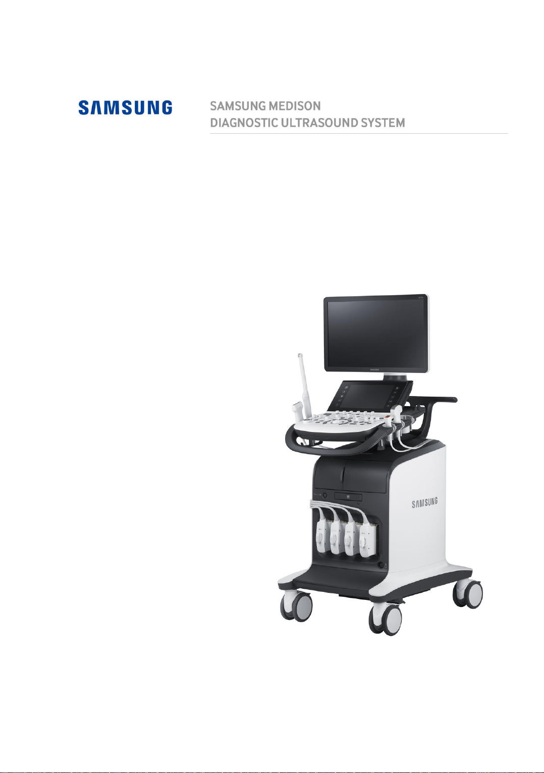
HS70A
Service Manual
Page 2

(Empty page)
Page 3

HS70A
Service Manual
English
SM-HS70A-ENG-02
Page 4

(Empty page)
Page 5

Safety Requirements
■ Classifications
− Type of protection against electric shock: Class I
− Degree of protection against electric shock (when the patient is in physical
contact): Type BF or CF applied part
− Degree of protection against harmful ingress of water: Ordinary equipment
− Degree of safety of application in the presence of a flammable anesthetic
material with air or with oxygen or nitrous oxide: Equipment not suitable for
use in the presence of a flammable anesthetic mixture with air or with
oxygen or nitrous oxide.
− Mode of operation: Continuous operation
■ „ Electromechanical safety standards met
− Medical Electrical Equipment, Part 1: General Requirements for Basic
Safety and Essential Performance IEC 60601-1:2005/A1:2012
− Medical Electrical Equipment, Part 1-2: General Requirements for Basic
Safety and Essential Performance - Collateral Standards: Electromagnetic
Compatibility - Requirements and Tests IEC 60601-1-2:2007
− Medical Electrical Equipment, Part 1-6: General Requirements for Basic
Safety and Essential Performance - Collateral Standards: Usability IEC
60601-1-6:2010
− Medical Electrical Equipment, Part 2-37: Particular Requirements for the
Basic Safety and Essential Performance of Ultrasonic Medical Diagnostic
and Monitoring Equipment IEC 60601-2-37:2007
− Medical Electrical Equipment, Part 1: General Requirements for Safety IEC
60601-1:1988, A1:1991, A2:1995
− Medical Electrical Equipment, Part 1-1: General Requirements for Safety -
Collateral Standards: General Requirements for Medical Electrical Systems
IEC 60601-1-1:2000
− Medical Electrical Equipment, Part 1-2: General Requirements for Safety -
Collateral Standards: Electromagnetic Compatibility - Requirements and
Tests IEC 60601-1-2:2001, A1:2004
− Medical Electrical Equipment, Part 1-4: General Requirements for Safety -
Collateral Standards: Programmable Electrical Medical Systems IEC
60601-1-4:1996, A1:1999
Page 6

− Medical Electrical Equipment, Part 2-37: Particular Requirements for the
CSA mark with the indicators “C” and “US” means
that the product is certified for both the U.S. and
Canadian markets, to the applicable U.S. and
Canadian standards.
This is the manufacturer’s declaration of product
compliance with applicable EEC directive (s) and the
European notified body.
This is the manufacturer’s declaration of product
compliance with applicable EEC directive (s).
This is the GMP symbol for Korean Good
Manufacturing Practice quality system regulation.
Basic Safety and Essential Performance of Ultrasonic Medical Diagnostic
and Monitoring Equipment IEC 60601-2-37:2001, A1:2004, A2:2005
− Medical Devices - Application of Risk Management ISO 14971:2007
− Medical Electrical Equipment, Part 1: General Requirements for Safety UL
60601-1:2003
− Medical Electrical Equipment - Part 1: General Requirements for Safety
CAN/CSA C22.2 No. 601.1-M90:1990, R2003, R2005
− Biological Evaluation of Medical Devices – Part 1: Evaluation and Testing
ISO 10993-1: 2009
− Standard Means for Reporting the Acoustic Output of Medical Diagnostic
Ultrasonic Equipment IEC 61157:2007
■ „ Declarations
Page 7
Precautions for Use
DANGER
Describes precautions necessary to prevent user hazards of great
urgency. Ignoring a DANGER warning will risk life-threatening
injury.
WARNING
Used to indicate the presence of a hazard that can cause serious
personal injury, or substantial property damage.
CAUTION
Indicates the presence of a hazard that can cause equipment
damage.
NOTE
A piece of information useful for installing, operating and
maintaining a system. Not related to any hazard.
Read this service manual to familiarize yourself thoroughly with repair procedures
and important safety information before attempting to service the product.
■ Refer to this service manual when you are servicing the product. Please
familiarize yourself with the safety precautions in 'Chapter 1. Safety' and
'Chapter 4. Maintenance' in particular.
■ This product is an ultrasound diagnosis device and cannot be used for other
purposes.
■ This product may only be serviced by a service engineer of Samsung Medison
or an authorized engineer. Samsung Medison is not responsible for any
problems caused by an unauthorized person servicing the product.
■ The manufacturer is not responsible for any damage to this product caused by
user carelessness and/or neglect.
■ The content of this service manual is subject to change without prior notice.
■ Products that are not manufactured by Samsung Medison are indicated with the
trademarks of their respective owners.
■ The following terms are used to highlight safety precautions that the user must
be aware of:
Page 8
Revision History
VERSION
DATE
REASON FOR CHANGE
v1.00.00
2015.07.07
Initial Release
V2.00.00
2016.09.22
Software upgrade / Parts change
The revision history of this manual is as follows:
If You Need Assistance
If you need any assistance with the equipment, please contact the Samsung
Medison Customer Service Department or your local vendor.
Page 9

This document is the technical property of SAMSUNG MEDISON CO., LTD. Using this
document without prior permission or for purposes other than repairs of the products of
Samsung Medison without approval may be subject to legal actions.
Page 10

Table of Contents 1
Table of Contents
Chapter 1. Safety
Purpose of Use ....................................................................................................................... 2
Contraindications ............................................................................................................. 2
Safety Information .................................................................................................................. 3
Safety Symbols ................................................................................................................ 3
Symbols ........................................................................................................................... 6
LABEL .............................................................................................................................. 6
Electrical Safety ...................................................................................................................... 7
Prevention of Electric Shocks .......................................................................................... 7
ECG-related Information .................................................................................................. 10
ESD ................................................................................................................................. 10
EMI .................................................................................................................................. 11
EMC ................................................................................................................................. 12
Mechanical Safety .................................................................................................................. 20
Moving the Equipment ..................................................................................................... 20
Safety Notes .................................................................................................................... 21
Biological Safety .................................................................................................................... 24
ALARA Principle .............................................................................................................. 24
Environmental Protection ..................................................................................................... 38
Chapter 2. Introduction
Product Specifications .......................................................................................................... 2
Product Configuration ........................................................................................................... 5
The Monitor ..................................................................................................................... 7
The Control Panel ............................................................................................................ 9
The Console .................................................................................................................... 16
Peripheral Devices........................................................................................................... 18
Page 11

2 HS70A Service Manual
Probes ............................................................................................................................. 21
Accessories ..................................................................................................................... 22
Optional Functions .......................................................................................................... 22
Chapter 3. Installing the Product
Transporting ........................................................................................................................... 2
Unpacking the Product ......................................................................................................... 3
Installation Environment ....................................................................................................... 4
Installing the Product ............................................................................................................ 5
Connecting Peripherals ................................................................................................... 7
System Power ........................................................................................................................ 9
Turning the Power On ..................................................................................................... 9
Shutting Down the System .............................................................................................. 10
System Settings ..................................................................................................................... 11
General ........................................................................................................................... 12
Scan Mode ...................................................................................................................... 17
Display ............................................................................................................................. 20
Annotate .......................................................................................................................... 24
Peripheral Device Settings .............................................................................................. 29
User Defined Keys .......................................................................................................... 33
Network ........................................................................................................................... 35
DICOM Setup (optional) .................................................................................................. 37
Options ............................................................................................................................ 49
System Information ......................................................................................................... 51
Chapter 4. Product Inspection
Inspecting Functions ............................................................................................................. 2
Basic Inspections ............................................................................................................ 2
Detailed Inspections ........................................................................................................ 4
Page 12

Table of Contents 3
Chapter 5. Product Structure
Overview ................................................................................................................................. 3
System Block Diagram .......................................................................................................... 5
Basic Structure of UGEO HS70A .......................................................................................... 7
Overview .......................................................................................................................... 7
Ultrasound System Part ................................................................................................... 8
PC Part ............................................................................................................................ 9
User Interface Part .......................................................................................................... 10
AC to Power Module ........................................................................................................ 10
Ultrasound System Part ......................................................................................................... 10
PSA .................................................................................................................................. 10
Analog Control ................................................................................................................. 12
Beam Former Board ........................................................................................................ 14
CW Board ........................................................................................................................ 18
Back End Board ............................................................................................................... 21
PC Part .................................................................................................................................... 26
PC Module ....................................................................................................................... 26
Software DSC .................................................................................................................. 27
Rear Board ...................................................................................................................... 29
Power Supply ................................................................................................................... 30
User Interface Part ................................................................................................................. 32
Control Panel ................................................................................................................... 32
Docking CP Board ........................................................................................................... 33
Touch Panel .................................................................................................................... 34
Monitor ............................................................................................................................. 35
Interconnect Diagram ............................................................................................................ 36
Page 13

4 HS70A Service Manual
Chapter 6. Service Mode
Enter Installation Key ............................................................................................................ 2
System Information ............................................................................................................... 4
Windows Mode ...................................................................................................................... 5
Accessing method(Old) ................................................................................................... 5
ACCESSING METHOD(V2.01.00~) ............................................................................... 6
Admin Mode ........................................................................................................................... 7
Accessing method(Old) ................................................................................................... 7
ACCESSING METHOD(V2.01.00~) ............................................................................... 8
Admin Mode Functions ................................................................................................... 9
Adding and Deleting Options ............................................................................................... 13
Adding an Option ............................................................................................................ 14
Chapter 7. Troubleshooting
Power Issues .......................................................................................................................... 2
Power Does Not Turn On ................................................................................................ 2
Power Does Not Turn Off ................................................................................................ 2
Power Turns Off by Itself................................................................................................. 3
Monitor .................................................................................................................................... 4
Nothing Is Displayed on the Screen ................................................................................ 4
Screen is Discolored ....................................................................................................... 4
Error Messages ...................................................................................................................... 5
Error Occurs during Booting............................................................................................ 5
Image....................................................................................................................................... 6
2D Mode: There is No IMAGE ECHO or IMAGE FORMAT ............................................ 6
Lines (Noise) Appear in 2D Mode Image ........................................................................ 6
M, C, PW, CW Mode Trouble ......................................................................................... 6
Error Code .............................................................................................................................. 7
Page 14

Table of Contents 5
Chapter 8. Disassembly and Assembly
Caution .................................................................................................................................... 2
Preparation ...................................................................................................................... 2
Disassembling the Product ................................................................................................... 3
Front Cover Disassembly ................................................................................................ 3
Rear Cover Disassembly ................................................................................................. 5
Control Panel Disassembly.............................................................................................. 7
Monitor Disassembly ....................................................................................................... 8
Monitor Arm Disassembly ................................................................................................ 9
Assembling the Product ........................................................................................................ 11
Chapter 9. Probes
Probe ....................................................................................................................................... 2
Ultrasound Transmission Gel .......................................................................................... 9
Using Sheaths ................................................................................................................. 10
Probe Safety Precautions ................................................................................................ 11
Cleaning and Disinfecting the Probe ............................................................................... 13
Chapter 10. Maintenance
Product Maintenance ............................................................................................................. 2
Cleaning and disinfecting................................................................................................. 2
Air Filter Management ..................................................................................................... 4
Accuracy Checks ............................................................................................................. 5
Information Maintenance ....................................................................................................... 6
Backing up User Setting .................................................................................................. 6
Backing Up Patient Information ....................................................................................... 6
Software........................................................................................................................... 6
Page 15

6 HS70A Service Manual
Chapter 11. Service Part List
Body Cover Parts ................................................................................................................... 2
System Parts .......................................................................................................................... 8
Control Panel Parts ............................................................................................................... 12
System Cable Parts ............................................................................................................... 16
Chapter 12. Parts Renewal
Board....................................................................................................................................... 2
Page 16

Chapter 1
Chapter 1. Safety
Safety
Purpose of Use ........................................................................................................... 2
Restrictions ............................................................................................................................... 2
Safety Information ...................................................................................................... 3
Safety Symbols ......................................................................................................................... 3
LABEL ....................................................................................................................................... 6
Electrical Safety .......................................................................................................... 7
Prevention of Electric Shock ..................................................................................................... 7
ECG-Related Information ....................................................................................................... 10
ESD ......................................................................................................................................... 10
EMI .......................................................................................................................................... 11
EMC ........................................................................................................................................ 12
Mechanical Safety ..................................................................................................... 20
Moving the Equipment ............................................................................................................ 20
Safety Notes ........................................................................................................................... 21
Biological Safety ....................................................................................................... 24
ALARA Principle ..................................................................................................................... 24
Environmental Protection ........................................................................................ 38
Page 17
1 - 2 HS70A Service Manual
NOTE
For detailed information on applications and presets, please refer to the
HS70A User Manual.
CAUTION
For information on the use or clinical application of this product, please
refer to the HS70A User Manual.
Purpose of Use
Ultrasound diagnostic system and probes were designed for obtaining ultrasound images and
analyzing human blood. The clinical applications include:
Fetal/Obstetrics, Abdominal, Gynecology, Pediatric, Small Organ, Neonatal Cephalic, Adult
Cephalic, Trans-rectal, Trans-vaginal, Muscular-Skeletal (Conventional, Superficial), Urology,
Cardiac Adult, Cardiac Pediatric and Peripheral vessel.
Restrictions
This product must not be used for ophthalmological applications, or any other use that involves the
ultrasound beam passing through the eye.
Page 18
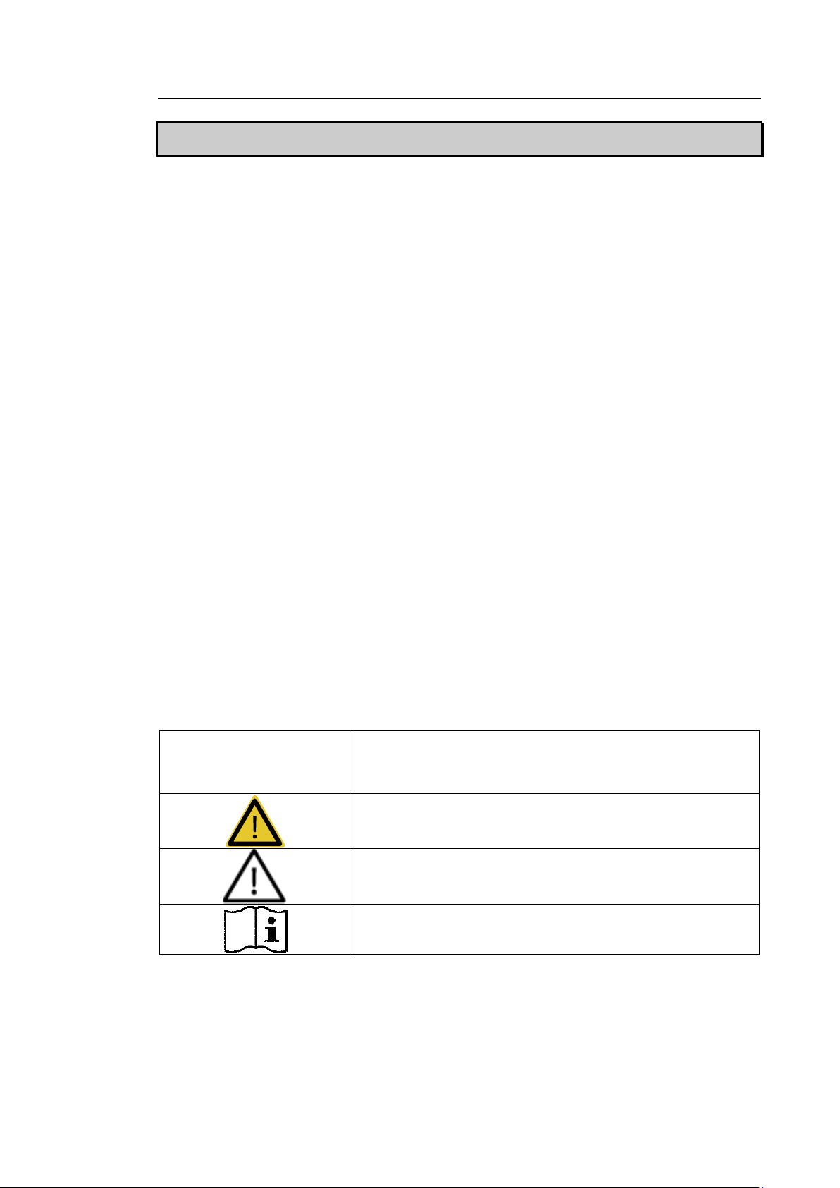
Chapter 1 Safety 1 - 3
Symbols
Description
Warning: The accompanying information must be followed to prevent
serious accidents and/or damage to property.
Caution: The accompanying information helps to prevent minor
accidents and/or damage to property.
Refer to the user manual.
Safety Information
Please read the following safety information before using this product. This provides explanation
about the ultrasound system, the probes, the recording devices, and any of the optional
equipment.
This product is intended for use by, or by the order of, and under the supervision of, a licensed
physician who is qualified for direct use of medical devices.
Prolonged use of three-dimensional ultrasound (3D, 4D) by an unqualified individual, such as to
produce a commemorative photograph or video of the fetus, may have an adverse effect on the
fetus.
Please use the 3D ultrasound diagnostic imaging system for appropriate purposes only, since
using it for non-diagnostic purposes such as recording videos of the fetus may adversely affect
the fetus.
Safety Symbols
The International Electro Technical Commission (IEC) has established a set of symbols for
medical electronic equipment, which classify a connection or warn of potential hazards. The
classifications and symbols are shown below.
Page 19
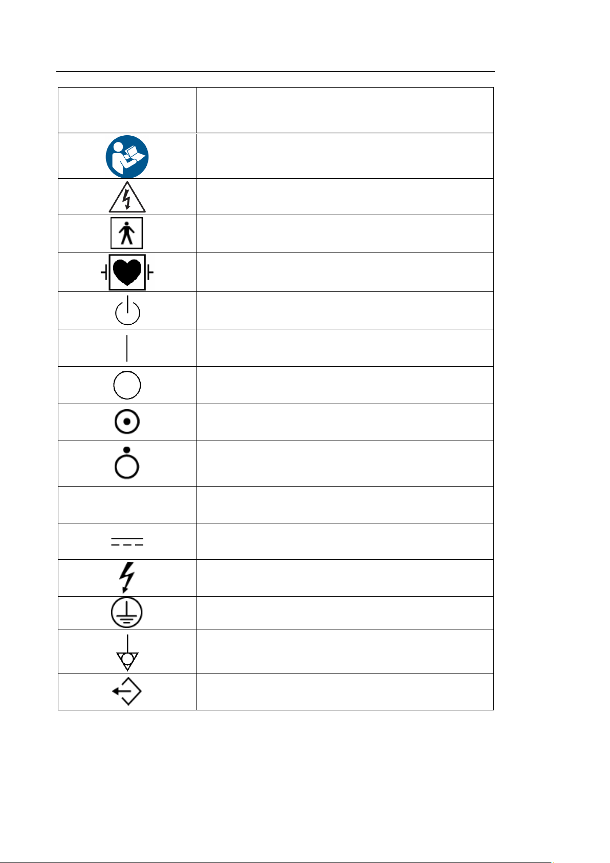
1 - 4 HS70A Service Manual
Symbols
Description
Follow the user manual.
Caution: Risk of electric shock
Type BF applied part (Classification based on degree of protection
against electric hazard)
Defibrillation-proof type CF applied part (Classification based on
degree of protection against electric hazard)
Power on/off
Power on
Power off
Product is partially powered on
Power off for part of the product
V~
AC (alternating current) voltage source
Direct current voltage source
Dangerous voltage (Indicates dangerous voltages over 1000V AC or
1500V DC)
Protective earth (ground)
Equipotentiality
Data output port
Page 20
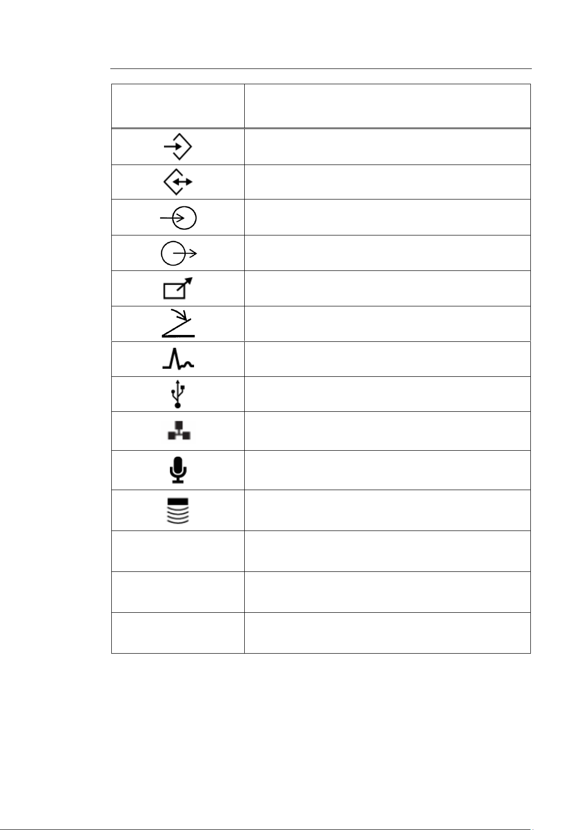
Chapter 1 Safety 1 - 5
Symbols
Description
Data input port
Data input/output port
Input port
Output port
Print remote output
Foot switch port
ECG port
USB port
Network port
Microphone port
Probe port
IPX 1
Dripping-proof device: Protected against vertically falling water
IPX 7
Immersion-proof device: Protected against the effects of temporary
immersion in water
IPX 8
Submersion-proof device: Protected against the effects of continuous
immersion in water
Page 21
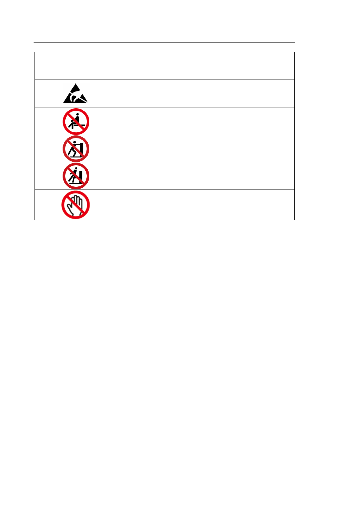
1 - 6 HS70A Service Manual
Symbols
Description
Caution: Electrostatic sensitive devices (ESD)
Do not sit on the product.
Do not push the product.
Do not lean against the product.
Be mindful of the space. Do not place a finger, and or any part of your
body in the space.
LABEL
Phrases containing the words ‘warning’ and/or ‘caution’ are displayed on the product’s surface
in order to protect it.
Page 22
Chapter 1 Safety 1 - 7
Electrical Safety
This equipment is categorized as a Class I device with Type BF or Type CF (ECG) applied parts.
Prevention of Electric Shock
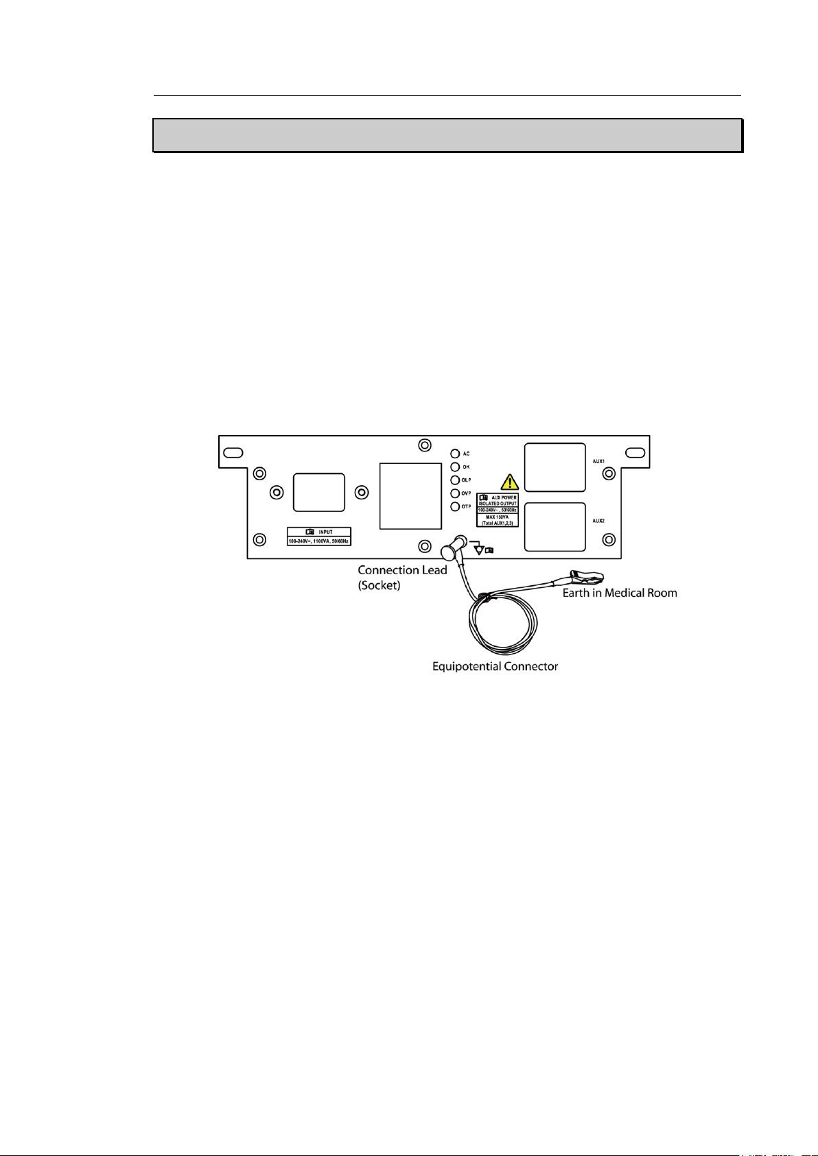
In a hospital environment, dangerous electric current may occur as a result of the potential
difference between a contactable conductive part and connected equipment in treatment rooms.
The solution to the problem is consistent equipotential bonding. Medical equipment is connected
with connecting leads made up of sockets which are angled to the equipotential bonding
network in medical rooms.
[Figure 1.1 Equipotential Bonding]
Additional equipment connected to medical electrical equipment must comply with the pertinent
IEC standards (e.g. IEC 60950/EN 60950 for data processing equipment, IEC 60601-1/EN
60601-1 for medical devices). Furthermore, all components of the product shall comply with the
requirements for medical electrical systems IEC 60601-1-1/EN 60601-1-1. Any person
connecting additional equipment to the signal input and output ports of medical electrical
equipment must verify that the equipment complies with IEC 60601-1-1/EN 60601-1-1.
Page 23

1 - 8 HS70A Service Manual
WARNING
■ Electric shocks may result if this system, including all of its externally
mounted recording and monitoring devices, is not properly grounded.
■ Never open the cover of the product. Hazardously high voltage flows
through the product. All internal adjustments and replacements must
be made by a qualified Samsung Medison Customer Service
Department.
■ Always check the product's casing, cables, cords, and plugs for
damage before using the product. Disconnect and do not use the
power source if the face is cracked, chipped, torn, the housing is
damaged, or if the cable is abraded.
■ Always disconnect the system from the wall outlet prior to cleaning it.
■ All patient contact devices, such as probes and ECG leads, must be
removed from the patient prior to the application of a high voltage
defibrillation pulse.
■ The use of flammable anesthetic gas or oxidizing gases (N2O) should
be avoided. Doing so may cause an explosion.
■ Avoid placing the system where it is likely to be difficult to operate, or
disconnect.
■ Do not use HF surgical equipment with the system. Any malfunctions
in the HF surgical equipment may result in burns to the patient.
■ The system must only be connected to a supply mains with protective
earth to avoid risk of electric shock.
Page 24

Chapter 1 Safety 1 - 9
CAUTION
■ The system has been designed for 100-240VAC; you should select the
input voltage of any connected printer and VCR. Prior to connecting a
peripheral power cord, verify that the voltage indicated on the power
cord matches the voltage rating of the peripheral device.
■ An isolation transformer protects the system from power surges. This
continues to operate when the system is on standby.
■ Do not immerse the cable in liquids. Cables are not waterproof.
■ Make sure that the inside of the system is not exposed to or flooded
with liquids. In such cases, fire, electric shock, injury, or damage to the
product may occur.
■ The auxiliary socket outlets installed on this system are rated 100-
240VAC, with a maximum total load of 150VA. Only use these outlets
for supplying power to equipment that is intended to be part of the
ultrasound system. Do not connect additional multiple-socket outlets or
extension cords to the system.
■ Do not connect any peripheral devices not listed in this manual to the
auxiliary socket outlets of the system. It may cause an electrical hazard.
■ Do not touch SIP/SOP and the patient simultaneously. There is a risk of
electric shock from current leakage.
Page 25

1 - 10 HS70A Service Manual
WARNING
■ This product does not support ECG monitoring. Therefore, it will not
recognize incompatible ECG signals.
■ Do not use the ECG electrodes of HF surgical equipment. Any
malfunctions in the HF surgical equipment may result in burns to the
patient.
■ Do not use ECG electrodes during cardiac pacemaker procedures or
other electrical stimulators.
■ Do not use ECG leads and electrodes in an operating room.
CAUTION
■ The level of electrical energy discharged from a system user or a patient
to an ultrasound system can be significant enough to cause damage to
the system or probes.
■ Always perform the pre-ESD preventive procedures before using
connectors marked with the ESD warning label.
- Apply anti-static spray to carpets or linoleum.
- Use anti-static mats.
- Ground the product to the patient table or bed.
■ It is highly recommended that the user be given training on ESD-related
warning symbols and preventive procedures.
ECG-Related Information
ESD
Electrostatic discharge (ESD), commonly referred to as a static shock, is a naturally occurring
phenomenon. ESD is most prevalent during conditions of low humidity, which can be caused by
heating or air conditioning. The static shock, or ESD, is a discharge of the electrical energy
buildup from a charged individual to a lesser or uncharged individual or object. An ESD occurs
when an individual with an electrical energy build-up comes in to contact with conductive objects
such as metal doorknobs, file cabinets, computer equipment, and even other individuals.
Page 26

Chapter 1 Safety 1 - 11
CAUTION
In cases where EMI is causing disturbances, it may be necessary to relocate
the system.
EMI
This product complies with EMI (Electromagnetic Interference) standards. However, using the
system inside an electromagnetic field can lower the quality of ultrasound images and even
damage the product.
If this occurs often, Samsung Medison suggests a review of the environment in which the
system is being used, to identify possible sources of radiated emissions. These emissions could
be from other electrical devices used within the same room or an adjacent room.
Communication devices, such as cellular phones and pagers, can cause these emissions. The
existence of radios, TVs, or microwave transmission equipment nearby can also cause
interference.
Page 27

1 - 12 HS70A Service Manual
Emission Test
Compliance
Electromagnetic environment guidance
RF Emission
CISPR 11
Group 1
The Ultrasound System uses RF energy only for its
internal function. Therefore, its RF emissions are very
low and are not likely to cause any interference in nearby
electronic equipment.
RF Emission
CISPR 11
Class A
The Ultrasound System is suitable for use in all
establishments other than domestic and those directly
connected to the public low-voltage power supply
network that supplies buildings used for domestic
purposes.
Harmonic Emission
IEC 61000-3-2
Class A
Flicker Emission
IEC 61000-3-3
Complies
EMC
Testing of the EMC (Electromagnetic Compatibility) of this system has been performed
according to the international standard for EMC with medical devices (IEC 60601-1-2). This IEC
standard was adopted in Europe as the European norm (EN 60601-1-2).
▐ Guidance and Manufacturer’s Declaration – Electromagnetic
Emissions
This product is intended for use in the electromagnetic environment specified below. The
customer or the user of this product should assure that it is used in such an environment.
Page 28
Chapter 1 Safety 1 - 13
Cable
Type
Length
VGA
Shielded
Normal
RS232C
Shielded
Normal
USB
Shielded
Normal
LAN(RJ45)
Twisted pair
Any
S-Video
Shielded
Normal
Foot Switch
Shielded
2.99m
B/W printer
Unshielded Coaxial
Normal
MIC
Unshielded
Any
Printer Remote
Unshielded
Any
Audio R.L
Shielded
Normal
VHS
Shielded
Normal
ECG AUX input
Shielded
< 3m
Parallel
Shielded
Normal
CAUTION
When connecting other customer-supplied accessories to the
system, it is the user’s responsibility to ensure the electromagnetic
compatibility of the system.
WARNING
The use of cables, probes, and peripherals other than those
specified, may result in increased emissions or decreased immunity
of the Ultrasound System.
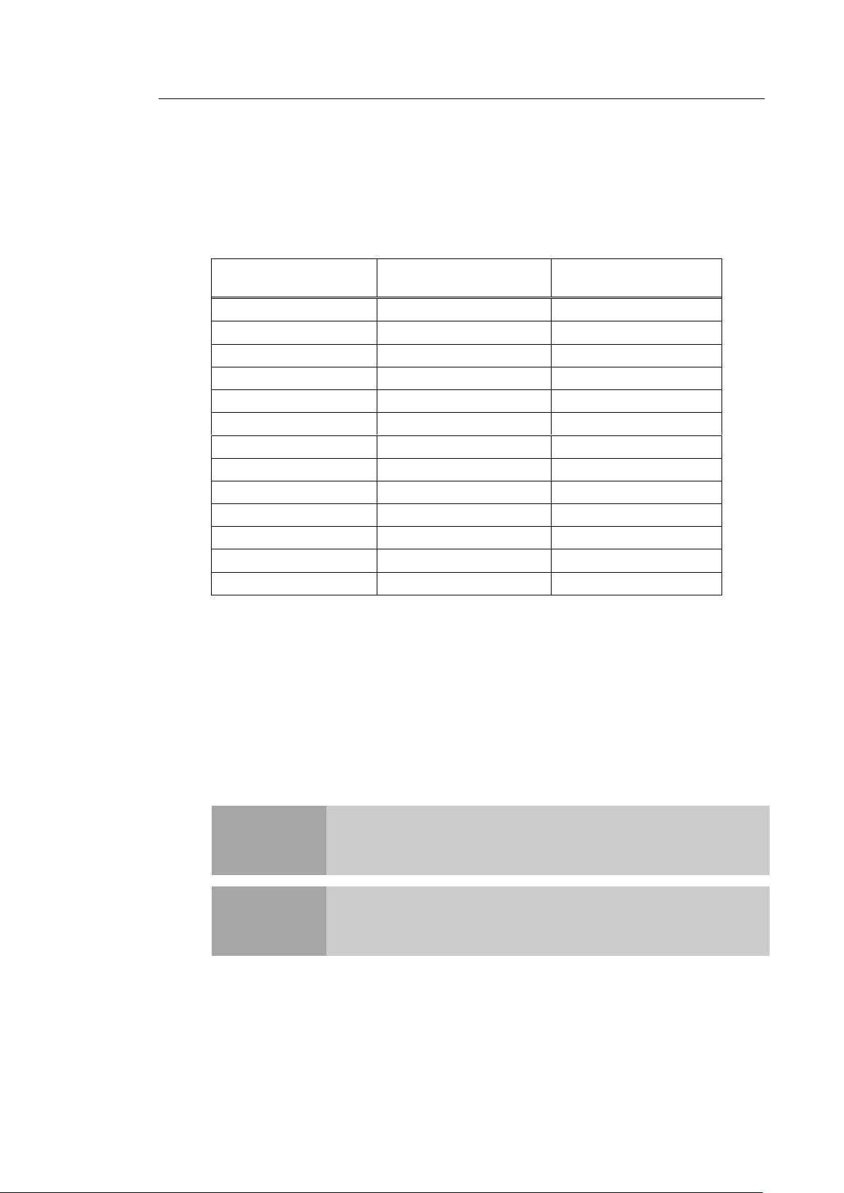
▐ Approved Cables, Probes and Peripherals for EMC
Cable
Cables connected to this product may affect its emissions.
Refer to the table below for recommended cable types and lengths:
Probe
The image probe used with this product may affect its emission. The probe listed in
‘Chapter 5. Probes’ when used with this product, have been tested to comply with the
group1 Class A emission as required by International Standard CISPR 11.
„ Peripherals
Peripherals used with this product may affect its emissions.
Page 29

1 - 14 HS70A Service Manual
Immunity Test
IEC 60601 Test
Level
Compliance level
Electromagnetic
environment guidance
Electrostatic
discharge (ESD)
IEC 61000-4-2
±6KV contact
±8KV air
±6KV contact
±8KV air
Floors should be wood,
concrete or ceramic tile.
If floors are covered with
synthetic material, the
relative humidity should be
at least 30%.
Electrical fast
transient/burst
IEC 61000-4-4
±2KV
for power supply lines
±1KV
for input/output lines
±2KV
for power supply lines
±1KV
for input/output lines
Mains power quality should
be that of a typical
commercial or hospital
environment.
Surge
IEC 61000-4-5
±1KV differential mode
±2KV common mode
±1KV differential mode
±2KV common mode
Mains power quality should
be that of a typical
commercial or hospital
environment.
Voltage dips,
short
interruptions and
voltage variations
on power supply
input lines
IEC 61000-4-11
<5% Uт for 0.5 cycles
(>95% dip in Uт)
40% Uт for 5 cycles
(60% dip in Uт)
70% Uт for 25 cycles
(30% dip in Uт)
<5% Uт for 5 s
(<95% dip in Uт)
<5%Uт for 0.5 cycles
(>95% dip in Uт)
40% Uт for 5 cycles
(60% dip in Uт)
70% Uт for 25 cycles
(30% dip in Uт)
<5%Uт for 5 s
(<95% dip in Uт)
Mains power quality should
be that of a typical
commercial or hospital
environment. If the user of
this product requires
continued operation during
power mains interruptions, it
is recommended that this
product be powered from an
uninterruptible power supply
or a battery.
Power frequency
magnetic field
(50/60Hz)
IEC 61000-4-8
3A/m
3A/m
Power frequency magnetic
fields should be at levels
characteristic of a typical
commercial or hospital
environment.
Note: Uт is the AC mains voltage, prior to application of the test level.
Page 30
Chapter 1 Safety 1 - 15
Immunity Test
IEC 60601 Test
Level
Compliance
level
Electromagnetic environment guidance
Conducted RF
IEC 61000-4-6
3Vrms
150kHz
~ 80MHz
3V
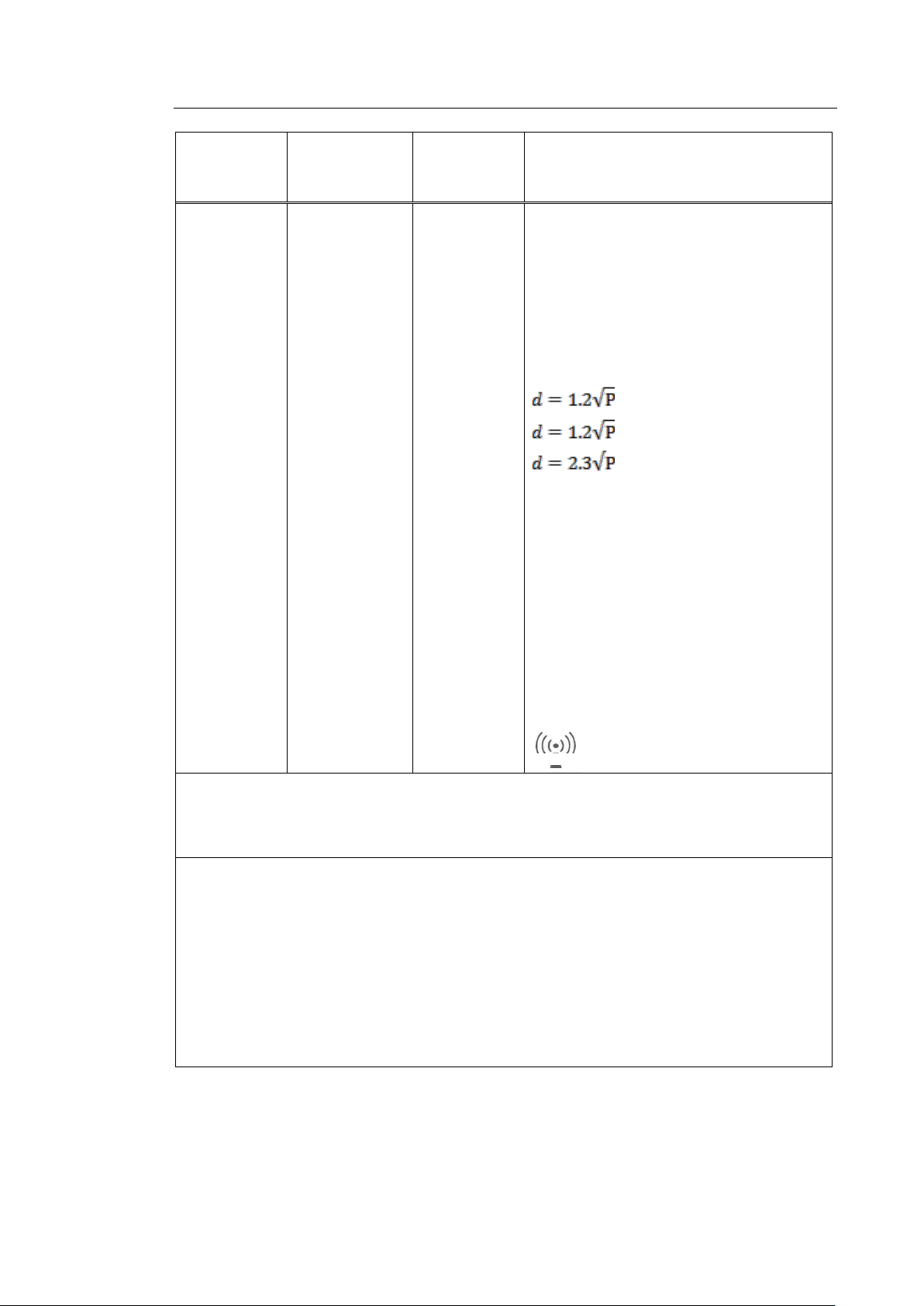
Portable and mobile RF communications
equipment should be used no closer to any
part of the Ultrasound System, including
cables, than the recommended separation
distance. This is calculated using the equation
applicable to the frequency of the transmitter.
Recommended separation distance
80MHz to 800MHz
800MHz to 2.5GHz
Radiated RF
IEC 61000-4-3
3V/m
80MHz
~ 2.5GHz
3V/m
Where P is the transmitter’s maximum output
power rating in watts (W) according to the
transmitter’s manufacturer, and d is the
recommended separation distance in meters
(m).
Field strengths from fixed RF transmitters, as
determined by an electromagnetic site survey,
a
should be less than the compliance level in
each frequency range.b
Interference may occur in the vicinity of
equipment marked with the following symbol:
Note 1) At 80MHz and 800MHz, the higher frequency range applies.
Note 2) These guidelines may not apply in all situations. Electromagnetic propagation is affected by
absorption and reflection from structures, objects and people.
a
Field strengths from fixed transmitters, such as base stations for radio, (cellular/cordless) telephones
and land mobile radios, amateur radio, AM and FM radio broadcasts and TV broadcasts cannot be
predicted with accuracy. To assess the electromagnetic environment due to fixed RF transmitters, an
electromagnetic site survey should be considered. If the measured field strength, in the location in
which the Ultrasound System is used, exceeds the applicable RF compliance level above, the
Ultrasound System should be observed to verify normal operation. If abnormal performance is
observed, additional measures may be necessary, such as reorienting or relocating the Ultrasound
System or using a shielded location with a higher RF shielding effectiveness and filter attenuation.
b
IOver the frequency range 150kHz to 80MHz, field strengths should be less than 3 V/m.
Page 31

1 - 16 HS70A Service Manual
Rated maximum
output power of
transmitter
W
Separation distance, according to frequency of transmitter m
150kHz ~ 80MHz
80MHz ~ 800MHz
800MHz ~ 2.5GHz
0.01
0.12
0.12
0.23
0.1
0.38
0.38
0.73
1
1.2
1.2
2.3
10
3.8
3.8
7.3
100
12
12
23
For transmitters rated at a maximum output power not listed above, the recommended separation
distance d in meters (m) can be estimated using the equation applicable to the frequency of the
transmitter, where p is the maximum output power rating of the transmitter in watts (W), according to
the transmitter’s manufacturer.
NOTE 1) At 80MHz and 800MHz, the separation distance for the higher frequency range applies.
NOTE 2) These guidelines may not apply in all situations. Electromagnetic propagation is affected
by absorption and reflection from structures, objects and people.
▐ Recommended Separation Distances between This Product
and RF Communications Equipment
This product is intended for use in an electromagnetic environment in which radiated RF
disturbances are controlled. The customer or the user of this product can help prevent
electromagnetic interference by maintaining a minimum distance between portable and
mobile RF communications equipment (transmitters) and this product. These distances are
recommended below, according to the maximum output power of the communications
equipment.
Page 32

Chapter 1 Safety 1 - 17
CAUTION
If the system is connected to other customer-supplied equipment, such as
a local area network (LAN) or a remote printer, Samsung Medison cannot
guarantee that the remote equipment will work correctly in the presence of
electromagnetic phenomena.
▐ Electromagnetic Environment – Guidance
It is recommended to use ultrasound systems in shielded locations offering RF shielding
effectiveness, with shielded cables. Field strengths outside the location shielded from fixed
RF transmitters, as determined by an electromagnetic site survey, should be less than 3V/m.
It is essential that the actual shielding effectiveness and filter attenuation of the shielded
location be verified to assure that they meet the minimum specification.
Page 33

1 - 18 HS70A Service Manual
Imaging Mode
ESD1
RF2
Power Line3
2D
Change of operating
mode, system settings,
or system reset.
Brief flashes in the
displayed or recorded
image.
For sector imaging
probes, white radial
bands or flashes in the
centerlines of the image.
For linear imaging
probes, white vertical
bands, sometimes more
pronounced on the sides
of the image.
White dots, dashes,
diagonal lines, or diagonal
lines near the center of the
image.
M
Increase in the image
background noise or
white M mode lines.
White dots, dashes,
diagonal lines, or increase
in image background
noise.
Color
Color flashes, radial or
vertical bands, increase
in background noise, or
changes in color image.
Color flashes, dots,
dashes, or changes in the
color noise level.
Doppler
Horizontal lines in the
spectral display or tones,
abnormal noise in the
audio, or both.
Vertical lines in the
spectral display, popping
type noises in the audio, or
both.
1. ESD caused by discharging of electric charge build-up on insulated surfaces or persons.
2. RF energy from RF transmitting equipment such as portable phones, hand-held radios, wireless
devices, commercial radio and TV, and so on.
3. Conducted interference on power lines or connected cables caused by other equipment, such as
switching power supplies, electrical controls, and natural phenomena such as lightning.
▐Avoiding Electromagnetic Interference
Typical interference on ultrasound imaging systems varies depending on electromagnetic
phenomena. Please refer to the following table:
A medical device can either generate or receive electromagnetic interference. The EMC
standards describe tests for both emitted and received interference.
Samsung Medison ultrasound systems do not generate interference in excess of the
referenced standards.
The Ultrasound System is designed to receive signals at radio frequency and is therefore
Page 34

Chapter 1 Safety 1 - 19
susceptible to interference generated by RF energy sources. Examples of other sources of
interference are medical devices, information technology products, and radio and television
transmission towers. Tracing the source of radiated interference can be a difficult task.
Customers should consider the following in an attempt to locate the source:
- Is the interference intermittent or constant?
- Does the interference show up only with one transducer operating at the same
frequency or with several transducers?
- Do two different transducers operating at the same frequency have the same problem?
- Is the interference present if the system is moved to a different location in the facility?
The answers to these questions will help to determine if the problem resides with the
system or the scanning environment. After you answer this question, contact your local
Samsung Medison customer service representative.
Page 35

1 - 20 HS70A Service Manual
WARNING
The product weighs more than 100kg. Be extra careful when transporting
it. Careless transportation of the product may result in product damage or
personal injury.
Mechanical Safety
Moving the Equipment
Before transporting the product, check that the wheel brakes are unlocked. Also, make
sure to retract the monitor arm completely, so that it is secured in a stationary position.
Always use the handles at the back of the console and move the product slowly.
This product is designed to resist shocks. However, excessive shock, for example – if the
product falls over, may cause serious damage.
If the product does not work properly after transfer, please contact the Samsung Medison
Service Department.
▐The Brakes
You can use the brakes to control the movement of the product. The brakes are mounted
on each wheel of the main body with interlinked on/off buttons. This is how you engage or
release the brakes:
- Engaged: To engage the brakes, press the On button with your foot. The Off button will
rise.
- Released: To release the brakes, press the Off button with your foot. The On button will
rise.
We recommend that you lock the brakes when using the product.
Page 36

Chapter 1 Safety 1 - 21
WARNING
Be aware of the castors, especially when moving the system. Samsung
Medison recommends that you exercise caution when moving the product
up or down ramps.
CAUTION
■ Do not press the control panel excessively.
■ Never attempt to modify the product in any way.
■ Check the operational safety when using the product after a prolonged
break in service.
■ Make sure that other objects, such as pieces of metal, do not enter the
system.
■ Do not block the ventilation slots.
■ Do not pull on the power cord to unplug it. Doing so can damage the
cord and cause short-circuiting and cord snapping. Always unplug by
pulling on the plug itself.
■ Excessive bending or twisting of cables, or parts that are applied to the
patient, may cause failure or intermittent operation of the system.
■ Improper cleaning or sterilization of parts that are applied to the patient
may cause permanent damage.
■ Servicing the product, including repairs and the replacement of parts,
must be done by qualified Samsung Medison service personnel.
Assuming that the product is used in accordance with the guidelines
contained in this manual and maintained by qualified service personnel,
the expected service life of the product is approximately 7 years.
▐Precautions on Ramps
Always make sure that the control panel is facing the direction of movement.
When moving the product down a ramp or resting it temporarily on a ramp, the product may
tilt over even with the brakes on depending on the direction the product is facing. Do not
leave the product on ramps.
Safety Notes
For detailed information on cleaning and disinfecting the product, refer to ‘Chapter 4.
Maintenance‘.
Page 37
1 - 22 HS70A Service Manual
CAUTION
■ Do not press on the control panel with excessive force or lean against it.
■ Do not sit on the control panel or apply too much pressure to it.
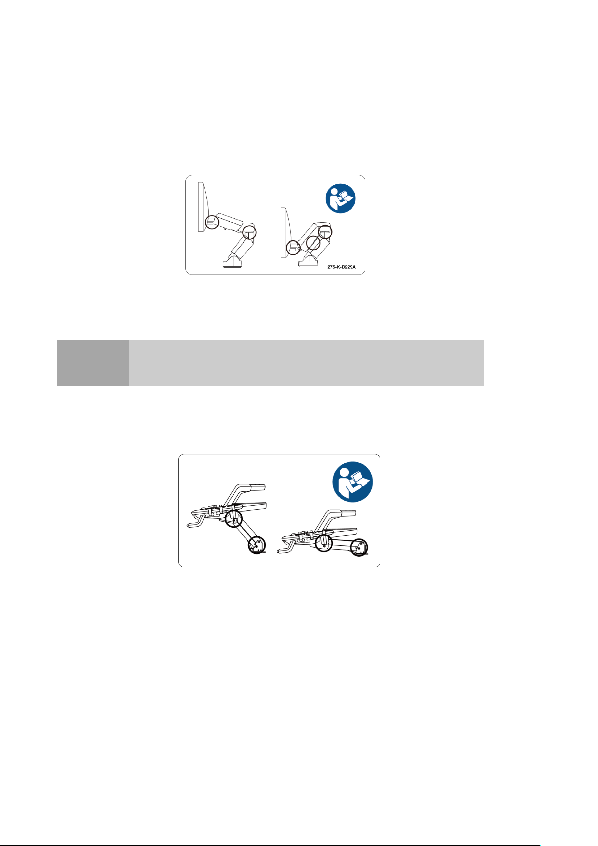
▐Monitor Safety Caution
When adjusting the height or position of the monitor, be careful of the space in the middle of
the monitor arm. Having your fingers, or other body parts, caught in it may result in injury.
[Figure 1.2 Monitor Safety Caution]
▐Control Panel Caution
When adjusting the control panel’s height or position, be mindful of the space between the
panel and the lift. Having your fingers, or other body parts, caught in it may result in injury.
[Figure 1.3 Control Panel Caution]
When using the handle of the control panel, be mindful of the space between the handle
and the keyboard. The keyboard may pop up and hit your hand.
Page 38

[Figure 1.4 Handle Caution]
Chapter 1 Safety 1 - 23
Page 39

1 - 24 HS70A Service Manual
WARNING
■ Ultrasound waves may have damaging effects on cells and, therefore, may
be harmful to the patient. If there is no medical benefit, minimize the
exposure time and maintain the ultrasound wave output level at low. Please
refer to the ALARA principle.
■ Do not use the system if an error message appears on the video display
indicating that a hazardous condition exists. Note the error code, turn off the
power to the system, and call Samsung Medison customer service
department.
■ Do not use a system that exhibits erratic or inconsistent functioning.
Discontinuities in the scanning sequence are indicative of a hardware failure
that should be corrected before use.
■ The system limits the maximum contact temperature to 43 degrees Celsius,
and the ultrasonic wave output observes American FDA regulations.
Biological Safety
For safety instructions concerning probes and biopsies, refer to HS70A User Manual.
ALARA Principle
Guidance for the use of diagnostic ultrasound is defined by the ”(As Low As Reasonably Achievable)
(ALARA) principle. The decision as to what is reasonable has been left to the judgment and insight of
qualified personnel. No set of rules can be formulated that would be sufficiently complete to dictate the
correct response to every circumstance. By keeping ultrasound exposure as low as possible, while
obtaining diagnostic images, users can minimize ultrasonic bioeffects.
Since the threshold for diagnostic ultrasound bioeffects is undetermined, it is the sonographer’s
responsibility to control the total energy transmitted into the patient. The sonographer must reconcile
exposure time with diagnostic image quality. To ensure diagnostic image quality and limit exposure time,
the Ultrasound System provides controls that can be manipulated during the exam to optimize the results.
The ability of the user to abide by the ALARA principle is important. Advances in diagnostic ultrasound, not
only in the technology but also in its applications, have resulted in the need for increased and improved
information to guide the user. The output indices are designed to provide that important information.
There are a number of variables, which affect the way in which the output display indices can be used to
implement the ALARA principle. These variables include mass, body size, location of the bone relative to
the focal point, attenuation in the body, and ultrasound exposure time. Exposure time is an especially
useful variable, because the user controls it. The ability to limit the index values over time supports the
ALARA principle.
Page 40

Chapter 1 Safety 1 - 25
▐Applying ALARA
The system imaging mode used depends upon the information needed. 2D-mode and M-mode imaging
provide anatomical information, while Doppler, Power, and Color imaging provide information about
blood flow. Scanned modes, like 2D-mode, Power, or Color, disperse or scatter the ultrasonic energy
over an area, while an unscanned mode, like M-mode or Doppler, concentrate the ultrasonic energy.
Understanding the nature of the imaging mode being used allows the sonographer to apply the ALARA
principle with informed judgment. The probe frequency, system set-up values, scanning techniques, and
operator experience aid the sonographer in meeting the ALARA principle. The decision as to the amount
of acoustic output is, in the final analysis, up to the system operator. This decision must be based on the
following factors: type of patient, type of exam, patient history, ease or difficulty of obtaining
diagnostically useful information, and the potential localized heating of the patient due to probe surface
temperatures. Prudent use of the system occurs when patient exposure is limited to the lowest index
reading for the shortest amount of time necessary to achieve acceptable diagnostic results.
Although a high index reading does not mean that a biological effect is actually occurring, it should be
taken seriously. Every effort should be made to reduce the possible effects of a high index reading.
Limiting exposure time is an effective way to accomplish this goal.
There are several system controls that the operator can use to adjust the image quality and limit the
acoustic intensity. These controls are related to the techniques that an operator might use to implement
ALARA and can be divided into three categories: direct, indirect, and receiver control.
▐Direct Controls
Application selection and the output intensity control directly affect acoustic intensity. There are different
ranges of allowable intensity or output depending on your selection. Selecting the correct range of
acoustic intensity for the application is one of the first things required during any exam. For example,
peripheral vascular intensity levels are not recommended for fetal exams. Some systems automatically
select the proper range for a particular procedure, while others require manual selection. Ultimately, the
user bears the responsibility for proper clinical use. Samsung Medison systems provide both
automatic and user-definable settings.
Output has direct impact on acoustic intensity. Once the application has been established, the output
control can be used to increase or decrease the output intensity. The output control allows you to select
intensity levels less than the defined maximum. Prudent use dictates that you select the lowest output
intensity consistent with good image quality.
▐Indirect Controls
The indirect controls are those that have an indirect effect on acoustic intensity. These controls affect
Page 41

1 - 26 HS70A Service Manual
imaging mode, pulse repetition frequency, focus depth, pulse length, and probe selection.
The choice of imaging mode determines the nature of the ultrasound beam. 2D-mode is a scanning
mode, Doppler is a stationary or unscanned mode. A stationary ultrasound beam concentrates energy
on a single location. A moving or scanned ultrasound beam disperses the energy over a wide area and
the beam is only concentrated on a given area for a fraction of the time that is necessary in unscanned
mode.
Pulse repetition frequency or rate refers to the number of ultrasound bursts of energy over a specific
period of time. The higher the pulse repetition frequency, the more pulses of energy in a given period of
time. Several controls affect pulse repetition frequency: focal depth, display depth, sample volume depth,
color sensitivity, number of focal zones, and sector width controls.
The focus of the ultrasound beam affects the image resolution. To maintain or increase resolution at a
different focus requires a variation of output over the focal zone. This variation of output is a function of
system optimization. Different exams require different focal depths. Setting the focus to the proper depth
improves the resolution of the structure of interest.
Pulse length is the time during which the ultrasonic burst is turned on. The longer the pulse, the greater
the time-average intensity value. The greater the time-average intensity, the greater the likelihood of
temperature increase and cavitations. Pulse length, burst length or pulse duration is the output pulse
duration in pulsed Doppler. Increasing the Doppler sample volume, increases the pulse length.
Probe selection affects intensity indirectly. Tissue attenuation changes with frequency. The higher the
probe operating frequency, the greater the attenuation of the ultrasonic energy. Higher probe operating
frequencies require higher output intensity to scan at an increased depth. To scan deeper at the same
output intensity, a lower probe frequency is required. Using more gain and output beyond a point,
without corresponding increases in image quality, can mean that a lower frequency probe is needed.
Receiver Controls
Receiver controls are used by the operator to improve image quality. These controls have no
effect on output. Receiver controls only affect how the ultrasound echo is received. These
controls include gain, TGC, dynamic range, and image processing. The important thing to
remember, relative to output, is that receiver controls should be optimized before increasing
output. For example; before increasing output, optimize gain to improve image quality.
▐Additional Considerations
Ensure that scanning time is kept to a minimum, and ensure that only medically required scanning is
performed. Never compromise quality by rushing through an exam. A poor exam will require a follow-
Page 42

Chapter 1 Safety 1 - 27
up, which ultimately increases the time. Diagnostic ultrasound is an important tool in medicine, and,
like any tool, should be used efficiently and effectively.
▐Output Display Features
The system output display comprises two basic indices: a mechanical index and a thermal index. The
thermal index consists of the following indices: soft tissue (TIs), bone (TIb) and cranial bone (TIc). One
of these three thermal indices will be displayed at all times. Which one depends upon the system’s
default setting or user choice, depending upon the application at hand.
The mechanical index is continuously displayed over the range of 0.0 to 1.9, in increments of 0.1. The
thermal index consists of the three indices, and only one of these is displayed at any one time. Each
probe application has a default selection that is appropriate for that combination. The TIb or TIs is
continuously displayed over the range of 0.0 to the maximum output, based on the probe and
application, in increments of 0.1.
The application-specific nature of the default setting is also an important factor of index behavior. The
default setting is a system control state, which is preset by the manufacturer or the operator. The
system has default index settings for the probe application. The default settings are invoked
automatically by the Ultrasound System when power is turned on, new patient data is entered into the
system database, or a change in application takes place. The decision as to which of the three
thermal indices to display should be based on the following criteria:
Appropriate index for the application: TIs is used for imaging soft tissue; and TIb for a focus at or near
bone.Some factors might create artificially high or low thermal index readings, e.g. the presence of
fluid or bone, or the flow of blood. A highly attenuating tissue path, for example, will cause the
potential for local zone heating to be less than the thermal index displays.
Scanned modes versus unscanned modes of operation affect the thermal index. For scanned modes,
heating tends to be near the surface; for unscanned modes, the potential for heating tends to be
deeper in the focal zone.
Always limit ultrasound exposure time but do not rush the exam. Ensure that the indices are kept to a
minimum and that exposure time is limited without compromising diagnostic sensitivity.
Mechanical Index (MI) Display
Mechanical bioeffects are threshold phenomena that occur when a certain level of output is
exceeded. The threshold level varies, however, with the type of tissue. The potential for
mechanical biological effects varies with peak pressure and ultrasound frequency. The MI
Page 43

1 - 28 HS70A Service Manual
accounts for these two factors. The higher the MI value, the greater the likelihood of mechanical
bioeffects occurring. However, there is no specific MI value that means that a mechanical
bioeffect will actually occur. The MI should be used as a guide for implementing the ALARA
principle.
Thermal Index (TI) Display
The TI informs the user about the potential for temperature increase occurring at the body surface,
within body tissue, or at the point of focus of the ultrasound beam on bone. The TI is an estimate
of the temperature increase in specific body tissues. The actual amount of any temperature rise is
influenced by factors such as tissue type, vascularity, mode of operation, etc. The TI should be
used as a guide for implementing the ALARA principle.
The bone thermal index (TIb) informs the user about potential heating at or near the focus, after
the ultrasound beam has passed through soft tissue or fluid, for example, at or near second or
third trimester fetal bone. The cranial bone thermal index (TIc) informs the user about the
potential heating of bone at or near the surface of, for example, cranial bone. The soft tissue
thermal index (TIs) informs the user about the potential for heating within soft homogeneous
tissue. TIc is displayed when you select a trans-cranial application.
You can select TI Display in Utility > Setup > Display > Display.
Precision and Accuracy of Mechanical and Thermal Indices Displays
The mechanical and thermal indices on the system are precise to 0.1 units.
The MI and TI display accuracy estimates for the system are given in the Acoustic Output Tables
manual. These accuracy estimates are based on the various range of probes and systems,
inherent acoustic output modeling errors, and measurement variation, as described below.
The displayed values should be interpreted as relative information to help the system operator
achieve the ALARA principle through prudent use of the system. The values should not be
interpreted as actual physical values from investigated tissue or organs. The initial data that is
used to support the output display is derived from laboratory measurements based on the AIUM
measurement standard. The measurements are then put into algorithms for calculating the
displayed output values.
Many of the assumptions used in the process of measurement and calculation are conservative in
nature. Over-estimation of actual in situ exposure, for the vast majority of tissue paths, is built into
Page 44

Chapter 1 Safety 1 - 29
the measurement and calculation process. For example, the measured water tank values are
derated using a conservative, industry standard, attenuation coefficient of 0.3dB/cm-MHz.
Conservative values for tissue characteristics were selected for use in the TI models. Conservative
values for tissue or bone absorption rates, blood perfusion rates, blood heat capacity, and tissue
thermal conductivity were selected.
A steady state temperature rise is assumed in the industry standard TI models, and the
assumption is made that the ultrasound probe is held steady in one position long enough for a
steady state to be reached.
A number of factors are considered when estimating the accuracy of display values: hardware
variations, algorithm accuracy estimation and measurement variation. Variation among probes
and systems is a significant factor. Probe variability results from piezoelectric crystal efficiencies,
process-related impedance differences, and sensitive lens focusing parameter variations.
Differences in the system pulse voltage control and efficiencies are also a contributor to variability.
There are inherent uncertainties in the algorithms used for estimating acoustic output values over
the range of possible system operating conditions and pulse voltages. Inaccuracies in laboratory
measurements are related to differences in hydrophone calibration and performance, positioning,
alignment and digitization tolerances, as well as variation among test operators.
The conservative assumptions of the output estimation algorithms of linear propagation, at all
depths, through a 0.3dB/cm-MHz attenuated medium are not taken into account in calculation of
the accuracy estimate displayed. Neither linear propagation, nor uniform attenuation at the
0.3dB/cm-MHz rate, occur in water tank measurements or in most tissue paths in the body. In the
body, different tissues and organs have dissimilar attenuation characteristics. In water, there is
almost no attenuation. In the body, and particularly in water tank measurements, non-linear
propagation and saturation losses occur as pulse voltages increase.
The display accuracy estimates take into account the varying ranges of probes and systems,
inherent acoustic output modeling errors, and measurement variations. Display accuracy estimates
are not based on errors in, or caused by measuring according to, the AIUM measurement
standards. They are also independent of the effects of non-linear loss on the measured values.
▐Control Effect - Control Affecting the indices
As various system controls are adjusted, the TI and MI values may change. This will be most apparent
as the POWER control is adjusted; however, other system controls will affect the on-screen output
Page 45

1 - 30 HS70A Service Manual
values.
Power
Power controls the system acoustic output. Two real-time output values are on the screen: a TI
and an MI. They change as the system responds to POWER adjustments.
In combined modes, such as simultaneous Color, 2D-mode and pulsed Doppler, the individual
modes each add to the total TI. One mode will be the dominant contributor to this total. The
displayed MI will be from the mode with the largest peak pressure.
▐2D-mode Controls
2D-Mode Size
Narrowing the sector angle may increase the frame rate. This action will increase the TI. Pulse
voltage may be automatically adjusted down via software controls to keep the TI below the
system maximums. A decrease in pulse voltage will decrease the MI.
Zoom
Increasing the zoom magnification may increase the frame rate. This action will increase the TI.
The number of focal zones may also increase automatically to improve resolution. This action
may change the MI, since the peak intensity can occur at a different depth.
Persistence
A lower persistence will decrease the TI. Pulse voltage may be automatically increased. An
increase in pulse voltage will increase the MI.
Focal no.
More focal zones may change both the TI and MI by changing the frame rate or focal depth
automatically. Lower frame rates decrease the TI. The MI displayed will correspond to the zone
with the largest peak intensity.
Focus
Changing the focal depth will change the MI. Generally, higher MI values will occur when the focal
depth is near the natural focus of the transducer.
Page 46

▐Color and Power Controls
Color Sensitivity
Increasing the color sensitivity may increase the TI. More time is spent scanning for color images.
Color pulses are the dominant pulse type in this mode.
Color Sector Width
Narrower color sector width will increase color frame rate and the TI will increase. The system
may automatically decrease pulse voltage to stay below the system maximum. A decrease in
pulse voltage will decrease the MI. If pulsed Doppler is also enabled, then pulsed Doppler will
remain as the primary mode and the TI change will be small.
Color Sector Depth
Deeper color sector depth may automatically decrease color frame rate or change color focal zone
or color pulse length. The TI will change due to the combination of these effects. Generally, the TI
Chapter 1 Safety 1 - 31
will decrease with increased color sector depth. MI will correspond to the peak intensity of the
dominant pulse type, which is a color pulse. However, if pulsed Doppler is also enabled then pulsed
Doppler will remain the dominant mode and the TI change will be small.
Scale
Using the SCALE control to increase the color velocity range may increase the TI. The system will
automatically adjust pulse voltage to stay below the system maximums. A decrease in pulse
voltage will also decrease MI.
Sec Width
A narrower 2D-mode sector width in Color imaging will increase color frame rate. The TI will
increase and the MI will not change. If pulsed Doppler is also enabled, then pulsed Doppler will
remain as the primary mode and the TI change will be small.
▐M Mode and Doppler Controls
Speed
M-Mode and Doppler sweep speed adjustments will not affect the MI. When M-Mode sweep
speed changes, TI changes.
Page 47

1 - 32 HS70A Service Manual
Simultaneous and Update Methods
Use of combination modes affects both the TI and MI through the combination of pulse types.
During simultaneous mode, the TI is additive. During auto-update and duplex, the TI will display
the dominant pulse type. The displayed MI will be from the mode with the largest peak pressure.
Sample Volume Depth
When Doppler sample volume depth is increased, the Doppler PRF may automatically decrease.
A decrease in PRF will decrease the TI. The system may also automatically decrease the pulse
voltage to remain below the system maximum. A decrease in pulse voltage will decrease the MI.
▐ Doppler, CW, M-Mode, and Color Imaging Controls
When a new imaging mode is selected, both the TI and the MI will change to default settings.
Each mode has a corresponding pulse repetition frequency and maximum intensity point. In
combined or simultaneous modes, the TI is the sum of the contribution from the modes enabled
and the MI is for the focal zone and mode with the largest derated intensity. If a mode is turned
off and then reselected, the system will return to the previously selected settings.
Probes
Each probe model available has unique specifications for contact area, beam shape, and center
frequency. Defaults are initialized when you select a probe. Factory defaults vary with probe,
application, and selected mode. Defaults have been chosen below the FDA limits for intended
use.
Depth
An increase in 2D-mode depth will automatically decrease the 2D-mode frame rate. This would
decrease the TI. The system may also automatically choose a deeper 2D-mode focal depth. A
change of focal depth may change the MI. The MI displayed is that of the zone with the largest
peak intensity.
Application
Acoustic output defaults are set when you select an application. Factory defaults vary with
probe, application, and mode. Defaults have been chosen below the FDA limits for intended
Page 48

Chapter 1 Safety 1 - 33
use.
▐Related Guidance Documents
For more information about ultrasonic bioeffects and related topics refer to the following:
- AIUM Report, January 28, 1993, “Bioeffects and Safety of Diagnostic Ultrasound”
- Bioeffects Considerations for the Safety of Diagnostic Ultrasound, J Ultrasound Med., Sept.
1998: Vol. 7, No. 9 Supplement
- Acoustic Output Measurement Standard for Diagnostic Ultrasound Equipment. (AIUM, NEMA.
1998)
- Acoustic Output Labeling Standard for Diagnostic Ultrasound Equipment (AIUM, 1998)
- Second Edition of the AIUM Output Display Standard Brochure, Dated March 10, 1994. (A copy
of this document is shipped with each system.)
- Information for Manufacturer Seeking Marketing Clearance of Diagnostic Ultrasound Systems
and Transducers. FDA. September 1997. FDA.
- Standard for Real-Time Display of Thermal and Mechanical Acoustic Output Indices on
Diagnostic Ultrasound Equipment. (Revision 1, AIUM, NEMA. 1998)
- WFUMB. Symposium on Safety of Ultrasound in Medicine: Conclusions and Recommendations
on Thermal and Non-Thermal Mechanisms for Biological Effects of Ultrasound, Ultrasound in
Medicine and Biology, 1998: Vol. 24, Supplement1.
▐Acoustic Output and Measurement
Since the first usage of diagnostic ultrasound, the possible human biological effects (bioeffects) of
ultrasound exposure have been studied by various scientific and medical institutions. In October 1987,
the American Institute of Ultrasound in Medicine (AIUM) ratified a report prepared by its Bioeffects
Committee (Bioeffect Considerations for the Safety of Diagnostic Ultrasound, J Ultrasound Med., Sept.
1988: Vol.7, No.9 Supplement), sometimes referred to as the Stowe Report, which reviewed available
data on possible effects of ultrasound exposure. Another report, “Bioeffects and Safety of Diagnostic
Ultrasound,” dated 28th January, 1993, provides more up to date information.
The acoustic output for this system has been measured and calculated in accordance with the
December 1985 “510 (K) Guide for Measuring and Reporting Acoustic Output of Diagnostic
Ultrasound Medical Devices,” except that the hydrophone meets the requirements of “Acoustic Output
Measurement Standard for Diagnostic Ultrasound Equipment” (NEMA UD 2-1992).
Page 49

1 - 34 HS70A Service Manual
)23.0( alf
e
)069.0( lf
e
▐In Situ, De-rated, and Water Value Intensities
All intensity parameters are measured in water. Since water does not absorb acoustic energy, these water
measurements represent a worst case value. Biological tissue does absorb acoustic energy. The true
value of the intensity at any point depends on the amount and type of tissue and the frequency of the
ultrasound that passes through the tissue. The intensity value in the tissue, In Situ has been estimated
using the following formula:
In Situ = Water
where: In Situ = In Situ Intensity Value
Water = Water Value Intensity
e = 2.7183
a = Attenuation Factor
Tissue a(dB/cm-MHz)
Brain .53
Heart .66
Kidney .79
Liver .43
Muscle .55
l = skin line to measurement depth (cm)
f = Center frequency of the transducer/system/mode combination (MHz)
Since the ultrasonic path during an examination is likely to pass through varying lengths and types of
tissue, it is difficult to estimate the true In Situ intensity. An attenuation factor of 0.3 is used for general
reporting purposes. Therefore, the In Situvalue which is commonly reported uses the formula:
In Situ (derated) = Water
Since this value is not the true in situ intensity, the term “de-rated” is used.
The maximum derated and the maximum water values do not always occur at the same operating
condition. Therefore, the reported maximum water and derated values may not be related to the In Situ
(derated) formula. For example, a multi-zone array transducer that has maximum water value intensities
in its deepest zone: The same transducer may have its largest derated intensity in one of its shallowest
focal zones.
Page 50

Chapter 1 Safety 1 - 35
▐Acoustic Output and Measurement
The terms and symbols used in the acoustic output tables are defined in the following paragraphs.
ISPTA.3 The derated spatial-peak temporal-average intensity (Milliwatts per square centimeter).
ISPPA.3 The derated spatial-peak pulse-average intensity(watts per square centimeter). The
value of IPA.3 at the position of global maximum MI (IPA.3@MI) may be reported instead
of ISPPA.3 if the global maximum MI is reported.
reported instead of MI (global maximum value) if ISPPA.3 is 190W/cm2.
Pr.3 The derated peak rarefactional pressure (megapascals) associated with the transmit
pattern giving rise to the reported MI value.
WO Ultrasonic power (milliwatts). For the operating condition giving rise to ISPTA.3, WO is
the total time-average power; For operating conditions subject to reporting under ISPPA.3,
WO is the ultrasonic power associated with the transmit pattern, giving rise to the value
reported under ISPPA.3.
Fc Center frequency (MHz). For MI and ISPPA.3, Fc is the center frequency associated
with the transmit pattern, giving rise to the global maximum value of the respective
parameter. For ISPTA.3, for combined modes involving beam types of unequal center
frequency, Fc is defined as the overall ranges of center frequencies of the respective
transmit patterns.
ZSP The axial distance at which the reported parameter is measured (centimeters).
x-6,y-6 These are respectively the in-plane (azimuth) and out-of-plane (elevation) -6 dimensions in
the x-y plane where ZSP is found (centimeters).
PD The pulse duration (microseconds) associated with the transmit pattern, giving rise to the
reported value of the respective parameter.
PRF The pulse repetition frequency (Hz) associated with the transmit pattern, giving rise to
the reported value of the respective parameter.
EBD The entrance beam dimensions for the azimuth and elevation planes (centimeters).
EDS The entrance dimensions of the scan for the azimuth and elevation planes (centimeters).
Page 51

1 - 36 HS70A Service Manual
Quantity
Precision
Total Uncertainty
PII.3 (derated pulse intensity integral)
3.2 %
+21 % to - 24 %
Wo (acoustic power)
6.2 %
+/- 19 %
Pr.3 (derated rarefaction pressure)
5.4 %
+/- 15 %
Fc (center frequency)
< 1 %
+/- 4.5 %
▐Acoustic Measurement Precision and Uncertainty
The Acoustic Measurement Precision and Acoustic Measurement Uncertainty are described below.
Systematic Uncertainties
For the pulse intensity integral, derated rarefaction pressure, Pr.3, Center frequency and pulse
duration, the analysis includes considerations of the effects on accuracy of:
Hydrophone calibration drift or errors.
Hydrophone / Amp frequency response.
Spatial averaging.
Alignment errors.
Voltage measurement accuracy, including.
- Oscilloscope vertical accuracy.
- Oscilloscope offset accuracy.
- Oscilloscope clock accuracy.
- Oscilloscope Digitization rates.
- Noise.
The systematic uncertainties of acoustic power measurements using a radiation force are measured
through the use of calibrated NIST acoustic power sources.
We also refer to a September 1993 analysis done by a working group of the IEC technical committee 87
and prepared by K. Beissner, as a first supplement to IEC publication 1161.
The document includes analysis and discussion of the sources of error/measurement effects due to:
Balance system calibration.
Absorbing (or reflecting) target suspension mechanisms.
Linearity of the balance system.
Extrapolation to the moment of switching the ultrasonic transducer (compensation for ringing and
thermal drift).
Page 52

Chapter 1 Safety 1 - 37
Target imperfections.
Absorbing (reflecting ) target geometry and finite target size.
Target misalignment.
Ultrasonic transducer misalignment.
Water temperature.
Ultrasonic attenuation and acoustic streaming.
Coupling or shielding foil properties.
Plane-wave assumption.
Environmental influences.
Excitation voltage measurement.
Ultrasonic transducer temperature.
Effects due to nonlinear propagation and saturation loss.
The overall findings of the analysis give a rough Acoustic Power accuracy figure of ±10% for the frequency
range of 1 – 10 MHz.
▐Training
The users of this ultrasound system must familiarize themselves with the ultrasound system to
optimize the performance of the device and to detect possible malfunctions. It is recommended that all
users receive proper training before using the device. You can receive training on the use of the
product from the Samsung Medison service department, or any of the customer support centers
worldwide.
Page 53

1 - 38 HS70A Service Manual
CAUTION
■ For disposing of the system or accessories that have come to the end of
their service life, contact the vendor or follow appropriate disposal
procedures.
■ You are responsible for complying with the relevant regulations for
disposing of wastes.
■ The lithium ion battery used in the product must be replaced by a
Samsung Medison service engineer or an authorized dealer.
Environmental Protection
Page 54

Chapter 2
Chapter 2 Introduction
Introduction
Specifications ................................................................................ 2
Product Configuration .................................................................. 5
Monitor ............................................................................................................. 7
Control Panel ................................................................................................... 9
Console .......................................................................................................... 17
Peripheral Devices ......................................................................................... 19
Probes............................................................................................................ 22
Accessories .................................................................................................... 23
Optional Functions ......................................................................................... 24
Page 55

2 - 2 HS70A Service Manual
Physical
Dimensions
Height: 1,430 – 1,710mm (with monitor)
Width: 557mm
Depth: 791 – 860mm
Weight: 99.4kg (with monitor)
Weight: Approx. 124kg (with Safe Working Load)
Imaging Modes
2D Mode
M Mode
Color Doppler
Pulsed Wave (PW) Spectral Doppler
Continuous Wave (CW) Spectral Doppler
Tissue Doppler Imaging (TDI)
Tissue Doppler Wave (TDW)
Power Doppler (PD)
Directional Power Doppler (S-Flow)
Color M Mode
Anatomical M Mode
3D imaging Mode
4D imaging Mode
ElastoScan Mode
Gray Scale
256 (8 bits)
Focusing
Transmit focusing, maximum of eight points (four points simultaneously selectable)
Digital dynamic receive focusing (continuous)
Probes
(Type BF/IPX7)
Linear Array
L3-12A, LA3-16A, LA3-16AI, LA2-9A, LA4-18B, LM4-15B
Convex
CA1-7A, CA2-8A, CF4-9, CA3-10A, CA2-9A
Endocavity
E3-12A, VR5-9, EA2-11B
Phased Array
PA3-8B, PE2-4, PA4-12B, PA1-5A
3D
CV1-8A, LV3-14A, V5-9
CW
CW4.0, CW6.0, DP2B, DP8B
TEE
MMPT3-7
Probe
Connections
Four Active Probe Ports (include one CW probe port)
Five Active Probe Ports for option (include one CW probe port)
Specifications
Page 56

Chapter 2. Introduction 2 - 3
Monitor
Main Monitor
23 inch Full HD LCD monitor (LED Backlight unit, hereafter referred to as “LCD
monitor”)
Touch Screen Monitor
10.1 inch LCD monitor (LED Backlight unit, hereafter referred to as “LCD monitor”)
ECG
USB Type (Type CF)
Rear Panel
Input/Output
Connections
Audio out
Microphone in
External Trigger out
External monitor DVI-I
Network
USB
S-VHS Video out
Composite Video out
Image Storage
Maximum 12,700 frames for Cine memory
Maximum 8,192 lines for Loop memory
Image filing system
Application
Obstetrics, Gynecology, Urology, Abdomen, Vascular, Small Part, MSK, Pediatric,
Cardiac, TCD, Intraoperative
Electrical
Parameters
100-240V~, 1100VA, 50/60Hz
Measurement
Packages
OB, Gynecology, Cardiac, Vascular, Fetal Heart, Urology, Abdomen, Small Parts,
MSK, TCD, Pediatric Hips
* Refer to ‘Chapter 9. Measurements and Calculations’ for additional information
Signal
Processing
(Pre-Processing)
TGC Control (Digital/Slider)
Mode-independent gain control
Acoustic power control (adjustable)
Dynamic aperture
Dynamic apodization
Dynamic range control (adjustable)
Image view area control
M-mode sweep speed control
Signal
Processing
(Post-
Processing)
Frame average
Edge enhancement/blurring
Gamma-scale windowing
Image orientation (left/right, up/down, and rotation)
White on black/black on white
Zoom
Page 57

2 - 4 HS70A Service Manual
Measurement
Trackball operation of multiple cursors
2D mode: Linear measurements and area measurements using elliptical
approximation or trace
M mode: Continuous readout of distance, time, and slope rate
Doppler mode: Velocity and trace
Auxiliary
USB Video Printer
USB to RS-232 Serial Cable
Foot Switch (IPX8)
USB HDD
Monitor
User Interface
English, German, French, Spanish, Italian, Russian, Chinese
Pressure Limits
Operating: 700 – 1,060hPa
Storage: 700 – 1,060hPa
Humidity Limits
Operating: 30 – 75%
Storage & Shipping: 20 – 90%
Temperature
Limits
Operating: 10 – 35C
Storage & Shipping: -25 – 60C
Page 58
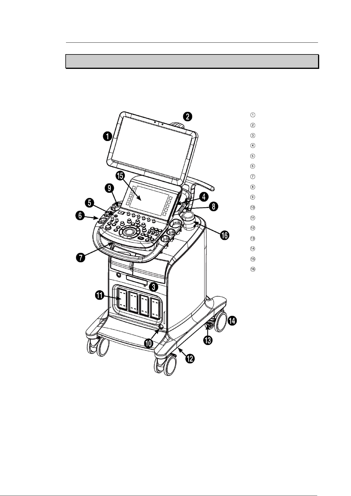
Chapter 2. Introduction 2 - 5
[Figure 2.1 Front of the HS70A]
Monitor
Monitor arm
DVD drive
Speaker
Control panel
Probe holder
Keyboard
Lift
USB port
CW probe port
Probe port
Air filter
Brake
Wheels
Touch panel
Gel Warmer (Option)
Product Configuration
This product consists of the monitor, the control panel, the console, the peripheral devices, and
the probes.
Page 59
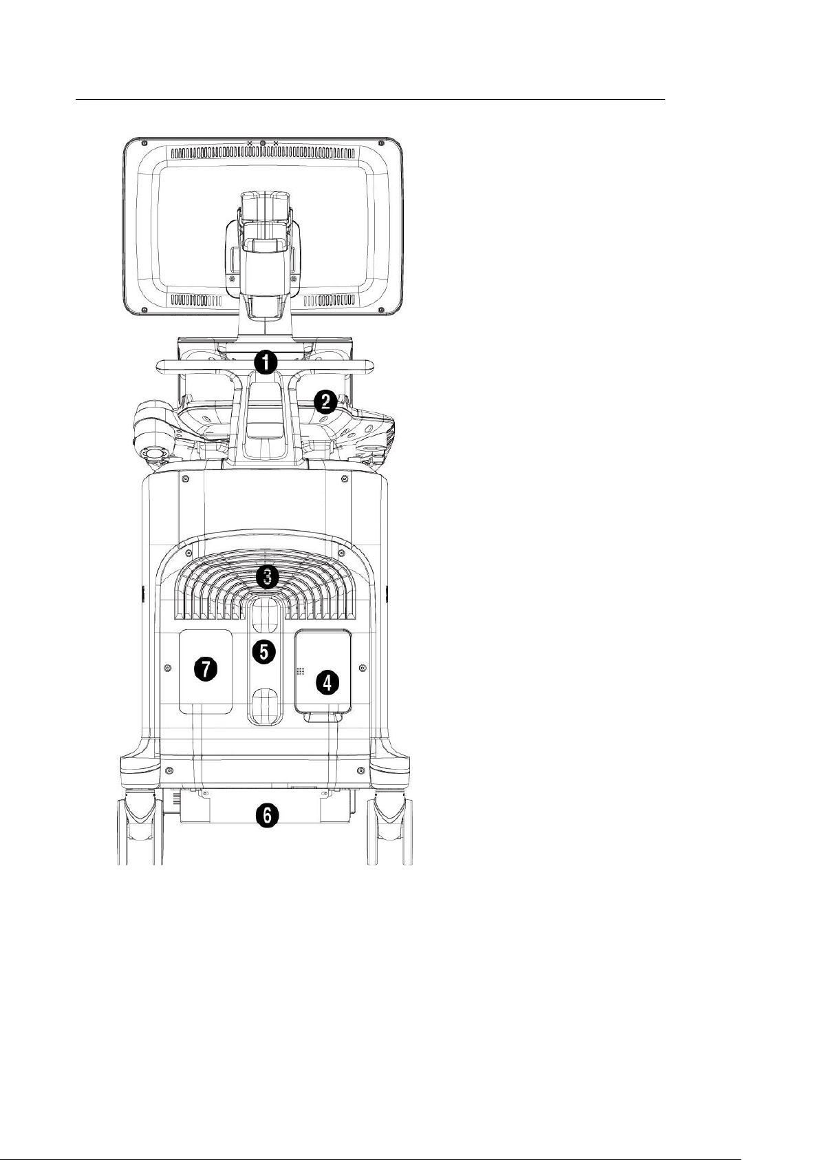
2 - 6 HS70A Service Manual
[Figure 2.2 Back of the HS70A]
① Handle
② Storage compartments
③ Ventilation
④ Rear panel
⑤ Cable holder
⑥ Power connection part
⑦ ID Label
Page 60
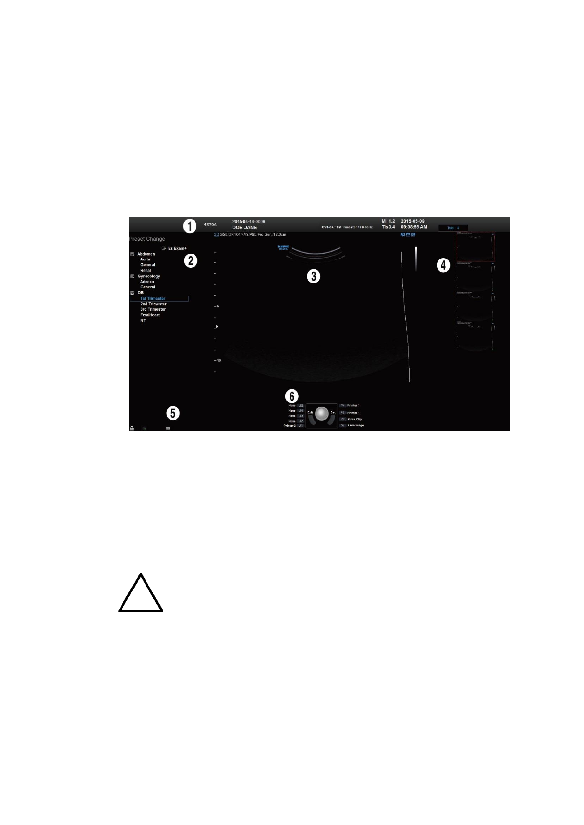
Chapter 2. Introduction 2 - 7
NOTE
The Ez Exam+ menu can be set up in Ez Exam+ Setup. For details about Ez
Exam+ Setup, please refer to ‘Chapter 3. Utilities’.
Monitor
Ultrasound images and other information are displayed on the color LCD monitor.
▌ Screen Layout
The monitor displays ultrasound images, operation menus and a variety of other information.
As shown in the image below, the screen consists of ① Title Area, ② Preset Change and
Ez Exam+ Area ③ Image Area, ④ Thumbnail Area, ⑤ User Information Area, and ⑥ User
Defined Key Area.
[Figure 2.3 Monitor Display]
① Title Area
Displays patient name, hospital name, application, frame rate and depth, probe
information, acoustic output information, and date and time.
② Preset Change and Ez Exam+ Area
Displays Preset Change. You can quickly change the preset of a probe. If you are using
Ez Exam+, the Ez Exam+ menu will be displayed.
Page 61

2 - 8 HS70A Service Manual
NOTE
For information on User Key Setup, please refer to ‘Chapter 3. Utilities’.
TIP
Principles of Operation of the Diagnostic Ultrasound System
Medical ultrasound images are created when the computer’s digital memory
converts the high-frequency wave signals that are transmitted and received by
the probe.
As ultrasound waves propagate through the human body, they generate
reflected signals whenever they encounter a change in density. For example,
reflected signals are generated when signals pass from fatty tissues to muscle
tissues. Reflected signals return to the probe where they are converted into
electronic signals. The reflected signals are amplified and processed by analog
and digital circuits that have filters for various frequencies and response time
options. Then they are again converted into high-frequency electronic signals,
and saved as a series of digital image signals. The monitor displays the image
signals stored on the storage device in real time.
The entire process of transmitting, receiving, and processing signals is
controlled by the computer.
③ Image Area
Displays ultrasound images, TGC, image information, annotation, and measurement
information are also displayed.
④ Thumbnail Area
Up to five saved images are displayed. (Save by pressing the Save button.) When you
save Single screens, up to 5 images are shown in a list; for Quad screens, up to 16
images are shown. Clicking with the pointer will enlarge the selected thumbnail in the
Image area. At the top of the Thumbnail area, you can see the total number of images
saved.
⑤ User Information Area
Information that is useful to the user, such as current system status, image information,
selectable items, etc., is displayed.
⑥ User Defined Key Area
Settings for User Defined Keys, including the positions of Set and Exit, are displayed.
You can change the setting of each button in Setup > User Defined Key.
Page 62
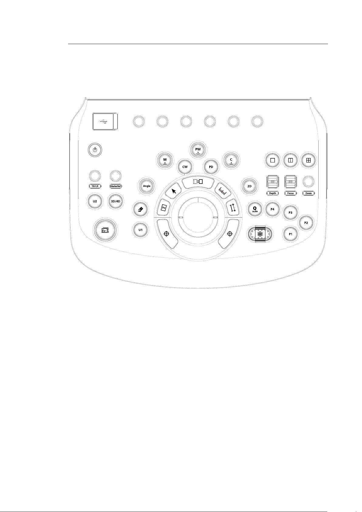
Control Panel
The system can be controlled by using the control panel.
Chapter 2. Introduction 2 - 9
[Figure 2.4 Control Panel]
The control panel consists of a keyboard, soft menus, buttons, dials, dial-buttons, a slider, and a
trackball.
The dial-button can be used both as a dial and a button.
Page 63
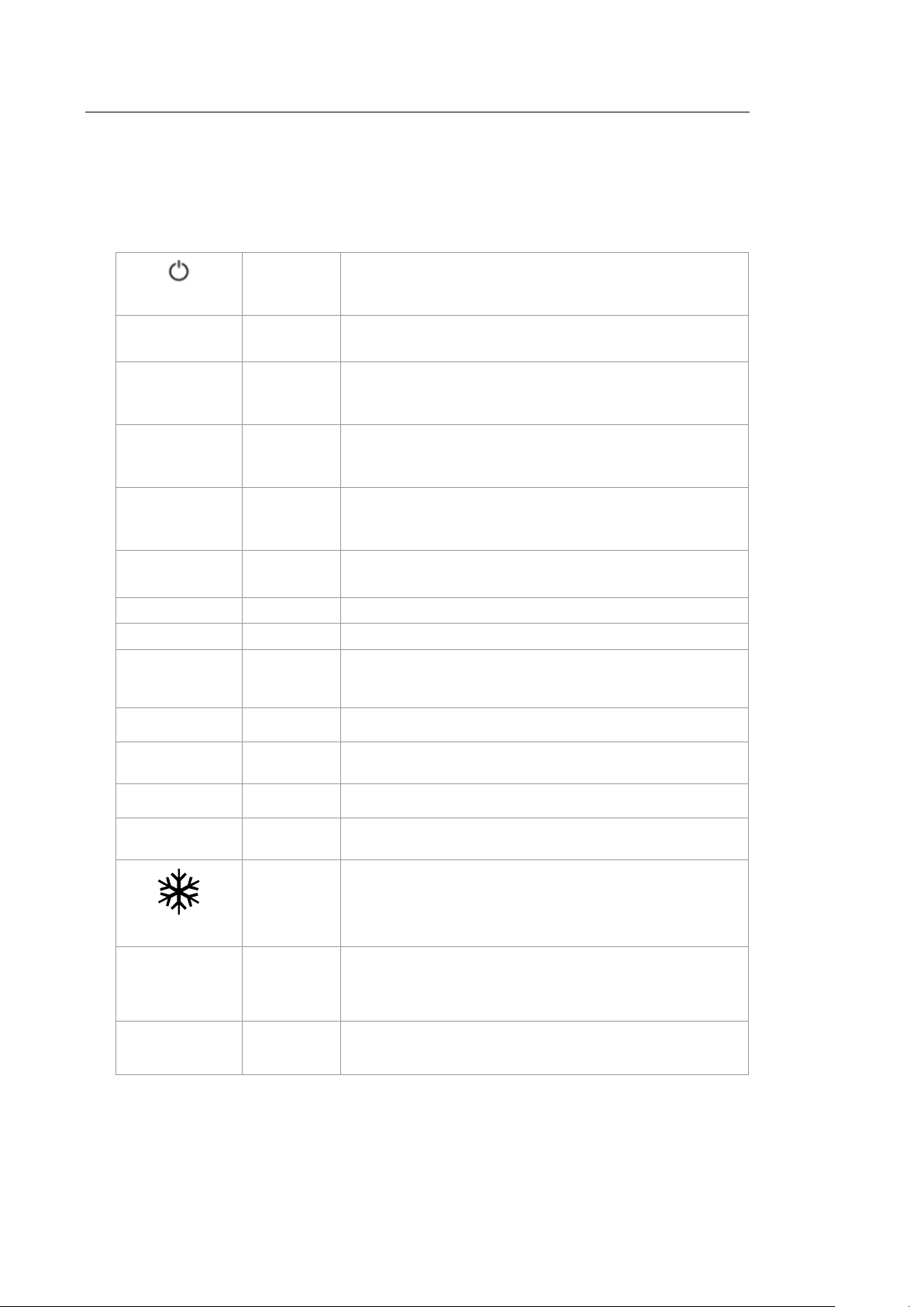
2 - 10 HS70A Service Manual
On/Off
Button
Turns the system on/off.
2D
Dial-button
– Button: Starts 2D mode.
– Dial: Adjusts the 2D gain.
M/x
Dial-button
– Button: Starts or ends M mode.
– Dial: Adjusts M gain. Also, turning this dial-button when in
3D View rotates the image along the x-axis.
PW/y
Dial-button
– Button: Starts or ends PW Spectral Doppler mode.
– Dial: Adjusts the PW gain. Also, turning this dial-button,
when in 3D View rotates the image along the y-axis.
C/z
Dial-button
– Button: Starts or ends Color Doppler mode.
– Dial: Adjusts the C gain. Also, turning this dial-button when
in 3D View rotates the image along the z-axis.
CW
Button
– Button: Starts or ends CW Spectral Doppler mode.
– Dial: Adjusts the CW gain.
PD
Button
Starts or ends Power Doppler mode.
3D/4D
Button
Starts or ends 3D/4D modes.
Angle
Dial-button
Adjusts the angle of the sample volume in Spectral Doppler
mode. It is also used to adjust the BodyMarker’s probe cursor
or indicator angle.
Depth
Switch
Adjusts the scanning depth of the image.
Focus
Switch
Changes location and number of focus on the target location
you wish to study.
Zoom
Dial-button
You can magnify an image.
Q Scan
Button
Press this button to turn the Quick Scan function on. The ‘Q
Scan’ mark will appear at the top of an image.
Freeze
Button
Pauses/resumes scanning.
P 1–4
Button
Stands for ‘Peripheral Key.’ This button allows users to select a
function to apply to the button. The function of each button can
be set in Setup > User Defined Key. The selected settings will
be displayed in the User Defined Key area of the monitor.
U 1–2
Button
Stands for ‘User Key.’ This button allows users to select a
function to apply to the button. The function of each button can
be set in Setup > User Defined Key. The selected settings will
▌ Functions of the Control Panel
The following are the descriptions and instructions for the controls on the control panel. For
more information on controls with multiple functions, see ‘Chapter 3. Utilities’ onwards in this
manual.
Page 64
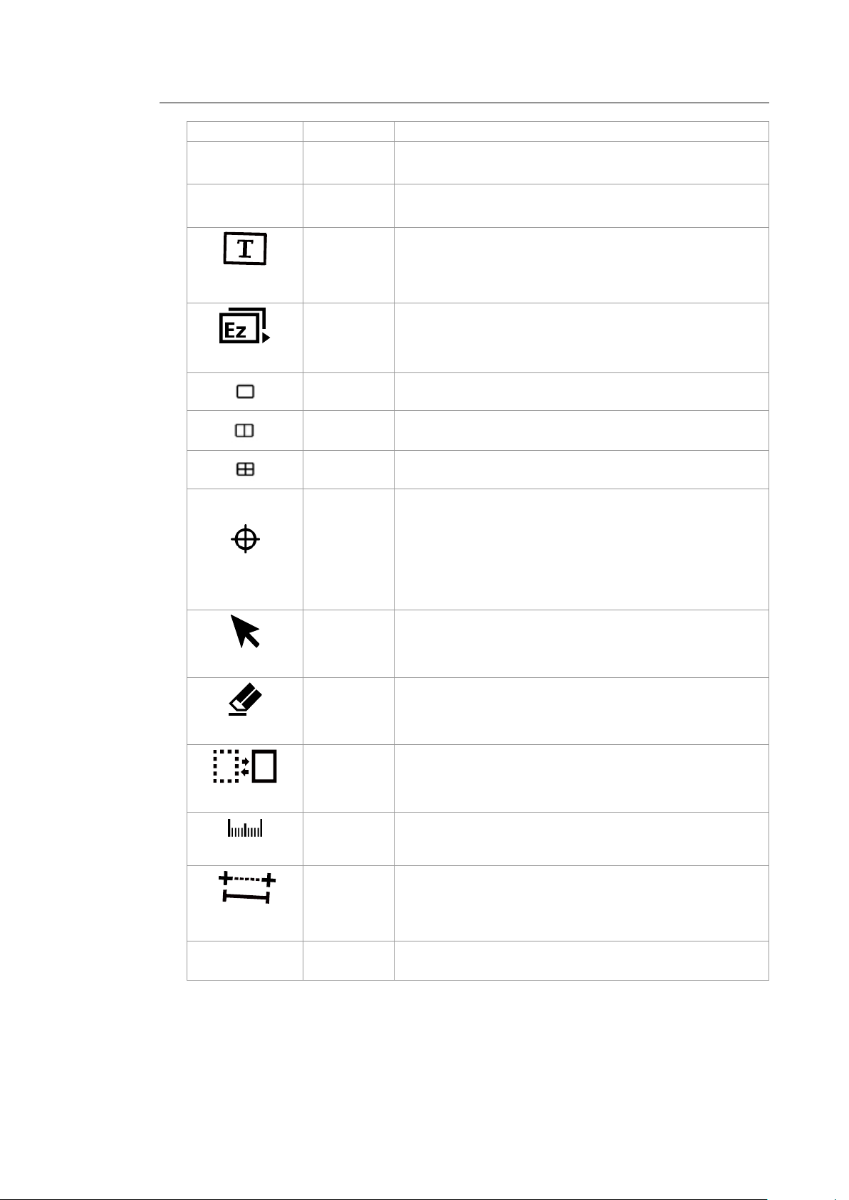
Chapter 2. Introduction 2 - 11
be displayed in the User Defined Key area of the monitor.
TB/LR
Dial-button
In 3D View-MPR, this dial-button adjusts ROI boundaries.
TB stands for Top-Bottom and LR stands for Left-Right.
Marker/Ref
Dial-button
Allows the user to enter a BodyMarker over an image.
Moves the reference slice horizontally in 3D View.
Text
Button
Allows the user to place text on an image.
Ez Exam+
Dial-button
Use the Ez Exam+ and Preset Change features.
Button
In this mode, only the image is displayed on the screen.
Button
Compares two independent images.
Button
Compares four independent images.
Set/Exit
Button
This button is used to assign user-defined functions. The
function of each button can be set in Utility > Setup > User
Defined Key.
– Set: Selects an item or value using the trackball or changes
the function of the trackball.
– Exit: Exits the function currently being used and returns to
the previous state.
Pointer
Button
When this is pressed, an arrow marker appears to point to
parts of the displayed image.
Clear
Button
Deletes text, indicator, BodyMarker, and measurement result,
etc. displayed on an image.
Change
Button
This is used to change the current trackball function.
Calculator
Button
Starts measurements by application.
Caliper
Button
Starts to measure distance, circumference, area, and volume.
Trackball
Trackball
Moves the cursor on the screen and scrolls through Cine
images.
Page 65
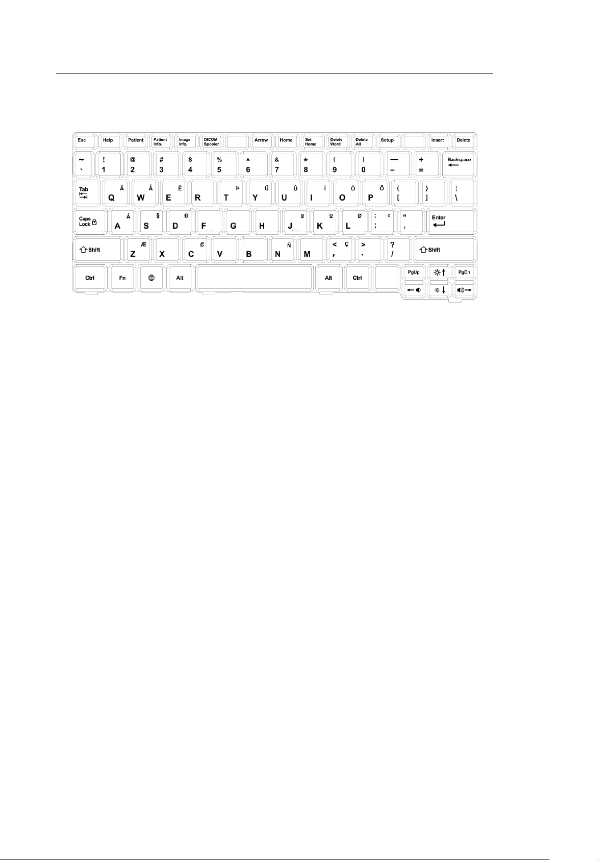
2 - 12 HS70A Service Manual
■ Keyboard
The keyboard is used to type in text.
[Figure 2.5 Keyboard]
Page 66
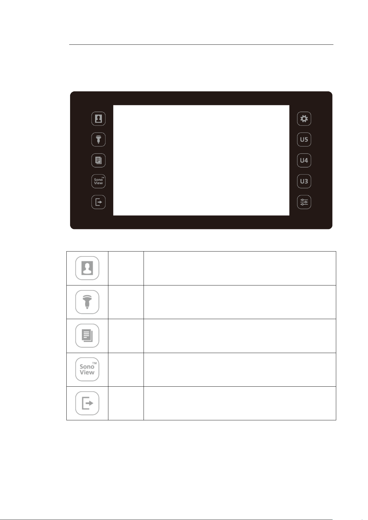
Chapter 2. Introduction 2 - 13
Patient
Displays the Patient Information screen, which is used for selecting a
patient ID from the list or entering new patient information.
Probe
Displays the Probe Selection screen to select or change the probe and
application.
Report
Displays the Report screen that shows the measurement results of the
current application and other information.
SonoView
Runs SonoView, which is the image filing program.
End Exam
Finishes the exam of the currently selected patient and resets the related
data.
▌ Touch Panel
These control tools are located on both sides of the touch screen. Available buttons are as
follows:
[Figure 2.6 Touch Panel]
Page 67
2 - 14 HS70A Service Manual
Utility
The Utility Menu appears on the touch screen.
U5
Stands for User Key; functions can be assigned to these buttons as
desired. The function of each button can be set in Setup > User Defined
Key. The settings are displayed in the User Defined Key area in the
monitor.
U4
Stands for User Key; functions can be assigned to these buttons as
desired. The function of each button can be set in Setup > User Defined
Key. The settings are displayed in the User Defined Key area in the
monitor.
U3
Stands for User Key; functions can be assigned to these buttons as
desired. The function of each button can be set in Setup > User Defined
Key. The settings are displayed in the User Defined Key area in the
monitor.
TGC
The TGC screen will be displayed on the touch screen. TGC stands for
Time Gain Compensation.
Page 68
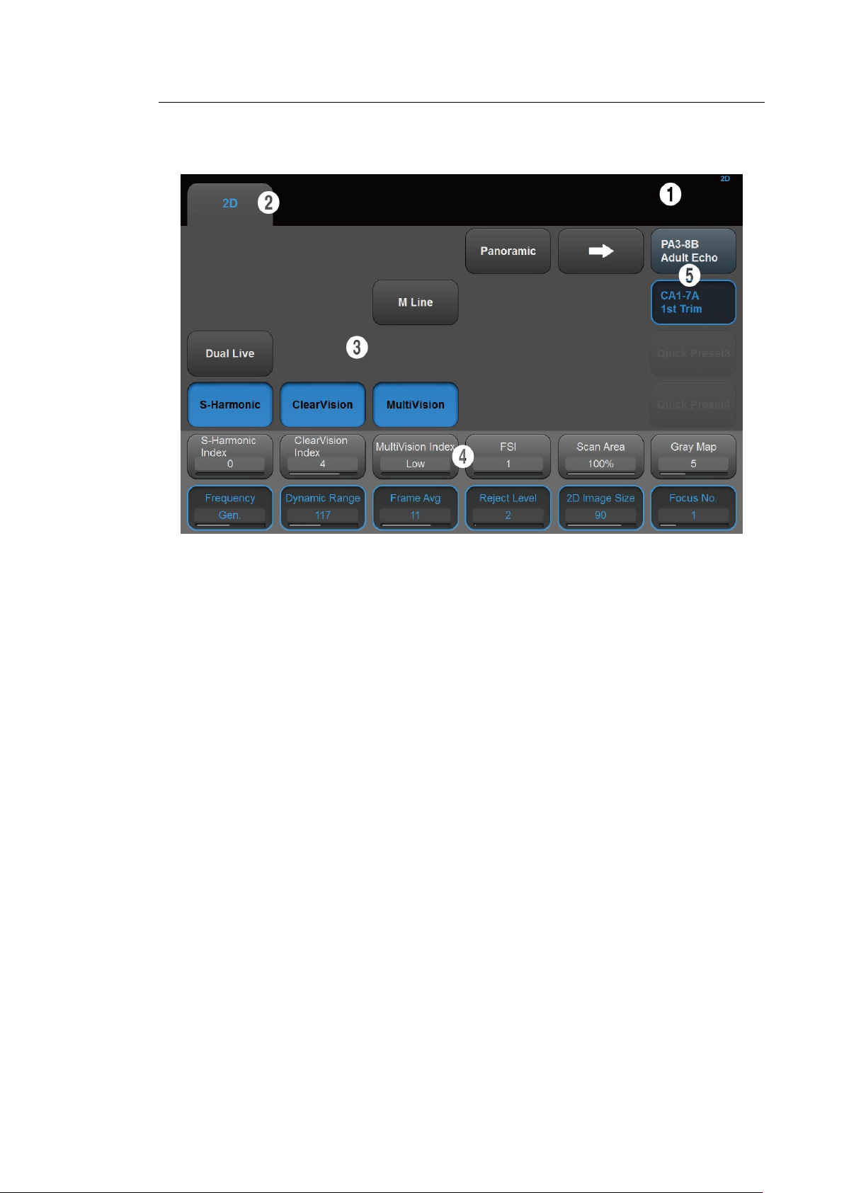
▌ Touch Screen
Chapter 2. Introduction 2 - 15
[Figure 2.7 Touch Screen]
The touch screen is an operating tool that can be touched by the user to input data. The
functions that are available in the current mode are shown in the form of buttons or a dialbutton.
■ Touch Screen Layout
① Information Area: Shows the title of the touch screen currently displayed.
② Tab Area: Shows diagnostic modes and utilities under different tabs. The touch screen
can be changed by pressing one of the tabs.
③ Menu Area: The menu items that are available in the current input mode are shown in
the form of buttons. The user can access the desired menu item by pressing the
corresponding button. The menu currently in use is shown in blue.
④ Soft Menu Area: The soft menu items that are available in the current input mode are
shown.The menus in use are shown with blue borders. Press or rotate the dialbuttons right below each menu.
⑤ Quick Preset: With predefined diagnosis mode and presets of probes frequently used
by the user, this function provides quick and easy access to frequently used probe in
each diagnosis mode.
Page 69

2 - 16 HS70A Service Manual
NOTE
For further details about setting up Quick Preset, please refer to Setup >
General > Quick Preset > Quick Preset Setup in ‘Chapter 3. Utilities’.
CAUTION
■ Do not apply excessive force to the control panel.
■ Use the handle at the back of the product when moving it.
▌ Adjusting the Control Panel
■ Adjusting to the Right and Left
Hold the control panel handle and move it carefully to the right or left.
■ Adjusting the Height
Press the lever on the control panel handle and move it carefully up or down.
Page 70
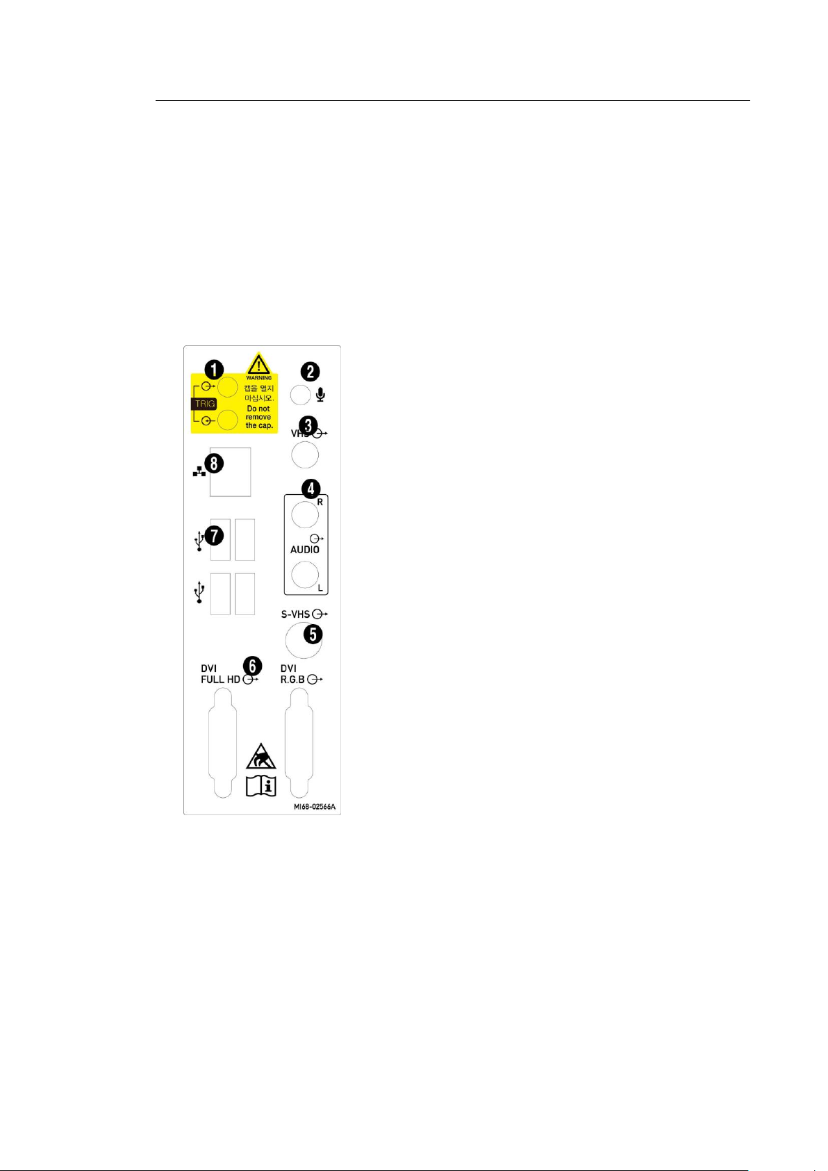
Chapter 2. Introduction 2 - 17
[Figure 2.8 Rear Panel]
① Trig port (In/Out): Not used.
② Microphone port (Input): Connects a microphone.
③ VHS port (Output): Outputs composite image to the
monitor.
④ Audio port (Output): Outputs audio signal.
⑤ S-VHS port (Output): Outputs S-VHS image to the
monitor.
⑥ DVI port (Output): Outputs digital signal (DVI Full
HD) and analog signal (DVI RGB) to the monitor.
⑦ USB port: Used to connect to USB peripheral
devices.
⑧ Network port: Used to connect to a network. You
can transfer patient information to another server
via the DICOM network.
Console
The console consists of two main parts: the interior and the exterior. The interior of the console
mainly contains devices that produce ultrasound images. On the exterior of the console are
various connectors, probe holders, storage compartments, handles, and wheels, etc.
▌ Rear Panel
A monitor and other peripheral devices are connected via the rear panel at the back of the
system.
Page 71
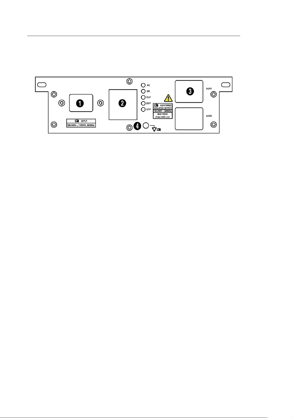
2 - 18 HS70A Service Manual
TIP
Vaginal Probe Holder
Install this to fix the vaginal probe onto the holder.
▌ Power Connection Part
The power connection part is located at the bottom on the rear panel.
[Figure 2.9 Power Connection Part]
① Power switch: Supplies or blocks power to the entire system.
② Power Inlet: For the power cable to connect to external power.
③ Power Outlet: Supplies an external peripheral device with power from the product’s
internal power supply.
④ Equipotential Terminal: This should be connected to the equipotential connection part in
the exam room.
▌ Probe Holders
Probe holders are mounted at the left and right-hand sides of the control panel.
Page 72
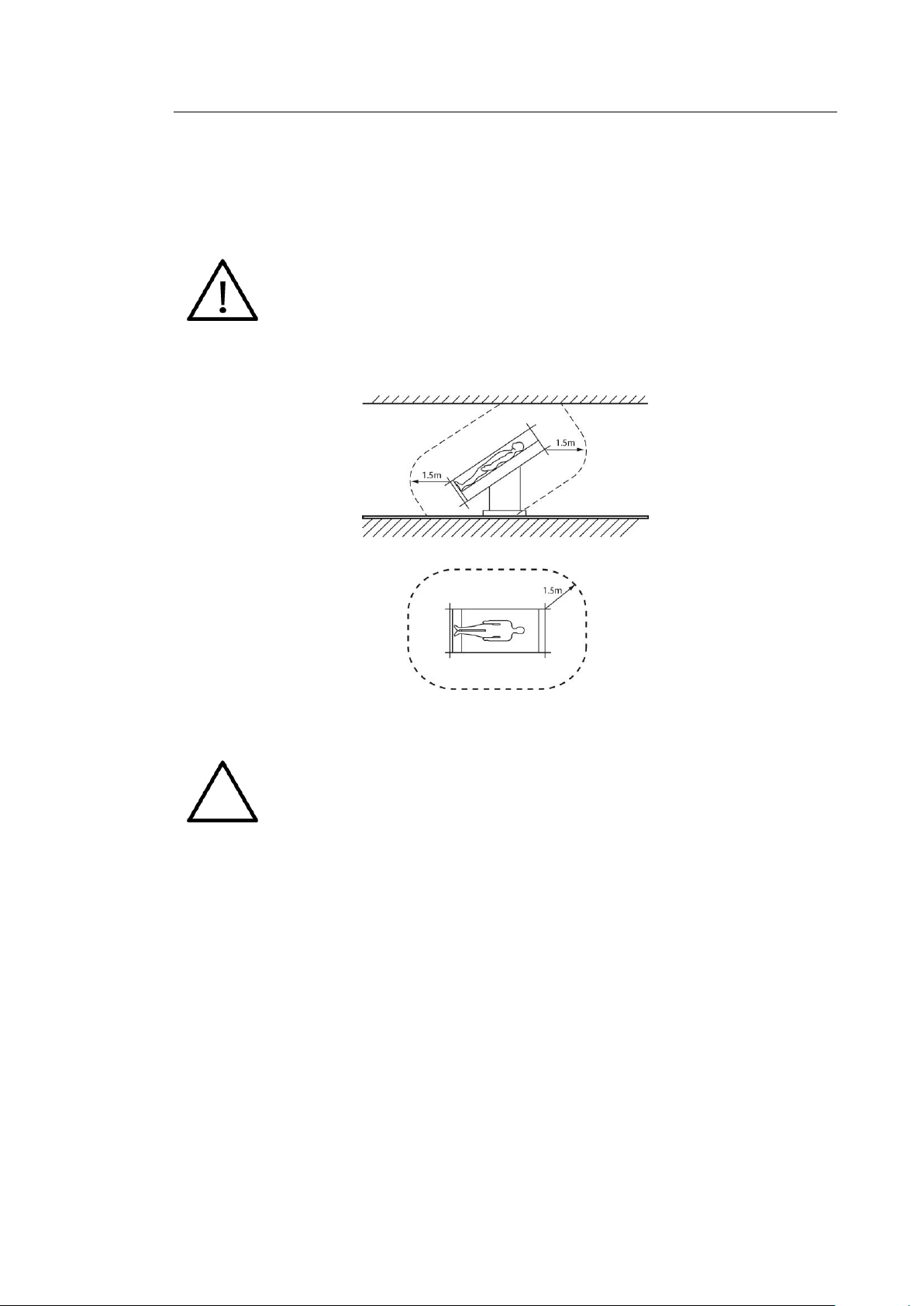
Chapter 2. Introduction 2 - 19
CAUTION
■ Do not install a peripheral device that is not listed in this user manual in the
patient environment. If you install an unlisted device in the patient
environment, it may cause an electrical hazard.
■ Do not connect additional external peripheral devices to the auxiliary socket
outlet. Doing so may decrease safety level.
NOTE
Refer to the user manual of the peripheral device for its operating information.
Peripheral Devices
Peripheral devices can be connected to their corresponding ports on the left/right or rear sides
of the console, as needed.
[Figure 2.10 Patient Environment]
▌ Internal Peripheral Devices
These are peripheral devices mounted in the system.
■ DVD-Multi
DVD-RW, DVD+RW, DVD-R, DVD+R, CD-R, CD-RW, CD-ROM
■ Hard Disc Drive
At least 500 GB
Page 73
2 - 20 HS70A Service Manual
CAUTION
When using a peripheral device via a USB port, always turn the power off before
connecting/disconnecting the device. Connection/disconnection of USB devices
during power-on may lead to malfunction of the system and the USB devices.
NOTE
■ When removing the removable disk, use Utility > Storage manager.
■ USB ports are located both on the control panel and the rear panel of the
console.
We recommend that you connect USB storage devices (flash memory media,
etc.) to the ports on the control panel, and other USB peripheral devices to
the rear panel for convenience.
CAUTION
■ You must install a printer and driver compatible with the English version of
Microsoft Windows 7. Contact Samsung Medison customer service
department for inquiries about printer driver installation.
■ When connecting the printer, ensure that the printer is configured under
Microsoft Windows or system setup and has been chosen as the default
printer.
■ Please check the port that the printer uses before connecting. Printers should
be connected to the printer port while the USB printer should be connected to
the USB port.
▌ External Peripheral Devices
These are peripheral devices that can be connected for use when needed and are
connected via the USB port located at the rear panel.
The following products are recommended:
■ USB Video Printer
– Black and White: Mitsubishi P95DE (Japan: Mitsubishi P95D), SONYUP-D897, SONY
UP-X898MD, SONY UP-D898MD
– Color: Mitsubishi CP-30DW, SONY UP-D25MD
■ USB Line Printer
– Black and White: Samsung ML-2955DW
– Color: Samsung CLP-615ND
■ USB to RS-232C Serial Cable
USB to Serial (RS-232C) Converter with FTDI Chipset (FTDI FT232BM Compatible)
Page 74

Chapter 2. Introduction 2 - 21
NOTE
For more information about the Open Line Transfer, refer to ‘Chapter 9.
Measurements and Calculations’.
NOTE
■ The system cannot recognize USB 1.1 flash memory. Remove the flash
memory from the console and equip again with an appropriate device.
■ Regarding file formats that are not ordinarily saved: Please check first to see
if it is possible to save the file format on a desktop PC before trying to save
the file on flash memory.
■ Do not use flash memory media which contain anti-virus programs or are
defective. Otherwise, the product may fail to work properly.
■ Foot Switch
– 3 Pedals HID Type
To configure the foot switch function, go to Utility > Setup > Peripherals > Foot Switch.
You can select one function from the following: Freeze, Update, Record, Print1, Save,
Store Clip, Volume Start, Ez Exam, PD Mode, Color Mode, M Mode, PW Mode, CW
Mode, ElastoScan, TDI Mode, TDW Mode, or Biopsy.
■ Misc.
Flash Memory Media
Page 75
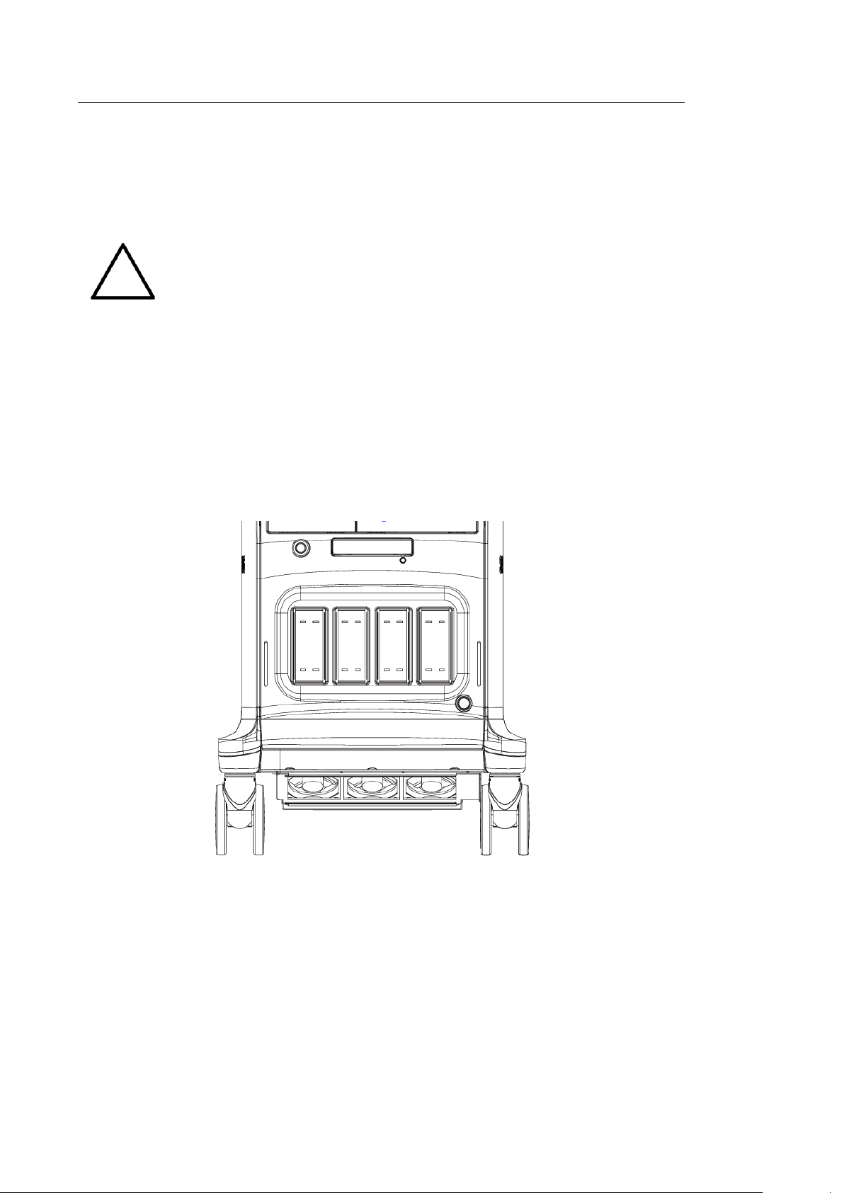
2 - 22 HS70A Service Manual
NOTE
For more information on probes, refer to ‘Chapter 5. Probes’ and the ‘Reference
Manual’.
Probes
Probes are devices that generate ultrasound waves and process reflected wave data for the
purpose of image formation.
▌ Connecting probes
To ensure the safety of the product and the probe, turn off the power before connecting the
probe to, or disconnecting it from, the probe port.
1. Connect probes to the probe ports on the front panel of the system. A maximum of five
probes including the CW probe can be connected at one time. The CW probe should CW
only be connected to its own port.
2. To install, turn the connector turning handle clockwise.
[Figure 2.11 Probe Ports]
Page 76
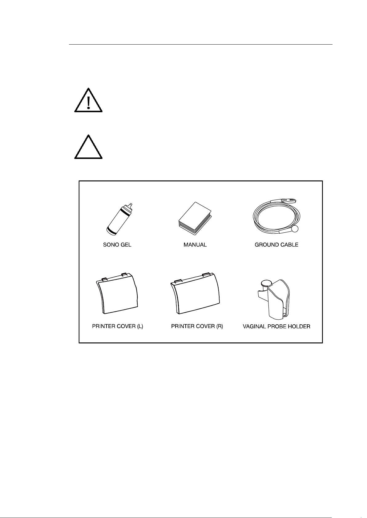
Chapter 2. Introduction 2 - 23
CAUTION
Main cord set, separately certified according to the relevant standards, is to be
used when supplied to EU and USA/CAN.
NOTE
Accessories can be different according to the country.
Accessories
An accessory box containing the items below is supplied with the product.
[Figure 2.12 Accessories]
Page 77

2 - 24 HS70A Service Manual
■ SMART 4D
■ CW Function
■ Cardiac Measurement
■ DICOM
■ XI STIC
■ ElastoScan
■ Panoramic
■ Stress Echo
■ Strain+
■ ADVR
■ E-Thyroid
■ Realistic Vue
■ AutoIMT+
■ E-Breast
■ 2D NT
■ Mobile Export
■ 5D Follicle
■ 5D NT
■ 5D LB
■ 5D CNS
■ HDVI
■ S-Shearwave
■ Arterial Analysis
■ DICOM Q/R
■ CEUS+
■ S-Detect for Breast
■ S-Detect for Thyroid
Optional Functions
This product has the following S/W optional functions:
For further information about optional functions, please refer to the relevant chapters in the
HS70A User manual.
Page 78

Chapter 3
Chapter 3 Installing the Product
Installing the Product
Transporting ................................................................................................................. 2
Unpacking the Product ................................................................................................. 3
Installation Environment ............................................................................................... 4
Installing the Product .................................................................................................... 5
Connecting Peripherals .............................................................................................................. 7
System Power .............................................................................................................. 9
Turning the Power On ................................................................................................................ 9
Shutting Down the System ....................................................................................................... 10
Preset ................................................................................................ ......................... 11
General .................................................................................................................................... 12
Scan Mode ............................................................................................................................... 17
Display ..................................................................................................................................... 20
Annotate ................................................................................................................................... 24
Peripheral Device Settings ....................................................................................................... 29
User Defined Keys ................................................................................................................... 33
Network .................................................................................................................................... 35
DICOM Setup (Optional) .......................................................................................................... 37
Options ..................................................................................................................................... 49
System Information .................................................................................................................. 51
Page 79
3 - 2 HS70A Service Manual
Category
Temperature OC
Humidity %
Transporting
-25 ~ 60
20 ~ 90
Storage
-10 ~ 50
20 ~ 90
Operating
10 ~ 35
30 ~ 75
Transporting
This product is a finely tuned piece of medical electronic equipment; careful attention is required
when transporting it.
▐Precautions when transporting the product
The box packaging is designed to reduce impact. However, take care to prevent any external
impact from reaching the product.
▐Humidity and Temperature
"[Table 3-1. The Product's Humidity and Temperature Tolerance]" shown below illustrates the
temperature and humidity ranges for transporting, storing, and operating the product.
[Table 3-1. The Product’s Humidity and Temperature Tolerance]
Page 80
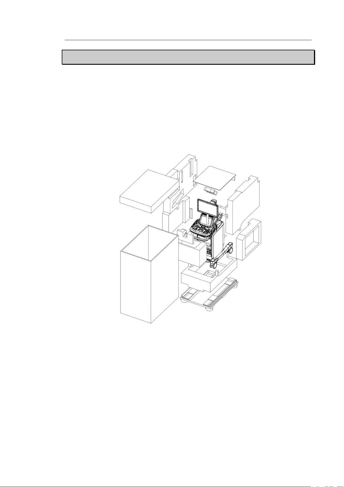
Chapter 3. Installing the Product 3 - 3
Unpacking the Product
Dismantling the Product Box
1. Open the box.
2. Remove the protection cover.
3. Take out the probe box and accessory box and store them in a safe place.
4. Unlock the brakes on wheels.
5. Grab the rear handle on the product and move it to a place to install.
[Figure 3.1 Dismantling the Product Box]
Accessory
An accessory box containing the items below is supplied with the product. If the items are not
intended for your product, contact the store where you purchased the product.
Page 81

3 - 4 HS70A Service Manual
CAUTION
Placing the system near generators, X-ray machines or broadcast cables
may result in screen noise and abnormal visual images. Sharing the
power source with other electrical devices may also induce noise.
Installation Environment
Caution
When installing the product, please pay attention to the following: For more information on using
and setting up, refer to the accompanying manual for HS70A.
■ Optimal conditions for the system are a temperature of 10-35 and a humidity of 30-75%.
■ Avoid excess humidity.
■ Avoid direct sunlight.
■ Avoid excessive fluctuations in temperature.
■ Maintain temperature of 10 - 35 and humidity of 30 - 75% for normal operation.
■ Avoid installing the product near a heating appliance.
■ Avoid dusty and/or poorly ventilated locations.
■ Avoid locations that are subject to vibration.
■ Avoid locations where chemical substances or harmful gases are present.
Page 82
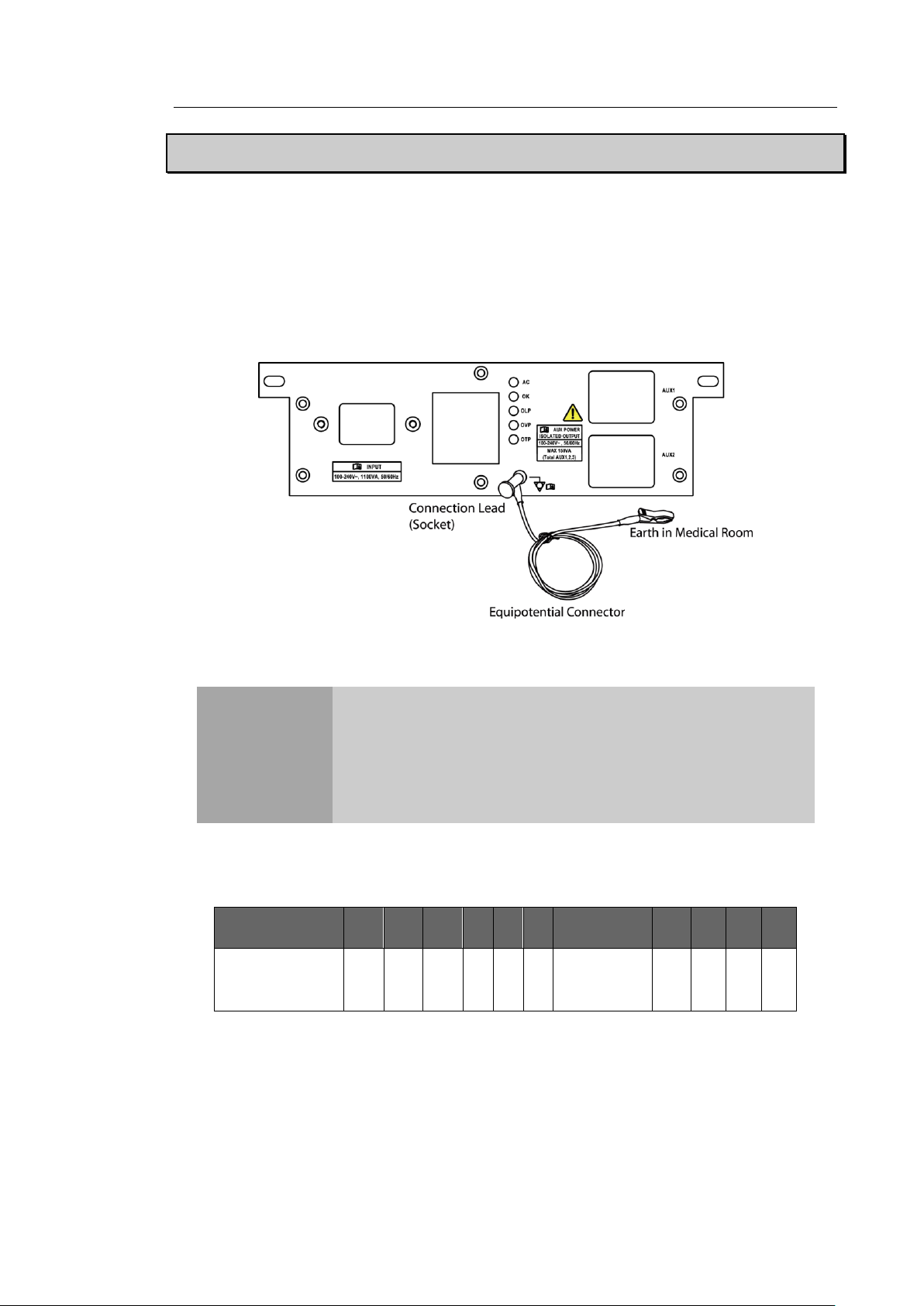
Chapter 3. Installing the Product 3 - 5
CAUTION
If the product needs to be transported or stored for an
extended duration, the temperature and humidity of the
environment must be checked.
A sudden change in temperature may cause condensation and
lead to product failure.
Temperature℃
-20
-15
-10
-5 0 5
10 ~ 35
45
50
55
60
Waiting time
Hour
16
10 8 6 4 2
Use
immediately
2 4 6
10
Installing the Product
Installation Safety
In a hospital environment, dangerous electric current may occur as a result of the potential
difference between a contactable conductive part and connected equipment in treatment rooms.
The solution to the problem is consistent equipotential bonding. Medical equipment is connected
with connecting leads made up of sockets which are angled to the equipotential bonding network
in medical rooms.
[Figure 3. 2 Equipotential bonding]
Refer to "[Table 3-2. Operational Temperature of Product]" before turning the product on.
[Table 3-2. Operational Temperature of Product]
Page 83
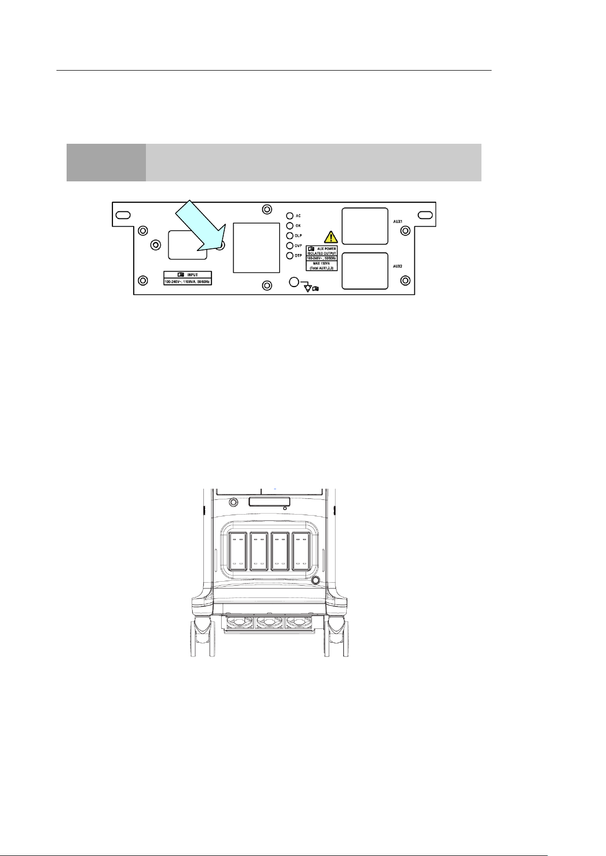
3 - 6 HS70A Service Manual
NOTE
The product may ship with the power cable connected to the console.
Power Cord Connection
Prior to connecting a power cord, verify that the voltage indicated on the power cord matches the
voltage rating of the place to install.
[Figure 3.3 Power Connection Part]
Probe Connection
Be sure to turn off the power before connecting or disconnecting a probe to ensure the safety of
the system and the probes.
1. Connect probes to the probe connectors on the front panel of the system. A maximum
of five probes including the CW probe can be connected at one time. The CW probe
should only be connected to its own connector.
2. To install, turn the connector turning handle clockwise.
[Figure 3.4 Connecting the Probe]
Page 84
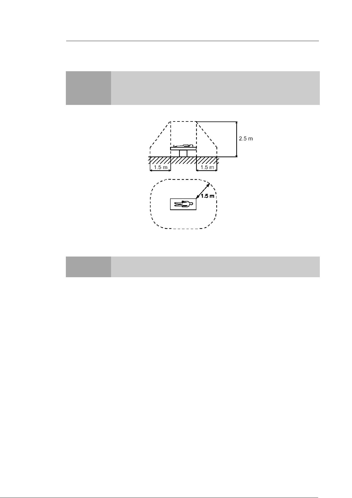
Connecting Peripherals
CAUTION
Do not place peripheral devices that are not listed in this manual in the vicinity
of the patient. If you place them in the patient environment, it may cause an
electrical hazard.
NOTE
For more information on the recommended peripheral devices, refer to
"Chapter 1. Introduction".
Chapter 3. Installing the Product 3 - 7
[Figure 3.5 Patient Environment]
▐Internal Peripheral Devices
These are peripheral devices mounted in the system.
DVD-Multi
Hard Disc Drive
Page 85

3 - 8 HS70A Service Manual
NOTE
When removing the removable disk, use Utility > Storage manager.
The system cannot recognize USB 1.1 flash memory. Remove the flash
memory from the console and equip again with an appropriate device.
CAUTION
When using a peripheral device via a USB port, always turn the power
off before connecting/disconnecting the device.
Connection/disconnection of USB devices during power-on may lead to
malfunction of the system and the USB devices.
Do not connect additional external peripheral devices to the auxiliary
socket outlet. Doing so may decrease safety level.
▐External Peripheral Devices
These are peripheral devices that can be connected for use when needed and are connected
via the USB port located at the rear panel.
USB Video Printer
USB Line Printer
USB to RS-232C Serial Cable
Foot Switch
Other Flash Memory Media
Page 86

Chapter 3. Installing the Product 3 - 9
NOTE
If the power switch near the power connection port on the rear panel
of the product has been switched off, wait for 10 seconds before
turning on the product.
Do not press keyboard keys or buttons while booting is in progress.
Doing so may cause the system to malfunction.
If you turn on the power after turning it off suddenly, the system may
turn on and off momentarily. This is a characteristic of the Intel® PC
main board, and not a system error.
CAUTION
Make sure to connect the probes and peripheral devices that will be used
before powering on the system. If you attempt to connect them during
system use, it may lead to patient injury or irreparable damage to the
console.
CAUTION
Before starting the diagnosis, you must register the patient information.
System Power
Boot up the system for use.
Turning the Power On
Press the On/Off button when the power is off. Booting begins, and the product logo appears on
the screen. When booting is completed, the 2D mode screen appears in End Exam status.
Page 87

3 - 10 HS70A Service Manual
CAUTION
Pressing the On/Off button for longer than five seconds will
immediately turn the power off and may damage the hard disk; do
not turn off the power by using this method unless absolutely
necessary.
To ensure that the product is safely cut off from electrical power, set
the power switch at the rear of the product to Off position after using
the product.
Shutting Down the System
Press the On/Off button while using the system to initiate shutdown.
Page 88
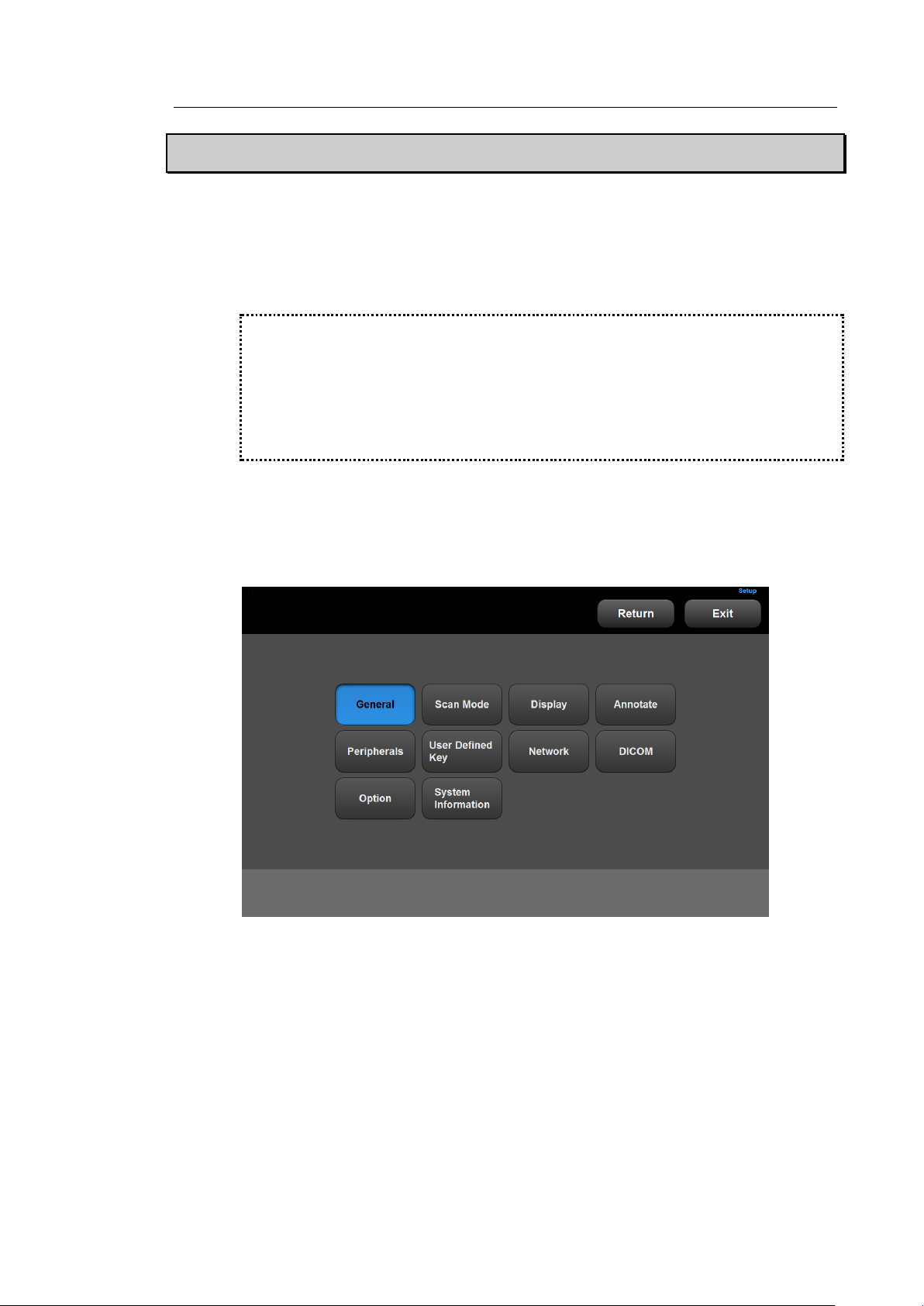
Chapter 3. Installing the Product 3 - 11
※ Tip! – Selecting a tab
You can select a desired tab in either one of two ways. Select the method that suits
you.
- Use the trackball and the Set button to select a tab.
- Tap a corresponding button on the touch screen.
Preset
This mode is used for system settings. It does not affect image output. The setup may be
modified depending on specific needs or preferences.
1. Press the Setup button on the touch panel, or tap Utility > Setup on the touch screen.
2. The Settings screen will appear. Select a tab that has items to specify.
3. Specify settings for each item.
4. Save and close the settings. Click the Close button on the monitor screen or the Exit
button on the touch screen or the control panel to switch to Scan Mode.
5. Tap Return on the touch screen to go back to the Utility menu.
[Figure 3.6 Setup - Touch Screen]
Page 89
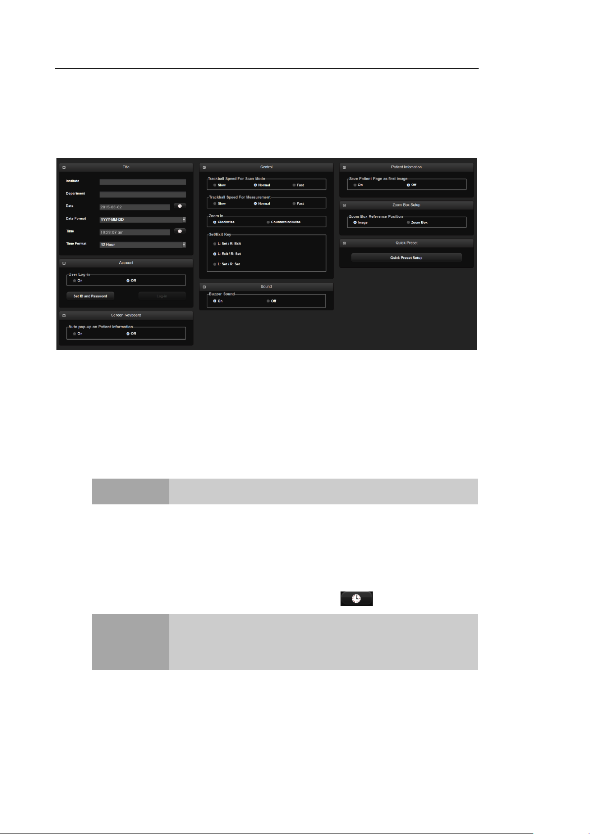
3 - 12 HS70A Service Manual
NOTE
You cannot input the following characters: #, [, ", :, ?, |, \, "
NOTE
You cannot change the date and time when a patient ID has been
registered. Before making a change, you should finish the current
diagnosis by pressing the End Exam button on the control panel.
You can select a year from 2006 to 2027.
General
In the Setup screen, select the General tab. Or tap General on the touch screen. You can
specify general settings such as title settings.
[Figure 3.7 Setup - General]
▐ Title
You can specify the information that is displayed in the title area on the screen.
Institution
Enter the name of the hospital/institution where the product is installed.
Department
Enter details about the medical institution or the organization. These details are used to
identify information at DICOM transfer.
Date
The current date is displayed. To change the date, press .
Page 90
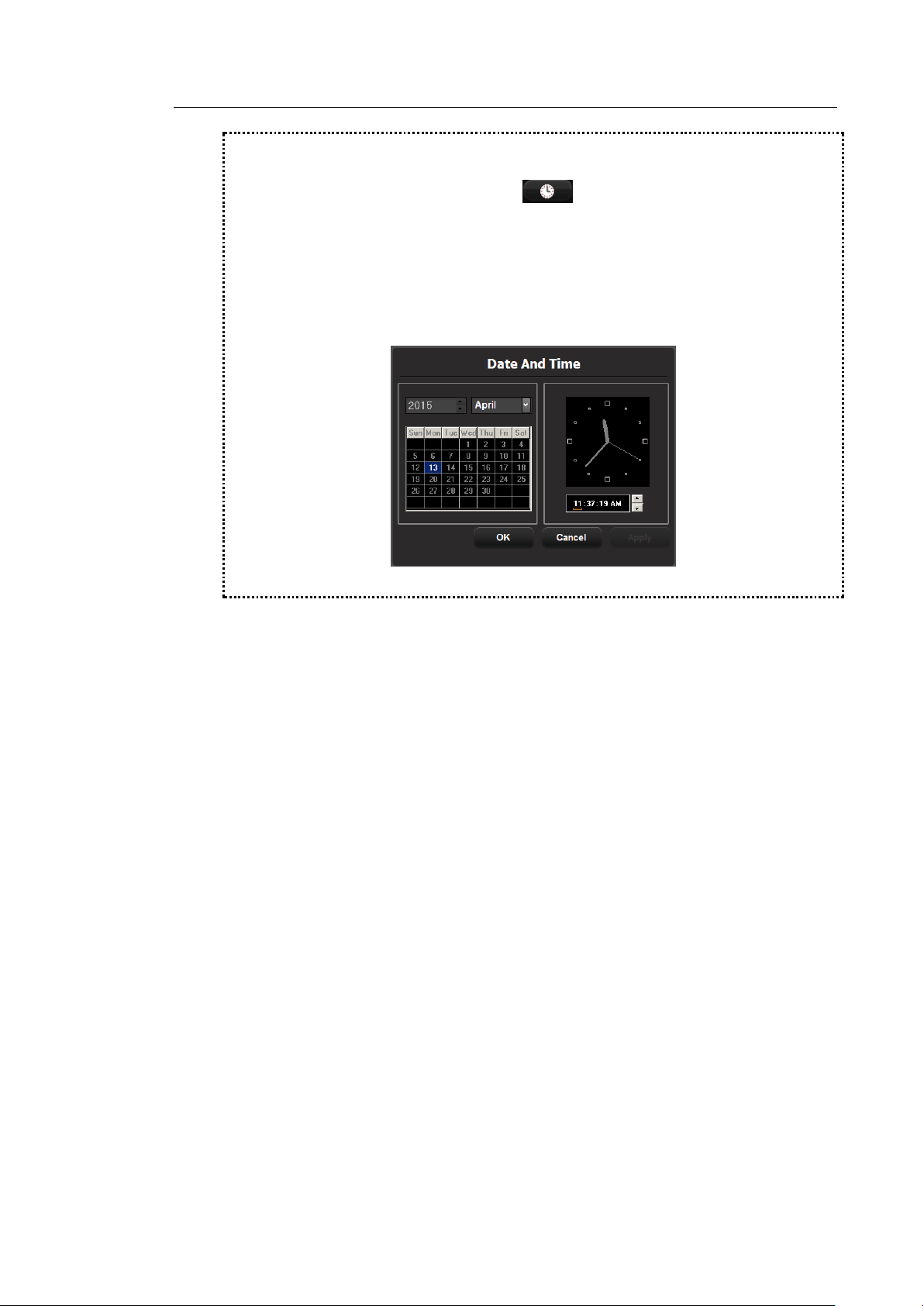
Chapter 3. Installing the Product 3 - 13
※Tip! How to set the date and time
1. In the Date (or Time) field, press .
2. Set the date and time using the trackball and the Set button on the control
panel.
3. When the details are correct, press Apply to apply the changes. To close the
Date & Time window, press OK. To cancel, press Cancel or the Exit button on
the control panel.
[Figure 3.8 Date And Time]
Date Format
Used to configure the date format. Select a format by using the combo button. The date
format that you specify will be applied to various date fields in Patient Information.
Time
The current time is displayed.
Time Format
Select a time display format. Select a desired time format (12 Hour or 24 Hour) by
pressing the combo button.
▐ Account
Register a user ID and password.
User Log-in
Set the user account (log-in) function. If the user log-in is set to on, it can be used for the
following areas:
– Screen Saver
Page 91

3 - 14 HS70A Service Manual
NOTE
The Admin account cannot be deleted.
Once the user account function is activated, you cannot load
other exams without logging in.
The password must be 6 to 15 characters and composed of at
least three of the following:
- English alphabet upper case
- English alphabet lower case
- Numbers
- Special characters
– Accessing SonoView/Patient
– Search window for patient
Set ID and Password
This is the exclusive administrator function for approval and management of accounts.
Account List window will be enabled.
– Add: Fill out the User ID, Password, and Name fields. Then click the Add button to
create a new ID.
– Modify: Save the changes.
– Delete: Delete the selected ID.
– Close: Close the settings.
Log-in
You can set the User Account ID after logging in to the Admin account. For Admin
account, contact a service engineer.
▐ Screen keyboard
Auto pop-up on patient Information
Set this to on or off by using the trackball. If it is set to on, the on-screen keyboard
appears automatically when entering patient information.
▐ Control
Trackball Speed For Scan Mode
Specify the trackball speed at scanning mode as Slow, Normal, or Fast.
Trackball Speed For Measurement
Specify the trackball speed at measurement as Slow, Normal, or Fast. Slower
speeds allow more precise measurements.
Page 92

Chapter 3. Installing the Product 3 - 15
Zoom In
Selects the direction in which to rotate the Zoom dial to zoom in on an image.
- Clockwise: Rotating the dial-button clockwise zooms in on an image.
- Counterclockwise: Rotating the dial-button counter-clockwise zooms in on an image.
Set / Exit Key
Select the functions to assign to the buttons on the left and right sides of the trackball on
the control panel.
- L: Set / R: Exit: The left button is set to Set and the right button is set to Exit.
- L: Exit / R: Set: The left button is set to Exit and the right button is set to Set.
- L: Set / R: Set: Both the left and the right buttons are assigned the Set function.
▐ Sound
Generate a buzzer sound when a button or dial-button is used.
Buzzer Sound
Set this to on or off by using the trackball. When this is set to on, the buzzer sounds
each time a button or dial-button is used.
▐ Patient Information
Save patient Page as first images
Set this to on or off by using the trackball. If it is On, the Patient Information Entry screen
will be saved when creating an ID.
▐ Zoom Box Setup
Zoom Box Reference Position
Select the position of the Zoom Box Reference. You may select either Image or Zoom
Box.
Page 93

3 - 16 HS70A Service Manual
▐ Quick Preset
Quick Preset seutp
Press the button to display the Quick Preset Setup screen. After selecting the Probe,
Application, and Preset connected to the port, press the + button to add them to Quick
Preset. Up to 4 sets can be saved. The Probe, Application, and Preset saved will be
shown on the touch screen in the diagnosis mode.
Page 94
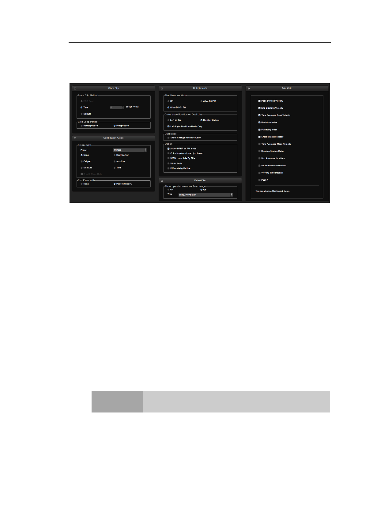
Chapter 3. Installing the Product 3 - 17
NOTE
To configure the Store Clip button, go to Utility > Setup > User
Defined Key > User Key Setup.
Scan Mode
Select the Scan Mode tab on the Setup screen. Or tap Scan Mode on the touch screen.
[Figure 3.9 Setup – Scan Mode]
▐ Store Clip
Store Clip Method
Specify the method and range in which an image is acquired and saved.
You can select ECG Beat, Time or Manual. Note that ECG Beat can be selected only
when ECG is on.
- ECG Beat: Specify the heart beat as 1–8 beats.
- Time: Specify it as 1–600 seconds.
- Manual: Pressing the button on the control panel that has been designated as Store
Clip automatically starts saving the images; pressing the same button again stops
saving.
Cine Loop Period
- Retrospective: When the Store Clip button is pressed during scanning, the previous
images are saved.
- Prospective: When the Store Clip button is pressed during scanning, the subsequent
images are saved.
Page 95

3 - 18 HS70A Service Manual
▐ Combination Action
Freeze with
Select a function to execute when the Freeze button on the control panel is pressed.
Available options are BodyMarker, Caliper, AutoCalc, Measure, Text, and None.
- D or M modes only: When 'Freeze with' is set to Measure, Measure Freeze Action
will function only in Doppler and M Modes.
End Exam with
- None: Tapping the End Exam button on the touch screen exits Exam Mode and
switches the screen to the B Mode Scan screen.
- Patient Window: Tapping the End Exam button on the touch screen switches the
screen to the Patient Information screen.
▐ Multiple Mode
Simultaneous Mode
You can decide whether to enable Simultaneous Mode in Spectral Doppler Mode, using
the following three options:
- Off: Select this if you do not wish to use Simultaneous Mode.
- Allow B / PW: Select this option if you do not wish to use Simultaneous Mode in
2D/C/PW Modes, but do wish to use it in 2D/PW Mode
- Allow B / C / PW: Select this if you wish to use simultaneous mode for both 2D/PW
and for 2D/C/PW.
Color Mode Position on Dual Live
Select the position of the Color Doppler Mode in Dual Live Mode.
- Left or Top: Color Doppler Mode is located in the left or upper part of the screen.
- Right or Bottom: Color Doppler Mode is located in the right or lower part of the
screen.
- Left-Right Dual Live Mode Only: The Top-Bottom Dual button disappears when
you check this checkbox.
Dual Mode
- Show ‘Change Window’ button: Select whether to activate the Change window in
Dual Mode.
Page 96

Chapter 3. Installing the Product 3 - 19
NOTE
The specified items will appear on the screen only when the AutoCalc button
on the touch screen is tapped in Spectral Doppler Mode.
Option
You can select multiple items. Use the trackball and the Set button to select and check
or uncheck an item.
- Active HPRF on PW mode: Select whether to activate HPRF (High Pulse Repetition
Frequency), which is supported in PW Spectral Doppler Mode. Check the checkbox
to use the HPRF function.
- Color Map Auto invert(on linear): Check this checkbox to automatically highlight the
Color Map. This is only applied when you change Steer in 2D/C/D Mode, C Mode,
or DPDI Mode in PD Mode.
- M/PW Loop Side by Side: Add Loop Side By Side display in M Mode or Power Spectral
Doppler Mode.
- Width Scale: Automatically fit the image size to the screen size when the depth of a
2D image is adjusted. Please note that this can be only used with linear probes.
- PW mode by M-Line: In 2D Mode, pressing the Set button when M Line is "on" will
take you directly to PW Mode.
▐ Default Text
Show operator name on Scan Image
- Type: Select Diag. Physician, Ref. Physician, or Sonographer. Turn this option off
to hide it from the screen.
▐ Auto Calc.
AutoCalc is a Spectral Doppler Mode feature that automatically performs specific calculations
based on measured values.
Add and remove automatic calculations by using the check boxes. You can select up to six
values.
When the Peak Systolic Velocity and End Diastolic Velocity values are 0, not all results for the
items will be displayed on the screen. In addition, the result value for Time Averaged Mean
Velocity is displayed only when Mean Trace is turned on.
Page 97
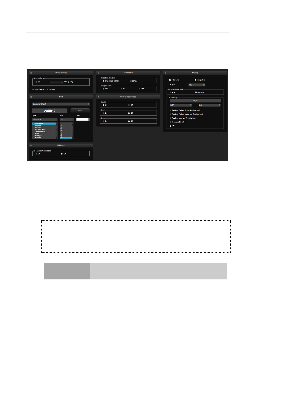
3 - 20 HS70A Service Manual
※Tip!
The Scan Mode is frozen automatically, regardless of Auto Freeze setting, when the
product is not used for 1 hour.
NOTE
In 3D mode, Auto Freeze is activated when the product is not
used for 20 minutes.
Display
Select the Display tab in the Setup screen. Or tap Display on the touch screen. Configure the
settings for displaying images.
▐ Power Saving
Screen Saver: Select whether or not to display the screen saver. When this is On,
you can set the screensaver to be activated in 1 to 30 minutes.
Auto Freeze in 10 minutes: Scan mode is frozen automatically when the product is
not used for 10 minutes.
[Figure 3.10 Setup - Display]
Page 98
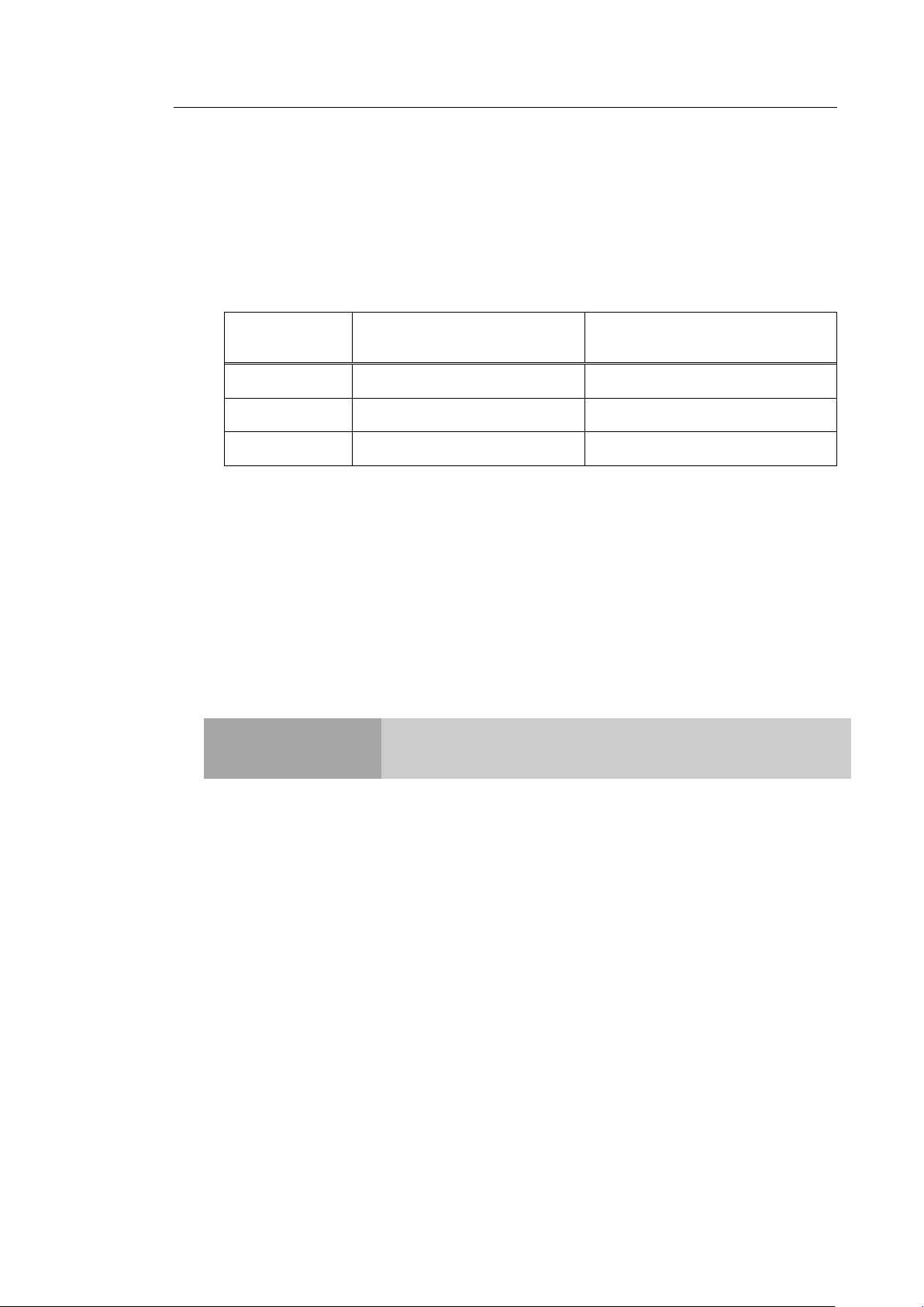
▐ Font
Document Font
Measure Result Font
Font Name
Helvetica
Verdana
Font Size
20
11
Font Color
White
Yellow
NOTE
Certain fonts may not appear correctly on the screen.
Specify the target for which you want to set the font. Choose from Document Font and
Measure Result Font. The selected font can be previewed.
Reset
Uses the system's default fonts. The default settings are as follows:
Type
Select the font type to use.
Chapter 3. Installing the Product 3 - 21
Size
Select the font size to use.
Color
Select the font color to use.
▐ S-Detect
S-Detect: BI- RADs Description
Show or hide the on-screen call text based on the BI-RADs score in S-Detect. Turn
this option off to hide the call text from the screen.
Page 99

3 - 22 HS70A Service Manual
NOTE
'Age' and 'Birthday' cannot be used simultaneously.
▐ Information
Direction Marker
Set the Direction Marker. Select between SAMSUNG HS70A and HS70A.
Doppler Axis
Select the units of measurement for the axis scale in Spectral Doppler Mode.
- cm/s: Specify the Doppler axis scale unit as cm/s.
- m/s: Specify the Doppler axis scale unit as m/s.
- kHz: Specify the Doppler axis scale unit as kHz.
▐ Wide Screen Mode
The Wide Screen mode can be turned on or off by using the trackball in Single, Dual, or
Quad mode. Turn this option off to set the screen to 4:3 ratio.
▐ Display
TGC Line: Select whether or not to display the TGC Line. If this feature is not used,
TGC line is displayed on the screen for 3 seconds when TGC is configured.
Image Info: Show or hide the image information. If the image information intrudes
too much on the screen, disable this option to hide it.
TI(Thermal Index) Display: Specify the TI to display on the screen as TIs (Soft tissue
Thermal Index), TIb (Bone Thermal Index), or TIc (Cranial bone Thermal Index).
Patient Name with
- Age: Select whether to display the name and age under the patient ID.
- Birthday: Select whether to display the name and date of birth underneath the patient
ID.
OB Display
Specify how the LMP, GA and EDD entered in the Patient Information screen will be
displayed on the monitor screen. Select two from LMP, GA, and EDD.
- Replace Patient ID (on Top info bar): Replace the ID in the title area.
Page 100

Chapter 3. Installing the Product 3 - 23
NOTE
This button only appears on the screen in a product that supports
Asian patient names.
- Replace Patient Name (on Top info bar): Show the patient name in the title area.
- Replace App. (on Top info bar): Replaces the applications in the title area.
- Measure Result: Display the measurement result along with the selected LMP, GA or
EDD.
- Off: None of the options are displayed on the screen.
▐ Patient Name Formatting
This function is to display patient names in Asian languages, such as Korean, Chinese, and
Japanese.
This setting is initialized when you click Reset.
Name Formatting
Select the order in which patients' names are displayed.
- Default“Last, First Middle”: Names are displayed in the order of last name, first name,
and middle name (E.g. Smith, Robert L.).
- Custom: For "Item", specify the order in which you want to display the last name, first
name, and middle name. For “Separator”, specify the symbol (such as a comma, colon,
or space) that should be used to separate each name.
Representation Priority
Patient Information
Select the method for displaying patients' names. Assign priorities of 1, 2, and 3 to the
Roman, Ideographic, and Phonetic display methods.
 Loading...