

Samsung ES17N series, ES15N series Service Manual
TFT-LCD MONITOR
ES15N*/ES17N*
SERVICE
CONFIDENTIAL
Manual
TFT-LCD MONITOR CONTENTS
1. Precautions
2. Product Specifications
3. Disassembly & Reassembly
4. Alignment & Adjustments
5. Troubleshooting
6. Exploded View & Parts List
7. Electrical Parts List
8. Block Diagram
9. Wiring Diagram
10. Schematic Diagrams
11. Panel Description

Samsung Electronics Co.,Ltd.
416, Maetan-3Dong, Paldal-Gu, Suwon City, Kyungki-Do, Korea.
Printed in Korea
P/N : BN81-00025A-00
http://www.samsungmonitor.com (SyncMaster Worldwide)
http://www.samsung-monitor.com (SyncMaster USA)
http://www.sec.co.kr/monitor (Korea)
CONFIDENTIAL
DEVICE
UNDER
TEST
TEST ALL
EXPOSED METAL
SURFACES
(READING SHOULD
NOT BE ABOVE 0.5mA)
LEAKAGE
CURRENT
TESTER
2-WIRE CORD
ALSO TEST WITH
PLUG REVERSED
(USING AC ADAPTER
PLUG AS REQUIRED)
EARTH
GROUND
!
1 Precautions
Follow these safety, servicing and ESD precautions to prevent damage and to protect against potential hazards such as
electrical shock.
1-1 Safety Precautions
1-1-1 Warnings
1. For continued safety, do not attempt to modify the
circuit board.
2. Disconnect the AC power and DC Power Jack
before servicing.
1-1-2 Servicing the LCD Monitor
1. When servicing the LCD Monitor Disconnect the
AC line cord from the AC outlet.
2. It is essential that service technicians have an
accurate voltage meter available at all times. Check
the calibration of this meter periodically.
1-1-3 Fire and Shock Hazard
Before returning the monitor to the user, perform the
following safety checks:
1. Inspect each lead dress to make certain that the
leads are not pinched or that hardware is not
lodged between the chassis and other metal parts in
the monitor.
2. Inspect all protective devices such as nonmetallic
control knobs, insulating materials, cabinet backs,
adjustment and compartment covers or shields,
isolation resistor-capacitor networks, mechanical
insulators, etc.
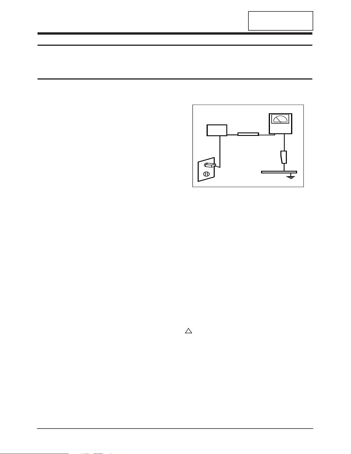
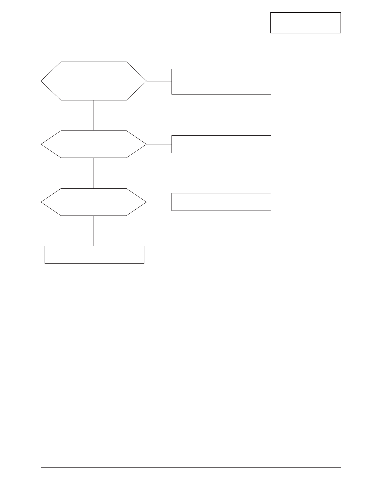
3. Leakage Current Hot Check (Figure 1-1):
WARNING: Do not use an isolation transformer during
this test.
Use a leakage current tester or a metering system
that complies with American National Standards
Institute (ANSI C101.1, Leakage Current for
Appliances), and Underwriters Laboratories (UL
Publication UL1410, 59.7).
Figure 1-1. Leakage Current Test Circuit
4. With the unit completely reassembled, plug the AC
line cord directly into a 120V AC outlet. With the
unit’s AC switch first in the ON position and then
OFF, measure the current between a known earth
ground (metal water pipe, conduit, etc.) and all
exposed metal parts, including: metal cabinets,
screwheads and control shafts. The current
measured should not exceed 0.5 milliamp. Reverse
the power-plug prongs in the AC outlet and repeat
the test.
1-1-4 Product Safety Notices
Some electrical and mechanical parts have special
safety-related characteristics which are often not
evident from visual inspection. The protection they give
may not be obtained by replacing them with
components rated for higher voltage, wattage, etc. Parts
that have special safety characteristics are identified by
on schematics and parts lists. A substitute
replacement that does not have the same safety
characteristics as the recommended replacement part
might create shock, fire and / or other hazards. Product
safety is under review continuously and new
instructions are issued whenever appropriate.
ES15N*/ES17N* 1-1

1 Precautions
CONFIDENTIAL
1-2 Servicing Precautions
WARNING: An electrolytic capacitor installed with the wrong polarity might explode.
Caution: Before servicing units covered by this service manual, read and follow the Safety Precautions
section of this manual.
Note: If unforeseen circumstances create conflict between the following servicing precautions and any of the
safety precautions, always follow the safety precautions.
1-2-1 General Servicing Precautions
1. Always unplug the unit’s AC power cord from the
AC power source and disconnect the DC Power
Jack before attempting to:
(a) remove or reinstall any component or assembly,
(b) disconnect PCB plugs or connectors, (c) connect
a test component in parallel with an electrolytic
capacitor.
2. Some components are raised above the printed
circuit board for safety. An insulation tube or tape
is sometimes used. The internal wiring is
sometimes clamped to prevent contact with
thermally hot components. Reinstall all such
elements to their original position.
3. After servicing, always check that the screws,
components and wiring have been correctly
reinstalled. Make sure that the area around the
serviced part has not been damaged.
4. Check the insulation between the blades of the AC
plug and accessible conductive parts (examples:
metal panels, input terminals and earphone jacks).
5. Insulation Checking Procedure: Disconnect the
power cord from the AC source and turn the power
switch ON. Connect an insulation resistance meter
(500 V) to the blades of the AC plug.
The insulation resistance between each blade of the
AC plug and accessible conductive parts (see
above) should be greater than 1 megohm.
6. Always connect a test instrument’s ground lead to
the instrument chassis ground before connecting
the positive lead; always remove the instrument’s
ground lead last.
1-3 Electrostatically Sensitive Devices (ESD) Precautions
Some semiconductor (solid state) devices can be easily damaged by static electricity. Such components are commonly
called Electrostatically Sensitive Devices (ESD). Examples of typical ESD devices are integrated circuits and some fieldeffect transistors. The following techniques will reduce the incidence of component damage caused by static electricity.
1. Immediately before handling any semiconductor
components or assemblies, drain the electrostatic
charge from your body by touching a known earth
ground. Alternatively, wear a discharging wriststrap device. To avoid a shock hazard, be sure to
remove the wrist strap before applying power to
the monitor.
2. After removing an ESD-equipped assembly, place it
on a conductive surface such as aluminum foil to
prevent accumulation of an electrostatic charge.
3. Do not use freon-propelled chemicals. These can
generate electrical charges sufficient to damage
ESDs.
4. Use only a grounded-tip soldering iron to solder or
desolder ESDs.
5. Use only an anti-static solder removal device. Some
solder removal devices not classified as “anti-static”
can generate electrical charges sufficient to damage
ESDs.
6. Do not remove a replacement ESD from its
protective package until you are ready to install it.
Most replacement ESDs are packaged with leads
that are electrically shorted together by conductive
foam, aluminum foil or other conductive materials.
7. Immediately before removing the protective
material from the leads of a replacement ESD,
touch the protective material to the chassis or
circuit assembly into which the device will be
installed.
Caution: Be sure no power is applied to the
chassis or circuit and observe all
other safety precautions.
8. Minimize body motions when handling
unpackaged replacement ESDs. Motions such as
brushing clothes together, or lifting your foot from
a carpeted floor can generate enough static
electricity to damage an ESD.
1-2 ES15N*/ES17N*

2 Product Specifications
2-1 Specifications
CONFIDENTIAL
Item
LCD Panel TFT-LCD panel, RGB vertical stripe, normaly TFT-LCD panel, RGB vertical stripe, normaly
white, 15-Inch viewable, 0.297 mm pixel pitch white, 17-Inch viewable, 0.264 mm pixel pitch
Scanning Frequency Horizontal : 30 kHz ~ 69 kHz (Automatic) 30 kHz ~ 81 kHz (Automatic)
Vertical : 56 Hz ~ 85 Hz (Automatic) 56 Hz ~ 85 Hz (~XGA), 60 Hz ~ 76 Hz (~SXGA)
Display Colors 16.7 Million colors
Maximum Resolution Horizontal : 1024 Pixels 1280 Pixels
Vertical : 768 Pixels 1024 Pixels
Input Video Signal Analog 0.7 Vp-p ± 5% positive at 75 Ω, internally terminated
Input Sync Signal Type : Seperate H/V Sync-on-Green,
automatic synchronization without external switch of sync type
Level : TTL level
Maximum Pixel Clock rate 95 MHz 135 MHz
Active Display
Horizontal/Vertical
AC power voltage & Frequency
Power Consumption 48 W (Max), (2W Power saurg) 58 W (Max), (2W Power saurg)
304.1 mm / 228.1 mm 338.1 mm / 270.1 mm
AC 90 ~ 264 Volts, 60 / 50 Hz ± 3 Hz
ES15N* ES17N*
Description
Dimensions
Unit (W x D x H) 18.6 x 12.4 x 2.0 Inches (474 x 317 x 51 mm)
With stand (W x D x H)
Weight 3.97 Kg (8.75 Ibs) 4.95 Kg (10.9 Ibs)
Environmental Considerations Operating Temperature : 50 °F ~ 104 °F (10 °C ~ 40 °C)
TV System
Antena Input 75Ω, Coaxial Cable
Sound Characteristic
18.6 x 15.6 x 8.0 Inches (474 x 397 x 204 mm)
Humidity : 10 % ~ 80 %
Storage Temperature : -13 °F ~ 113 °F (-25 °C ~ 45 °C)
Humidity : 5 % ~ 95 %
Tunning Frequency Synthesize
Color NTSC
Sound BTSC, ECJ, KOREA
– MAX Internal speaker Out : Right => 3W Right => 5W
Left => 3W Left => 5W
– BASS Control Range : -12dB~ + 12dB
– TREBLE Control Range : -12dB~ + 12dB
– Headphone Out: RF => 5mW max (400m Vrms)
A/V => 10mW max (580 Vrms), Max Input sound: -9dBm
– Output Frequency (TBD) : RF => 80 Hz ~ 15 kHz
A/V => 80 Hz ~ 20 kHz
20.8 x 14.4 x 2.2 Inches (530 x 367 x 57 mm)
20.8 x 17.6 x 8.0 Inches (530 x 447 x 204 mm)
ES15N*/ES17N* 2-1
2 Product Specifications
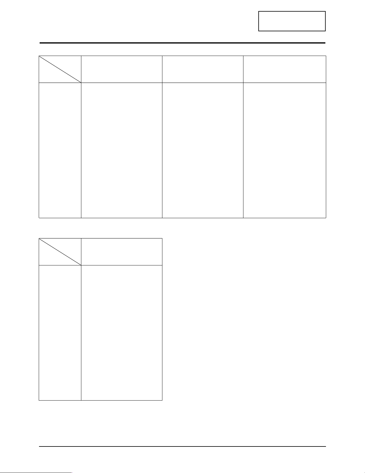
2-2 Pin Assignments
Sync
Type
Pin No.
Separate H/V Composite H/V
CONFIDENTIAL
Sync-on-green
Pin No.
10
11
12
13
14
15
1
2
3
4
5
6
7
8
9
Sync
Type
Red
Green
Blue
GND
GND (DDC Return)
GND-Red
GND-Green
GND-Blue
No Connection
GND-Sync./Self Test
GND
DDC Data
Horizontal sync.
Vertical sync.
DDC Clock
DTV 15pin connector
Red
Green
Blue
GND
GND (DDC Return)
GND-Red
GND-Green
GND-Blue
No Connection
GND-Sync./Self Test
GND
DDC Data
H/V-Sync.
Not Used
DDC Clock
Red
Green + H/V Sync.
Blue
GND
GND (DDC Return)
GND-Red
GND-Green
GND-Blue
Not Used
GND-Sync./Self Test
GND
DDC Data
Not Used
Not Used
DDC Clock
10
11
12
13
14
15
1
2
3
4
5
6
7
8
9
Red , Y
Green , Pb
Blue , Pr
GND
GND
GND-Red
GND-Green
GND-Blue
GND
No Connection
GND
No Connection
Horizontal sync.
Vertical sync.
No Connection
2-2 ES15N*/ES17N*
2 Product Specifications
QRS
P
O
Video
Sync
Sync
Horizontal
Vertical
CDE
P
O
B
A
Video
Sync
Sync
VIDEO
A
B
O
P
Q
R
S
Horizontal
Vertical
CONFIDENTIAL
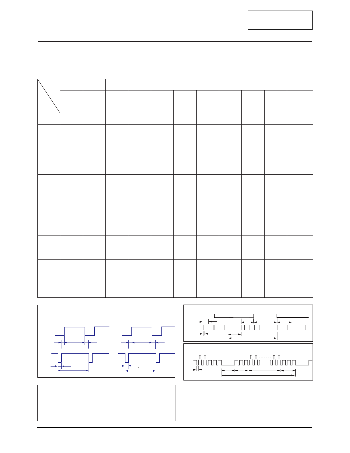
2-3 Timing Chart
This section of the service manual describes the timing that the computer industry recognizes as standard
for computer-generated video signals.
Table 2-1. Timing Chart
Mode
Timing
fH (kHz)
A µsec
B µsec
C µsec
D µsec
E µsec
fV (Hz)
O msec
P msec
Q msec
R msec
S msec
Clock
Freq.
(MHz)
VGA2/
70 Hz
720 x 400
31.469
31.777
3.813
1.589
26.058
0.318
70.087
14.268
0.064
0.858
13.155
0.191
28.322
IBM
640 x 480
VGA3/
60 Hz
31.469
31.778
3.813
1.589
26.058
0.318
59.940
16.683
0.064
0.794
15.761
0.064
25.175
640/75 Hz
640 x 480
37.500
26.667
2.032
3.810
20.317
0.508
75.000
13.333
0.080
0.427
12.800
0.027
31.500
640/85 Hz
640 x 480
43.269
23.111
1.556
2.222
17.778
1.556
85.008
11.764
0.671
0.578
11.093
0.023
49.500
800/75 Hz
800 x 600
46.875
21.333
1.616
3.232
16.162
0.323
75.000
13.333
0.064
0.448
12.800
0.021
49.500
800/85 Hz
800 x 600
53.674
18.631
1.138
2.702
14.222
0.569
85.061
11.756
0.056
0.503
11.179
0.019
56.250
VESA
1024/60Hz
1024 x 768
48.363
20.677
2.092
2.462
15.754
0.369
60.004
16.666
0.124
0.600
15.880
0.062
75.000
1024/75Hz
1024 x 768
60.023
16.660
1.219
2.235
13.003
0.203
75.029
13.328
0.050
0.466
12.795
0.017
78.750
1024/85Hz
1024x768
68.677
14.561
1.016
2.201
10.836
0.508
84.997
11.765
0.044
0.524
11.183
0.015
94.500
1280/76Hz
1280x1024
(17” Only) (17” Only)
81.129
16.640
1280/75Hz
1280x1024
79.976
12.504
6.400
2.880
3.200
76.106
10.660
75.025
13.329
0.080
3.200
12.804
0.020
135.000
135.000
1.067
1.837
9.481
0.119
0.038
0.475
0.013
Polarity
H.Sync
V.Sync
Remark
A : Line time total B : Horizontal sync width O : Frame time total P : Vertical sync width
C : Back porch D : Active time Q : Back porch R : Active time
E : Front porch S : Front porch
ES15N*/ES17N* 2-3
Sync
Negative
Positive
Separate
Video
C D
Negative
Negative
Separate
Separate Sync
E
Negative
Negative
Separate
Negative
Negative
Separate
Video
Q R S
Positive
Positive
Separate
Positive
Positive
Separate
Negative
Negative
Separate
Positive
Positive
Separate
Positive
Positive
Separate
H/V Composite Sync
Negative
Negative
Com.
Positive
Positive
Separate
Sync-on-Green
Sync
B
A
P
O
Green
Horizontal
Vertical
P
B
Q
R
O
S

2 Product Specifications
Memo
CONFIDENTIAL
2-4 ES15N*/ES17N*
CONFIDENTIAL
3 Disassembly and Reassembly
This section of the service manual describes the disassembly and reassembly procedures for the
ES15N*/ES17N* monitor.
WARNING: This monitor contains electrostatically sensitive devices. Use caution when handling
these components.
3-1 Disassembly
Cautions:1. Disconnect the monitor from the power source before disassembly.
2. Follow these directions carefully; never use metal instruments to pry apart the cabinet.
3-1 General Alignment Instuction
1. Usually, a color TV-VCR needs only slight
touch-up adjustment upon installation.
Check the basic characteristics such as height,
horizontal and vertical sync.
2. Use the specified test equipment or its
equivalent.
3. Correct impedance matching is essential.
4. Avoid overload. Excessive signal from a
sweep generator might overload the front-end
of the TV. When inserting signal markers,
do not allow the marker generator to distort
test result.
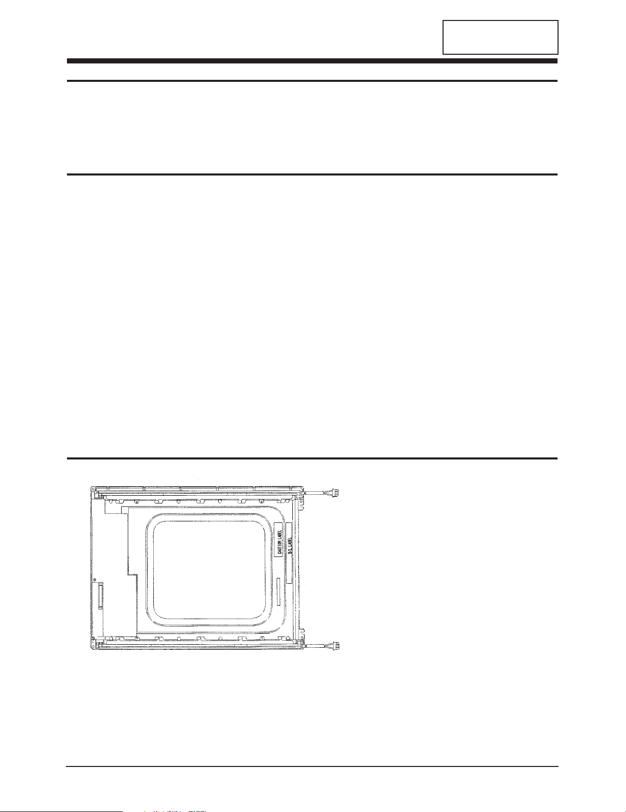
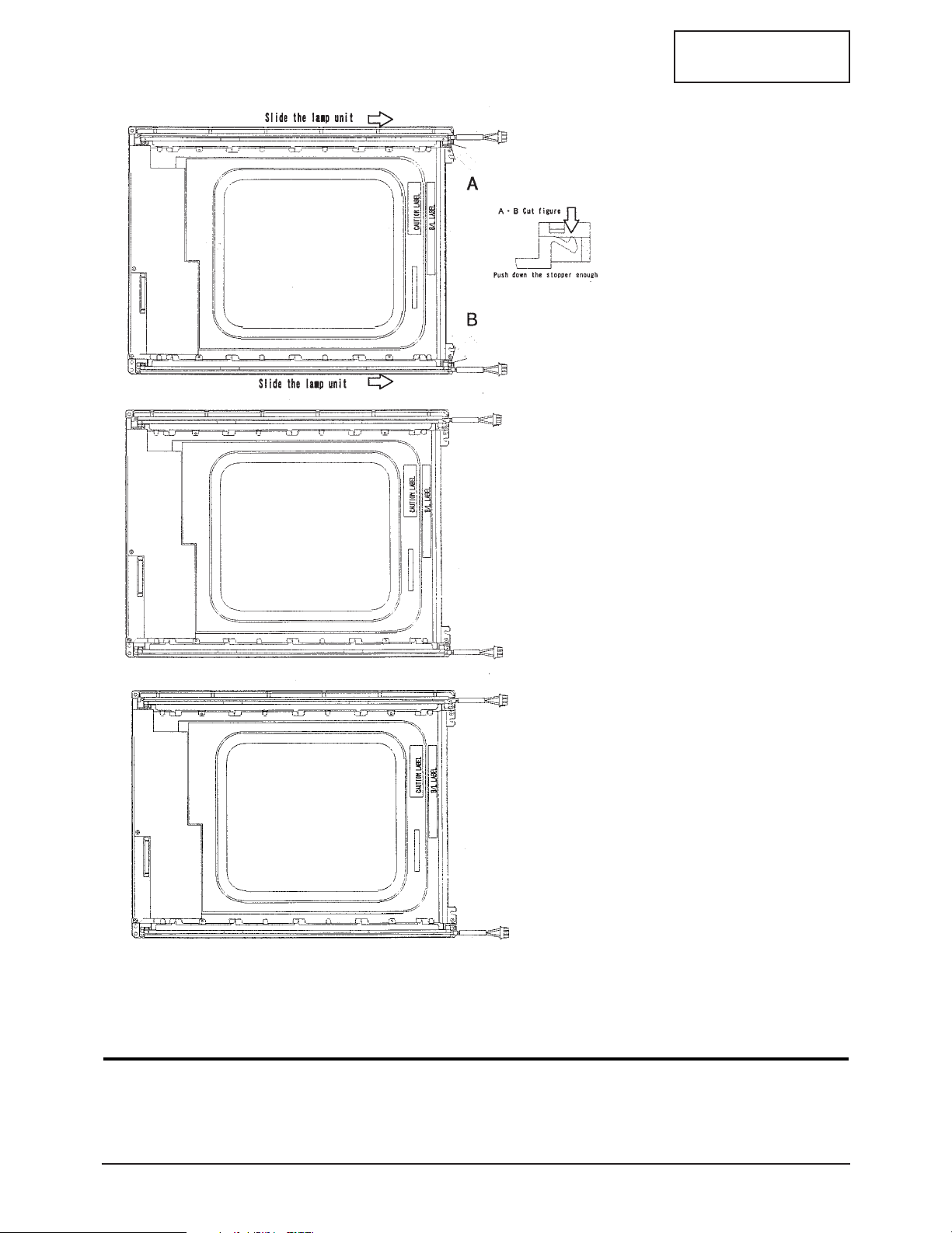
3-2 Replacement Order of Lamp Assemblies
5. Connect the TV only to an DC power source
with voltage and frequency as specified on
the backcover nameplate.
6. Do not attempt to connect or disconnect any
wire while the TV is turned on. Make sure
that the power cord is disconnected before
replacing any parts.
7. To protect aganist shock hazard,use an
isolation transform.
1. After confirm there is nothing
on the desk
Turn the LCD module over
and put it on a flat desk set to
the ground.
ES15N*/ES17N* 3-1
3 Disassembly and Reassembly
CONFIDENTIAL
2. Push down the stopper and
slide the lamp unit.
3. Please take out the lamp
units from the LCD module.
4. Please fix the new lamp
units on the LCD module :
opposite process 2 and 3
* Replacement of lamp unit should be done at the power off state and recommended clean bench
condition.
3-3 Reassembly
Reassembly procedures are in the reverse order of Disassembly procedures.
3-2 ES15N*/ES17N*

CONFIDENTIAL
4 Alignments and Adjustments
4-1 General Alignment Instruction
1. Usually, a color TV-VCR needs only slight touch-up adjustment upon installation.
Check the basic characteristics such as height, horizontal and vertical sync.
2. Use the specified test equipment or its equivalent.
3. Correct impedance matching is essential.
4. Avoid overload. Excessive signal from a sweep generator might overload the front-end
of the TV. When inserting signal markers,do not allow the marker generator to distort
test result.
5. Connect the TV only to an DC power source with voltage and frequency as specified on
the backcover nameplate.
6. Do not attempt to connect or disconnect any wire while the TV is turned on. Make sure
that the power cord is disconnected before replacing any parts.
7. To protect aganist shock hazard,use an isolation transform.
ES15N*/ES17N* 4-1

4 Alignments and Adjustments
Memo
CONFIDENTIAL
4-2 ES15N*/ES17N*
5 Troubleshooting
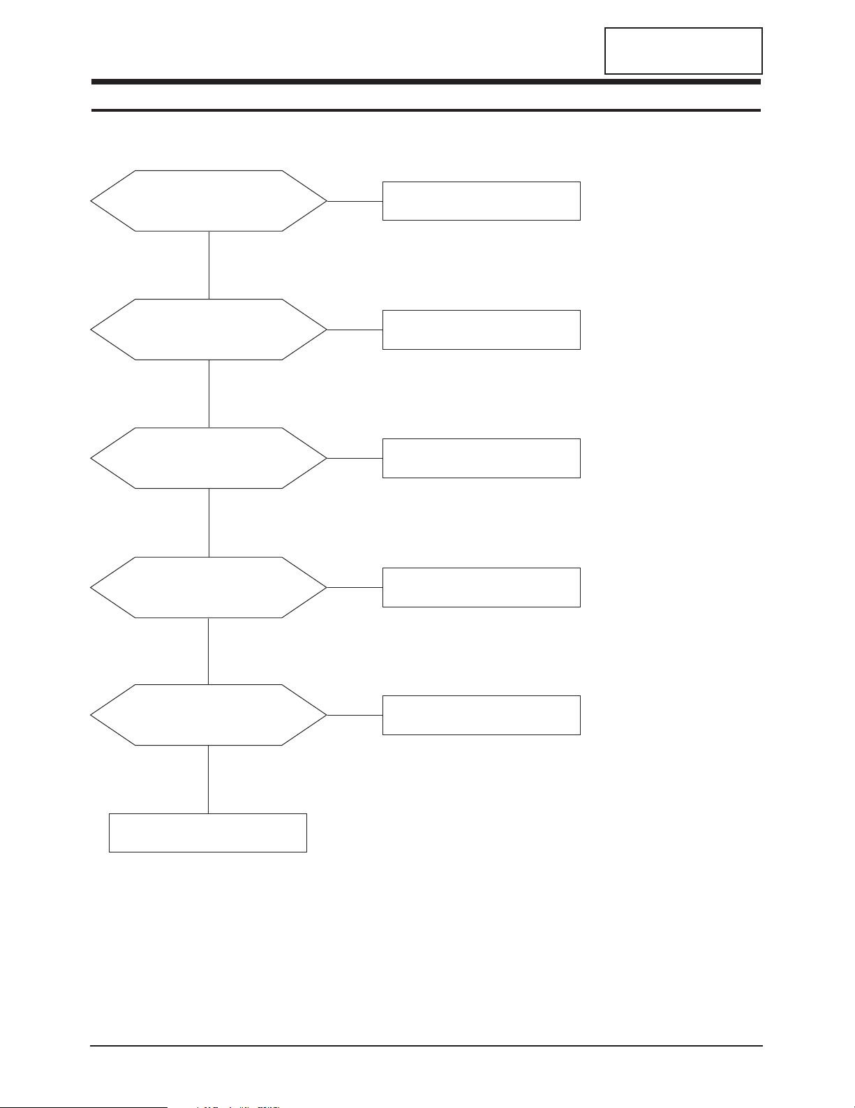
5-1 No Power
CONFIDENTIAL
Does proper DC 14 V appear at
DC jack connected to CN801?
Yes
Does proper DC 5 V appear at
Pin 1 of IC803?
Yes
Does proper DC 14V appear at
Pin 2 of IC803?
Yes
Does proper DC 3.3 V appear at
Pin 1 of IC804?
No
Check SMPS PCB and Adapter.
No
Check IC803.
No
Check IC803.
No
Check IC804.
Yes
Does proper DC 2.5 V appear at
Pin 4 of IC105?
Yes
Check IC908.
ES15N*/ES17N* 5-1
No
Check IC105.
5 Troubleshooting
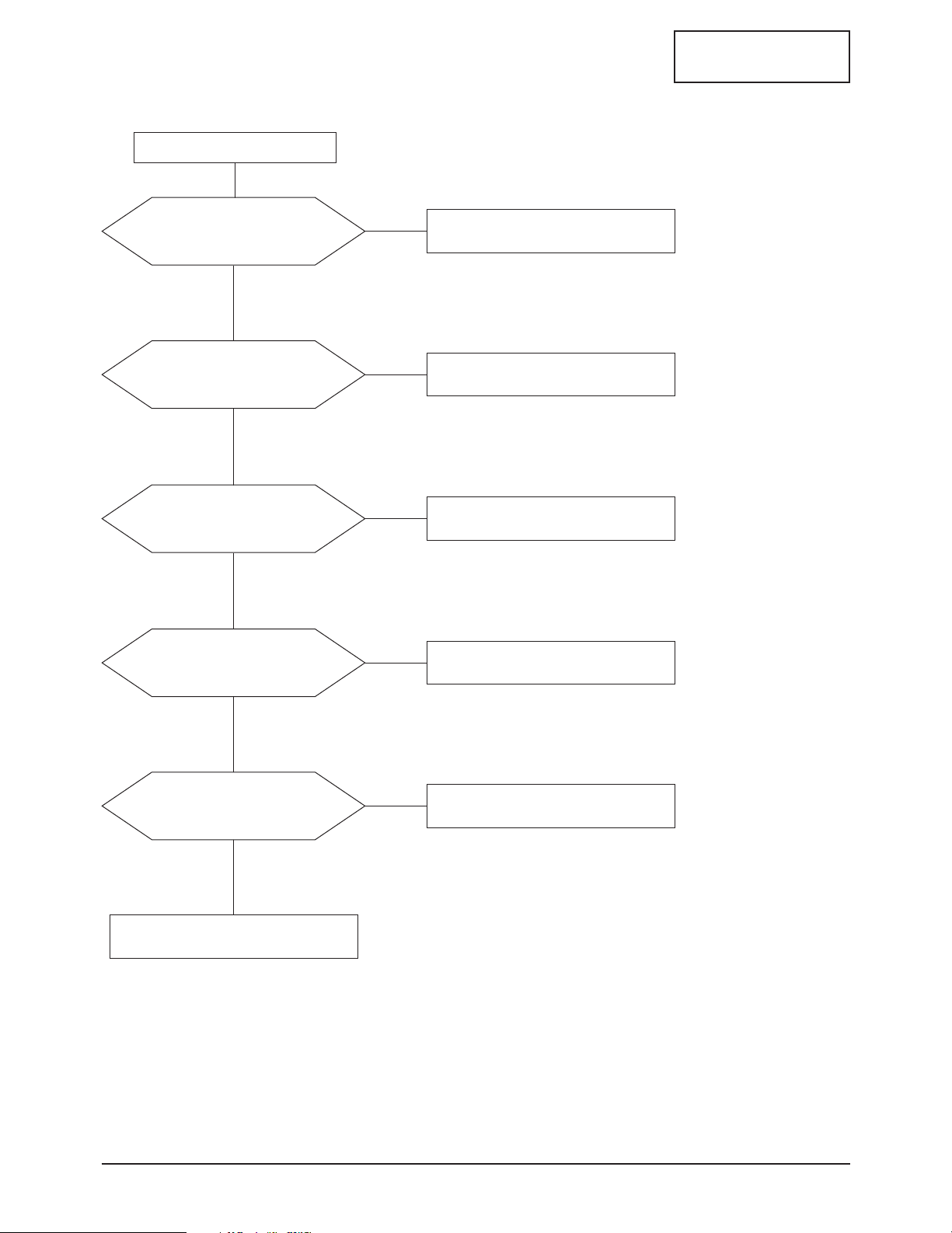
5-2 No Video (PC Signal)
Power indicator is green.
Yes
CONFIDENTIAL
Does the signal appear
at C106, C107, C108
of R, G, B input?
Yes
Does the clock pulse
appear at X100?
Yes
Does the clock pulse appear at
output of RA102 ~ RA107?
Yes
Does the clock pulse
appear at R401?
No
Check CN100.
No
Check X100 and related circuit of X100.
No
Check related circuit of IC102.
No
Check R401 and related circuit of R401.
Yes
Does the clock pulse appear at
output of R605 ~ R614?
Yes
Replace LCD Panel.
5-2 ES15N*/ES17N*
No
Replace R605 ~ R604.

5 Troubleshooting
5-3 No Picture (TV, Video, S-Video, Scart Video)
CONFIDENTIAL
Check Pin 71, 72 (S-Video)
and Pin 73 (VCR) and Pin 74
and Pin 75 (RF-CVBS)
of IC201 (VPC3230D).
Yes
Does the signal appear at
RA200 ~RA203?
Yes
Does the signal appear at
RA300 ~ RA303 of related
IC300 (FLI2200)?
Yes
No
No
No
Check the CN806 (Tuner) and the
CN802 (VCR connector).
Check the IC201 (VPC3230D)
and related circuit of IC201.
Check the IC300 and
related circuit of IC300.
Check the IC400 and R422 ~ R426.
ES15N*/ES17N* 5-3
5 Troubleshooting
5-4 No Sound
CONFIDENTIAL
Does the signal appear at
Pin 67 (Tuner sound signal) and
Pin 57, 56 (PC sound) and Pin 51, 50
(VCR sound) of IC 700 (MSP3451)?
Yes
Does the signal appear at Pin 27,
28 of IC700 (MSP3451)?
Yes
Does the signal appear
at L702 ~L705?
Yes
No
No
No
Check the CN803 (PC conector) and the
CN802 (VCR connector) and the
CN200 the CN806 (Tuner).
Check the IC700 and
related circuit of IC700.
Check the IC702 (Audio amp) and
related circuit of IC702.
Replace the speaker.
5-4 ES15N*/ES17N*
CONFIDENTIAL
ES15N*/ES17N* 6-1
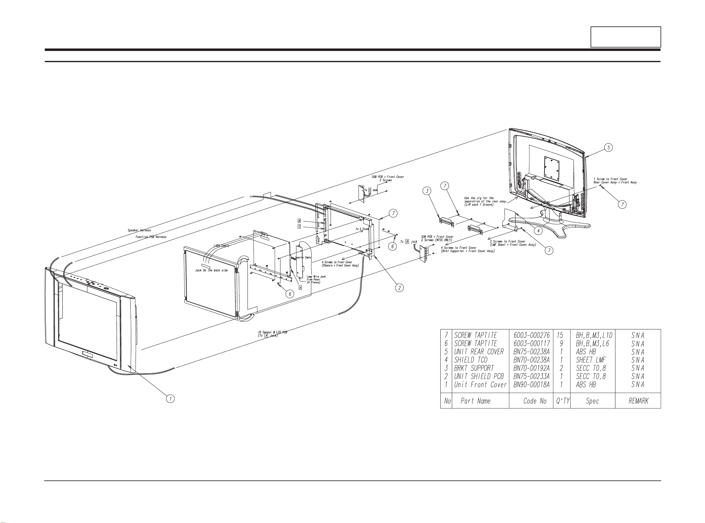
6 Exploded View and Parts List
6-1 ES15N*
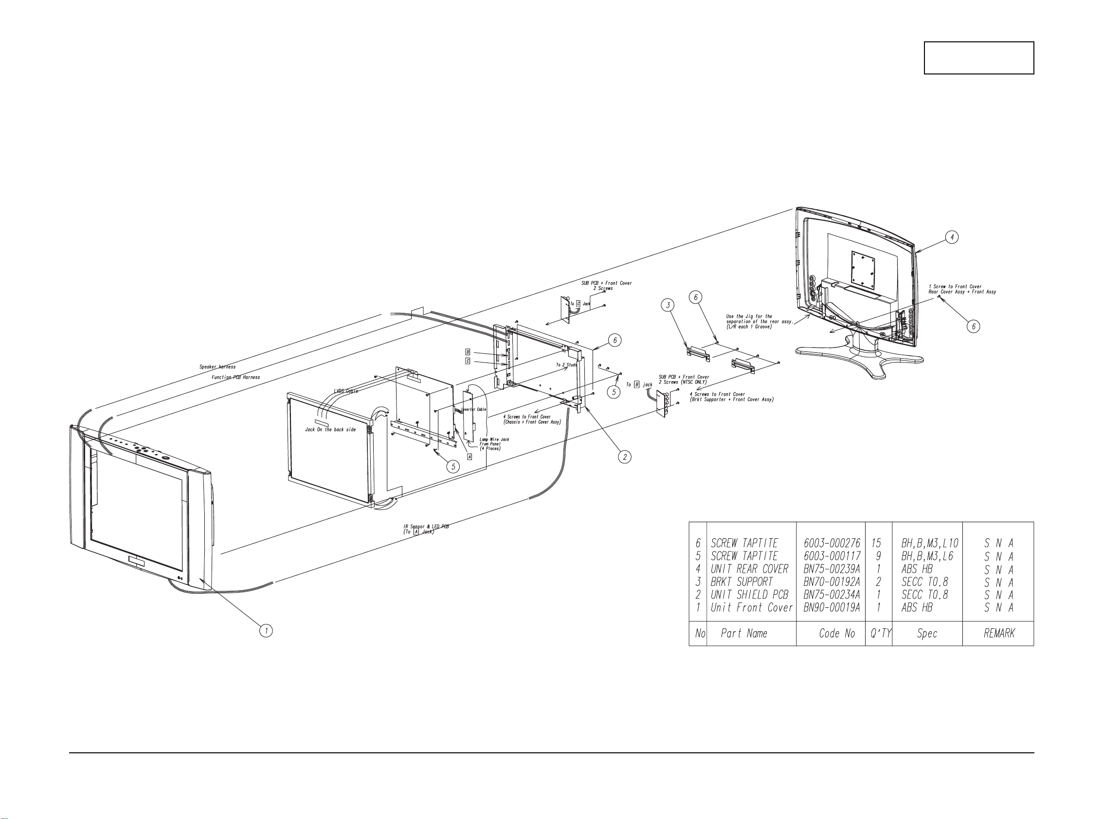
6-2 ES17N*
6 Exploded View & Parts List
6-2 ES15N*/ES17N*
CONFIDENTIAL
CONFIDENTIAL
7 Electrical Parts List
7-1-1 ES15N* Main PCB Parts
Loc. No. Code No. Description Specification Remarks
- BN94-00266A ASSY PCB MAIN ES15NS SNA
- BN97-00054T ASSY MICOM ES15AS SNA
BD810 2701-000146 INDUCTOR-AXIAL 2.2uH,10%,2.5x3.4mm SNA
BD811 2701-000146 INDUCTOR-AXIAL 2.2uH,10%,2.5x3.4mm SNA
C806 2409-001004 C-ORGANIC 100uF,20%,16V,LL,BK,8x10.5mm,3
C848 2401-002286 C-AL 470uF,20%,16V,WT,TP,10x12.5,5
C849 2401-002286 C-AL 470uF,20%,16V,WT,TP,10x12.5,5
CIS BN39-00047A CBF-HARNESS
CIS BN39-00204A LEAD CONNECTOR ASSY
CIS BN90-00030A ASSY SHIELD-D-SUB ES15NS,-,SPTE,T0.5,-,-,-,CIS BN90-00031A ASSY SHIELD-PCB ES15NS,-,-,SECC T0.8,-,-,-,CIS BN46-00009N MICOM-S/W ES15NS,-,-,-,-,-,- SNA
CN100 3701-001219 CONNECTOR-DSUB 15P,3R,FEMALE,ANGLE,AUF
CN700 3711-004270 CONNECTOR-HEADER BOX,2P,1R,2MM,ANGLE,SN SNA
CN701 3711-004386 CONNECTOR-HEADER BOX,3P,1R,2mm,ANGLE,SN SNA
CN801 3722-000117 JACK-DC POWER 3P,3.5mm,AG,BLK,NO SNA
CN803 3722-001055 JACK-PHONE 5P/2C,3.6PI,AG,BLK,#16-22 SNA
CN806 BH40-00004A TUNER
CN808 3722-001547 JACK-PIN 3P,3.5mm,AU,GRN/BLU/RED,CN809 3722-001756 JACK-PIN 2P,-,AU,WHT/RED,IC901 1102-001128 IC-EPROM
IC901_SOCK 3704-000255 SOCKET-IC 32P,DIP,SN,2.54mm
L610 2701-000112 INDUCTOR-AXIAL 100uH,10%,3x7mm
L611 2701-000112 INDUCTOR-AXIAL 100uH,10%,3x7mm
L802 2701-000146 INDUCTOR-AXIAL 2.2uH,10%,2.5x3.4mm SNA
M/PCB+SH/PCB
R299 2003-000797 R-METAL OXIDE(S) 8.2ohm,5%,3W,AA,TP,6x16mm
SH/PCB+SH/D_SUB
- BN97-00066A ASSY AUTO-MAIN ES15NS SNA
BD100 3301-001163 CORE-FERRITE BEAD AB,80ohm,2x1.25x1mm,300mA,TP,FERRITE,0.08ohm SNA
BD101 3301-001163 CORE-FERRITE BEAD AB,80ohm,2x1.25x1mm,300mA,TP,FERRITE,0.08ohm SNA
BD102 3301-001163 CORE-FERRITE BEAD AB,80ohm,2x1.25x1mm,300mA,TP,FERRITE,0.08ohm SNA
BD104 3301-001163 CORE-FERRITE BEAD AB,80ohm,2x1.25x1mm,300mA,TP,FERRITE,0.08ohm SNA
BD105 3301-001163 CORE-FERRITE BEAD AB,80ohm,2x1.25x1mm,300mA,TP,FERRITE,0.08ohm SNA
BD106 3301-001163 CORE-FERRITE BEAD AB,80ohm,2x1.25x1mm,300mA,TP,FERRITE,0.08ohm SNA
BD107 3301-001163 CORE-FERRITE BEAD AB,80ohm,2x1.25x1mm,300mA,TP,FERRITE,0.08ohm SNA
BD108 3301-001163 CORE-FERRITE BEAD AB,80ohm,2x1.25x1mm,300mA,TP,FERRITE,0.08ohm SNA
BD109 3301-001163 CORE-FERRITE BEAD AB,80ohm,2x1.25x1mm,300mA,TP,FERRITE,0.08ohm SNA
BD111 3301-001236 CORE-FERRITE BEAD AB,60ohm,1.6x0.8x0.8mm,200mA,TP,H,0.7ohm
BD112 3301-001236 CORE-FERRITE BEAD AB,60ohm,1.6x0.8x0.8mm,200mA,TP,H,0.7ohm
BD113 3301-001236 CORE-FERRITE BEAD AB,60ohm,1.6x0.8x0.8mm,200mA,TP,H,0.7ohm
BD115 3301-001145 CORE-FERRITE BEAD AB,4.5x1.6x1.6mm,-,- SNA
BD200 3301-001163 CORE-FERRITE BEAD AB,80ohm,2x1.25x1mm,300mA,TP,FERRITE,0.08ohm SNA
BD201 3301-001163 CORE-FERRITE BEAD AB,80ohm,2x1.25x1mm,300mA,TP,FERRITE,0.08ohm SNA
BD202 3301-001163 CORE-FERRITE BEAD AB,80ohm,2x1.25x1mm,300mA,TP,FERRITE,0.08ohm SNA
BD204 3301-001163 CORE-FERRITE BEAD AB,80ohm,2x1.25x1mm,300mA,TP,FERRITE,0.08ohm SNA
BD205 3301-001163 CORE-FERRITE BEAD AB,80ohm,2x1.25x1mm,300mA,TP,FERRITE,0.08ohm SNA
BD206 3301-001163 CORE-FERRITE BEAD AB,80ohm,2x1.25x1mm,300mA,TP,FERRITE,0.08ohm SNA
BD300 3301-001163 CORE-FERRITE BEAD AB,80ohm,2x1.25x1mm,300mA,TP,FERRITE,0.08ohm SNA
BD400 3301-001163 CORE-FERRITE BEAD AB,80ohm,2x1.25x1mm,300mA,TP,FERRITE,0.08ohm SNA
BD401 3301-001163 CORE-FERRITE BEAD AB,80ohm,2x1.25x1mm,300mA,TP,FERRITE,0.08ohm SNA
BD402 3301-001163 CORE-FERRITE BEAD AB,80ohm,2x1.25x1mm,300mA,TP,FERRITE,0.08ohm SNA
BD600 3301-001163 CORE-FERRITE BEAD AB,80ohm,2x1.25x1mm,300mA,TP,FERRITE,0.08ohm SNA
BD601 3301-001163 CORE-FERRITE BEAD AB,80ohm,2x1.25x1mm,300mA,TP,FERRITE,0.08ohm SNA
BD602 3301-001163 CORE-FERRITE BEAD AB,80ohm,2x1.25x1mm,300mA,TP,FERRITE,0.08ohm SNA
BD700 3301-001145 CORE-FERRITE BEAD AB,4.5x1.6x1.6mm,-,- SNA
BD800 3301-001163 CORE-FERRITE BEAD AB,80ohm,2x1.25x1mm,300mA,TP,FERRITE,0.08ohm SNA
BD801 3301-001163 CORE-FERRITE BEAD AB,80ohm,2x1.25x1mm,300mA,TP,FERRITE,0.08ohm SNA
6003-000117 SCREW-TAPTITE BH,+,B,M3,L6,ZPC(YEL),SWRCH18A SNA
6003-000117 SCREW-TAPTITE BH,+,B,M3,L6,ZPC(YEL),SWRCH18A SNA
100MM,100MM,BLU/WHT/GRY,UL1061,AWG28,51021-1200
ES15AS,UL2835##28,UL/CSA,20P,-,-,#30,12507HS-20,12507HS-20,BK,-,-,130MM,2835#28,
TCLN9081PA27D,-,NTSC,181CH,45.75MHZ,-,-,-,F-CON,ASYMM,5V,TR,-,-,-,-,-,-,-,-,-
M27C2001,256KX8BIT,PDIP,32P,535MIL,55NS,5V,10%,PLASTIC,0TO+70C,-,-,ST
ES15N*/ES17N* 7-1

7 Electrical Parts List
Loc. No. Code No. Description Specification Remarks
BD802 3301-001163 CORE-FERRITE BEAD AB,80ohm,2x1.25x1mm,300mA,TP,FERRITE,0.08ohm SNA
BD803 3301-001163 CORE-FERRITE BEAD AB,80ohm,2x1.25x1mm,300mA,TP,FERRITE,0.08ohm SNA
BD804 3301-001163 CORE-FERRITE BEAD AB,80ohm,2x1.25x1mm,300mA,TP,FERRITE,0.08ohm SNA
BD805 3301-001163 CORE-FERRITE BEAD AB,80ohm,2x1.25x1mm,300mA,TP,FERRITE,0.08ohm SNA
BD806 3301-001163 CORE-FERRITE BEAD AB,80ohm,2x1.25x1mm,300mA,TP,FERRITE,0.08ohm SNA
BD807 3301-001163 CORE-FERRITE BEAD AB,80ohm,2x1.25x1mm,300mA,TP,FERRITE,0.08ohm SNA
BD808 3301-001163 CORE-FERRITE BEAD AB,80ohm,2x1.25x1mm,300mA,TP,FERRITE,0.08ohm SNA
BD809 3301-001163 CORE-FERRITE BEAD AB,80ohm,2x1.25x1mm,300mA,TP,FERRITE,0.08ohm SNA
BD812 3301-001163 CORE-FERRITE BEAD AB,80ohm,2x1.25x1mm,300mA,TP,FERRITE,0.08ohm SNA
BD813 3301-001163 CORE-FERRITE BEAD AB,80ohm,2x1.25x1mm,300mA,TP,FERRITE,0.08ohm SNA
BD814 3301-001163 CORE-FERRITE BEAD AB,80ohm,2x1.25x1mm,300mA,TP,FERRITE,0.08ohm SNA
BD815 3301-001163 CORE-FERRITE BEAD AB,80ohm,2x1.25x1mm,300mA,TP,FERRITE,0.08ohm SNA
BD816 3301-001163 CORE-FERRITE BEAD AB,80ohm,2x1.25x1mm,300mA,TP,FERRITE,0.08ohm SNA
BD820 3301-001163 CORE-FERRITE BEAD AB,80ohm,2x1.25x1mm,300mA,TP,FERRITE,0.08ohm SNA
BD822 3301-001163 CORE-FERRITE BEAD AB,80ohm,2x1.25x1mm,300mA,TP,FERRITE,0.08ohm SNA
BD823 3301-001163 CORE-FERRITE BEAD AB,80ohm,2x1.25x1mm,300mA,TP,FERRITE,0.08ohm SNA
BD824 3301-001163 CORE-FERRITE BEAD AB,80ohm,2x1.25x1mm,300mA,TP,FERRITE,0.08ohm SNA
BD827 3301-001163 CORE-FERRITE BEAD AB,80ohm,2x1.25x1mm,300mA,TP,FERRITE,0.08ohm SNA
BD828 3301-001163 CORE-FERRITE BEAD AB,80ohm,2x1.25x1mm,300mA,TP,FERRITE,0.08ohm SNA
BD829 3301-001163 CORE-FERRITE BEAD AB,80ohm,2x1.25x1mm,300mA,TP,FERRITE,0.08ohm SNA
BD830 3301-001163 CORE-FERRITE BEAD AB,80ohm,2x1.25x1mm,300mA,TP,FERRITE,0.08ohm SNA
BD831 3301-001163 CORE-FERRITE BEAD AB,80ohm,2x1.25x1mm,300mA,TP,FERRITE,0.08ohm SNA
BD832 3301-001163 CORE-FERRITE BEAD AB,80ohm,2x1.25x1mm,300mA,TP,FERRITE,0.08ohm SNA
BD833 3301-001163 CORE-FERRITE BEAD AB,80ohm,2x1.25x1mm,300mA,TP,FERRITE,0.08ohm SNA
BD900 3301-001163 CORE-FERRITE BEAD AB,80ohm,2x1.25x1mm,300mA,TP,FERRITE,0.08ohm SNA
BD901 3301-001163 CORE-FERRITE BEAD AB,80ohm,2x1.25x1mm,300mA,TP,FERRITE,0.08ohm SNA
BD902 3301-001163 CORE-FERRITE BEAD AB,80ohm,2x1.25x1mm,300mA,TP,FERRITE,0.08ohm SNA
BD903 3301-001163 CORE-FERRITE BEAD AB,80ohm,2x1.25x1mm,300mA,TP,FERRITE,0.08ohm SNA
BD904 3301-001163 CORE-FERRITE BEAD AB,80ohm,2x1.25x1mm,300mA,TP,FERRITE,0.08ohm SNA
BD905 3301-001163 CORE-FERRITE BEAD AB,80ohm,2x1.25x1mm,300mA,TP,FERRITE,0.08ohm SNA
BD906 3301-001163 CORE-FERRITE BEAD AB,80ohm,2x1.25x1mm,300mA,TP,FERRITE,0.08ohm SNA
BD907 3301-001163 CORE-FERRITE BEAD AB,80ohm,2x1.25x1mm,300mA,TP,FERRITE,0.08ohm SNA
C100 2203-000189 C-CERAMIC,CHIP 100nF,+80-20%,25V,Y5V,TP,1608,
C101 2203-005065 C-CERAMIC,CHIP 1000nF,+80-20%,10V,Y5V,TP,1608
C102 2203-005065 C-CERAMIC,CHIP 1000nF,+80-20%,10V,Y5V,TP,1608
C103 2203-000697 C-CERAMIC,CHIP 0.002nF,0.25pF,50V,NP0,TP,1608
C104 2203-000697 C-CERAMIC,CHIP 0.002nF,0.25pF,50V,NP0,TP,1608
C105 2203-000697 C-CERAMIC,CHIP 0.002nF,0.25pF,50V,NP0,TP,1608
C106 2203-005065 C-CERAMIC,CHIP 1000nF,+80-20%,10V,Y5V,TP,1608
C107 2203-005065 C-CERAMIC,CHIP 1000nF,+80-20%,10V,Y5V,TP,1608
C108 2203-005065 C-CERAMIC,CHIP 1000nF,+80-20%,10V,Y5V,TP,1608
C109 2203-000440 C-CERAMIC,CHIP 1nF,10%,50V,X7R,TP,1608,C110 2203-000189 C-CERAMIC,CHIP 100nF,+80-20%,25V,Y5V,TP,1608,
C1101 2203-000257 C-CERAMIC,CHIP 10nF,10%,50V,X7R,TP,1608
C1102 2203-000257 C-CERAMIC,CHIP 10nF,10%,50V,X7R,TP,1608
C1103 2203-000257 C-CERAMIC,CHIP 10nF,10%,50V,X7R,TP,1608
C1105 2203-000998 C-CERAMIC,CHIP 0.047nF,5%,50V,NP0,TP,1608
C111 2203-000189 C-CERAMIC,CHIP 100nF,+80-20%,25V,Y5V,TP,1608,
C112 2203-005065 C-CERAMIC,CHIP 1000nF,+80-20%,10V,Y5V,TP,1608
C113 2203-005065 C-CERAMIC,CHIP 1000nF,+80-20%,10V,Y5V,TP,1608
C114 2203-000189 C-CERAMIC,CHIP 100nF,+80-20%,25V,Y5V,TP,1608,
C115 2203-000440 C-CERAMIC,CHIP 1nF,10%,50V,X7R,TP,1608,C116 2203-000189 C-CERAMIC,CHIP 100nF,+80-20%,25V,Y5V,TP,1608,
C117 2402-000176 C-AL,SMD 10uF,20%,16V,GP,TP,4.3x4.3x5.4
C118 2203-000440 C-CERAMIC,CHIP 1nF,10%,50V,X7R,TP,1608,C119 2203-005065 C-CERAMIC,CHIP 1000nF,+80-20%,10V,Y5V,TP,1608
C120 2203-005065 C-CERAMIC,CHIP 1000nF,+80-20%,10V,Y5V,TP,1608
C121 2203-000440 C-CERAMIC,CHIP 1nF,10%,50V,X7R,TP,1608,C122 2203-000189 C-CERAMIC,CHIP 100nF,+80-20%,25V,Y5V,TP,1608,
C123 2203-000189 C-CERAMIC,CHIP 100nF,+80-20%,25V,Y5V,TP,1608,
C124 2203-005065 C-CERAMIC,CHIP 1000nF,+80-20%,10V,Y5V,TP,1608
CONFIDENTIAL
7-2 ES15N*/ES17N*

7 Electrical Parts List
Loc. No. Code No. Description Specification Remarks
C125 2203-000189 C-CERAMIC,CHIP 100nF,+80-20%,25V,Y5V,TP,1608,
C126 2203-000189 C-CERAMIC,CHIP 100nF,+80-20%,25V,Y5V,TP,1608,
C127 2203-005065 C-CERAMIC,CHIP 1000nF,+80-20%,10V,Y5V,TP,1608
C128 2203-005065 C-CERAMIC,CHIP 1000nF,+80-20%,10V,Y5V,TP,1608
C129 2203-000189 C-CERAMIC,CHIP 100nF,+80-20%,25V,Y5V,TP,1608,
C130 2203-005065 C-CERAMIC,CHIP 1000nF,+80-20%,10V,Y5V,TP,1608
C131 2203-005065 C-CERAMIC,CHIP 1000nF,+80-20%,10V,Y5V,TP,1608
C132 2203-000189 C-CERAMIC,CHIP 100nF,+80-20%,25V,Y5V,TP,1608,
C133 2203-000189 C-CERAMIC,CHIP 100nF,+80-20%,25V,Y5V,TP,1608,
C134 2402-000176 C-AL,SMD 10uF,20%,16V,GP,TP,4.3x4.3x5.4
C137 2203-000189 C-CERAMIC,CHIP 100nF,+80-20%,25V,Y5V,TP,1608,
C138 2203-005065 C-CERAMIC,CHIP 1000nF,+80-20%,10V,Y5V,TP,1608
C139 2203-005065 C-CERAMIC,CHIP 1000nF,+80-20%,10V,Y5V,TP,1608
C140 2203-000189 C-CERAMIC,CHIP 100nF,+80-20%,25V,Y5V,TP,1608,
C141 2203-005065 C-CERAMIC,CHIP 1000nF,+80-20%,10V,Y5V,TP,1608
C142 2203-005065 C-CERAMIC,CHIP 1000nF,+80-20%,10V,Y5V,TP,1608
C143 2203-000257 C-CERAMIC,CHIP 10nF,10%,50V,X7R,TP,1608
C144 2203-000189 C-CERAMIC,CHIP 100nF,+80-20%,25V,Y5V,TP,1608,
C145 2203-000189 C-CERAMIC,CHIP 100nF,+80-20%,25V,Y5V,TP,1608,
C146 2203-005065 C-CERAMIC,CHIP 1000nF,+80-20%,10V,Y5V,TP,1608
C147 2203-005065 C-CERAMIC,CHIP 1000nF,+80-20%,10V,Y5V,TP,1608
C148 2203-000384 C-CERAMIC,CHIP 0.015nF,5%,50V,NP0,TP,1608
C149 2203-000189 C-CERAMIC,CHIP 100nF,+80-20%,25V,Y5V,TP,1608,
C150 2402-000176 C-AL,SMD 10uF,20%,16V,GP,TP,4.3x4.3x5.4
C151 2203-001158 C-CERAMIC,CHIP 0.068nF,5%,50V,NP0,TP,2012
C152 2203-001158 C-CERAMIC,CHIP 0.068nF,5%,50V,NP0,TP,2012
C153 2203-005065 C-CERAMIC,CHIP 1000nF,+80-20%,10V,Y5V,TP,1608
C154 2203-005065 C-CERAMIC,CHIP 1000nF,+80-20%,10V,Y5V,TP,1608
C155 2203-000257 C-CERAMIC,CHIP 10nF,10%,50V,X7R,TP,1608
C156 2203-000189 C-CERAMIC,CHIP 100nF,+80-20%,25V,Y5V,TP,1608,
C157 2203-000257 C-CERAMIC,CHIP 10nF,10%,50V,X7R,TP,1608
C158 2203-000189 C-CERAMIC,CHIP 100nF,+80-20%,25V,Y5V,TP,1608,
C159 2203-000189 C-CERAMIC,CHIP 100nF,+80-20%,25V,Y5V,TP,1608,
C160 2203-000257 C-CERAMIC,CHIP 10nF,10%,50V,X7R,TP,1608
C161 2203-000189 C-CERAMIC,CHIP 100nF,+80-20%,25V,Y5V,TP,1608,
C162 2203-000189 C-CERAMIC,CHIP 100nF,+80-20%,25V,Y5V,TP,1608,
C163 2203-000257 C-CERAMIC,CHIP 10nF,10%,50V,X7R,TP,1608
C164 2203-000189 C-CERAMIC,CHIP 100nF,+80-20%,25V,Y5V,TP,1608,
C165 2203-000189 C-CERAMIC,CHIP 100nF,+80-20%,25V,Y5V,TP,1608,
C166 2203-000257 C-CERAMIC,CHIP 10nF,10%,50V,X7R,TP,1608
C167 2203-000189 C-CERAMIC,CHIP 100nF,+80-20%,25V,Y5V,TP,1608,
C168 2203-000189 C-CERAMIC,CHIP 100nF,+80-20%,25V,Y5V,TP,1608,
C169 2402-000176 C-AL,SMD 10uF,20%,16V,GP,TP,4.3x4.3x5.4
C170 2203-005005 C-CERAMIC,CHIP 100nF,10%,16V,X7R,TP,1608
C171 2203-000189 C-CERAMIC,CHIP 100nF,+80-20%,25V,Y5V,TP,1608,
C172 2203-000189 C-CERAMIC,CHIP 100nF,+80-20%,25V,Y5V,TP,1608,
C173 2402-000108 C-AL,SMD 10uF,20%,16V,WT,TP,4.3x4.3x5.4
C174 2203-000189 C-CERAMIC,CHIP 100nF,+80-20%,25V,Y5V,TP,1608,
C175 2402-000179 C-AL,SMD 47uF,20%,16V,GP,TP,6.6x6.6x5.4
C176 2203-000189 C-CERAMIC,CHIP 100nF,+80-20%,25V,Y5V,TP,1608,
C177 2402-001086 C-AL,SMD 100UF,20%,16V,WT,TP,6.6X6.6X5.3
C178 2203-000189 C-CERAMIC,CHIP 100nF,+80-20%,25V,Y5V,TP,1608,
C179 2402-000176 C-AL,SMD 10uF,20%,16V,GP,TP,4.3x4.3x5.4
C180 2203-000189 C-CERAMIC,CHIP 100nF,+80-20%,25V,Y5V,TP,1608,
C181 2203-000257 C-CERAMIC,CHIP 10nF,10%,50V,X7R,TP,1608
C182 2203-000257 C-CERAMIC,CHIP 10nF,10%,50V,X7R,TP,1608
C183 2203-000189 C-CERAMIC,CHIP 100nF,+80-20%,25V,Y5V,TP,1608,
C184 2203-000189 C-CERAMIC,CHIP 100nF,+80-20%,25V,Y5V,TP,1608,
C185 2203-000257 C-CERAMIC,CHIP 10nF,10%,50V,X7R,TP,1608
C186 2203-000257 C-CERAMIC,CHIP 10nF,10%,50V,X7R,TP,1608
C187 2203-000189 C-CERAMIC,CHIP 100nF,+80-20%,25V,Y5V,TP,1608,
CONFIDENTIAL
ES15N*/ES17N* 7-3
7 Electrical Parts List
Loc. No. Code No. Description Specification Remarks
C188 2203-000189 C-CERAMIC,CHIP 100nF,+80-20%,25V,Y5V,TP,1608,
C189 2203-000189 C-CERAMIC,CHIP 100nF,+80-20%,25V,Y5V,TP,1608,
C190 2402-000176 C-AL,SMD 10uF,20%,16V,GP,TP,4.3x4.3x5.4
C191 2402-000176 C-AL,SMD 10uF,20%,16V,GP,TP,4.3x4.3x5.4
C193 2203-000257 C-CERAMIC,CHIP 10nF,10%,50V,X7R,TP,1608
C194 2203-005065 C-CERAMIC,CHIP 1000nF,+80-20%,10V,Y5V,TP,1608
C195 2203-005005 C-CERAMIC,CHIP 100nF,10%,16V,X7R,TP,1608
C196 2409-001035 C-ORGANIC 10uF,20%,10V,LZ,TP,5.4x4.3x4.3mm,1
C197 2409-001035 C-ORGANIC 10uF,20%,10V,LZ,TP,5.4x4.3x4.3mm,1
C198 2203-000257 C-CERAMIC,CHIP 10nF,10%,50V,X7R,TP,1608
C199 2203-000257 C-CERAMIC,CHIP 10nF,10%,50V,X7R,TP,1608
C200 2402-001155 C-AL,SMD 47UF,20%,16V,WT,TP,6.3X5.2MM
C201 2203-000189 C-CERAMIC,CHIP 100nF,+80-20%,25V,Y5V,TP,1608,
C202 2402-000179 C-AL,SMD 47uF,20%,16V,GP,TP,6.6x6.6x5.4
C203 2402-000108 C-AL,SMD 10uF,20%,16V,WT,TP,4.3x4.3x5.4
C204 2203-000257 C-CERAMIC,CHIP 10nF,10%,50V,X7R,TP,1608
C205 2402-001155 C-AL,SMD 47UF,20%,16V,WT,TP,6.3X5.2MM
C206 2203-000972 C-CERAMIC,CHIP 47nF,10%,16V,X7R,TP,1608
C207 2203-005189 C-CERAMIC,CHIP 680nF,+80-20%,16V,Y5V,TP,2012,
C208 2203-005189 C-CERAMIC,CHIP 680nF,+80-20%,16V,Y5V,TP,2012,
C209 2203-005189 C-CERAMIC,CHIP 680nF,+80-20%,16V,Y5V,TP,2012,
C210 2203-005189 C-CERAMIC,CHIP 680nF,+80-20%,16V,Y5V,TP,2012,
C211 2203-005189 C-CERAMIC,CHIP 680nF,+80-20%,16V,Y5V,TP,2012,
C212 2203-001402 C-CERAMIC,CHIP 220nF,+80-20%,16V,Y5V,TP,1608
C213 2203-000140 C-CERAMIC,CHIP 1.5nF,10%,50V,X7R,TP,1608,C214 2203-000838 C-CERAMIC,CHIP 0.39nF,5%,50V,NP0,TP,1608
C215 2402-001155 C-AL,SMD 47UF,20%,16V,WT,TP,6.3X5.2MM
C216 2203-000972 C-CERAMIC,CHIP 47nF,10%,16V,X7R,TP,1608
C217 2203-001402 C-CERAMIC,CHIP 220nF,+80-20%,16V,Y5V,TP,1608
C218 2203-001402 C-CERAMIC,CHIP 220nF,+80-20%,16V,Y5V,TP,1608
C219 2203-001402 C-CERAMIC,CHIP 220nF,+80-20%,16V,Y5V,TP,1608
C220 2203-001402 C-CERAMIC,CHIP 220nF,+80-20%,16V,Y5V,TP,1608
C221 2203-001402 C-CERAMIC,CHIP 220nF,+80-20%,16V,Y5V,TP,1608
C222 2203-001402 C-CERAMIC,CHIP 220nF,+80-20%,16V,Y5V,TP,1608
C224 2203-000357 C-CERAMIC,CHIP 0.15nF,5%,50V,NP0,TP,1608
C225 2203-000357 C-CERAMIC,CHIP 0.15nF,5%,50V,NP0,TP,1608
C226 2203-000357 C-CERAMIC,CHIP 0.15nF,5%,50V,NP0,TP,1608
C227 2203-000357 C-CERAMIC,CHIP 0.15nF,5%,50V,NP0,TP,1608
C228 2203-000357 C-CERAMIC,CHIP 0.15nF,5%,50V,NP0,TP,1608
C229 2203-000357 C-CERAMIC,CHIP 0.15nF,5%,50V,NP0,TP,1608
C230 2203-000838 C-CERAMIC,CHIP 0.39nF,5%,50V,NP0,TP,1608
C231 2203-000140 C-CERAMIC,CHIP 1.5nF,10%,50V,X7R,TP,1608,C232 2203-001402 C-CERAMIC,CHIP 220nF,+80-20%,16V,Y5V,TP,1608
C240 2203-000257 C-CERAMIC,CHIP 10nF,10%,50V,X7R,TP,1608
C241 2203-001656 C-CERAMIC,CHIP 0.47nF,5%,50V,NP0,TP,1608
C242 2402-001100 C-AL,SMD 0.1uF,20%,50V,GP,TP,4.3x4.3x5.2mm
C244 2402-000176 C-AL,SMD 10uF,20%,16V,GP,TP,4.3x4.3x5.4
C245 2203-005005 C-CERAMIC,CHIP 100nF,10%,16V,X7R,TP,1608
C246 2203-005005 C-CERAMIC,CHIP 100nF,10%,16V,X7R,TP,1608
C251 2203-000140 C-CERAMIC,CHIP 1.5nF,10%,50V,X7R,TP,1608,C252 2203-000972 C-CERAMIC,CHIP 47nF,10%,16V,X7R,TP,1608
C253 2203-001140 C-CERAMIC,CHIP 68nF,10%,16V,X7R,TP,1608,C254 2203-001140 C-CERAMIC,CHIP 68nF,10%,16V,X7R,TP,1608,C255 2203-001140 C-CERAMIC,CHIP 68nF,10%,16V,X7R,TP,1608,C256 2203-000140 C-CERAMIC,CHIP 1.5nF,10%,50V,X7R,TP,1608,C257 2203-000972 C-CERAMIC,CHIP 47nF,10%,16V,X7R,TP,1608
C258 2203-000903 C-CERAMIC,CHIP 0.0047nF,0.25pF,50V,NP0,TP,1608
C259 2203-000903 C-CERAMIC,CHIP 0.0047nF,0.25pF,50V,NP0,TP,1608
C260 2402-000176 C-AL,SMD 10uF,20%,16V,GP,TP,4.3x4.3x5.4
C261 2203-000491 C-CERAMIC,CHIP 2.2nF,10%,50V,X7R,TP,1608,C262 2203-001630 C-CERAMIC,CHIP 330nF,+80-20%,16V,Y5V,TP,1608
CONFIDENTIAL
7-4 ES15N*/ES17N*
7 Electrical Parts List
Loc. No. Code No. Description Specification Remarks
C270 2203-000491 C-CERAMIC,CHIP 2.2nF,10%,50V,X7R,TP,1608,C271 2203-000257 C-CERAMIC,CHIP 10nF,10%,50V,X7R,TP,1608
C272 2203-000903 C-CERAMIC,CHIP 0.0047nF,0.25pF,50V,NP0,TP,1608
C273 2203-000903 C-CERAMIC,CHIP 0.0047nF,0.25pF,50V,NP0,TP,1608
C274 2402-000176 C-AL,SMD 10uF,20%,16V,GP,TP,4.3x4.3x5.4
C275 2203-000257 C-CERAMIC,CHIP 10nF,10%,50V,X7R,TP,1608
C276 2402-000176 C-AL,SMD 10uF,20%,16V,GP,TP,4.3x4.3x5.4
C277 2203-000257 C-CERAMIC,CHIP 10nF,10%,50V,X7R,TP,1608
C278 2402-000176 C-AL,SMD 10uF,20%,16V,GP,TP,4.3x4.3x5.4
C279 2203-000903 C-CERAMIC,CHIP 0.0047nF,0.25pF,50V,NP0,TP,1608
C292 2203-000257 C-CERAMIC,CHIP 10nF,10%,50V,X7R,TP,1608
C294 2203-000257 C-CERAMIC,CHIP 10nF,10%,50V,X7R,TP,1608
C296 2203-000257 C-CERAMIC,CHIP 10nF,10%,50V,X7R,TP,1608
C297 2402-000176 C-AL,SMD 10uF,20%,16V,GP,TP,4.3x4.3x5.4
C298 2402-001042 C-AL,SMD 100uF,20%,16V,GP,TP,6.6x6.6x5.4mm
C299 2402-000176 C-AL,SMD 10uF,20%,16V,GP,TP,4.3x4.3x5.4
C300 2402-000108 C-AL,SMD 10uF,20%,16V,WT,TP,4.3x4.3x5.4
C301 2203-000189 C-CERAMIC,CHIP 100nF,+80-20%,25V,Y5V,TP,1608,
C302 2203-000189 C-CERAMIC,CHIP 100nF,+80-20%,25V,Y5V,TP,1608,
C303 2402-000108 C-AL,SMD 10uF,20%,16V,WT,TP,4.3x4.3x5.4
C304 2203-000189 C-CERAMIC,CHIP 100nF,+80-20%,25V,Y5V,TP,1608,
C305 2402-000108 C-AL,SMD 10uF,20%,16V,WT,TP,4.3x4.3x5.4
C306 2203-000189 C-CERAMIC,CHIP 100nF,+80-20%,25V,Y5V,TP,1608,
C307 2203-000189 C-CERAMIC,CHIP 100nF,+80-20%,25V,Y5V,TP,1608,
C308 2203-000257 C-CERAMIC,CHIP 10nF,10%,50V,X7R,TP,1608
C309 2203-000257 C-CERAMIC,CHIP 10nF,10%,50V,X7R,TP,1608
C310 2402-000108 C-AL,SMD 10uF,20%,16V,WT,TP,4.3x4.3x5.4
C311 2203-000189 C-CERAMIC,CHIP 100nF,+80-20%,25V,Y5V,TP,1608,
C312 2203-000189 C-CERAMIC,CHIP 100nF,+80-20%,25V,Y5V,TP,1608,
C313 2203-000189 C-CERAMIC,CHIP 100nF,+80-20%,25V,Y5V,TP,1608,
C314 2203-000189 C-CERAMIC,CHIP 100nF,+80-20%,25V,Y5V,TP,1608,
C315 2203-000189 C-CERAMIC,CHIP 100nF,+80-20%,25V,Y5V,TP,1608,
C316 2203-000189 C-CERAMIC,CHIP 100nF,+80-20%,25V,Y5V,TP,1608,
C317 2203-000189 C-CERAMIC,CHIP 100nF,+80-20%,25V,Y5V,TP,1608,
C318 2203-000257 C-CERAMIC,CHIP 10nF,10%,50V,X7R,TP,1608
C319 2203-000257 C-CERAMIC,CHIP 10nF,10%,50V,X7R,TP,1608
C320 2203-000257 C-CERAMIC,CHIP 10nF,10%,50V,X7R,TP,1608
C321 2203-000257 C-CERAMIC,CHIP 10nF,10%,50V,X7R,TP,1608
C322 2203-000257 C-CERAMIC,CHIP 10nF,10%,50V,X7R,TP,1608
C323 2203-000257 C-CERAMIC,CHIP 10nF,10%,50V,X7R,TP,1608
C324 2203-000189 C-CERAMIC,CHIP 100nF,+80-20%,25V,Y5V,TP,1608,
C325 2203-000189 C-CERAMIC,CHIP 100nF,+80-20%,25V,Y5V,TP,1608,
C326 2203-000189 C-CERAMIC,CHIP 100nF,+80-20%,25V,Y5V,TP,1608,
C327 2203-000189 C-CERAMIC,CHIP 100nF,+80-20%,25V,Y5V,TP,1608,
C328 2203-000189 C-CERAMIC,CHIP 100nF,+80-20%,25V,Y5V,TP,1608,
C329 2203-000257 C-CERAMIC,CHIP 10nF,10%,50V,X7R,TP,1608
C330 2203-000257 C-CERAMIC,CHIP 10nF,10%,50V,X7R,TP,1608
C331 2203-000257 C-CERAMIC,CHIP 10nF,10%,50V,X7R,TP,1608
C332 2203-000257 C-CERAMIC,CHIP 10nF,10%,50V,X7R,TP,1608
C333 2203-000257 C-CERAMIC,CHIP 10nF,10%,50V,X7R,TP,1608
C335 2203-000257 C-CERAMIC,CHIP 10nF,10%,50V,X7R,TP,1608
C336 2203-000257 C-CERAMIC,CHIP 10nF,10%,50V,X7R,TP,1608
C337 2402-000176 C-AL,SMD 10uF,20%,16V,GP,TP,4.3x4.3x5.4
C338 2402-000176 C-AL,SMD 10uF,20%,16V,GP,TP,4.3x4.3x5.4
C388 2203-005005 C-CERAMIC,CHIP 100nF,10%,16V,X7R,TP,1608
C400 2203-000189 C-CERAMIC,CHIP 100nF,+80-20%,25V,Y5V,TP,1608,
C401 2203-000440 C-CERAMIC,CHIP 1nF,10%,50V,X7R,TP,1608,C402 2402-000108 C-AL,SMD 10uF,20%,16V,WT,TP,4.3x4.3x5.4
C403 2203-000189 C-CERAMIC,CHIP 100nF,+80-20%,25V,Y5V,TP,1608,
C404 2203-000440 C-CERAMIC,CHIP 1nF,10%,50V,X7R,TP,1608,C405 2203-002793 C-CERAMIC,CHIP 1000nF,+80-20%,25V,Y5V,TP,2012
CONFIDENTIAL
ES15N*/ES17N* 7-5

7 Electrical Parts List
Loc. No. Code No. Description Specification Remarks
C406 2203-000189 C-CERAMIC,CHIP 100nF,+80-20%,25V,Y5V,TP,1608,
C407 2203-000189 C-CERAMIC,CHIP 100nF,+80-20%,25V,Y5V,TP,1608,
C408 2203-000189 C-CERAMIC,CHIP 100nF,+80-20%,25V,Y5V,TP,1608,
C409 2203-000257 C-CERAMIC,CHIP 10nF,10%,50V,X7R,TP,1608
C410 2203-000189 C-CERAMIC,CHIP 100nF,+80-20%,25V,Y5V,TP,1608,
C411 2203-000189 C-CERAMIC,CHIP 100nF,+80-20%,25V,Y5V,TP,1608,
C412 2203-000257 C-CERAMIC,CHIP 10nF,10%,50V,X7R,TP,1608
C413 2203-000189 C-CERAMIC,CHIP 100nF,+80-20%,25V,Y5V,TP,1608,
C414 2203-000189 C-CERAMIC,CHIP 100nF,+80-20%,25V,Y5V,TP,1608,
C415 2203-000257 C-CERAMIC,CHIP 10nF,10%,50V,X7R,TP,1608
C416 2203-000189 C-CERAMIC,CHIP 100nF,+80-20%,25V,Y5V,TP,1608,
C417 2203-000189 C-CERAMIC,CHIP 100nF,+80-20%,25V,Y5V,TP,1608,
C418 2203-000257 C-CERAMIC,CHIP 10nF,10%,50V,X7R,TP,1608
C419 2203-005005 C-CERAMIC,CHIP 100nF,10%,16V,X7R,TP,1608
C420 2402-000108 C-AL,SMD 10uF,20%,16V,WT,TP,4.3x4.3x5.4
C421 2203-002793 C-CERAMIC,CHIP 1000nF,+80-20%,25V,Y5V,TP,2012
C422 2203-000189 C-CERAMIC,CHIP 100nF,+80-20%,25V,Y5V,TP,1608,
C423 2203-000189 C-CERAMIC,CHIP 100nF,+80-20%,25V,Y5V,TP,1608,
C424 2203-000189 C-CERAMIC,CHIP 100nF,+80-20%,25V,Y5V,TP,1608,
C425 2203-000257 C-CERAMIC,CHIP 10nF,10%,50V,X7R,TP,1608
C426 2203-000257 C-CERAMIC,CHIP 10nF,10%,50V,X7R,TP,1608
C427 2203-000189 C-CERAMIC,CHIP 100nF,+80-20%,25V,Y5V,TP,1608,
C428 2203-000189 C-CERAMIC,CHIP 100nF,+80-20%,25V,Y5V,TP,1608,
C429 2203-000257 C-CERAMIC,CHIP 10nF,10%,50V,X7R,TP,1608
C430 2203-000257 C-CERAMIC,CHIP 10nF,10%,50V,X7R,TP,1608
C432 2203-000257 C-CERAMIC,CHIP 10nF,10%,50V,X7R,TP,1608
C433 2203-000257 C-CERAMIC,CHIP 10nF,10%,50V,X7R,TP,1608
C434 2402-000176 C-AL,SMD 10uF,20%,16V,GP,TP,4.3x4.3x5.4
C440 2402-000176 C-AL,SMD 10uF,20%,16V,GP,TP,4.3x4.3x5.4
C441 2203-000189 C-CERAMIC,CHIP 100nF,+80-20%,25V,Y5V,TP,1608,
C500 2402-000209 C-AL,SMD 22uF,20%,16V,WT,TP,5.3x5.3mm,1
C501 2203-000189 C-CERAMIC,CHIP 100nF,+80-20%,25V,Y5V,TP,1608,
C502 2203-000189 C-CERAMIC,CHIP 100nF,+80-20%,25V,Y5V,TP,1608,
C503 2203-000189 C-CERAMIC,CHIP 100nF,+80-20%,25V,Y5V,TP,1608,
C504 2203-000189 C-CERAMIC,CHIP 100nF,+80-20%,25V,Y5V,TP,1608,
C505 2203-000189 C-CERAMIC,CHIP 100nF,+80-20%,25V,Y5V,TP,1608,
C506 2203-000189 C-CERAMIC,CHIP 100nF,+80-20%,25V,Y5V,TP,1608,
C507 2203-000189 C-CERAMIC,CHIP 100nF,+80-20%,25V,Y5V,TP,1608,
C508 2203-000189 C-CERAMIC,CHIP 100nF,+80-20%,25V,Y5V,TP,1608,
C509 2203-000189 C-CERAMIC,CHIP 100nF,+80-20%,25V,Y5V,TP,1608,
C510 2203-000189 C-CERAMIC,CHIP 100nF,+80-20%,25V,Y5V,TP,1608,
C511 2203-000189 C-CERAMIC,CHIP 100nF,+80-20%,25V,Y5V,TP,1608,
C512 2203-000189 C-CERAMIC,CHIP 100nF,+80-20%,25V,Y5V,TP,1608,
C526 2402-000209 C-AL,SMD 22uF,20%,16V,WT,TP,5.3x5.3mm,1
C527 2203-000189 C-CERAMIC,CHIP 100nF,+80-20%,25V,Y5V,TP,1608,
C528 2203-000189 C-CERAMIC,CHIP 100nF,+80-20%,25V,Y5V,TP,1608,
C529 2203-000189 C-CERAMIC,CHIP 100nF,+80-20%,25V,Y5V,TP,1608,
C530 2203-000189 C-CERAMIC,CHIP 100nF,+80-20%,25V,Y5V,TP,1608,
C531 2203-000189 C-CERAMIC,CHIP 100nF,+80-20%,25V,Y5V,TP,1608,
C532 2203-000189 C-CERAMIC,CHIP 100nF,+80-20%,25V,Y5V,TP,1608,
C533 2203-000189 C-CERAMIC,CHIP 100nF,+80-20%,25V,Y5V,TP,1608,
C534 2203-000189 C-CERAMIC,CHIP 100nF,+80-20%,25V,Y5V,TP,1608,
C535 2203-000189 C-CERAMIC,CHIP 100nF,+80-20%,25V,Y5V,TP,1608,
C536 2203-000189 C-CERAMIC,CHIP 100nF,+80-20%,25V,Y5V,TP,1608,
C537 2203-000189 C-CERAMIC,CHIP 100nF,+80-20%,25V,Y5V,TP,1608,
C538 2203-000189 C-CERAMIC,CHIP 100nF,+80-20%,25V,Y5V,TP,1608,
C540 2402-001042 C-AL,SMD 100uF,20%,16V,GP,TP,6.6x6.6x5.4mm
C541 2203-000844 C-CERAMIC,CHIP 39nF,10%,50V,X7R,TP,2012,C542 2203-000189 C-CERAMIC,CHIP 100nF,+80-20%,25V,Y5V,TP,1608,
C543 2203-000726 C-CERAMIC,CHIP 3.9nF,10%,50V,X7R,TP,1608,C544 2203-005005 C-CERAMIC,CHIP 100nF,10%,16V,X7R,TP,1608
CONFIDENTIAL
7-6 ES15N*/ES17N*
7 Electrical Parts List
Loc. No. Code No. Description Specification Remarks
C545 2402-001042 C-AL,SMD 100uF,20%,16V,GP,TP,6.6x6.6x5.4mm
C546 2203-005005 C-CERAMIC,CHIP 100nF,10%,16V,X7R,TP,1608
C547 2402-000135 C-AL,SMD 22uF,20%,16V,GP,TP,5.3x5.3x5.4
C548 2203-005005 C-CERAMIC,CHIP 100nF,10%,16V,X7R,TP,1608
C549 2203-000440 C-CERAMIC,CHIP 1nF,10%,50V,X7R,TP,1608,C560 2203-005005 C-CERAMIC,CHIP 100nF,10%,16V,X7R,TP,1608
C561 2203-000440 C-CERAMIC,CHIP 1nF,10%,50V,X7R,TP,1608,C562 2203-005005 C-CERAMIC,CHIP 100nF,10%,16V,X7R,TP,1608
C563 2203-000440 C-CERAMIC,CHIP 1nF,10%,50V,X7R,TP,1608,C564 2203-005005 C-CERAMIC,CHIP 100nF,10%,16V,X7R,TP,1608
C565 2203-000440 C-CERAMIC,CHIP 1nF,10%,50V,X7R,TP,1608,C566 2203-005005 C-CERAMIC,CHIP 100nF,10%,16V,X7R,TP,1608
C567 2203-000440 C-CERAMIC,CHIP 1nF,10%,50V,X7R,TP,1608,C568 2203-005005 C-CERAMIC,CHIP 100nF,10%,16V,X7R,TP,1608
C569 2203-000440 C-CERAMIC,CHIP 1nF,10%,50V,X7R,TP,1608,C570 2203-005005 C-CERAMIC,CHIP 100nF,10%,16V,X7R,TP,1608
C571 2203-005005 C-CERAMIC,CHIP 100nF,10%,16V,X7R,TP,1608
C572 2203-000257 C-CERAMIC,CHIP 10nF,10%,50V,X7R,TP,1608
C573 2203-005005 C-CERAMIC,CHIP 100nF,10%,16V,X7R,TP,1608
C574 2203-005005 C-CERAMIC,CHIP 100nF,10%,16V,X7R,TP,1608
C575 2203-005005 C-CERAMIC,CHIP 100nF,10%,16V,X7R,TP,1608
C576 2203-005005 C-CERAMIC,CHIP 100nF,10%,16V,X7R,TP,1608
C577 2203-005005 C-CERAMIC,CHIP 100nF,10%,16V,X7R,TP,1608
C578 2203-005005 C-CERAMIC,CHIP 100nF,10%,16V,X7R,TP,1608
C579 2203-005005 C-CERAMIC,CHIP 100nF,10%,16V,X7R,TP,1608
C580 2203-005005 C-CERAMIC,CHIP 100nF,10%,16V,X7R,TP,1608
C581 2203-005005 C-CERAMIC,CHIP 100nF,10%,16V,X7R,TP,1608
C583 2203-000257 C-CERAMIC,CHIP 10nF,10%,50V,X7R,TP,1608
C600 2203-000189 C-CERAMIC,CHIP 100nF,+80-20%,25V,Y5V,TP,1608,
C601 2402-000108 C-AL,SMD 10uF,20%,16V,WT,TP,4.3x4.3x5.4
C602 2203-000189 C-CERAMIC,CHIP 100nF,+80-20%,25V,Y5V,TP,1608,
C603 2203-000903 C-CERAMIC,CHIP 0.0047nF,0.25pF,50V,NP0,TP,1608
C604 2203-000903 C-CERAMIC,CHIP 0.0047nF,0.25pF,50V,NP0,TP,1608
C605 2203-000903 C-CERAMIC,CHIP 0.0047nF,0.25pF,50V,NP0,TP,1608
C606 2203-000903 C-CERAMIC,CHIP 0.0047nF,0.25pF,50V,NP0,TP,1608
C607 2203-000903 C-CERAMIC,CHIP 0.0047nF,0.25pF,50V,NP0,TP,1608
C608 2203-000903 C-CERAMIC,CHIP 0.0047nF,0.25pF,50V,NP0,TP,1608
C609 2203-000903 C-CERAMIC,CHIP 0.0047nF,0.25pF,50V,NP0,TP,1608
C610 2203-000903 C-CERAMIC,CHIP 0.0047nF,0.25pF,50V,NP0,TP,1608
C611 2203-000903 C-CERAMIC,CHIP 0.0047nF,0.25pF,50V,NP0,TP,1608
C612 2203-000903 C-CERAMIC,CHIP 0.0047nF,0.25pF,50V,NP0,TP,1608
C613 2402-000108 C-AL,SMD 10uF,20%,16V,WT,TP,4.3x4.3x5.4
C614 2203-000440 C-CERAMIC,CHIP 1nF,10%,50V,X7R,TP,1608,C615 2402-000108 C-AL,SMD 10uF,20%,16V,WT,TP,4.3x4.3x5.4
C616 2203-000440 C-CERAMIC,CHIP 1nF,10%,50V,X7R,TP,1608,C617 2203-000440 C-CERAMIC,CHIP 1nF,10%,50V,X7R,TP,1608,C618 2402-000108 C-AL,SMD 10uF,20%,16V,WT,TP,4.3x4.3x5.4
C619 2203-000189 C-CERAMIC,CHIP 100nF,+80-20%,25V,Y5V,TP,1608,
C620 2402-000108 C-AL,SMD 10uF,20%,16V,WT,TP,4.3x4.3x5.4
C621 2203-000440 C-CERAMIC,CHIP 1nF,10%,50V,X7R,TP,1608,C622 2203-000440 C-CERAMIC,CHIP 1nF,10%,50V,X7R,TP,1608,C623 2203-000440 C-CERAMIC,CHIP 1nF,10%,50V,X7R,TP,1608,C634 2203-000189 C-CERAMIC,CHIP 100nF,+80-20%,25V,Y5V,TP,1608,
C635 2203-000257 C-CERAMIC,CHIP 10nF,10%,50V,X7R,TP,1608
C636 2402-001042 C-AL,SMD 100uF,20%,16V,GP,TP,6.6x6.6x5.4mm
C637 2203-001656 C-CERAMIC,CHIP 0.47nF,5%,50V,NP0,TP,1608
C638 2203-000257 C-CERAMIC,CHIP 10nF,10%,50V,X7R,TP,1608
C639 2203-000280 C-CERAMIC,CHIP 0.01nF,0.5pF,50V,NP0,TP,1608
C640 2203-000440 C-CERAMIC,CHIP 1nF,10%,50V,X7R,TP,1608,C641 2203-005065 C-CERAMIC,CHIP 1000nF,+80-20%,10V,Y5V,TP,1608
C642 2203-000998 C-CERAMIC,CHIP 0.047nF,5%,50V,NP0,TP,1608
CONFIDENTIAL
ES15N*/ES17N* 7-7
 Loading...