

Page 1
Samsung Electronics
2-1
2. Disassembly and Reassembly
2-1 Cabinet and PCB
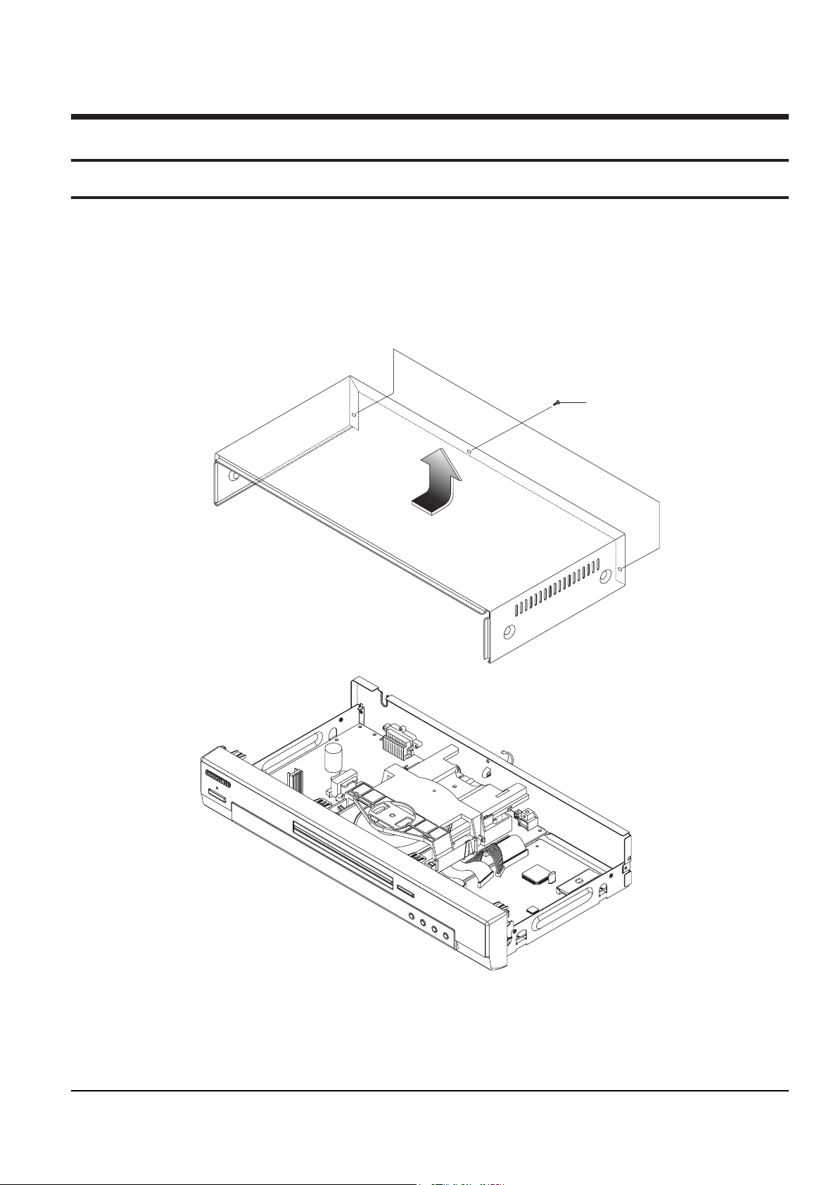
2-1-1 Top Cabinet Removal
1) Remove 3 Screws Πon the back Top Cabinet.
2) Lift up the Top Cabinet in direction of arrow.
Π3 SCREWS
Fig. 2-1 Top Cabinet Removal
Note : Reassembly in reverse order.
Page 2
2-2
Samsung Electronics
Disassembly and Reaasembly
2-1-2 Door-Tray Removal
1) Supply power and open Tray Œ.
2) Disassemble the Door-Tray ´ in direction of arrow “A”.
3) Close Tray Πand power off.
Note : If Tray Œ doesn’t open, insert a Screw driver ¨ into the Emergency hole ˇ (as shown in detailed draw-
ing) and then push it in the direction of arrow “B”. Open Tray manually.
<Side View>
ˇ EMERGENCY HOLE
¨ SCREW DRIVER
"B"
ΠTRAY
´ DOOR-TRAY
"A"
Fig. 2-2 Door-Tray Removal
Page 3
Disassembly and Reaasembly
Samsung Electronics
2-3
ΠKNOB-VOLUME
ˆ 2 HOOKS
´ 2 HOOKS
Ø ASS'Y FRONT-CABINET
’ KEY PCB
” 5 SCREWS
∏ KNOB-JOG
¨ 1 HOOK
ˇ 1 HOOK
Fig. 2-3 Ass’y Front-Cabinet Removal (DVD-S124/S126/S126G/S127/S128/S223/S224/SS227/S228/S1515)
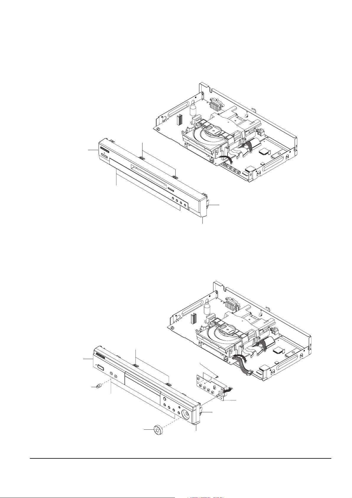
2-1-3 Ass’y Front-Cabinet Removal
<DVD-S124/S126/S126G/S127/S128/S223/S224/S227/S228/S1515>
1) Release 6 Hooks Œ, ´, ˇ, ¨ and remove Ass’y Front-Cabinet ˆ.
<DVD-S323/S324/S327/S423/S424/S427>
1) Remove Knob-Volume Œ.
2) Release 6 Hooks ´, ˇ, ¨, ˆ and remove Ass’y Front-Cabinet Ø.
3) Remove Knob-Jog ∏, 5 Screws ”, and Key PCB ’.
Fig. 2-4 Ass’y Front-Cabinet Removal (DVD-S323/S324/S327/S423/S424/S427)
¨ 2 HOOKS
Π2 HOOKS
ˆ ASS'Y FRONT-CABINET
ˇ 1 HOOK
´ 1 HOOK
Page 4
2-4
Samsung Electronics
Disassembly and Reaasembly
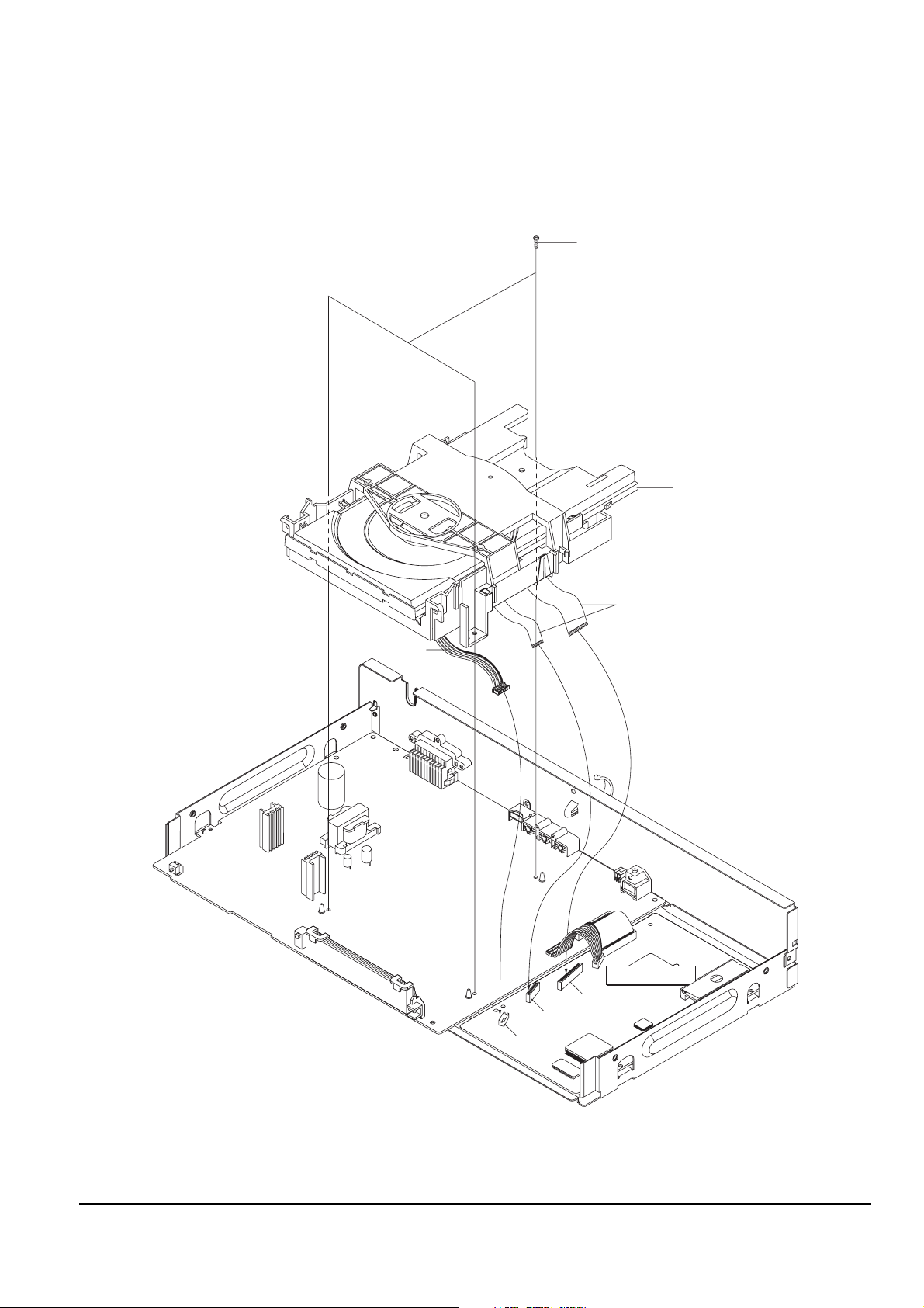
DECK-ASS'Y
Π3 SCREWS
FLAT-CABLE
CONNECT-WIRE
DCN1
DCN2
DCN3
MAIN PCB
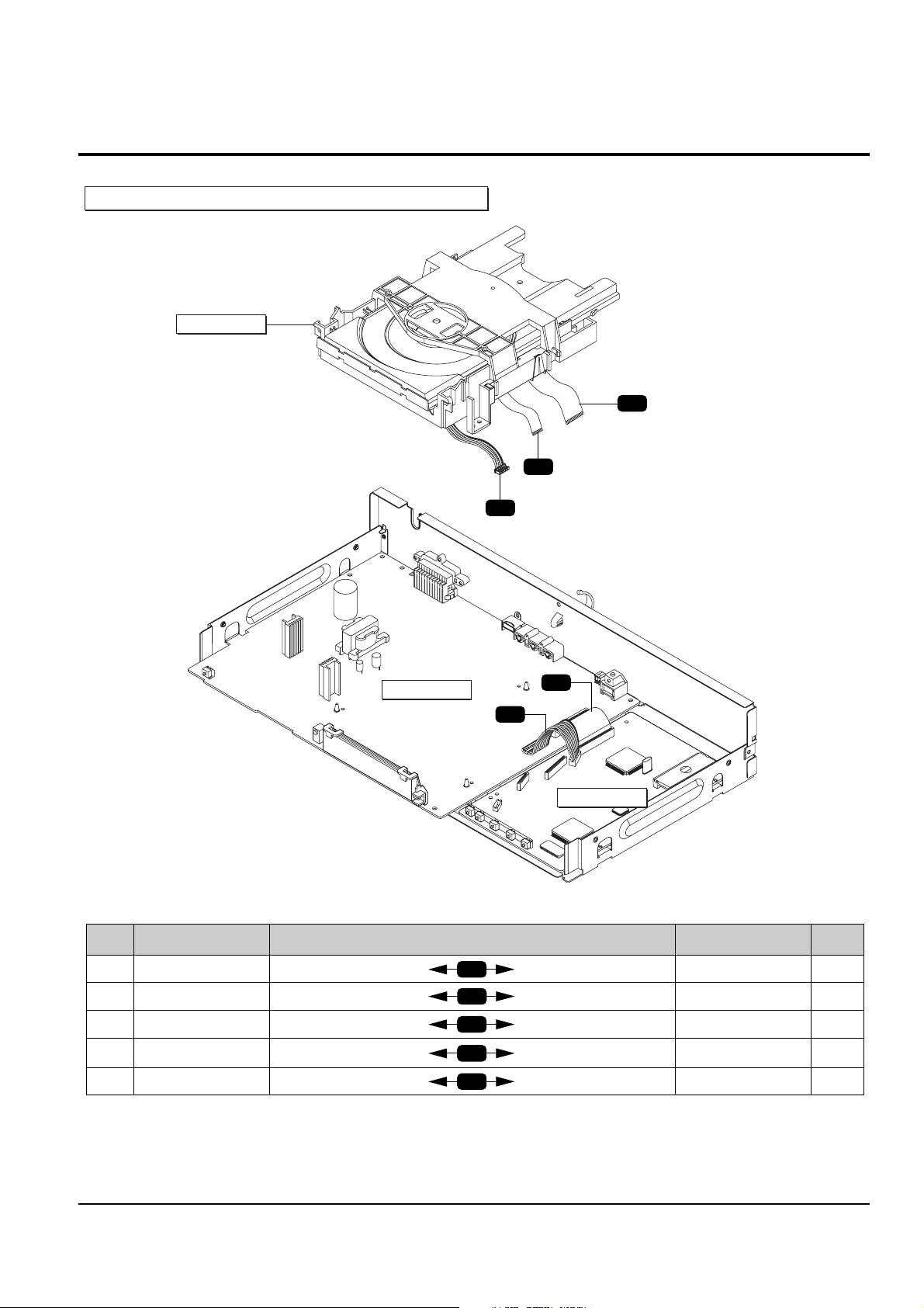
2-1-4 Ass’y Deck Removal
1) Disconnect Flat-Cable,Connect-Wire from DCN1, DCN2 and DCN3 on Main PCB.
2) Remove 3 Screws Œ from the Ass’y Deck and lift it up.
Fig. 2-5 Ass’y Deck Removal
Page 5
Disassembly and Reaasembly
Samsung Electronics
2-5
´ 2 SCREWS
ˇ JACK PCB
ˆ MAIN PCB
¨ 4 SCREWS
Π2 SCREWS
1 SCREW
1 SCART JACK
Fig. 2-6 Main PCB, Jack PCB Removal
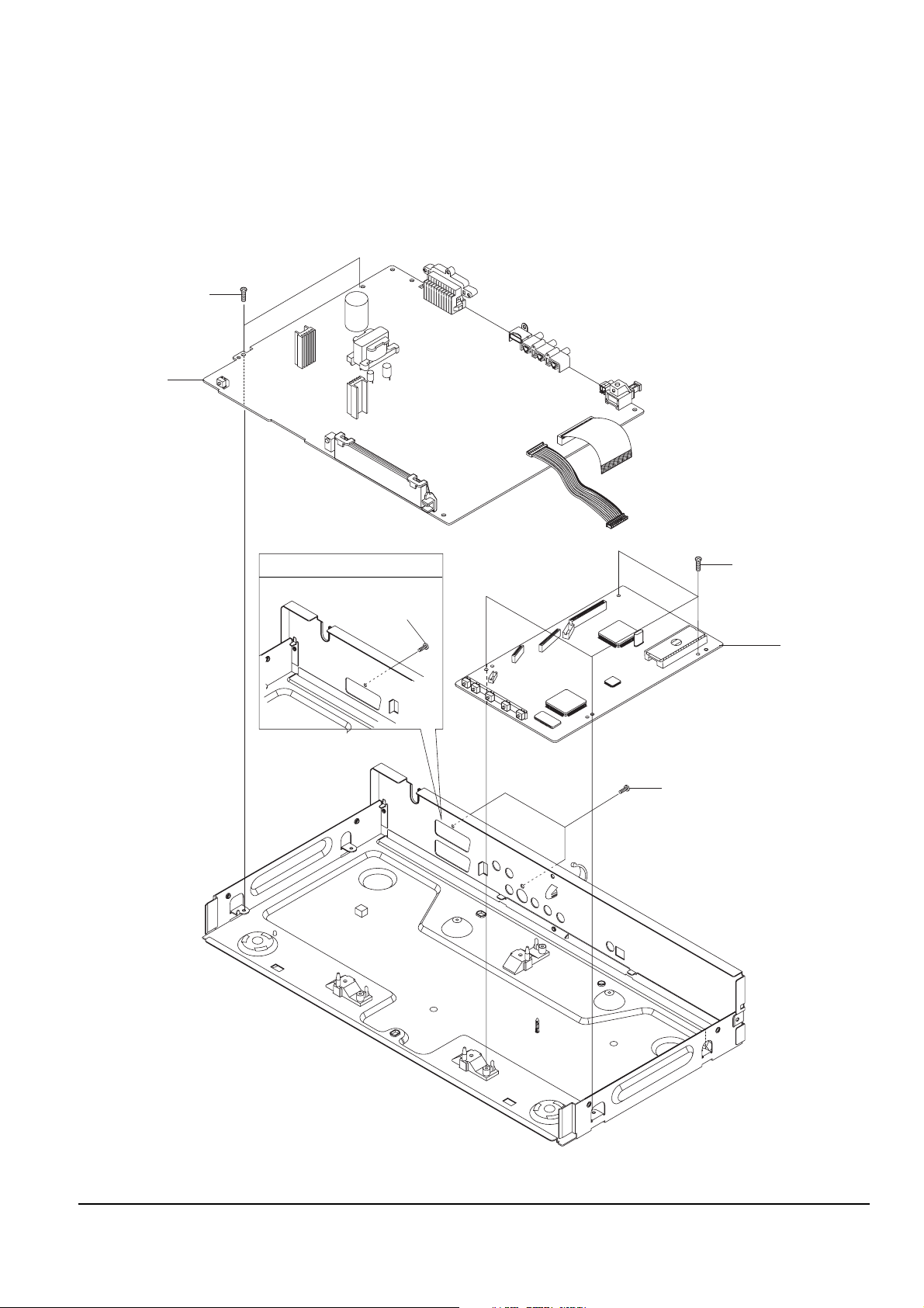
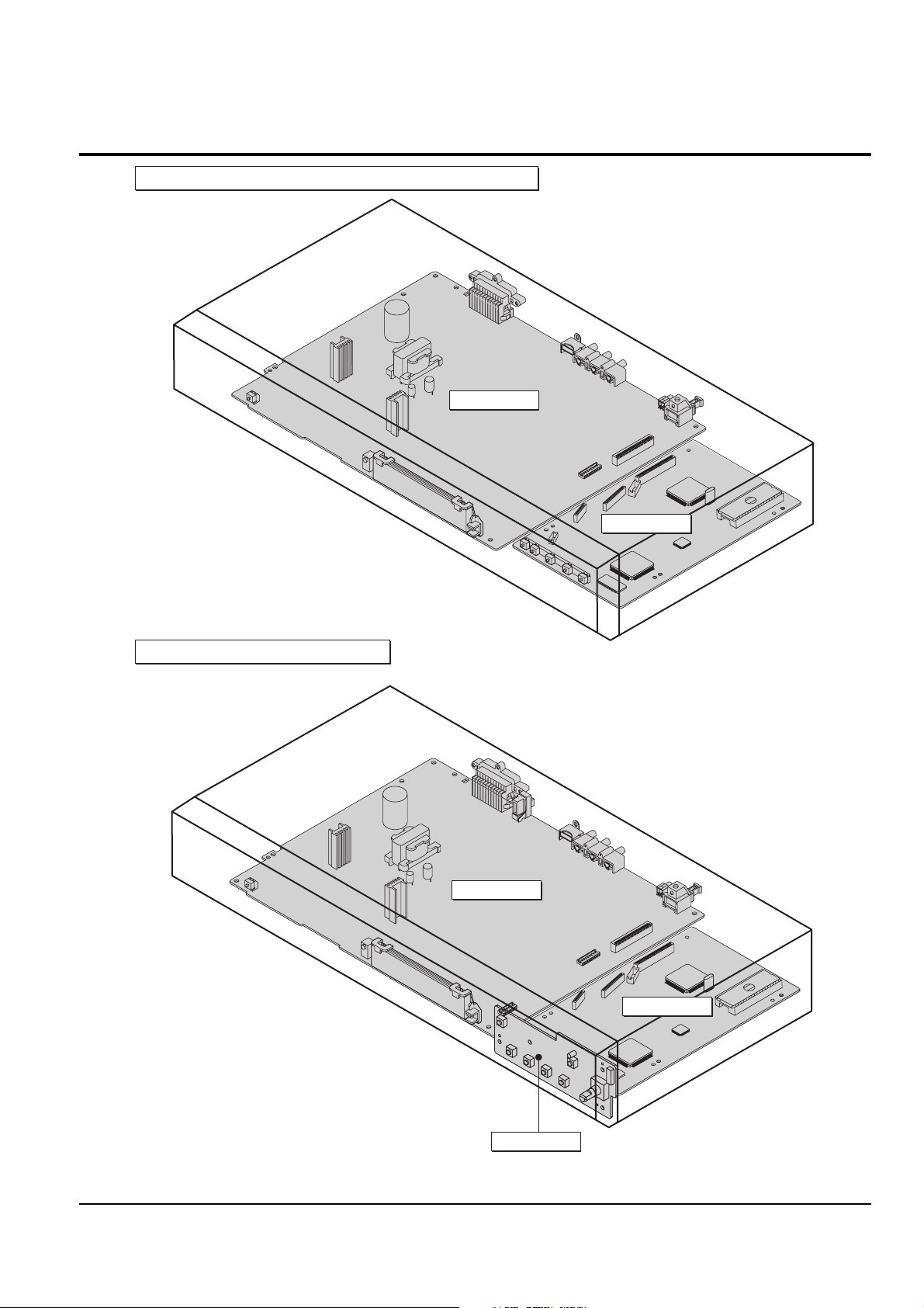
2-1-5 Main PCB, Jack PCB Removal
1) Remove 2 Screws Œ. (1 Scart Jack ; 1 Screw)
2) Remove 2 Screws ´ and lift up the Jack PCB ˇ.
3) Remove 4 Screws ¨ and lift up the Main PCB ˆ.
Page 6
2-6
Samsung Electronics
Disassembly and Reaasembly
DVD-S124/S126/S126G/S127/S128/S223/S224/S227/S228/S1515
DVD-S323/S324/S327/S423/S424/S427
JACK PCB
MAIN PCB
JACK PCB
MAIN PCB
KEY PCB
2-2 PCB Location
Fig. 2-7 PCB Location
Page 7
Disassembly and Reaasembly
Samsung Electronics
2-7
NO. CONNECTOR NO. DIRECTION CONNECTOR NO. NO.
Œ FLAT-CABLE DECK ASS'Y MAIN PCB DCN1 ´
ˇ FLAT-CABLE DECK ASS'Y MAIN PCB DCN2 ¨
ˆ
CONNECT-WIRE
(HCN1) HOUSING PCB MAIN PCB DCN3 Ø
∏ CN8 MAIN PCB JACK PCB CN1 ”
’ PCN1 MAIN PCB JACK PCB PCNS1 ˝
CT1
CT2
CT3
CT4
CT5
Œ
ˇ
ˆ
CT1
CT3
CT2
DECK-ASS'Y
JACK PCB
MAIN PCB
´
¨
Ø
∏
’
˝
”
CT4
CT5
DVD-S124/S126/S126G/S127/S128/S223/S224/S227/S228/S1515
2-3 Connector Diagram
Fig. 2-8 Connector Diagram
Page 8

2-8
Samsung Electronics
Disassembly and Reaasembly
NO. CONNECTOR NO. DIRECTION CONNECTOR NO. NO.
Œ FLAT-CABLE DECK ASS'Y MAIN PCB DCN1 ´
ˇ FLAT-CABLE DECK ASS'Y MAIN PCB DCN2 ¨
ˆ
CONNECT-WIRE
(HCN1) HOUSING PCB MAIN PCB DCN3 Ø
∏ CN8 MAIN PCB JACK PCB CN1 ”
’ PCN1 MAIN PCB JACK PCB PCNS1 ˝
Ô CN3 JACK PCB KEY PCB KCN1
CT1
CT2
CT3
CT4
CT5
CT5
Œ
ˇ
ˆ
CT1
CT3
CT2
DECK-ASS'Y
KEY PCB
CT6
JACK PCB
MAIN PCB
´
¨
Ø
∏
’
˝
Ô
”
CT4
CT5
DVD-S323/S324/S327/S423/S424/S427
Fig. 2-9 Connector Diagram
Page 9
Disassembly and Reaasembly
Samsung Electronics
2-9
2-4 Deck
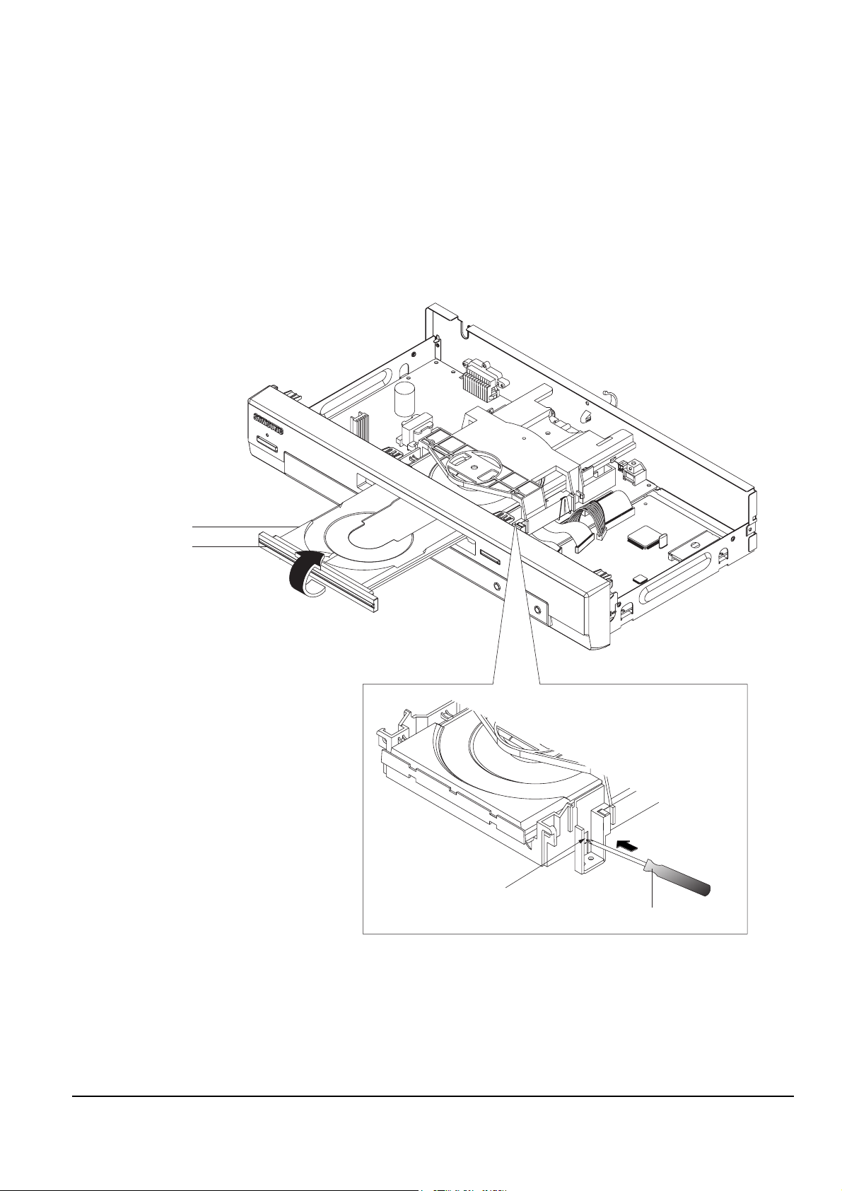
2-4-1 Tray Disc Removal
1) Insert a Screw Driver Œ into Emergency Hole ´ and push the Slider Housing ˇ in the direction arrow “A”.
2) When the Tray Disc ¨ comes out a little, pull it in the direction arrow “B” by hand.
3) Pull the Tray Disc ¨ to disassemble , while simultaneously pushing 2 Stoppers ˆ (left, right) in the direction
arrow “C”, “D”.
Fig. 2-10 Tray Disc Removal
"A"
ΠSCREW DRIVER
´ EMERGENCY HOLE
ˇ SLIDER HOUSING
¨ TRAY DISC
"B"
"C"
ˆ STOPPER
ˆ STOPPER
"D"
Page 10

2-10
Samsung Electronics
Disassembly and Reaasembly
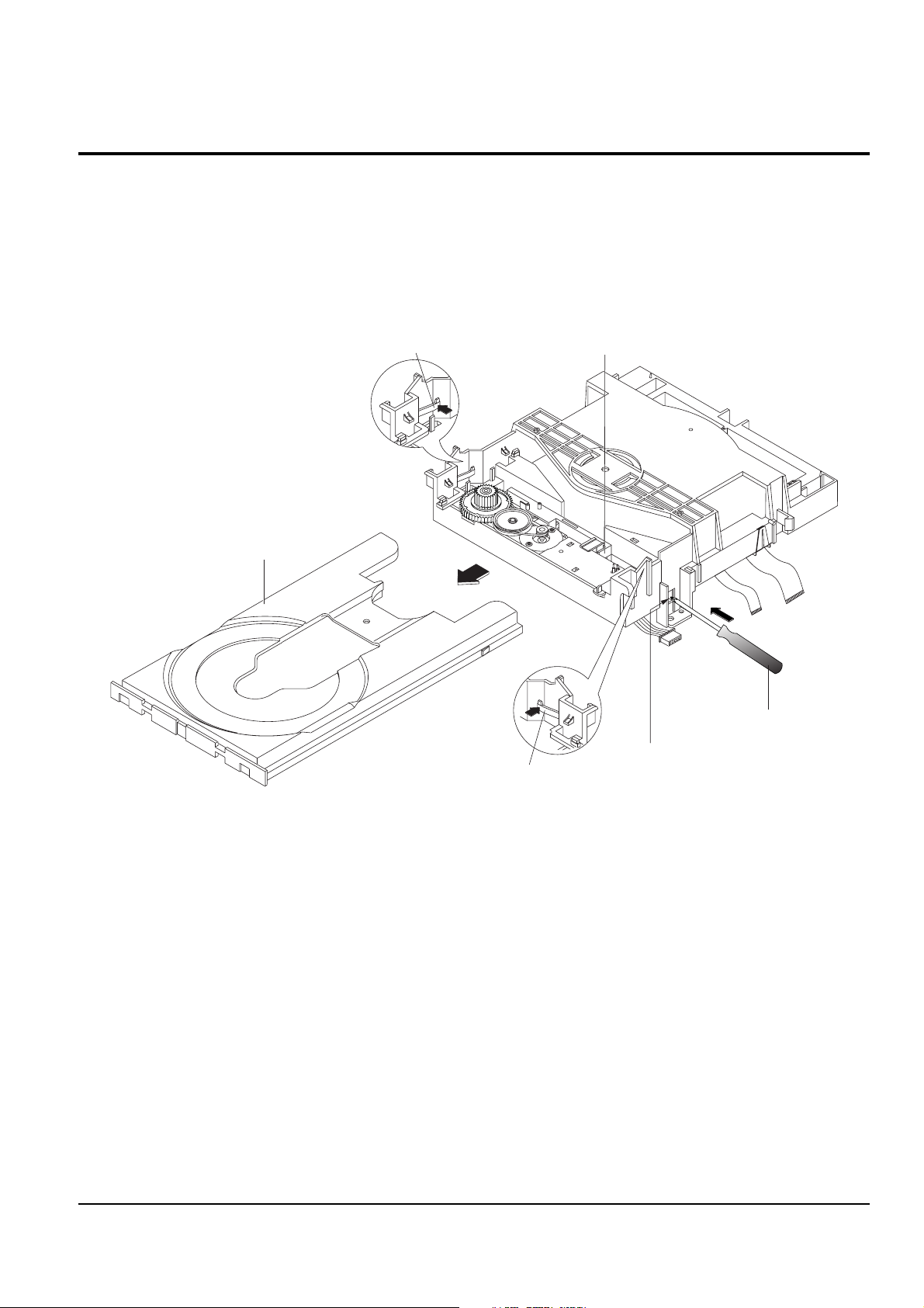
2-4-2 Assy P/U Deck Removal
1) Disconnect DCN2 Œ, DCN3 ´.
2) Lift down the Assy P/U Deck ˇ while simultaneously pushing 2 Hooks ¨, ˆ in the direction of arrow
“A”, “B”.
Fig. 2-11 Assy P/U Deck Removal
ΠDCN2
ˆ HOOK
¨ HOOK
´ DCN3
ˇ ASSY- P/U DECK
"A"
"B"
<Assembly Point>
SLIDER HOUSING
Page 11

Disassembly and Reaasembly
Samsung Electronics
2-11
2-4-3 Housing Ass’y Removal
1) Remove Belt Œ.
2) Push the Hook ´ in the direction arrow “A” and lift up Pulley Gear ˇ.
3) Push the Slider Housing ˆ in the direction arrow “B” and lift up the Gear Tray ¨.
4) Lift up the Slider Housing ˆ.
5) Remove the soldering Ø of 2 points (Red, Black).
6) Remove 2 Screws ∏ and lift down the Motor Load Assy ”.
7) Push the 3 Hooks ’ bottom side in the direction arrow “C” and lift up the Housing PCB ˝.
8) Push the Hooks Ô and remove Deck PCB .
Fig. 2-12 Housing Ass’y Removal
ΠBELT
ˇ PULLEY GEAR
¨ GEAR TRAY
” MOTOR LOAD ASSY
’ 3 HOOKS
˝ HOUSING PCB
Ô HOOK
Ø SOLDERING
∏ 2 SCREWS
ˆ SLIDER HOUSING
´ HOOK
"A"
"B"
<Bottom Side>
"C"
"C"
"C"
Page 12

2-12
Samsung Electronics
Disassembly and Reaasembly
2-4-4 Sub Chassis Removal
1) Remove the Soldering of Motor Feed (+, - wire) Œ.
2) Remove the 4 Screws ´.
3) Lift up the Ass’y Brkt Deck ˇ.
Fig. 2-13 Sub Chassis Removal
´ 4 SCREWS
ˇ ASSY-BRAK DECK
ΠSOLDERING OF
MOTOR FEED (+, - WIRE)
+
Page 13

Disassembly and Reaasembly
Samsung Electronics
2-13
2-4-5 Ass’y Brkt Deck Removal
1) Remove Washer Œ.
2) Remove Gear Feed B ´ , Gear Feed A ˇ.
3) Remove 2 Screws ¨.
4) Remove Shaft Pick-Up ˆ and Pick-Up Ass’y Ø.
5) Remove 1 Screw ∏.
6) Remove 2 Screws ”.
7) Remove 3 Spring Spindle ’ and Motor Spindle Ass’y ˝.
Fig. 2-14 Ass’y Brkt Deck Removal
¨ 2 SCREWS
ΠWASHER
´ GEAR FEED B
” 2 SCREWS
∏ 1 SCREW
ˆ SHAFT PICK-UP
ˇ GEAR FEED A
Ø PICK-UP ASS'Y
’ SPRING SPINDLE
˝ MOTOR SPINDLE
Page 14

2-14
Samsung Electronics
Disassembly and Reaasembly
MEMO
 Loading...