

Page 1
5. Troubleshooting
Since the inverter air conditioner is equipped with Electrical control circuits at both Indoor &
outdoor unit, the trouble shooting shall be performed according to the error mode.
Inside the controller of the outdoor unit (inverter), the large capacity of electrolytic condenser so
that it takes the time to discharge after the power off since the electrical charge re m a i n s
(the charging voltage DC 340V).
Take care of the electrical shock by contact on the charging part before the discharge after the
power off. (It takes approximately 2 minutes to discharg e ) .
5-1 Basic items for trouble shooting
1) Is the power source pro p e r ?
The power source shall be in the range of the rated voltage ± 1 0 %. If it is out of this range, it may
cause the abnormal operation.
2 ) Is the connection made between the indoor and outdoor unit?
The connection between indoor and outdoor unit shall be performed with 4 wire. (connection
cable of indoor and outdoor unit + ground wire ) .
3) The phenomena as follows are not out of ord e r.
NO Phenomena
The operation is not done.
1
2
The wind comes out but the
heating/cooling is not
performed.
3
The remote controller does
not operate.
The wind volume is not
4
adjusted.
5
The reservation does not
operate.
6
The temperature is not set.
Cause and reason
• Is the power off or the power unplugged?
• Does it stop because it is the completion time?
• Unplug and plug again the power source for 2 minutes.
• Is the filter clogged with dust or dirty?
• Is there any direct light on the outdoor unit or any obstacle against it?
• Is the selected temperature too high? Lower the selected temperature lower than the cur-
rent one (during cooling).
• Is the selected temperature too low? Raise the desired temperature than the current one?
• Is the “Fan only Mode” operation?
• Is the battery run out?
• Is the battery inserted in the wrong way(+, -)?
• Is the detection part of the indoor unit blocked?
• Does it interfered with the radio of neon sign?
• Is the operation selected among one of Auto / Dry / Turbo / Sleeping?
• The temperature setting is not required since the wind volume set automatically.
• Check again at the state of Cooling / Fan only / Heating.
• Is the current time input? The reservation can be made only when the current time is input.
• Is it on the stop condition? The reservation can not be made at the stop state. Press the
Operation / Stop button to make the reservation.
• Is the operation selected among the Dry / Turbo / Sleeping / Fan only Mode.
Since the temperature is automatically set, the temperature setting is not required.
• Check again at the cooling/heating state.
• The standard temperature ±2˚C during the automatic operation.
7
The operation lamp continues
to be flickering.
8
The immediate operation starts
without control of
remote
controller when plugged
Samsung Electronics
• Push the Operation / Stop button.
• Unplug and plug the power source.
• It is the case that the auto restart function works.
# Auto restart function is the convenient function where the operation state is memorized in
the Memory IC during the blackout and the operation restarts when the power comes back.
5-1
Page 2
5-2 The first determination method of troubled part
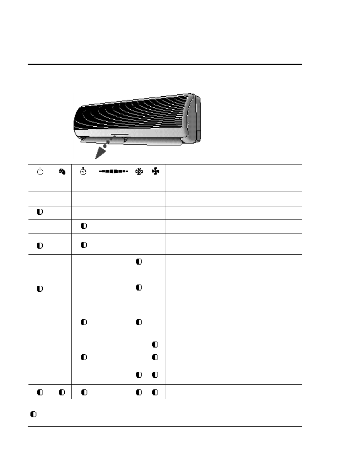
5-2-1 Error mode display of indoor unit
Opera-
tion
Defrost
X X X X X X
X X X X X
X X X X X
X X X X
Reserva-
tion
X X X X X
X X X X
X X X X
Power monitor Fan Turbo
Error mode
Operation off
Power reset
Trouble of indoor temperature sensor (open/short)
Temperature sensor trouble of the indoor heat exchanger
(open/short)
Stuck of the indoor fan motor (trouble of rotation)
Trouble of outdoor unit temperature sensor
- Discharge temperature sensor
- OLP temperature sensor of COMP top
- Defrost temperature sensor
- Outdoor temperature sensor
Communication trouble between the indoor and outdoor units
(Misconnection or circuit trouble of the indoor and outdoor
units)
X X X X X
X X X X
X X X X
L A M P
O N
(Lamp status)
: Lamp flickeringX: Lamp off
5-2
Abnormal increase of the operation current
Occurring of the inverter circuit instantaneous over current.
Abnormal increase of the COMP. Top and discharge gas temper-
ature.
Refrigerant Refill operation (test operation)
Samsung Electronics
Page 3
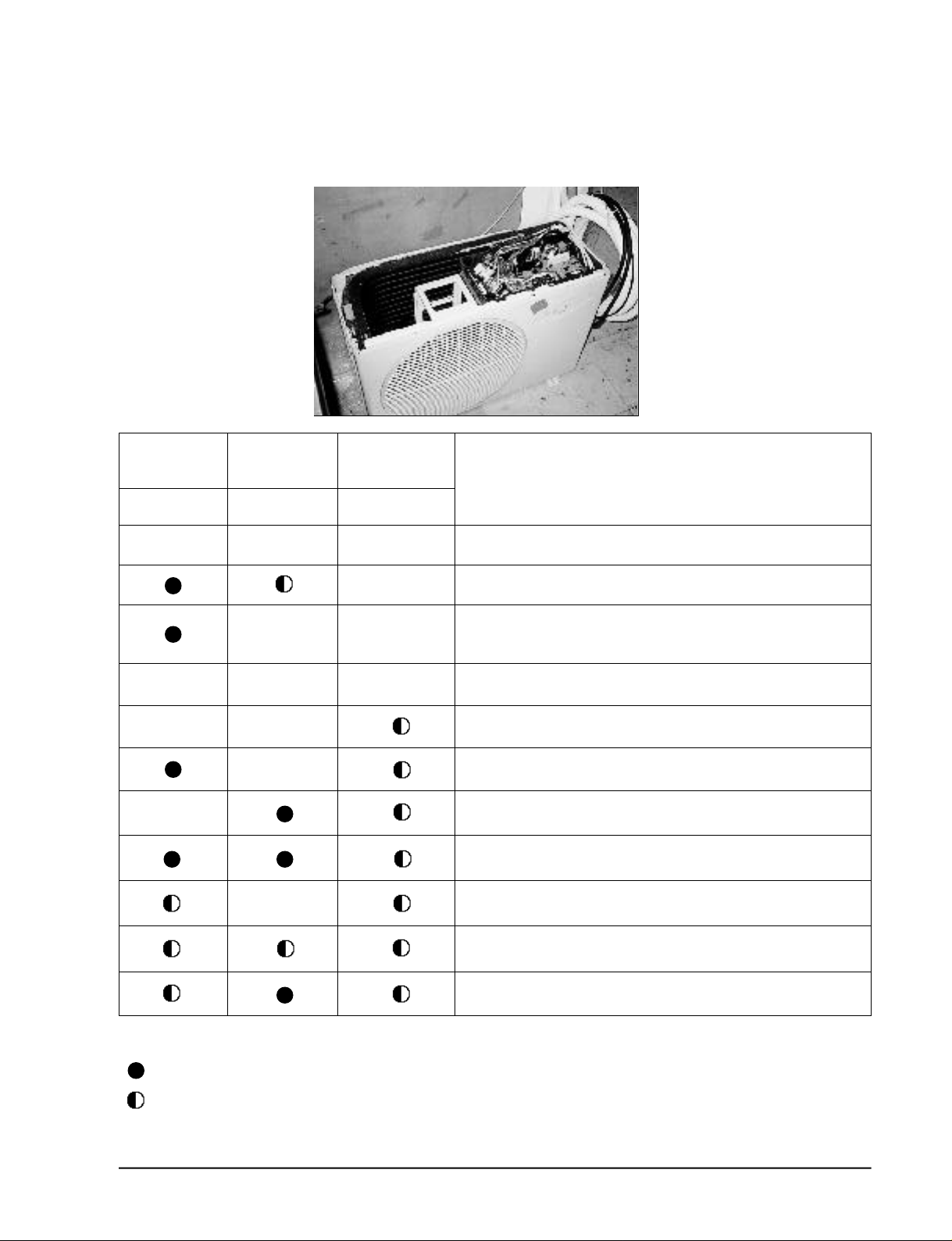
5-2-2 Error mode display of outdoor unit board
Troubleshooting
ERROR MODE
RED
X
X
X
X
GREEN
X
X
X
X
X
X
YELLOW
X
X
X
X
Operation off
Indoor-outdoor unit normal communication and operation
Abnormal communication between the indoor and outdoor unit
(miconnection or trouble of circuit between the indoor and outdor
unit)
Trouble of the control power of the outdoor(+12V)
Instantaneous over current of inverter circuit
Abnormal increase of the discharge temperature
Abnormal increase of operation current
Abnormal increase of comp top temperature.
Trouble of outdoor temperature sensor (open/short)
Trouble of the OLP temperature sensor (open/short)
(LAMP )
: LAMP ON
: LAMP FLICKERING
: LAMP OFF
X
Samsung Electronics
Trouble of outdoor Heat exchanger temperature sensor (defrost temperature sensor) (open/short)
5-3
Page 4
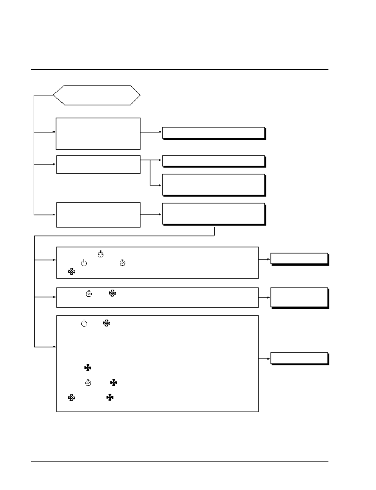
5-3 Sequence of trouble shooting for inverter aircon
OPERTION START
. The indoor unit does not work
even though the power is plugged.
. There is no sound “ting”
. The lamp is not on the display.
Check the indoor unit control board. (A)
The indoor unit does not work when
operated by the remocon.
The lamp of the indoor display lamp is
flickering and the indoor unit stops several minutes after the indoor unit starts.
Reservation lamp( ) flickering -> Check of the indoor temperature sensor (D)
Operation( ), Reservation( ) lamp flickering -> Check of the indoor heat exchanger (E)
Fan( ) lamp flickering -> Check of indoor unit fan motor (F)
Reservation( ), Fan( ) lamp flickering -> Check the lines of the indoor and outdoor
Operation( ), Fan ( ) lamp flickering -> Check of the outdoor unit temperature sensor
: Discharge temperature sensor (H)
: Comp top OLP temperature sensor (I)
: Defrost temperature sensor (J)
: Outdoor temperature sensor (K)
Turbo lamp( ) flickering -> Check of the abnormal increase protection
of the operation Current (L)
Reservation( ), Turbo( ) lamp -> Check of the instantaneous over-current protection
flickering mode of inverter circuit (M)
Fan( ), Turbo lamp( ) flickering -> Check the abnormal increase of the comp top and
discharge gas temperature protection mode.(N)
Checking the Remocon. (B)
Check the control board and the display
board of indoor unit.(C)
Check the error mode by confirming the
lamp flickering of indoor unit display.(D~N)
communication (G)
Check the indoor unit
Check of the
Communication line
Check of the Outdoor unit
5-4
Samsung Electronics
Page 5
Troubleshooting
5-3-1 (A) Check of indoor unit control board
Unplug the power cord and plug it after 5 seconds.
Open the grille of indoor unit and press the on/off switch located inside to operate the air cond i t i o n e r.
•If the air conditioner operates, check the remocon and indoor unit display board .
•If the air conditioner does not operate, check according to the sequence of the followings:
Check sequence of indoor unit control board
Step 1 : Check whether two wires of power cord (Sky-blue, brown) are connected correctly to the
c o n t rol board .
•Sky -blue : connected to TB71
• B rown : connected to #4 terminal of RY 7 1 .
(If it is connected to #3 of RY71, the power is not supplied) Take care .
Step 2: Check whether the wire connected to the terminal block is connected correctly to the
c o n t rol board .
•Sky -blue : connected to TB72
• B rown : connected to #3 terminal of RY 7 1 .
•Black : Connected to CN75
Step 3 : Check whether the fuse (F701) on the control board is normal. (3.15 [A]/250[V])
• If the fuse is broken, replace it with the new one.
Step 4 : check the output of transformer on the control board (TN71).
• Input power AC 240V, 50 Hz—-IC 01 output: DC 12V
IC 02 output : DC 5V
5-3-2 (B)(C) Display board and remocon check of indoor unit
Check whether the connection wire of Display board is correctly connected to CN92 connector.
Check the voltage of remocon battery. - the voltage of one battery shall be higher than about 1.4
V, and then the remocon operates normally.
Check whether the neon sign is on and the 3 wave long fluorescent lamp is on around the
indoor unit. - After putting all the lamps of the indoor out and then operates it by remocon. If it
operates with the remocon, it is the abnormality due to the interference from the lights of lamps.
( A i rcon unit is normal).
5-3-3 (D)(E) Check the indoor temperature sensor and indoor heat exchanger temperature sensor.
Take out the thermistor connected to the connector (CN41) of control board of indoor unit and
m e a s u re the resistance between two wires and if it is same as follows: it is normal but if not,
replace it.
Ambient temperature
(°C)
Resistance of
thermistor [KΩ]
15°C
14.68 12.09
20°C
25°C 30°C 35°C 40°C
10 8.31
6.94 5.83
The error of data of
within 1%.
Samsung Electronics
5-5
Page 6

Troubleshooting
5-3-4 (F) Check of indoor unit fan motor
Check whether the wire of fan motor is connected to the connector of control board (CN43,
CN73) of indoor unit.
Check whether the error mode displays after the strong revolution for approximately 15 seconds
since aircon is on.
-> In case the error mode displays after the fan motor is rotating for 15 seconds → Defect of
H A L L IC of fan motor and Control board
-> In case that the error mode displays without running of fan motor after 15 seconds. →
Operate with the pin of SSR(SS71) short of indoor unit control board and then if the fan
motor does not run, it is the fan motor defect.
If it rotates, it is the defect of control board (SS71, IC07, IC04).
5-3-5 (G) Check of communication line between the indoor unit and outdoor unit
(Communication error mode)
1 ) Check of connection
Check whether the cable wire connecting the indoor unit with outdoor unit is correctly connected to the C, N, R terminal. (If the wire is connected re v e r s e l y, the communication error occurs)
If the cable connecting the indoor unit and outdoor unit is longer than 20 M, error mode occurs
(shorten the cable length).
(Check of indoor unit)
Check whether the connection wire of the terminal block and control of indoor unit board is corre c t .
♦Sky -blue : connected to TB72
♦B rown : connected to #3 terminal of RY 7 1 .
♦Black : Connected to CN75
(Check of outdoor unit)
Check whether the connection wire of the terminal block and control board of outdoor unit is
c o r re c t .
♦Sky -blue : connected to TB1
♦B rown : Fuse terminal - connected to TB72
♦Black : Connected to CN71(Connected to the R701 line)
2 ) Check of power supply to the outdoor unit
After operation of aircon, select the turbo mode and approximately 3minutes later, check whether
the red color lamp of control board (to be seen if the top cover of outdoor unit) is on.
-> If the red lamp (LED 3) is not on, check the power part of control board of outdoor unit.
♦Check the connection of re a c t o r, polarity of C-ELEC (2200µF/400V) and connection of two diode
- bridge.
-> If the red lamp (LED3) is on and green lamp is flickering, it is normal.
5-6
Samsung Electronics
Page 7
Troubleshooting
5-3-6 (H)(I) Check of discharge temperature sensor and comp top OLP temperature sensor.
Connector of outdoor unit control board
(PIN#3,4 of CN41 - discharge temperature sensor)
Pin1, 2 - Take out the thermistor connected to comp top OLP t e m p e r a t u re sensor and measure
the resistance between two wires and if it is same as follows, it is normal but if not, re p l a c e .
Ambient temperature
(°C)
Resistance of ther-
mistor [KΩ]
0°C
553
10°C
362
20°C
242
30°C 40°C
166 165
50°C
The error of data of
82
5-3-7 (J)(K) Check the defrost temperature sensor and outdoor temperature sensor
Connector of outdoor unit control board
(PIN#1,2 of CN41 - outdoor temperature sensor)
Pin3, 4 - Take out the thermistor connected to defrost temperature sensor and measure the re s i stance between two wires and if it is same as follows, it is normal but if not, replace it.
Ambient temperature
(°C)
Resistance of ther-
mistor [KΩ]
15°C
14.68 12.09 10 8.31 6.94 5.83
20°C 25°C 30°C 35°C 40°C
The error of data of
5-3-8 (L) Check of operation current abnormal rise mode
The operation abnormal current mode is the protection control for the safe operation by detecting the operation current of inverter aircon by the current sensor on the control board .
If the operation current abnormal rise occurs,
♦The ventilation is not good because the outdoor unit is installed wrong (the ambient tempera-
t u re is higher than 50 °C)
-> Reinstall the outdoor unit so that the good ventilation can be made.
♦If the Refrigerant is overc h a rged.
-> Check the amount of Refrigerant.
♦If the comp is locked.
-> Replace the comp.
♦If the comp is operating without the revolution of fan motor.
-> Check the fan motor connector, replace the fan motor.
♦If the protection cover is operating with bending to the outdoor.
-> Take out the protection cover.
♦If two outdoor units are operating face to face. (the bad ventilation is made)
-> Reinstall the outdoor unit for the good ventilation.
♦The air circulation is bad due to the attachment of falling leaves
-> Take away the leaves for the good ventilation.
within 5%.
within 1%.
Check the elements of current sensor block of the outdoor control board .
♦R801 — 1 KΩ
♦R802 — 1.5 KΩ
♦R803 — 15 KΩ
Samsung Electronics
5-7
Page 8

Troubleshooting
5-3-9 (M) Check of instantaneous over-current protection of inverter circuit.
Inverter instantaneous over- c u r rent protection mode is the mode to be actuated in order to
p revent the damage of elements from the peak current of inverter circuit elements.
In case that the inverter circuit instantaneous over- c u r rent protection mode actuates.
(condition of installation)
♦The ventilation is not good because the outdoor unit is installed wrong (the ambient tempera-
t u re is higher than 50 (°C) )
-> Reinstall the outdoor unit so that the good ventilation can be made.
♦In case that the operation is made with the cover bent of the outdoor unit.
-> Take out the cover.
♦If two outdoor units are operating face to face, (the bad ventilation is made)
-> Reinstall the outdoor unit for the good ventilation.
♦The air circulation is bad due to the attachment of falling leaves.
-> Take away the leaves for the good ventilation.
♦If the Refrigerant is overc h a rged.
-> Check the amount of Refrigerant.
(Unit defect)
♦If the comp is locked.
-> Replace the comp.
♦If the comp is operating without the revolution of fan motor.
-> Check the fan motor connector and replace the fan motor.
♦In case the parts of the control board is damaged.
-> Replace simultaneously the inverter control board and the power TR.
If only the inverter control board is replaced with the state the power TR. is damaged, the control board is damaged again.
(Same as for the vice versa of the above.)
5-3-10 (N) Check of the comp Top OLP and discharge gas temperature abnormal rise.
If the comp top temperature and the discharge gas temperature rises higher than a certain level,
it protects the circ u i t .
If the comp top OLP t e m p e r a t u re and the discharge gas temperature rises abnormally,
(Condition of installation)
♦The ventilation is not good because the outdoor unit is installed wrong (the ambient tempera-
t u re is higher than 50 (°C) )
-> Reinstall the outdoor unit so that the good ventilation can be made.
♦In case that the operation is made with the cover bent of the outdoor unit.
-> Take out the cover.
♦If two outdoor units are operating face to face, (the bad ventilation is made)
-> Reinstall the outdoor unit for the good ventilation.
♦The air circulation is bad due to the attachment of falling leaves
-> Take away the leaves for the good ventilation.
♦If the refrigerant is insufficient.
-> Fill up the amount of re f r i g e r a n t .
5-8
Samsung Electronics
Page 9
(Unit defect)
♦If the comp is locked.
-> Replace the comp.
♦If the comp is operating without the revolution of fan motor
-> Take out the protection cover.(cooling mode)
-> Check the fan motor connector and replace the fan motor.
5-4 Check method of major parts
Troubleshooting
NO
Parts Check method
1
Inverter controller
(outdoor unit con-
troller)
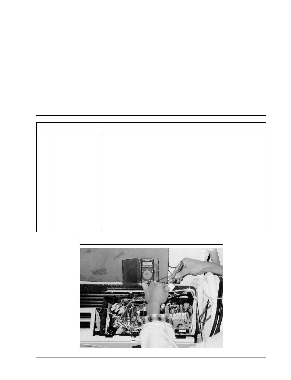
1. Open the top cover of outdoor unit.
2. Separate the connector (3P) connecting the comp from the outdoor unit controller. (wire
to wire connector).
3. Operate the aircon in the turbo mode. (operate the outdoor 3 minutes after)
4. Measure the voltage across the terminals of comp connector (3p) from the power TR
module if the outdoor fan is running.
( If normal)
AC voltage of each terminal is similar.
•Phase U-V : AC voltage is measured (80V- 190V)
•Phase V-W : AC voltage is measured (80V- 190V)
•Phase W-U : AC voltage is measured (80V- 190V) (at AC220V)
(If abnormal)
•The AC voltage is not measured from any one(or two) of Phase U-V, V-W or W-U.
- Check the power TR module.
- Check the other parts
MEASURING METHOD of INVERTER CONTROLLER
Samsung Electronics
5-9
Page 10
Troubleshooting
NO
Parts Check method
2
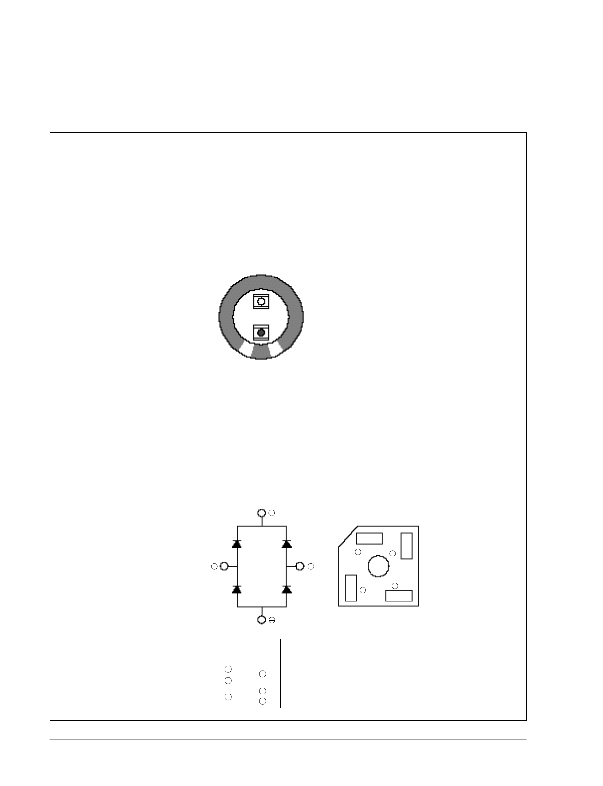
Electrolytic condenser
(film condenser)
1. Put off the power.
2. Discharge all of condenser completely.
3. Take the lead out of (±) side completely.
4. Check whether any part of the safety hole is damaged from condenser.
5. Check whether the container is expand or damaged.
6. Check whether the analytical is out.
7. Check whether the normal discharge characteristics are obtained during the energized
check of tester.
+
2200µF/400V
-
If it is good, the needle rises but falls down slowly. The needle comes back after the polarity reversed.
3
Bridge Diode block
1. Put off the power.
2. Discharge all of condenser completely.
3. Remove 4 terminals connected to the diode block.
4. Check whether the normal discharge characteristics are obtained during the energized
check of tester.
~
~
~
~
Tester rod If it is good one,
(-) (+) the resistance
~
~
-
+
~
∞
~
•When the tester rod is
reversed : 10-20 ohm.
5-10
Samsung Electronics
Page 11
Troubleshooting
NO
Parts Check method
4
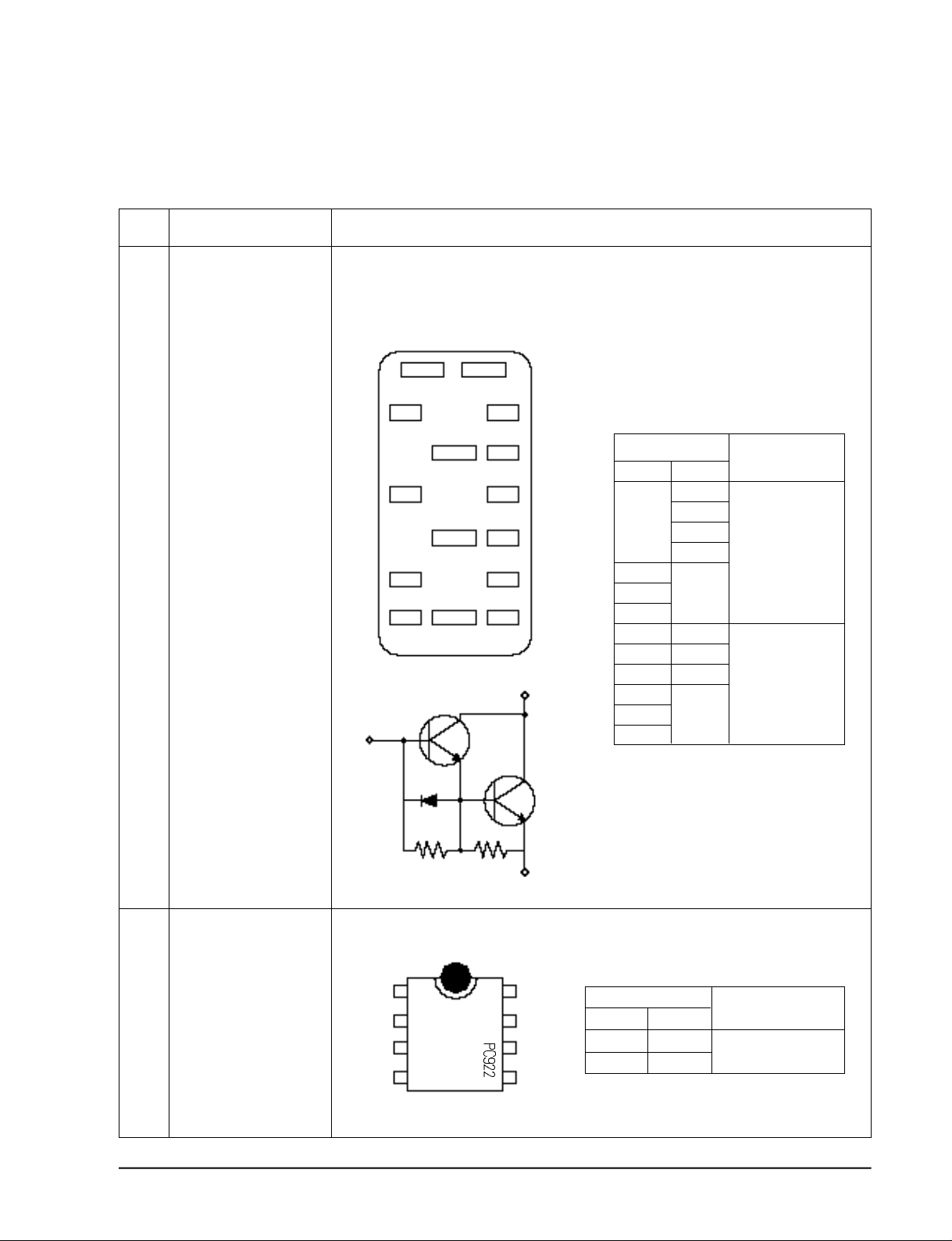
Power TR module
1. Put the power off completely.
2. Discharge all of condenser completely.
3. Separate the transistor module from the inverter body.
4. Check the leak current between C and E and B by tester for 6 transistors
- +
BX
BY
BZ
Base(B)
U
V
BU
EU
BV
EV
BW
EWWEC
Collector(C)
Tester rod
( + )
-
U
V
W
BU
BV
BW
BX
BY
BX
( - )
+
U
V
W
+
EU
EV
EW
EC
If it is good one
10KΩ ~ 500KΩ
400Ω ~ 500Ω
resistance
5
Samsung Electronics
PC 922
(IC3~IC8)
Emitter(E)
5. If the power transistor module is defective, check the parts of (PC3~PC8) of control board
out of inverter controller.
1
2
3
4
8
7
6
5
Tester rod If it is good one
( + ) ( - )
6
7
7
6
resistance
∞
If the resistance between the 6 and 7 is a couple of Kohm, it is defective.
5-11
 Loading...