How it Works
Log In / Sign Up
Buy Points
How it Works
FAQ
Contact Us
Questions and Suggestions
Users
Samsung
Loading...
A
AQV07PSBN
AQV09A1
AQV09A2
AQV09A5
AQV09A6
AQV09ABA
AQV09ABAN
5
AQV09ABANSER
AQV09ABAX
3
AQV09ABBN
2
AQV09ABBX
2
AQV09ACME
7
AQV09ADME
7
AQV09AS
AQV09ASAN
4
AQV09ASAX
2
AQV09AW
2
AQV09AWA
AQV09AWAN
AQV09AWANSER
AQV09AWAX
5
AQV09AWB
AQV09AWBN
5
AQV09AWBX
2
AQV09E00
AQV09EWA
AQV09EWAN
7
AQV09EWAX
4
AQV09EWCN
3
AQV09EWCX
2
AQV09EWEX
3
AQV09F2VE
AQV09FA
2
AQV09FAN
7
AQV09FAX
6
AQV09FC
6
AQV09FCN
10
AQV09FCX
8
AQV09FKN
6
AQV09FKX
5
AQV09J
2
AQV09KBBN
7
AQV09KBBX
AQV09MSAN
5
AQV09MSAX
6
AQV09MWAN
5
AQV09MWAX
5
AQV09NS
AQV09NSA
6
AQV09NSAN
10
AQV09NSAX
9
AQV09NSB
AQV09NSBN
6
AQV09NSBX
5
AQV09NSD
AQV09NSDN
AQV09NSDX
2
AQV09PMEN
AQV09PMEX
AQV09PSBN
6
AQV09PSBX
5
AQV09PSCN
AQV09PSDN
AQV09PSDNSER
AQV09PSDX
AQV09PWAN
3
AQV09PWAX
4
AQV09PWCN
2
AQV09PWCX
2
AQV09PWDN
AQV09UGAN
7
AQV09UGAX
3
AQV09UGEN
2
AQV09UGFN
AQV09UGFX
AQV09UW
AQV09UWAN
AQV09UWBX
AQV09UWLX
AQV09V
AQV09VBA
AQV09VBAN
6
AQV09VBC
2
AQV09VBCN
5
AQV09VBCX
3
AQV09VBEN
5
AQV09VBENXAZ
2
AQV09VBEX
5
AQV09VC
2
AQV09VSAN
AQV09VSCN
AQV09VSCX
AQV09VSDX
AQV09YWAN
11
AQV09YWAX
6
AQV09YWC
AQV09YWCN
2
AQV09YWCX
AQV10FKN
2
AQV10FKX
2
Loading...
Loading...
Nothing found
AQV09NSAX
Service Manual
93 pgs
9.28 Mb
0
User Manual
26 pgs
11.1 Mb
0
Service Manual
92 pgs
17.79 Mb
0
Service Manual
100 pgs
20.41 Mb
0
Service Manual
100 pgs
22.8 Mb
0
Service Manual
67 pgs
5.05 Mb
0
User Manual [es]
26 pgs
11.1 Mb
0
User Manual [de]
26 pgs
11.1 Mb
0
User Manual [pt]
26 pgs
11.05 Mb
0
Table of contents
Loading...
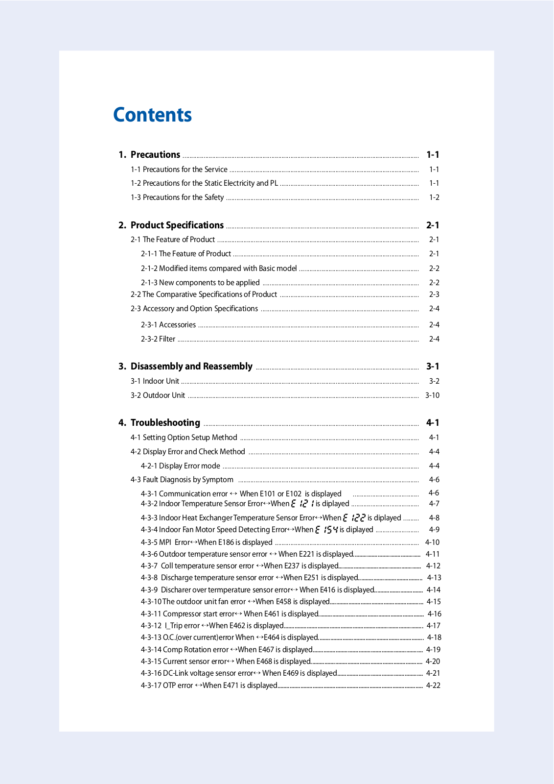
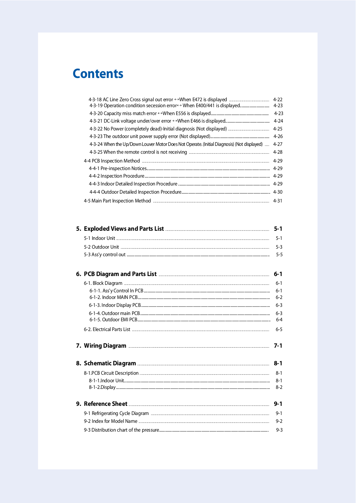
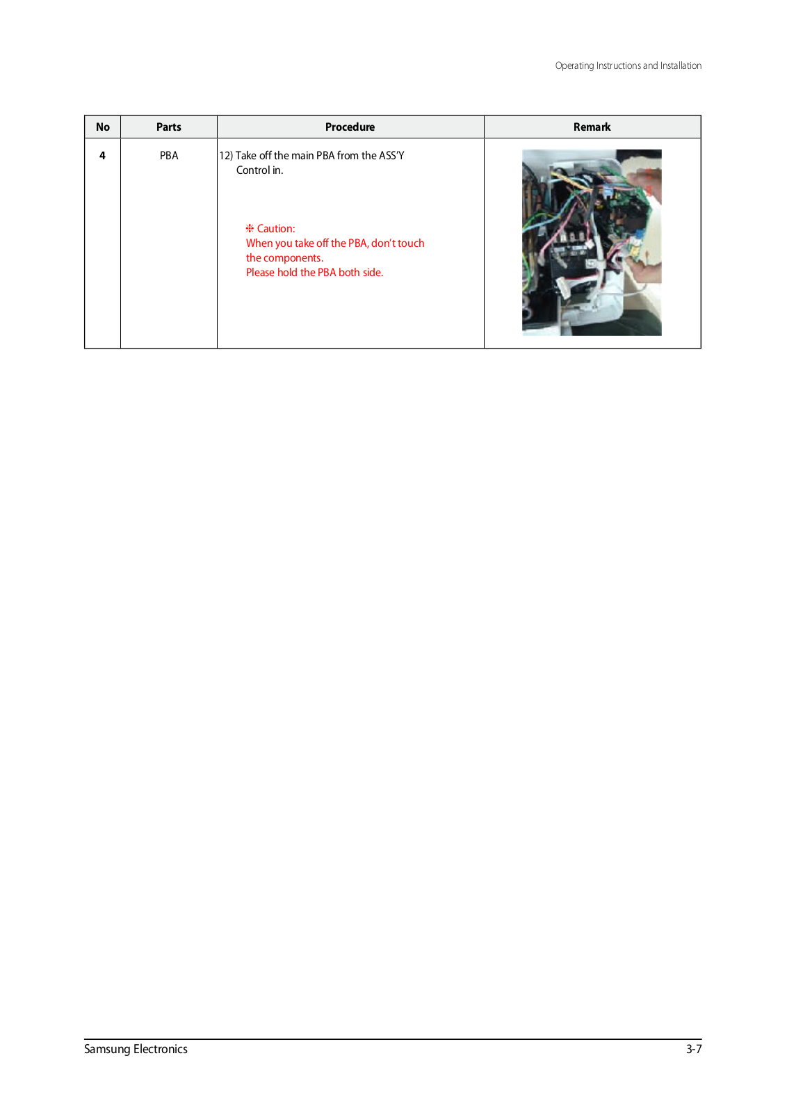
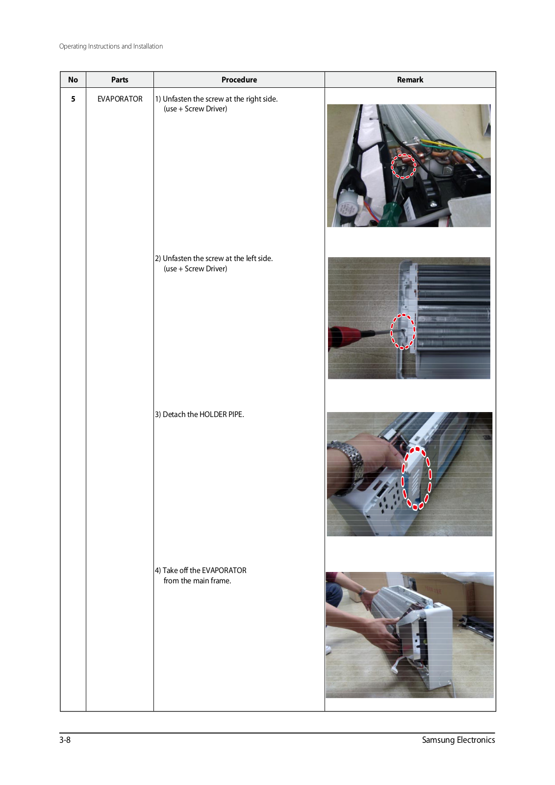
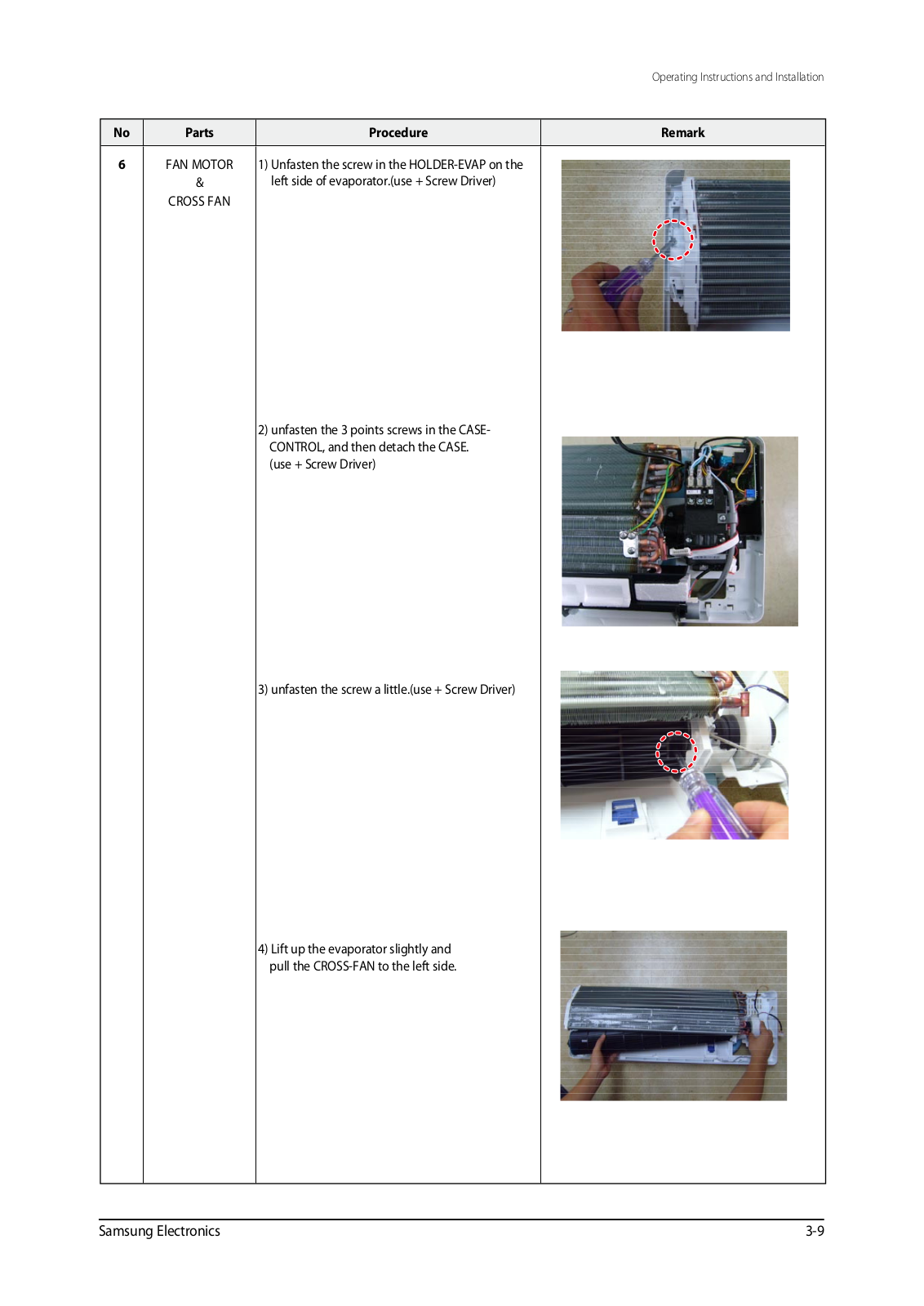
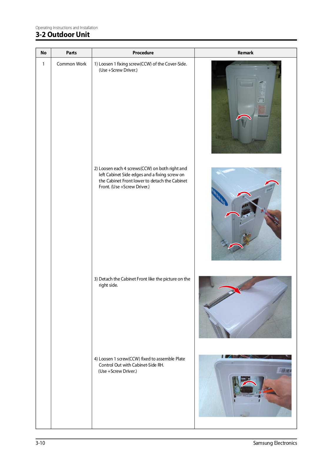
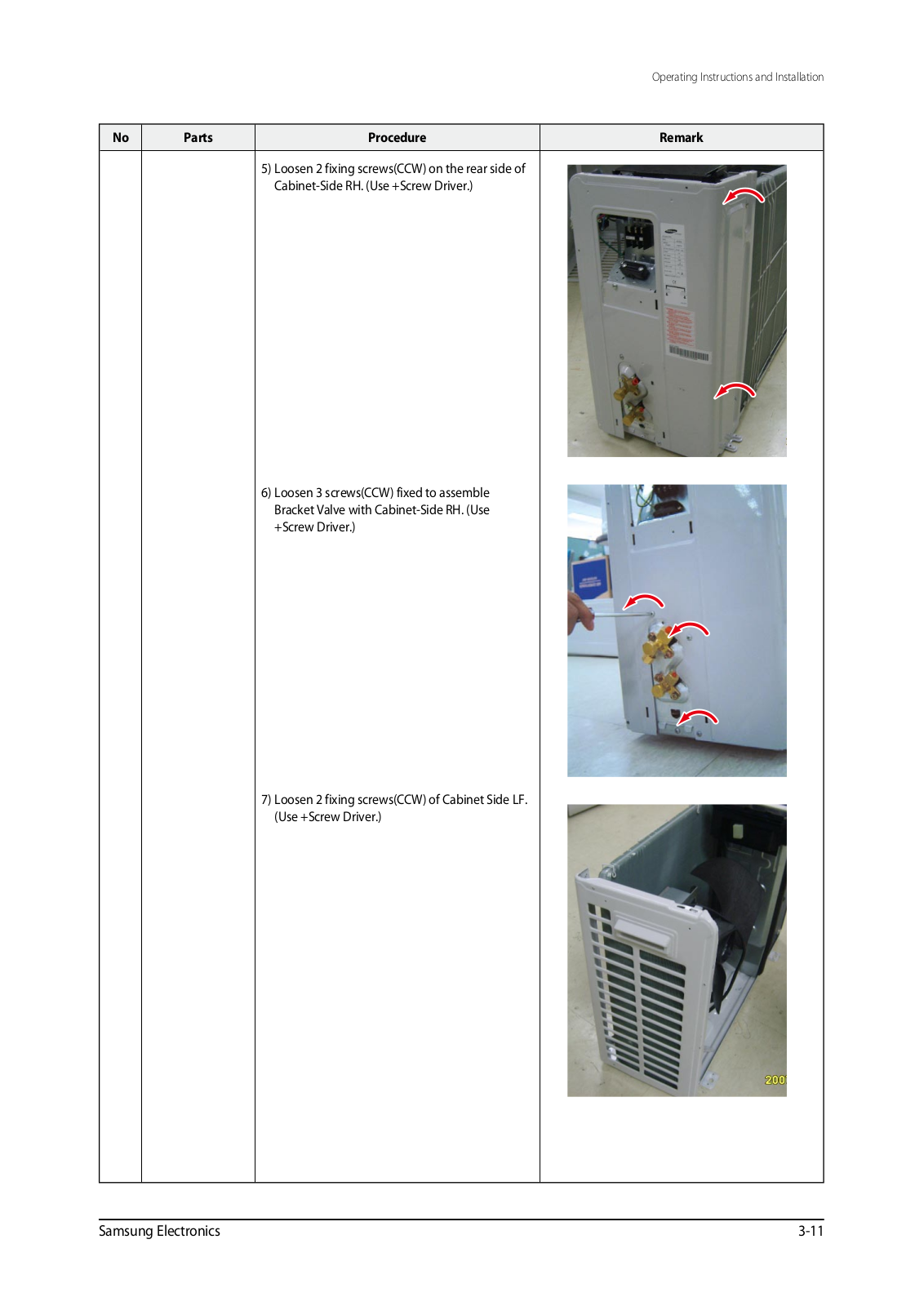
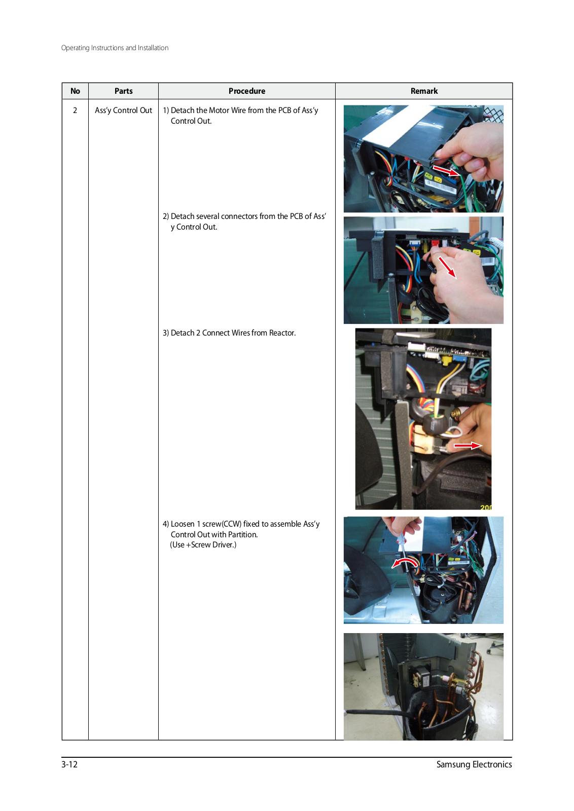
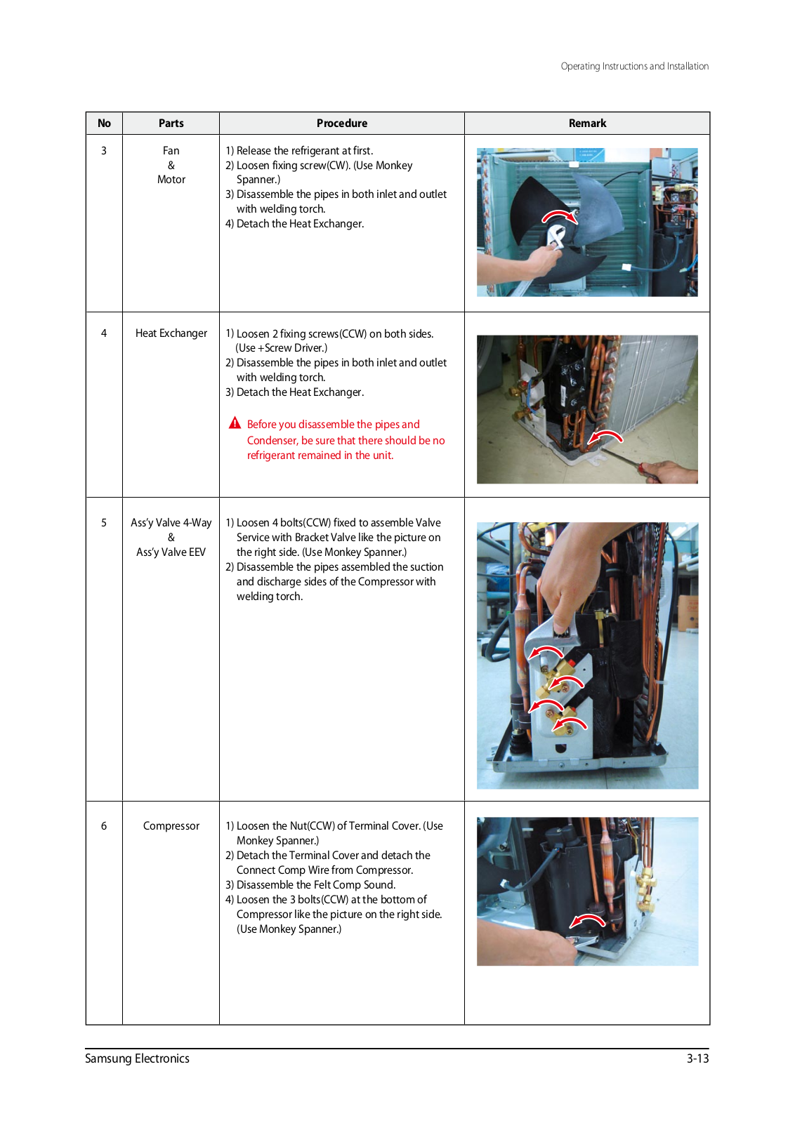
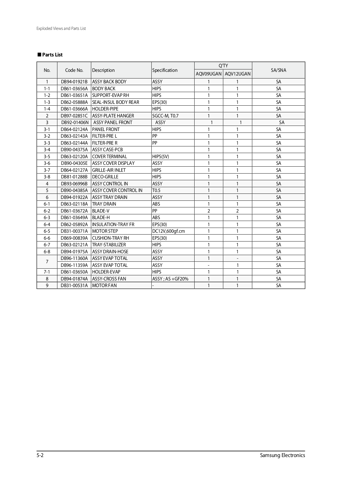
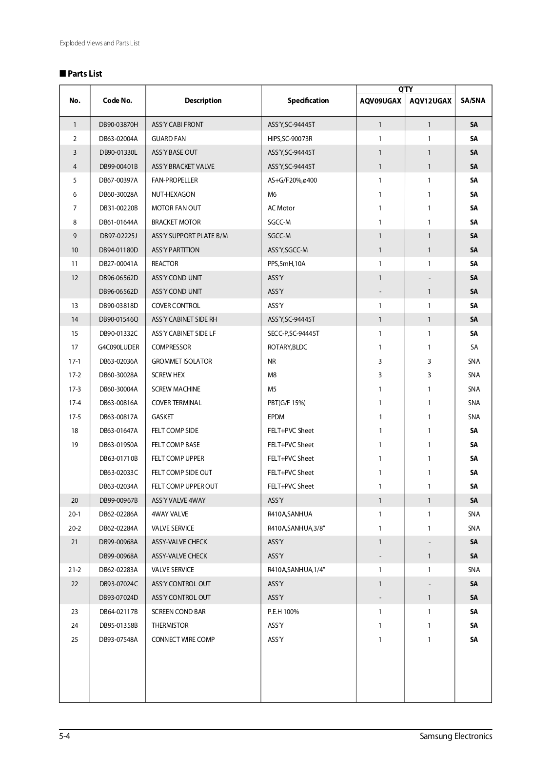
Samsung AQV12FA, AQV09NSA, AQV09FC, AQV12NSA, AQV12FC Service Manual
...
Samsung AQV12FA, AQV09NSA, AQV09FC, AQV12NSA, AQV12FC, AQV09NSAN, AQV09NSAX, AQV09FCN, AQV09FCX, AQV12NSAN, AQV12NSAX, AQV12FCN, AQV12FCX Service Manual
Download
Loading...
+
65
hidden pages
Unhide
You need points to download manuals.
1 point = 1 manual.
You can buy points or you can get point for every manual you upload.
Buy points
Upload your manuals
 Loading...