

Samsung 80089, 80082, 80083, 80084, 80086 User Manual

V/
MICROWAVE OVEN
MODEL " 80089
80082
80084
80086
80083
Manual
1. Precaution
2. Specification
3. Operating Instructions
4. Installation
5. Disassembly and Reassembly
6. Alignment and Adjustments
7. Troubleshooting
8. Exploded Views and Part List
9. PCB Diagrams
10. Wiring Diagrams
11. Schematic Diagrams

1. Precaution ............................................................................................3
1-1 Safety precautions ................................................................................... 4
1-2 Special High Voltage Precautions ....................................................................... 5
2. Specifications ......................................................................................... $
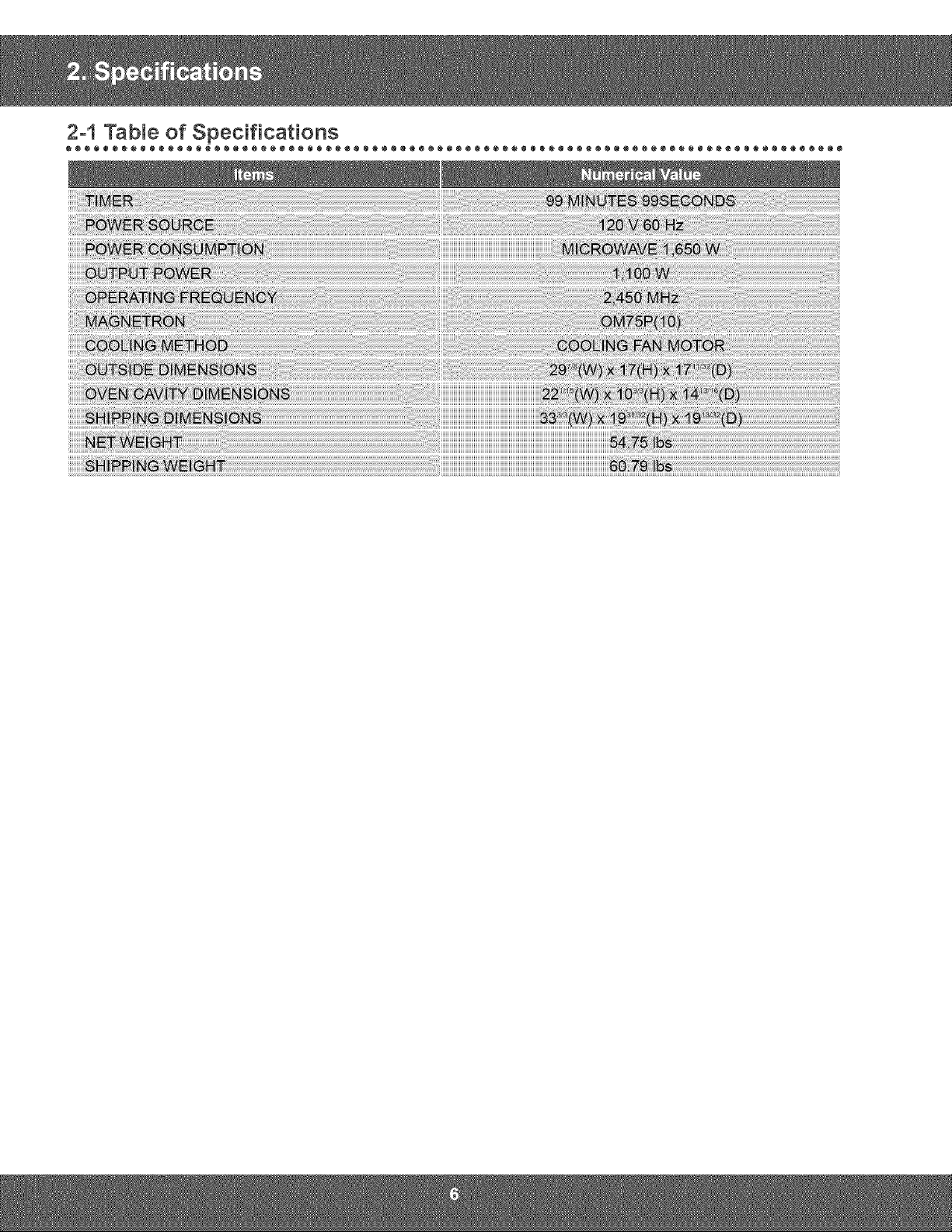
2-1 Table of Specifications ................................................................................ 6
2-2 Accessory ......................................................................................... 7
3. Operating Instructions .................................................................................. 8
3-1 Control Panel ....................................................................................... 8
3-2 Features & External Views ............................................................................ 9
4. _nstallation...........................................................................................10
5. DisassemMy and Reassembly ........................................................................... 12
5-1 Replacement of High Voltage Transformer ............................................................... 12
5-2 Replacement of Magnetron ........................................................................... 14
5-3 Replacement of Door Assembly ....................................................................... 15
5-3 Replacement of Door Assembly ....................................................................... 16
5-4 Replacement of Fuse ............................................................................... 17
5-5 Replacement of Drive Motor .......................................................................... 17
5-6 Replacement of stirrer motor .......................................................................... 18
5-7 Removal of stirrer .................................................................................. 19
5-8 Replacement of Control Circuit Board ................................................................... 20
5-9 Replacement of Cooktop lamp ........................................................................ 21
5-10 Replacement of Oven Light .......................................................................... 22
6. Alignment and Adjustments ............................................................................. 28
6-1 High Voltage Transformer ............................................................................ 23
6-2 Magnetron ........................................................................................ 23
6-3 High Voltage Capacitor .............................................................................. 23
6-4 High Voltage Diode ................................................................................. 24
6-5 Main Relay and Power Control Relay ................................................................... 24
6-6 Adjustment of Primary Switch, Door Sensing Switch and Monitor Switch........................................ 24
6-7 Vent Exhaust Blower Motor ........................................................................... 25
6-8 Thermal Cutout (TCO'S) ............................................................................. 26
6-8-1 Oven Thermal Cutout(Flame sensor) ............................................................... 26
6-8-2 Replacement of Flame Sensor.................................................................... 26
6-8-3 Hood Thermal Cutout ........................................................................... 27
6-8-4 Bottom Thermal Cutout ......................................................................... 27
6-8-5 Magnetron Thermal Cutout ...................................................................... 27
6-9 Output Power of Magnetron .......................................................................... 28
6-10 Procedure for Measurement of Microwave Energy Leakage ................................................ 29
6-11 Check for Microwave Leakage ....................................................................... 29
6-12 Note in Measurement .............................................................................. 29
6-13 Leakage Measuring Procedure ....................................................................... 29
6-13-1 Record keeping and notification after measurement .................................................. 29
6-13-2 At least once a year have the microwave energy survey meter checked for accuracy by its manufacturer ......... 29
6-14 Sensor .......................................................................................... 30
7. Troubleshooting ...................................................................................... 31
7-1 Electrical Malfunction ............................................................................... 31
7-2 Error Code List .................................................................................... 34
8. Exploded Views and Parts List .......................................................................... 38
8-1 Exploded Views .................................................................................... 35
8-2 Main Parts List..................................................................................... 37
& PCB Diagrams ........................................................................................ 82
9-1. PCB Diagrams .................................................................................... 52
9-2. PCB Diagrams .................................................................................... 53
10, Wiring Diagrams ..................................................................................... 84
10-1 Wiring Diagrams .................................................................................. 54
10-2 Wiring Diagrams .................................................................................. 55
(a) Do not operate or allow the oven to be
operated with the door open.
(b) Make the following safety checks on all
ovens to be serviced before activating the
magnetron or other microwave source,
and make repairs as necessary:
(1) Interlock operation,
(2) proper door closing,
(3) seal and sealing surfaces (arcing,
wear, and other damage),
(4) damage to or loosening of hinges and
latches,
(5) evidence of dropping or abuse.
(c) Before turning on microwave power for
any service test or inspection within the
microwave generating compartments,
check the magnetron, wave guide or
transmission line, and cavity for proper
alignment, integrity, and connections.
(d) Any defective or misadjusted components
in the interlock, monitor, door seal, and
microwave generation and transmission
systems shall be repaired, replaced, or
adjusted by procedures described in this
manual before the oven is released to the
owner.
(e) A Microwave leakage check to verify
compliance with the Federal performance
standard should be performed on each
oven prior to release to the owner.

Follow these special safety precautions. Although the microwave oven is completely safe during ordinary use,
repair work can be extremely hazardous due to possible exposure to microwave radiation, as well as potentially
lethal high voltages and currents.
1. All repairs should be done in accordance with the
procedures described in this manual. This product
complies with Federal Performance Standard 21
CFR
2. Microwave emission check should be performed to
prior to servicing if the oven is operative.
3. If the oven operates with the door open :Instruct
the user not to operate the oven and contact
the manufacturer and the center for devices and
radiological health immediately.
4. Notify the Central Service Center if the microwave
leakage exceeds 5 mW/cm2.
5. Checkall grounds.
6. Do not power the MWO from a "2-prong"AC cord.
Be sure that all of the built-in protective devices are
replaced. Restore any missing protective shields.
7. When reinstalling the chassis and its assemblies,
be sure to restore all protective devices, including:
nonmetallic control knobs and compartment covers.
8. Make sure that there are no cabinet openings
through which people --particularly children--might
insert objects and contact dangerous voltages.
Examples: Lamp hole,ventilation slots.
9. Inform the manufacturer of any oven foundto have
emission in excess of 5 mW/cm2 ,Make repairs to
bring the unit into compliance at no cost to owner
and try to determine cause. Instruct owner not to use
oven until it has been brought into compliance.
CENTRAL SERVICE CENTER
10. Service technicians should remove their watches
whilerepairing an MWO.
11. To avoidany possible radiation hazard,replace parts
in accordance with the wiring diagram. Also, use
only the exact replacements for the following parts:
Primary and secondary interlock switches, interlock
monitor switch.
12. If the fuse is blown by the Interlock Monitor Switch:
Replace all of the following at the same time:
Primary, door sensing switch and power relay, as
well as the Interlock Monitor Switch. The correct
adjustment of these switches is described elsewhere
in this manual. Make sure that the fuse has the
correct rating for the particular model being repaired.
13. Design Alteration Warning: Use exact replacement
parts only, i.e.,only those that are specified in
thedrawings and parts lists of this manual. This
is especially important for the Interlock switches,
described above. Never alter or add to the
mechanical or electrical design of the MWO.
Any design changes or additions will void the
manufacturer's warranty. Always unplug the unit's
AC power cord from the AC power source before
attempting to remove or reinstall any component or
assembly.
14. Never defeat any of the B+ voltage interlocks. Do not
apply AC power to the unit (or any of its assemblies)
unless all solid-state heat sinks are correctly
installed.
15. Some semiconductor ("solid state") devices
are easily damaged by static electricity. Such
components are called Electrostatically Sensitive
Devices (ESDs). Examples include integrated
circuits and field-effect transistors. Immediately
before handling any semiconductor components or
assemblies, drain the electrostatic charge from your
body by touching a known earth ground.
16. Always connect a test instrument's ground lead to
the instrument chassis ground before connecting the
positive lead; always remove the instrument's ground
lead last.
17. When checking the continuity of the witches or
transformer, always make sure that the power is
OFF, and one of the lead wires is disconnected.
18. Components that are critical for safety are indicated
in the circuit diagram by shading, _or _.
19. Use replacement components that have the same
ratings, especially for flame resistance and dielectric
strength specifications. A replacement part that does
not have the same safety characteristics as the
original might create shock, fire or other hazards.
NOTE : Connect the oven to a 20A. When
connecting the oven to a 15A,make sure that circuit
breaker can operate.

1. HighVoltageWarningDonotattempttomeasureanyof
thehighvoltages--thisincludesthefilamentvoltageofthe
magnetron.Highvoltageispresentduringanycookcycle.
Beforetouchinganycomponentsorwiring,alwaysunplug
theovenanddischargethehighvoltagecapacitor(See
Figure1-1)
2. Thehigh-voltagecapacitorremainschargedabout30
secondsafterdisconnection.Shortthenegativeterminal
ofthehigh-voltagecapacitortototheovenchassis.(Usea
screwdriver.)
3. Highvoltageismaintainedwithinspecifiedlimitsbyclose-
tolerance,safety-relatedcomponentsandadjustments.If
thehighvoltageexceedsthespecifiedlimits,checkeach
ofthespecialcomponents.
PRECAUTION
There exists HIGH VOLTAGE ELECTRICITY with high current capabilities in the circuits of the HIGH
VOLTAGE TRANSFORMER secondary and filament terminals. It is extremely dangerous to work on or
near these circuits with the oven energized.
DO NOT measure the voltage in the high voltage circuit including filament voltage of magnetron.


Door Handle Window with Model and Serial Cooking Guide
Metal Shield Number Plate
Door Safety Glass Turntable Wire Rack Oven Control
Lock System Panel
f
758.9 mm
j
O'3
r
440.43 mm
E
E
O4
0
O9
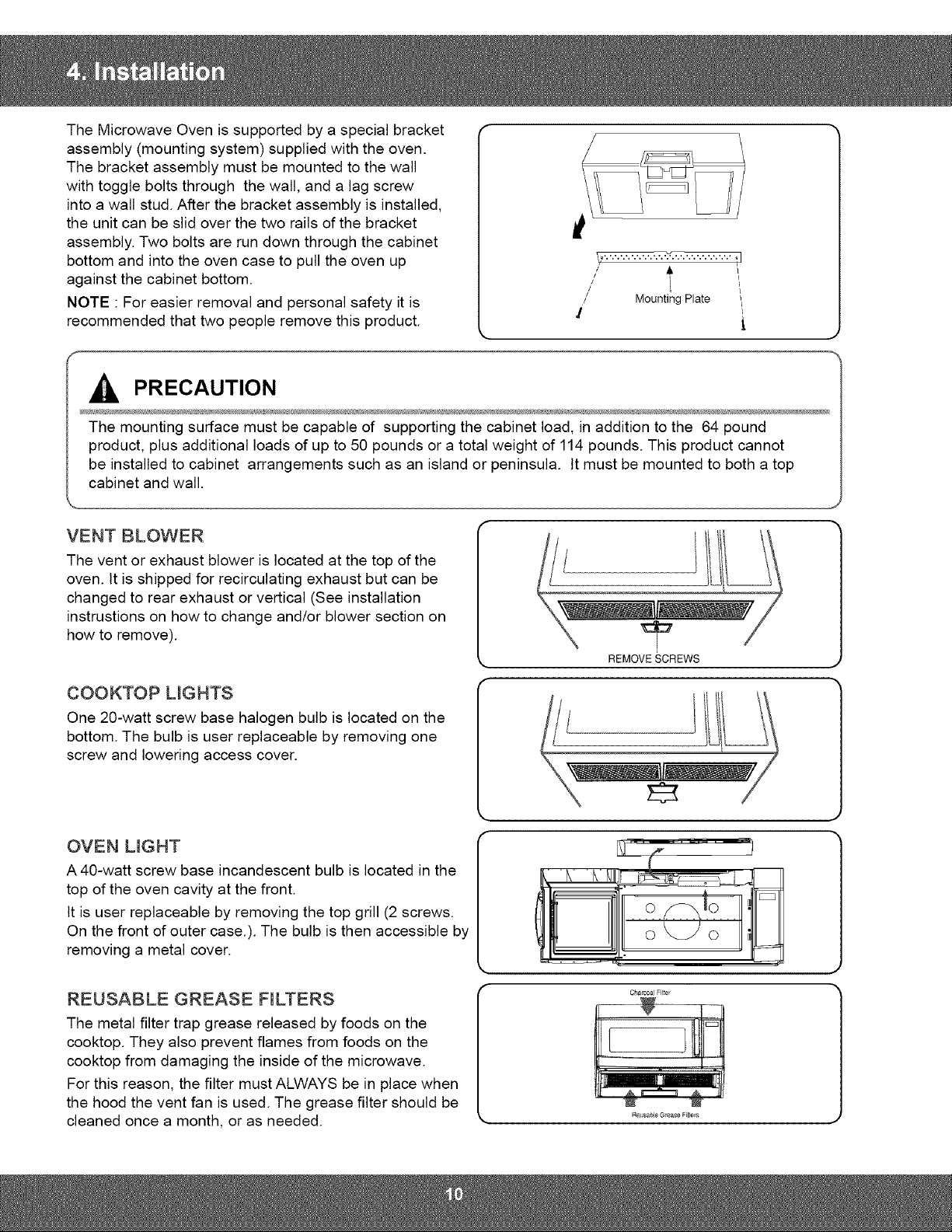
The Microwave Oven is supported by a special bracket
assembly (mounting system) supplied with the oven.
The bracket assembly must be mounted to the wall
with toggle bolts through the wall, and a lag screw
into a wall stud. After the bracket assembly is installed,
the unit can be slid over the two rails of the bracket
assembly. Two bolts are run down through the cabinet
bottom and into the oven case to pull the oven up
against the cabinet bottom.
NOTE : For easier removal and personal safety it is
recommended that two people remove this product.
II/ t
/
/ Mounting Plate
!
PRECAUTION
The mounting surface must be capable of supporting the cabinet load, in addition to the 64 pound
product, plus additional loads of up to 50 pounds or a total weight of 114 pounds. This product cannot
be installed to cabinet arrangements such as an island or peninsula. It must be mounted to both a top
cabinet and wall.
VENT BLOWER
The vent or exhaust blower is located at the top of the
oven. It is shipped for recirculating exhaust but can be
changed to rear exhaust or vertical (See installation
instrustions on how to change and/or blower section on
how to remove).
REMOVE SCREWS
COOKTOP LIGHTS
One 20-watt screw base halogen bulb is located on the
bottom. The bulb is user replaceable by removing one
screw and lowering access cover.
OVEN L_GHT
A 40-watt screw base incandescent bulb is located in the
top of the oven cavity at the front.
It is user replaceable by removing the top grill (2 screws.
On the front of outer case.). The bulb is then accessible by
removing a metal cover.
REUSABLE GREASE FILTERS
The metal filter trap grease released by foods on the
cooktop. They also prevent flames from foods on the
cooktop from damaging the inside of the microwave.
For this reason, the filter must ALWAYS be in place when
the hood the vent fan is used. The grease filter should be
cleaned once a month, or as needed.
Charcoal Flte
ReL;sable Grease F_lter s
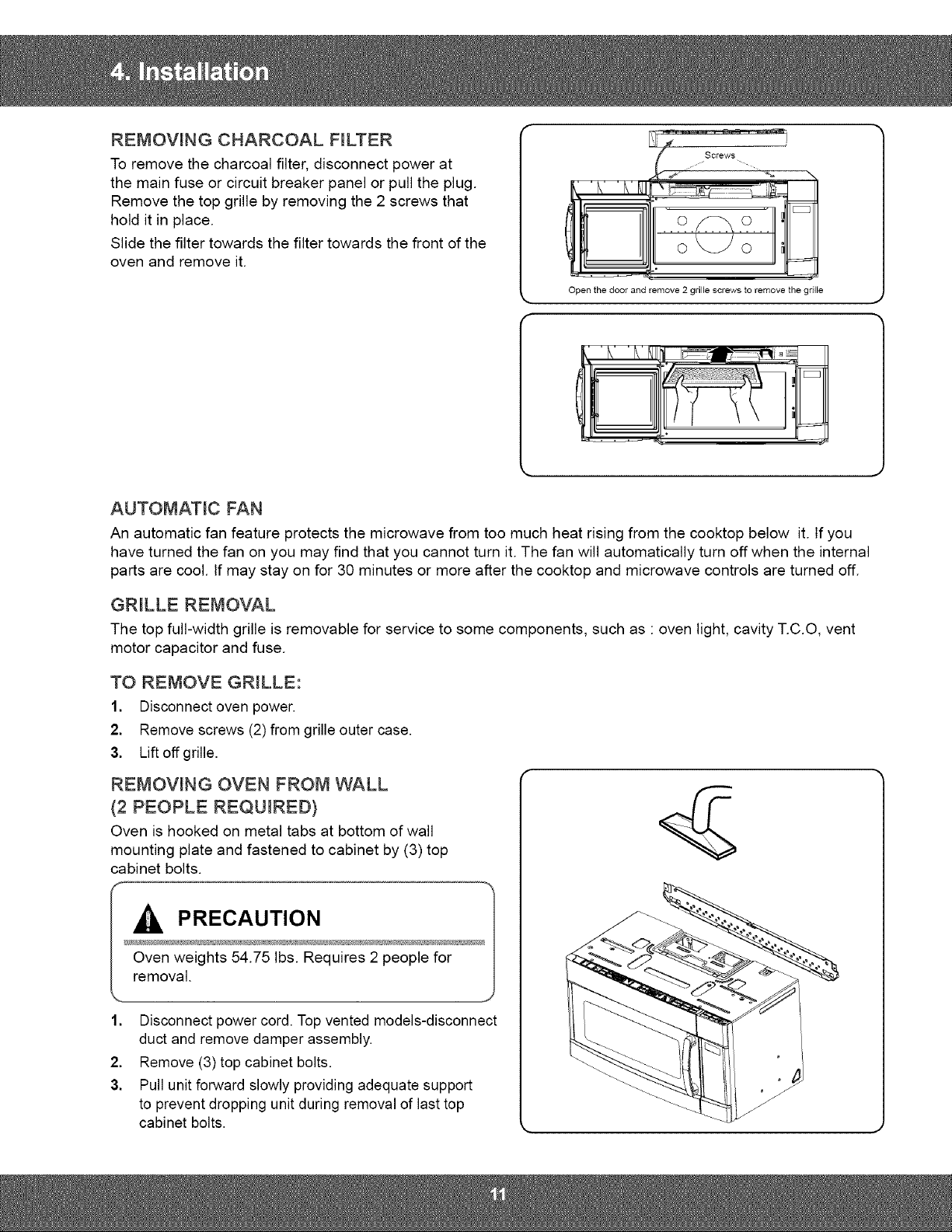
REMOVING CHARCOAL F_LTER
To remove the charcoal filter, disconnect power at
the main fuse or circuit breaker panel or pull the plug.
Remove the top grille by removing the 2 screws that
hold it in place.
Slide the filter towards the filter towards the front of the
oven and remove it.
Open the door and remove 2 grille screws to remove the gdlle
Screws
E_
AUTOMATIC FAN
An automatic fan feature protects the microwave from too much heat rising from the cooktop below it. If you
have turned the fan on you may find that you cannot turn it. The fan will automatically turn offwhen the internal
parts are cool. If may stay on for 30 minutes or more after the cooktop and microwave controls are turned off.
GRILLE REMOVAL
The top full-width grille is removable for service to some components, such as : oven light, cavity T.C.O, vent
motor capacitor and fuse.
TO REMOVE GRILLE:
1. Disconnect oven power.
2. Remove screws (2) from grille outer case.
3. Lift off grille.
REMOVING OVEN FROM WALL
(2 PEOPLE REQUIRED)
Oven is hooked on metal tabs at bottom of wall
mounting plate and fastened to cabinet by (3) top
cabinet bolts.
PRECAUTION
Oven weights 54.75 Ibs. Requires 2 people for
removal.
1. Disconnect power cord. Top vented models-disconnect
duct and remove damper assembly.
2. Remove (3) top cabinet bolts.
3. Pull unit forward slowly providing adequate support
to prevent dropping unit during removal of last top
cabinet bolts.

MAGNETRON, MOTOR ASSEMBLY, VENT BLOWER AND HIGH VOLTAGE TRANSFORMER
Oven must be removed from wall.
REMOVING OVEN FROM WALL (2 PEOPLE REQUIRED)
Oven is hooked on metal tabs at bottom of wall mounting plate and to cabinet by (3) top cabinet bolts.
,
Disconnect oven power.
2.
Gritte
Remove Grille.
1) Remove 2 screws
2) Slide the Grille to the left, then pull it
straght out.
Panet Outer
3. Remove Panel Outer.
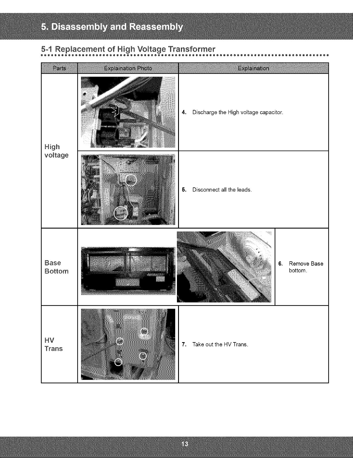
vottage
4. Discharge the High voltage capacitor.
S. Disconnect all the leads.
Base
HV
Trans
6. Remove Base
bottom.
7. Take out the HV Trans.

Remove the magnetron including the shield
case, permanent magnet, choke coils and
capacitors (all of which are contained in one
assembly).
1. Disconnect all lead wires from the
magnetron.
Magnetron
2. Remove nuts (4) securing the magnetron
to the wave guide.
3. Takeout the magnetron very carefully.
NOTE1: When removing the magnetron, make sure that itantenna does not hit any adjacentparts, or it may be
damaged.
NOTE2: When replacing the magnetron, be sure to remount the magnetron gasket in the correct position and make
sure the gasket is in good condition.
f
PRECAUTION
During replacement, be certain R.F. anode gasket is in place around anode stub.
PERFORM MICROWAVE LEAKAGE TEST

Removal of
Door Cap
Removat of
Door C
......
1. Insert flat screwdriver into the gap between Door
"A" and Door Cap to remove Door Cap
2,
Insert flat screwdriver into the gap between Door
"A" and Door "C" to remove Door "C".
• Be careful when handling Door "C" because it is
fragile.
Removal of
Key Door &
Spring
3, Detach the spring and key door from Door.

Removat of
Handte
4. Remove 2 screws, then handle is detached from
Door "A'.
Remove 2 screws then Following the procedure as
shown in the figure, insert and bend a thin metal
plate between Door "E" and Door "A" until you hear
the 'tick' sound.
• Insertion depth of the thin metal plate should be
0.5mm or less.

Fuse
Drive
The fuse is located on the noise filter.
1. Disconnect power and remove grille.
2. Replace the fuse.
3. When 20A fuse blows out by the operation
of interlock monitor switch failure, replace
the primary interlock switch, secondary
interlock switch, door sensing switch,
interlock monitor switch and power relay.
4. When the above four switches operate
properly, check if any other part such as the
control circuit board, blower motor or high
voltage transformer is defective.
1. Disconnect power and remove bottom plate
screws(5).
2. Remove bottom plate and disconnect the
turntable motor drive.
3. Remove turntable motor screws(I) and pull
the turntable motor out.
4. When replacing the drive motor, be sure to
remount it in the correct position with the
coupler.
S. Connect all the leads to the drive motor.
 Loading...