

Page 1

OWNERS MANUAL
EX500
500 WATT POWERED SUBWOOFER
SAMSON
®
Page 2
Safety Instructions
Important Safety Instructions
1. Please read all instructions before operating the unit.
2. Keep these instructions for future reference.
3. Please heed all safety warnings.
4. Follow manufacturers instructions.
5. Do not use this unit near water or moisture.
6. Clean only with a damp cloth.
7. Do not block any of the ventilation openings. Install in accordance with the manufacturers instructions.
8. Do not install near any heat sources such as radiators, heat registers, stoves, or other apparatus (including
amplifiers) that produce heat.
9. Do not defeat the safety purpose of the polarized or grounding-type plug. A polarized plug has two blades
with one wider than the other. A grounding type plug has two blades and a third grounding prong. The wide
blade or third prong is provided for your safety. When the provided plug does not fit your outlet, consult an
electrician for replacement of the obsolete outlet.
10. Protect the power cord from being walked on and pinched particularly at plugs, convenience receptacles and
at the point at which they exit from the unit.
11. Unplug this unit during lightning storms or when unused for long periods of time.
12. Refer all servicing to qualified personnel. Servicing is required when the unit has been damaged in any way,
such as power supply cord or plug damage, or if liquid has been spilled or objects have fallen into the unit,
the unit has been exposed to rain or moisture, does not operate normally, or has been dropped.
Caution: To reduce the hazard of electrical shock,
do not remove cover or back.
No user serviceable parts inside. Please refer all
servicing to qualified personnel.
WARNING: To reduce the risk of fire or electric shock, do not expose this unit to rain or moisture.
The lightning flash with an arrowhead symbol within an equilateral triangle, is intended to alert the user
to the presence of uninsulated "dangerous voltage" within the products enclosure that may be of sufficient magnitude to constitute a risk of electric shock to persons.
The exclamation point within an equilateral triangle is intended to alert the user to the presence of
important operating and maintenance (servicing) instructions in the literature accompanying the product.
FOR CONTINUED PROTECTION AGAINST RISK
OF FIRE, REPLACE ONLY WITH SAME TYPE FUSE
CAUTION
ATTENTION
UTILISER UN FUSIBLE DE
RECHANGE DE MÊME TYPE
WARNING
DO NOT EXPOSE THIS EQUIPMENT
TO RAIN OR MOISTURE
RISQUE DE CHOC ELECTRONIQUE
AVIS
NE PAS OUVRIR
RISK OF ELECTRIC SHOCK
DO NOT OPEN
Page 3

Table of Contents
Introduction 2
EX500 Features 3
Controls and Functions
Front Panel Layout 4
Rear Panel Layout 5
Configuring Your Speaker System 6
Operating the EX500
The EX500 Control Panel
EX500 Mono Sub with Powered Satellites 8
EX500 Stereo Sub with Powered Satellites 9
EX500 Mono Sub with Passive Satellites 10
EX500 Stereo Sub with Passive Satellites 11
EX500 Connections 12
Caster Installation 12
Specifications 13
Copyright 2001, Samson Technologies Corp.
Printed April, 2001
Samson Technologies Corp.
575 Underhill Blvd.
P.O. Box 9031
Syosset, NY 11791-9031
Phone: 1-800-3-SAMSON (1-800-372-6766)
Fax: 516-364-3888
www.samsontech.com
1
Page 4

Introduction
2
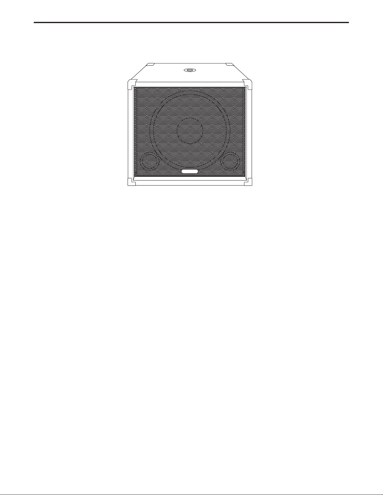
Thank you for purchasing the Expedition EX500 Subwoofer by Samson. The EX500 is a
self- powered, 500 Watt subwoofer featuring a 15” heavy duty driver, complemented by a
500 Watt, lightweight, Down Tracking Amplifier. The EX500 also offers an active stereo
crossover providing a high-passed output for running your satellite speakers. Solid 3/4 inch
plywood construction, steel corners, tough carpet covering and larger casters make the
EX500 a road warrior. In fixed installation systems, the EX500 provides super tight low frequency output in a relatively small, unobtrusive enclosure. The EX500 is a perfect add-on to
your Expedition system, or for any sound reinforcement system where extended low-end is
desired. While using your Expedition EX500, you’ll have great low-end anywhere.
In these pages, you’ll find a detailed description of the features of the EX500 Subwoofer, as
well as a guided tour through its front and rear panels, step-by-step instructions for its setup
and use, and full specifications. You’ll also find a warranty card enclosed—please don’t forget to fill it out and mail it in so that you can receive online technical support and so we can
send you updated information about these and other Samson products in the future.
With proper care and adequate air circulation, your EX500 will operate trouble free for many
years. We recommend you record your serial number in the space provided below for future
reference.
Serial number:
Date of purchase:
Should your unit ever require servicing, a Return Authorization number (RA) must be
obtained before shipping your unit to Samson. Without this number, the unit will not be
accepted. Please call Samson at 1-800-3SAMSON (1-800-372-6766) for a Return
Authorization number prior to shipping your unit. Please retain the original packing materials
and if possible, return the unit in the original carton and packing materials.
Page 5
EX500 Features
3
The Samson Expedition EX500 Powered Subwoofer utilizes the latest technology in loudspeaker and power
amplifier design. Here are some of its main features:
• Heavy-duty, 15 inch Low Frequency Transducer With Butyl Rubber Surround
• 500 Watt Down Tracking Power Amplifier
• Balanced High Pass Outputs for Satellite Speakers
• Variable Crossover 30 - 200 Hz
• Stereo / Mono Operation Switch
• Volume Control
• Heavy-Duty, Rear Mounted Casters
• Extra Large Grab Handles
• 35mm Pole Mount Receptacle
• 3/4” Plywood Construction, internally braced and covered in tough carpet.
• Three-year extended warranty
SAMSON
Page 6

4
Controls and Functions
1 GRILL SCREEN - Tough steel construction pro-
vides durable and stylish protection for speaker.
2 ENCLOSURE - Rigid 3/4” Plywood Construction.
3 POLE MOUNT - 1 3/8 inch (35mm) standard
speaker stand receptacle.
4 FINISH - Tough road-proof carpet.
5 TRANSDUCER - Heavy Duty 15” extended range
low frequency driver .
6 BUTYL RUBBER SURROUND - Assures maximum
excursion while maintaining tight bass response.
7 TUNED PORTS - Quiet port design offering
linear extended low frequency response.
8 CORNERS - Heavy Duty Steel corners
Front Panel Layout
1
2
3
SAMSON
4
5
7
86
Page 7

Controls and Functions
5
Rear Panel Layout
1 LEVEL - Controls the amount of output volume.
2 CROSSOVER FREQUENCY - Adjusts the low fre-
quency end range of the High-Pass outputs.
3 PEAK LED - Illuminates when the input signal is
overloading the power amplifier.
4 STEREO/MONO SWITCH - Selects stereo or
mono operation.
5 LEFT INPUT - Balanced XLR Input.
6 RIGHT INPUT - Balanced XLR Input.
.
7 LEFT OUTPUT - Balanced XLR Output.
8 RIGHT OUTPUT - Balanced XLR Output.
9 SERIAL NUMBER - Unit serial number is locat-
ed here.
10 VOLTAGE INDICATION - Designates AC input
voltage.
11 AC INLET - Accepts Standard Power Cord.
12 MAINS POWER SWITCH - Activates the EX500
power amplifier.
1
2
•
••
••
0510
LEVEL
3
Hz
105
••
•
30
200
SWEEP
5
4
BALANCED INPUTS BALANCED HIGH PASS OUTPUTS
••
STEREO
PEAK
MONO
•
LEFT
6
RIGHT
7
8
RIGHT
LEFT
POWERED SUBWOOFER 500 WATTS
60Hz
50Hz
EX500
A.C. MAINS
ON
OFF
12
POWER
SAMSON
ENGINEERED AND DESIGNED
IN THE UNITED STATES
BY SAMSON TECHNOLOGIES
AVIS;
POWER
RATING
RISQUE DE CHOC ELECTRIQUE
NE PAS OUVRIR
DO NOT EXPOSE THIS EQUIPMENT
TO RAIN OR MOISTURE.
MADE IN CHINA
9
115V/230V 50HZ/60Hz 500W
CAUTION
RISK OF ELECTRIC SHOCK
DO NOT OPEN
10
SERIAL
No.
115VAC
230VAC
11
Page 8

6
Configuring Your Speaker System
Before you start plugging in cables, you should take a minute to decide how you want to interface your new subwoofer. There are several ways you can interface the EX500, however most systems set-ups fall into two categories, Stereo or Mono (Common) sub operation.
Stereo Sub Operation
In larger rooms, as well as in theatres and
theme park installations (for low frequency
special audio effects), two EX500’s can be
used in stereo.
Common Sub Operation
In most cases a common sub, or mono
bass operation is desired. This is true for
several reasons, but mostly because low
frequencies produced by a subwoofer tend
to be non-directional. Since low frequency
waves take so much space to actually
develop, you can’t tell if the sub bass is
coming from the left or right side, unless of
course you’re in a very large room.
Because of this phenomena, just about all
sub bass material is mixed in mono.
SAMSON
SAMSON
SAMSON
Page 9

7
Operating the EX500
Level Control
The level control is used to adjust
the amount of volume from the
EX500 subwoofer. In addition, the
Level control will also control the
output volume of the high-passed
outputs. Therefore, if you are
using the EX500 without using the
high-passed outputs (for example,
when the EX500 is connected to
an external crossover) the Level
control adjusts the low frequency
output of the EX500. If you are
using the EX500’s internal electronic crossover to run satellite
speakers, then the Level control
will adjust the overall system volume.
Sweep
The Sweep control selects the upper range cutoff frequency of the EX500’s internal electronic crossover. The
EX500’s crossover provides a 12dB per octave Linkwisz- Riley filter curve. The Sweep limits the high frequency
that the EX500 will reproduce, and at the same time, the high-passed output tracks the selected crossover frequency as the lower limit frequency.
Stereo / Mono Switch
The Stereo/ Mono switch selects either stereo or mono bass operation. When set to MONO, the EX500 will combine, or sum, the left and right signals and send a mono signal to the amplifier of the EX500. In this mode, the
original stereo signal is passed through the left and right outputs only now the stereo signal is filtered at the frequency set by the sweep control. In Stereo mode, the low frequency signal is not summed, and you can choose
either the left or right input accordingly for each side of the system.
The In and The Outs
The EX500 feature electronically balanced inputs and outputs so that any possible HUM problems are greatly
reduced when interfacing to other equipment. XLR connectors with industry standard pin- outs are used for easy
interface from mixer and other professional audio gear. A detailed wiring diagram can be found in the section
EX500 Connections on page 12 of this manual.
The EX500’s control panel provides the connections and user interface to the EX500’s internal electronic
crossover and power amplifier section. The internal amplifier is a 500 Watt tracking amplifier capable of producing
incredible bass output while running super cool, and at the same time, weighing half as much as conventional
power amplifiers. EX500 employs an electronic crossover that adjusts the high frequency cutoff point for the subwoofer, and also, a high passed output for your satellite speakers. You will achieve a tremendous benefit in
sound quality by running your satellite speakers from the EX500’s High-Pass outputs. The reason for this is that
when your satellite speaker receives the filtered output from the EX500, it will no longer be looking at the frequencies below the crossover point. Let’s say your satellite speaker has a natural frequency roll-off at 70 Hz, and you
are sending full range signal (as low as 20Hz) to the satellite amplifier and speaker. Even though the speaker
can only reproduce 70Hz and up, the amplifier is still outputting 20-70Hz, which is wasted power and essentially
turns into heat. By using the EX500’s High-Pass output, the satellite amplifier and speaker never see the frequencies lower than what’s set by the Sweep frequency. This means you’ll have more power dedicated to the
frequencies you want the satellites to deliver, resulting in a much cleaner sound with more headroom.
EX500 CONTROL PANEL
Hz
105
••
••
••
0510
LEVEL
••
•
30
SWEEP
•
200
PEAK
••
STEREO
MONO
POWERED SUBWOOFER 500 WATTS
BALANCED INPUTS BALANCED HIGH PASS OUTPUTS
LEFT
RIGHT
LEFT
RIGHT
Page 10

8
Operating the EX500
The EX500 is a perfect addition to any pair of powered full range enclosures like the Samson EX20 and EX30.
Below is a typical system set-up using the EX500 with a mixer and a pair of powered satellite loudspeakers. The
EX500’s input and outputs utilize industry standard XLR connectors. For a detailed wiring diagram, see the section EX500 Connections on page 12. Follow the steps below the diagram to set up your system.
EX500 MONO SUB WITH POWERED SATELLITES
• Connect the mixer’s left output to the EX500’s left
input and the mixer’s right output to the EX500’s right
input. Now connect the EX500’s left output to the
input of the left side powered satellite, and the
EX500’s right output to the input of the right side
satellite. Switch the Stereo/Mono selector switch to
the MONO position.
• Now adjust the crossover SWEEP to the desired fre-
quency. For the Expedition EX20 & EX30 select 80100Hz. If you are using another brand of powered
speaker as satellites with the EX500, consult their
respective owners manuals for the recommended
crossover point.
• Lower your mixer’s master outputs to all the way off.
Now set the level of your powered satellites up to the
normal operating level. Run an audio signal (like
some music from a CD) through your mixer and raise
the level to a comfortable listening volume. Now
slowly raise the EX500 Level control and listen to the
low frequency output. Adjust the EX500 to the level
of low frequency output that you like. Now, when
you raise and lower your mixer’s output, the EX500
and satellites will track at the same relative volume.
O
T
EX20 EX20
5
0
10
PL1602 Mixer
PL 1602
16 CHANNEL LINE MIXER
110
DO NOT EXPOSE THIS EQUIPMENT
POWER
RATING
~115V(0.3A)
230V(0.15A)
50/60Hz 30W
EX500
POWER
AVIS:
RISQUE DE CHOC ELECTRIQUE
NE PAS OUVRIR
TO RAIN OR MOISTURE
120V - 60 Hz 35W
CAUTION
RISK OF ELECTRIC SHOCK
DO NOT OPEN
ON
OFF
S / N
BALANCED 600 +4db
!
TIP + RING - SLEEVE GND
MIXER LINKING
BUS
INSERTS
INPUTS BALANCED 10K‰ -30 to +4db TIP + RING - SLEEVE GND.
2R
1L2R3L4RLRLR
AUX SEND
AUX
RETURNS
UNBALANCED
2K‰ +4db
UNBALANCED 10K‰
STEREO
!
MONO
BALANCED INPUTS BALANCED HIGH PASS OUTPUTS
105
••
••
PEAK
STEREO
••
••
MONO
•
••
•
30
200Hz0510
LEVEL
SWEEP
RIGHT
LEFT
POWERED SUBWOOFER 500 WATTS
SAMSON
ENGINEERED AND DESIGNED
SERIAL
IN THE UNITED STATES
No.
BY SAMSON TECHNOLOGIES
AVIS;
POWER
115V/230V 50HZ/60Hz 500W
RATING
RISQUE DE CHOC ELECTRIQUE
NE PAS OUVRIR
60Hz
115VAC
DO NOT EXPOSE THIS EQUIPMENT
CAUTION
TO RAIN OR MOISTURE.
50Hz
230VAC
RISK OF ELECTRIC SHOCK
DO NOT OPEN
MADE IN CHINA
LEFT
A.C. MAINS
SAMSON TECHNOLOGIES CORP., NEW YORK, U.S.A.
6R 5L 4R 3L 2R 1L
1L
INSERTS TIP RETURN RING SEND
RIGHT
EX500
POWER
ON
OFF
MIC 1
-10
2
3
0
1
-40+4
TRIM
1L2R3L4R5L6R7L8R9L10R11L12R13L14R15L16R
-10
2
3
0
1
-40+4
TRIM
MIC 3MAIN OUT
5
0
10
!
BALA
Hz
105
••
••
••
0510
LEVEL
••
PEAK
••
•
•
30
200
SWEEP
STEREO
MONO
LEF
POWERED SUBW
Page 11

9
EX500 STEREO SUB WITH POWERED SATELLITES
Operating the EX500
Two EX500’s can be used with any pair of powered full range enclosures like the Samson EX20 and EX30.
Below is a typical system set-up using two EX500’s with a mixer and a pair of powered satellite loudspeakers.
The EX500’s inputs and outputs utilize industry standard XLR connectors. For a detailed wiring diagram, see the
section EX500 Connections on page 12. Follow the steps below the diagram to set up your system.
• Connect the mixer’s left output to the left-side
EX500’s left input and the mixer’s right output to the
right-side EX500’s right input. Now connect the leftside EX500’s left output to the input of the left powered satellite, and right-side EX500’s right output to
the input of the right satellite. Switch both the
Stereo/Mono selector switches to the Stereo position.
• Now adjust the crossover SWEEP to the desired frequency. For the Expedition EX20 & EX30 select 80100Hz. If you are using another brand of powered
speaker as satellites with the EX500, consult their
respective owners manuals for the recommended
crossover point.
• Lower your mixer’s master outputs to all the way off.
Now set the level of your powered satellites up to the
normal operating level. Run an audio signal (like
some music from a CD) through your mixer and raise
the level to a comfortable listening volume. Now
slowly raise the EX500 Level control and listen to the
low frequency output. Adjust the EX500 to the level
to low frequency output that you like. Now when you
raise and lower your mixer’s output, the EX500 and
satellites will track at the same relative volume.
O
T
EX20 EX20
5
0
10
PL1602 Mixer
PL 1602
16 CHANNEL LINE MIXER
S / N
POWER
110
ON
OFF
AVIS:
RISQUE DE CHOC ELECTRIQUE
NE PAS OUVRIR
DO NOT EXPOSE THIS EQUIPMENT
TO RAIN OR MOISTURE
POWER
120V - 60 Hz 35W
RATING
BUS
!
CAUTION
INSERTS
BALANCED 600 +4db
RISK OF ELECTRIC SHOCK
~115V(0.3A)
!
MIXER LINKING
TIP + RING - SLEEVE GND
DO NOT OPEN
230V(0.15A)
50/60Hz 30W
INPUTS BALANCED 10K‰ -30 to +4db TIP + RING - SLEEVE GND.
2R
1L2R3L4RLRLR
AUX
AUX SEND
RETURNS
UNBALANCED
UNBALANCED 10K‰
2K‰ +4db
SAMSON TECHNOLOGIES CORP., NEW YORK, U.S.A.
6R 5L 4R 3L 2R 1L
1L
EX500 EX500
STEREO
BALANCED INPUTS BALANCED HIGH PASS OUTPUTS
105
••
••
PEAK
STEREO
••
MONO
••
MONO
•
••
•
30
200Hz0510
LEVEL
SWEEP
RIGHT
LEFT
POWERED SUBWOOFER 500 WATTS
SAMSON
ENGINEERED AND DESIGNED
SERIAL
IN THE UNITED STATES
No.
BY SAMSON TECHNOLOGIES
AVIS;
POWER
115V/230V 50HZ/60Hz 500W
RATING
RISQUE DE CHOC ELECTRIQUE
NE PAS OUVRIR
60Hz
115VAC
DO NOT EXPOSE THIS EQUIPMENT
CAUTION
TO RAIN OR MOISTURE.
50Hz
230VAC
RISK OF ELECTRIC SHOCK
DO NOT OPEN
MADE IN CHINA
RIGHT
LEFT
EX500
POWER
A.C. MAINS
ON
OFF
INSERTS TIP RETURN RING SEND
-10
0
-40+4
TRIM
1L2R3L4R5L6R7L8R9L10R11L12R13L14R15L16R
-10
0
-40+4
TRIM
STEREO
MONO
5
0
10
MIC 1
2
3
1
2
3
1
MIC 3MAIN OUT
BALANCED INPUTS BALANCED HIGH PASS OUTPUTS
105
••
••
PEAK
STEREO
••
••
MONO
•
••
•
30
200Hz0510
LEVEL
SWEEP
LEFT
RIGHT
LEFT
POWERED SUBWOOFER 500 WATTS
EX500
SAMSON
A.C. MAINS
ENGINEERED AND DESIGNED
SERIAL
IN THE UNITED STATES
No.
BY SAMSON TECHNOLOGIES
AVIS;
POWER
115V/230V 50HZ/60Hz 500W
RATING
RISQUE DE CHOC ELECTRIQUE
NE PAS OUVRIR
60Hz
115VAC
DO NOT EXPOSE THIS EQUIPMENT
CAUTION
TO RAIN OR MOISTURE.
50Hz
230VAC
RISK OF ELECTRIC SHOCK
DO NOT OPEN
MADE IN CHINA
!
RIGHT
POWER
ON
OFF
BALA
Hz
105
••
••
••
0510
LEVEL
••
PEAK
••
•
•
30
200
SWEEP
STEREO
MONO
LEF
POWERED SUBW
Page 12

10
Operating the EX500
EX500 MONO SUB WITH PASSIVE SATELLITES
If your system uses a standard stereo power amp and passive full range enclosures, like the Samson EX10, the
EX500 is easily interfaced for extended bass. Below is a typical system set-up using the EX500 with a mixer,
stereo power amp and a pair of passive satellite loudspeakers.The EX500’s inputs and outputs utilize industry
standard XLR connectors. For a detailed wiring diagram, see the section EX500 Connections on page 1. Follow
the steps below the diagram to set up your system.
• Lower your mixer’s master outputs to all the way off.
• Connect the mixer’s left output to the EX500’s left input and the mixer’s right output to the EX500’s right
input. Now connect the EX500’s left outputs to the left side input of your power amp, and EX500’s right
output to the right side input of your power amp. Run your speaker cables from the power amp’s outputs
to the left and right satellite speakers. Switch the Stereo/Mono
selector switch to the MONO position.
• Now adjust the crossover SWEEP to the desired frequency.
For the Expedition EX20 & EX30 select 80-100Hz. If you are
using another brand of powered speaker as satellites with the
EX500, consult their respective owners manuals for the recommended crossover point.
• Set the level of your power amplifiers to the normal operating
level. Run an audio signal (like some music from a CD) through
your mixer and raise the level to a comfortable listening volume.
Now, slowly raise the EX500 Level control and listen to the low
frequency output. Adjust the EX500 to the level of low frequency output that you like. Now when you raise and lower your
mixer’s output, the EX500 and satellites will track at the same
relative volume.
F
L
EX10 EX10
PL1602 Mixer
PL 1602
16 CHANNEL LINE MIXER
POWER
110
ON
OFF
AVIS:
RISQUE DE CHOC ELECTRIQUE
NE PAS OUVRIR
DO NOT EXPOSE THIS EQUIPMENT
TO RAIN OR MOISTURE
POWER
120V - 60 Hz 35W
RATING
CAUTION
RISK OF ELECTRIC SHOCK
~115V(0.3A)
!
TIP + RING - SLEEVE GND
DO NOT OPEN
230V(0.15A)
50/60Hz 30W
S / N
BALANCED 600 +4db
MIXER LINKING
BUS
INSERTS
INPUTS BALANCED 10K‰ -30 to +4db TIP + RING - SLEEVE GND.
1L2R3L4RLRLR
AUX
RETURNS
UNBALANCED 10K‰
EX500
STEREO
BALANCED INPUTS BALANCED HIGH PASS OUTPUTS
105
••
••
PEAK
STEREO
••
510W (115V)900W (230V)
••
MONO
•
•
••
30
200Hz0510
LEVEL
SWEEP
RIGHT
LEFT
POWERED SUBWOOFER 500 WATTS
SAMSON
ENGINEERED AND DESIGNED
SERIAL
IN THE UNITED STATES
No.
BY SAMSON TECHNOLOGIES
AVIS;
POWER
115V/230V 50HZ/60Hz 500W
RATING
RISQUE DE CHOC ELECTRIQUE
NE PAS OUVRIR
60Hz
115VAC
DO NOT EXPOSE THIS EQUIPMENT
CAUTION
TO RAIN OR MOISTURE.
50Hz
230VAC
RISK OF ELECTRIC SHOCK
DO NOT OPEN
MADE IN CHINA
SERVO 550 STUDIO AMPLIFIER
!
GROUND
LEFT+
~AC INPUT
115V/230W, 50/60HZ
MONO
Servo 550
CAUTION
RISK OF ELECTRIC SHOCK
DO NOT OPEN
F
E
U
S
SERIAL
FUSE
NUMBER
FUSE RATING
12A/250V (115V)
6A/250V (230V)
USE CLASS 2 WIRING MAXIMUM LOAD IMPEDANCE 4Ω
CAUTION
HEATSINK MAY BE
HOT! DO NOT BLOCK
AIRFLOW OR OVERHEATING MAY OCCUR
TO PREVENT SHOCK DO
+RIGHT
NOT OPEN. NO USER
SERVICABLE PARTS
INSIDE. REFER SERVICING
OUTPUT 250W/4Ω
TO QUALIFIED SERVICE
PERSONNEL. TO PREVENT
FIRE OR SHOCK HAZARD
RIGHT
LEFT
SAMSON TECHNOLOGIES CORP., NEW YORK, U.S.A.
2R
6R 5L 4R 3L 2R 1L
1L
AUX SEND
INSERTS TIP RETURN RING SEND
UNBALANCED
2K‰ +4db
RIGHT
LEFT
EX500
POWER
A.C. MAINS
ON
OFF
SAMSON TECHNOLOGIES CORP., HICKSVILLE, NEW YORK
MIC 1
-10
2
3
0
1
-40+4
TRIM
1L2R3L4R5L6R7L8R9L10R11L12R13L14R15L16R
-10
2
3
0
1
-40+4
TRIM
MIC 3MAIN OUT
BRIDGED
MONO STEREO
LEFT
RIGHT
INPUTS
(BALANCED
10KΩ/0dBm0)
TIP RING SLEEVE
TIP +
RING -
SLEEVE GND
••
••
0510
LEVEL
Hz
105
••
••
••
•
•
30
200
SWEEP
PEAK
STEREO
MONO
BA
LE
Page 13

EX500 STEREO SUB WITH PASSIVE SATELLITES
11
Operating the EX500
If your system uses a standard stereo power amp and passive full range enclosures, like the Samson EX10, the
EX500 is easily interfaced for extended bass. Below is a typical system set-up using the EX500 with a mixer,
stereo power amp and a pair of passive satellite loudspeakers.The EX500’s inputs and outputs utilize industry
standard XLR connectors. For a detailed wiring diagram, see the section EX500 Connections on page 12.
Follow the steps below the diagram to set up your system.
• Lower your mixer’s master outputs to all the way off.
• Connect the mixer’s left output to the left-side EX500’s left input and the mixer’s right out-
put to the right-side EX500’s right input. Now connect the left-side EX500’s left output to
the left input of the power amplifier and the EX500’s right output to the the power amp’s
right input. Run your speaker cables from the power amp’s outputs to the left and right satellite speakers. Switch both the
Stereo/Mono selector switches to the Stereo position.
• Now adjust the crossover SWEEP to the desired frequency.
For the Expedition EX10 select 80-100Hz. If you are using
another brand of speakers as satellites with the EX500, consult
their respective owners manuals for the recommended
crossover point.
• Set the level of your power amplifiers to the normal operating
level. Run an audio signal (like some music from a CD)
through your mixer and raise the level to a comfortable listening
level. Now slowly raise the EX500 Level control and listen to
the low frequency output. Adjust the EX500 to the level of low
frequency output that you like. Now when you raise and lower
your mixer’s output, the EX500 and satellites will track at the
same relative volume.
O
E
EX10 EX10
Servo 550
F
E
U
S
SERIAL
FUSE
NUMBER
FUSE RATING
12A/250V (115V)
6A/250V (230V)
USE CLASS 2 WIRING MAXIMUM LOAD IMPEDANCE 4Ω
CAUTION
HEATSINK MAY BE
HOT! DO NOT BLOCK
AIRFLOW OR OVER-
HEATING MAY OCCUR
TO PREVENT SHOCK DO
NOT OPEN. NO USER
SERVICABLE PARTS
INSIDE. REFER SERVICING
TO QUALIFIED SERVICE
PERSONNEL. TO PREVENT
RIGHT
LEFT
SERVO 550 STUDIO AMPLIFIER
CAUTION
RISK OF ELECTRIC SHOCK
!
DO NOT OPEN
GROUND
+RIGHT
LEFT+
OUTPUT 250W/4Ω
~AC INPUT
115V/230W, 50/60HZ
510W (115V)900W (230V)
SAMSON TECHNOLOGIES CORP., HICKSVILLE, NEW YORK
BRIDGED
MONO STEREO
LEFT
RIGHT
INPUTS
(BALANCED
10KΩ/0dBm0)
TIP RING SLEEVE
TIP +
RING SLEEVE GND
EX500 EX500
STEREO
MONO
BALANCED INPUTS BALANCED HIGH PASS OUTPUTS
105
••
••
STEREO
PEAK
••
••
MONO
•
••
•
30
200Hz0510
LEVEL
SWEEP
RIGHT
LEFT
POWERED SUBWOOFER 500 WATTS
SAMSON
ENGINEERED AND DESIGNED
SERIAL
IN THE UNITED STATES
No.
BY SAMSON TECHNOLOGIES
AVIS;
POWER
115V/230V 50HZ/60Hz 500W
RATING
RISQUE DE CHOC ELECTRIQUE
NE PAS OUVRIR
60Hz
115VAC
DO NOT EXPOSE THIS EQUIPMENT
CAUTION
TO RAIN OR MOISTURE.
50Hz
230VAC
RISK OF ELECTRIC SHOCK
DO NOT OPEN
MADE IN CHINA
RIGHT
LEFT
EX500
POWER
A.C. MAINS
ON
OFF
PL1602 Mixer
PL 1602
16 CHANNEL LINE MIXER
S / N
POWER
110
ON
OFF
AVIS:
RISQUE DE CHOC ELECTRIQUE
NE PAS OUVRIR
DO NOT EXPOSE THIS EQUIPMENT
TO RAIN OR MOISTURE
POWER
120V - 60 Hz 35W
RATING
CAUTION
RISK OF ELECTRIC SHOCK
~115V(0.3A)
!
DO NOT OPEN
TIP + RING - SLEEVE GND
230V(0.15A)
50/60Hz 30W
BALANCED 600 +4db
MIXER LINKING
INSERTS
BUS
INPUTS BALANCED 10K‰ -30 to +4db TIP + RING - SLEEVE GND.
2R
1L2R3L4RLRLR
AUX
AUX SEND
UNBALANCED
RETURNS
UNBALANCED 10K‰
2K‰ +4db
1L
SAMSON TECHNOLOGIES CORP., NEW YORK, U.S.A.
1L2R3L4R5L6R7L8R9L10R11L12R13L14R15L16R
6R 5L 4R 3L 2R 1L
INSERTS TIP RETURN RING SEND
STEREO
MONO
MIC 1
-10
2
3
0
1
-40+4
TRIM
-10
2
3
0
1
-40+4
TRIM
MIC 3MAIN OUT
BALANCED INPUTS BALANCED HIGH PASS OUTPUTS
105
••
••
STEREO
PEAK
••
••
MONO
•
••
•
30
200Hz0510
LEVEL
SWEEP
RIGHT
LEFT
POWERED SUBWOOFER 500 WATTS
SAMSON
ENGINEERED AND DESIGNED
SERIAL
IN THE UNITED STATES
No.
BY SAMSON TECHNOLOGIES
AVIS;
POWER
115V/230V 50HZ/60Hz 500W
RATING
RISQUE DE CHOC ELECTRIQUE
NE PAS OUVRIR
60Hz
115VAC
DO NOT EXPOSE THIS EQUIPMENT
CAUTION
TO RAIN OR MOISTURE.
50Hz
230VAC
RISK OF ELECTRIC SHOCK
DO NOT OPEN
MADE IN CHINA
RIGHT
LEFT
EX500
POWER
A.C. MAINS
ON
OFF
Hz
105
••
••
••
0510
••
LEVEL
•
30
SWEEP
••
•
200
PEAK
STER
MON
Page 14

12
Connections
XLR Balanced Wiring Guide
The EX500’s input and outputs utilize industry standard XLR connectors. Below is a detailed wiring diagram for
the EX500 XLR connectors.
EX500 XLR WIRING DIAGRAM
CASTER INSTALLATION
• Locate the four casters in the EX500
shipping carton.
• Now locate the four caster receptacles which you’ll find in the four corners on the back of the unit.
• Insert the caster into the receptacle
until you feel the caster snap into
place.
• Turn the EX500 on its back for easy
transport.
Hot
Cold
Hot (2)
Common (1) Common
2
12
3
End View Solder Points
1
3
Cold (3)
Female XLR
Male XLR
Common (1)Common
Hot (2)
1
Solder Points End View
Cold (3)
2
3
Hot
Cold
21
3
Page 15

13
Specifications
Specifications
Transducer: 15", Heavy Duty Driver, 3 inch voice coil, aluminum former
Amplifier: High-efficiency tracking converter
Power Rating: 500 Watts RMS
Frequency response 30Hz- 300Hz+/-3 dB
Sensitivity: 94dB SPL @ 1 W/1m
Input Balanced
Connector: XLR - FEMALE
Output Balanced, high-passed tracking low frequency crossover point
Connector: XLR - MALE
Crossover Frequency: Variable 30Hz – 200Hz
Switch Functions
Stereo /Mono: Selects stereo or mono low frequency operation
Enclosure
Construction: 3/4" plywood, carpet covered
Finish: Black carpet
Corners: Steel
Casters: Three Inch Heavy Duty
Mounting: Integral 1 3/8" (35mm) Pole Mount Receptacle,
Dimensions: 20” (508mm) H x 24” (610 mm) W x 22.75” (578mm) D
Weight: 71 lbs. (32.25K)
Page 16

Samson Technologies Corp.
575 Underhill Blvd.
P.O. Box 9031
Syosset, NY 11791-9031
Phone: 1-800-3-SAMSON (1-800-372-6766)
Fax: 516-364-3888
www.samsontech.com
 Loading...