

Page 1
EB 8048-2/-3 EN
Translation of original instructions
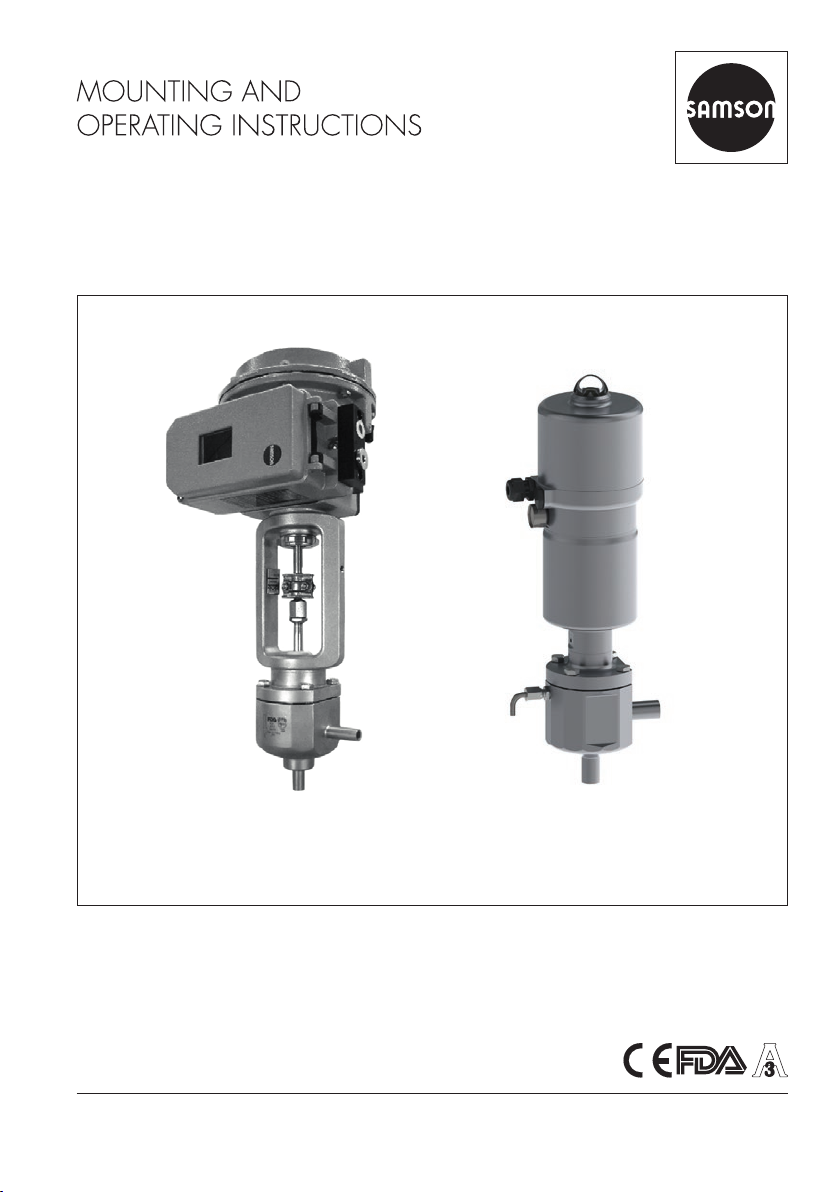
Type3349-7 Control Valve with
Type3730 Electropneumatic Positioner
Type3349/3379 Control Valve with
Type3724 Positioner
Type3349 Aseptic Angle Valve with USP-VI diaphragm
In combination with an actuator,
e.g. a SAMSON Type3271 or Type3277 Pneumatic Actuator or
Type3379 Pneumatic Actuator
Edition March 2017
Page 2
Note on these mounting and operating instructions
These mounting and operating instructions assist you in mounting and operating the device
safely. The instructions are binding for handling SAMSON devices.
Î For the safe and proper use of these instructions, read them carefully and keep them for
later reference.
Î If you have any questions about these instructions, contact SAMSON‘s After-sales Service
Department (aftersalesservice@samson.de).
The mounting and operating instructions for the devices are included in
the scope of delivery. The latest documentation is available on our website
at www.samson.de > Service & Support > Downloads > Documentation.
Denition of signal words
!
DANGER
Hazardous situations which, if not avoided,
will result in death or serious injury
!
WARNING
Hazardous situations which, if not avoided,
could result in death or serious injury
2 EB 8048-2/-3 EN
!
NOTICE
Property damage message or malfunction
Note
Additional information
Tip
Recommended action
Page 3

Contents
1 Safety instructions and measures ...................................................................5
1.1 Notes on possible severe personal injury .........................................................7
1.2 Notes on possible personal injury ...................................................................8
1.3 Notes on possible property damage ................................................................9
2 Markings on the control valve ......................................................................10
2.1 Body inscription ...........................................................................................10
2.2 Actuator nameplate ......................................................................................10
2.3 Material number ..........................................................................................10
3 Design and principle of operation ................................................................12
3.1 Fail-safe positions ........................................................................................12
3.2 Versions ......................................................................................................15
4 Measures for preparation ............................................................................20
4.1 Unpacking ..................................................................................................20
4.2 Transporting and lifting ................................................................................20
4.2.1 Transporting ................................................................................................21
4.2.2 Lifting ..........................................................................................................21
4.3 Storage .......................................................................................................23
4.4 Preparation for installation ............................................................................24
5 Mounting and start-up .................................................................................26
5.1 Mounting the actuator onto the valve .............................................................26
5.1.1 Version with Type3271 or Type3277 Actuator ..............................................26
5.1.2 Version with Type3379 Actuator ..................................................................27
5.2 Installing the valve into the pipeline ...............................................................28
5.2.1 Checking the installation conditions ...............................................................28
5.2.2 Installing the control valve .............................................................................30
5.3 Preparing for operation ................................................................................30
5.4 Quick check ................................................................................................31
6 Operation ...................................................................................................32
6.1 CIP (cleaning-in-place) .................................................................................33
6.2 SIP (sterilization-in-place) .............................................................................33
EB 8048-2/-3 EN 3
Page 4

Contents
7 Servicing.....................................................................................................34
7.1 Version with Type3271 or Type3277 Actuator ..............................................35
7.1.1 Replacing the packing ..................................................................................35
7.1.2 Replacing the diaphragm and plug ...............................................................37
7.2 Version with Type3379 Actuator ..................................................................39
7.2.1 Replacing the packing ..................................................................................39
7.2.2 Replacing the diaphragm and plug ...............................................................40
7.3 Checking the concentricity of the plug to the plug stem ....................................42
7.4 Preparation for return shipment .....................................................................42
7.5 Ordering spare parts and operating supplies .................................................43
8 Malfunctions ...............................................................................................44
8.1 Troubleshooting ...........................................................................................44
8.2 Emergency action ........................................................................................45
9 Decommissioning and disassembly ..............................................................46
9.1 Decommissioning .........................................................................................46
9.2 Removing the valve from the pipeline .............................................................46
9.3 Removing the actuator from the valve ............................................................47
9.4 Disposal ......................................................................................................47
10 Annex.........................................................................................................48
10.1 After-sales service ........................................................................................48
10.2 Certicates ..................................................................................................49
10.3 Spare parts .................................................................................................50
4 EB 8048-2/-3 EN
Page 5

Safety instructions and measures
1 Safety instructions and measures
Intended use
The SAMSON Type3349 Angle Valve in combination with an actuator (e.g. Type3271,
Type3277 or Type3379 Pneumatic Actuator) is designed to regulate the ow rate, pressure
or temperature of liquids, gases or vapors. The angle valve is suitable for use in aseptic applications (e.g. in the pharmaceutical and food industries).
The valve with its actuator is designed to operate under exactly dened conditions (e.g.
operating pressure, process medium, temperature). Therefore, operators must ensure that the
control valve is only used in applications that meet the specications used for sizing the valve
at the ordering stage. In case operators intend to use the control valve in other applications
or conditions than specied, contact SAMSON.
SAMSON does not assume any liability for damage resulting from the failure to use the
valve for its intended purpose or for damage caused by external forces or any other external
factors.
Î Refer to the technical data and nameplate for limits and elds of application as well as
possible uses.
Reasonably foreseeable misuse
The control valve is not suitable for the following applications:
− Use outside the limits dened during sizing and in the technical data
− Use outside the limits dened by the valve accessories mounted on the control valve
Furthermore, the following activities do not comply with the intended use:
− Use of non-original spare parts
− Performing service and repair work not described in these instructions
Qualications of operating personnel
The control valve must be mounted, started up, serviced, and repaired by fully trained and
qualied personnel only; the accepted industry codes and practices are to be observed.
According to these mounting and operating instructions, trained personnel refers to
individuals who are able to judge the work they are assigned to and recognize possible
hazards due to their specialized training, their knowledge and experience as well as their
knowledge of the applicable standards.
EB 8048-2/-3 EN 5
Page 6

Safety instructions and measures
Personal protective equipment
We recommend wearing the following protective equipment depending on the process medium:
− Protective clothing, gloves, and eyewear in applications with hot, cold, and/or corrosive
media
− Wear hearing protection when working near the valve.
Î Check with the plant operator for details on further protective equipment.
Revisions and other modications
Revisions, conversions or other modications to the product are not authorized by SAMSON.
They are performed at the user's own risk and may lead to safety hazards, for example. Furthermore, the product may no longer meet the requirements for its intended use.
Safety features
Upon supply air or control signal failure, the valve moves to its fail-safe position (see section3.1). The fail-safe action of the actuator is the same as its direction of action and is specied on the nameplate of SAMSON actuators (see actuator documentation).
Warning against residual hazards
To avoid personal injury or property damage, plant operators and operating personnel must
prevent hazards that could be caused in the control valve by the process medium, the operating pressure, the signal pressure or by moving parts by taking appropriate precautions. They
must observe all hazard statements, warning and caution notes in these mounting and operating instructions, especially for installation, start-up, and service work.
Responsibilities of the operator
The operator is responsible for proper operation and compliance with the safety regulations.
Operators are obliged to provide these mounting and operating instructions as well as the
referenced documents to the operating personnel and to instruct them in proper operation.
Furthermore, the operator must ensure that operating personnel or third persons are not
exposed to any danger.
Responsibilities of operating personnel
Operating personnel must read and understand these mounting and operating instructions as
well as the referenced documents and observe the hazard statements, warning and caution
notes specied in them. Furthermore, the operating personnel must be familiar with the applicable health, safety and accident prevention regulations and comply with them.
6 EB 8048-2/-3 EN
Page 7

Safety instructions and measures
Referenced standards and regulations
The control valves meet the requirements in the Regulation (EC) No.1935/2004 for materials and articles intended to come into contact with food
The control valves comply with the requirements of the European Pressure Equipment
Directive 2014/68/EU. This declaration of conformity is included in the Appendix of these
instructions (see section10.2).
According to the ignition risk assessment performed in accordance with EN13463-1:2009,
section 5.2, the non-electrical control valves do not have their own potential ignition source
even in the rare incident of an operating fault. As a result, they do not fall within the scope of
Directive 2014/34/EU.
Î For connection to the equipotential bonding system, observe the requirements specied in
section 6.4 of EN60079-14 (VDE0165 Part 1).
Referenced documentation
The following documents apply in addition to these mounting and operating instructions:
− Mounting and operating instructions for mounted actuator, e.g. uEB8310-X for
Type3271 and Type3277 Actuators or uEB8315 for Type3379 Actuator
− Mounting and operating instructions for mounted valve accessories (positioner, solenoid
valve etc.) e.g. uEB8395 for Type3724 Positioner
− uAB0100 for tools, tightening torques, and lubricant
1.1 Notes on possible severe personal injury
!
DANGER
Risk of bursting in pressure equipment.
Control valves and pipelines are pressure equipment. Improper opening can lead to
valve components bursting.
Î Before starting any work on the control valve, depressurize all plant sections
concerned as well as the valve.
Î Drain the process medium from all the plant sections concerned as well as the
valve.
Î Wear personal protective equipment.
EB 8048-2/-3 EN 7
Page 8

Safety instructions and measures
1.2 Notes on possible personal injury
!
WARNING
Crush hazard arising from moving parts.
The Type3349-1 or Type3349-7 Pneumatic Control Valve contains moving parts
(actuator and plug stems), which can injure hands or ngers if inserted into the valve.
Î Do not insert hands or ngers into the yoke while the valve is in operation.
Î While working on the control valve, disconnect and lock the pneumatic air supply as
well as the control signal.
Risk of personal injury when the actuator vents.
While the valve is operating, the actuator may vent during closed-loop control or when
the valve opens or closes.
Î Install the control valve in such a way that the actuator does not vent at eye level.
Î Use suitable silencers and vent plugs.
Î Wear eye protection when working in close proximity to the control valve.
Risk of personal injury due to preloaded springs.
Valves in combination with pneumatic actuators with preloaded springs are under tension. These control valves with SAMSON pneumatic actuators can be identied by the
long bolts protruding from the bottom of the actuator.
Î Before starting any work on the actuator, relieve the compression from the preload-
ed springs (see associated actuator documentation).
Risk of personal injury due to residual process medium in the valve.
While working on the valve, residual process medium can escape and, depending on
its properties, may lead to personal injury, e.g. (chemical) burns.
Î If possible, drain the process medium from all the plant sections concerned and the
valve.
Î Wear protective clothing, safety gloves, and eyewear.
8 EB 8048-2/-3 EN
Page 9

Safety instructions and measures
!
WARNING
Risk of burn injuries due to hot or cold components and pipelines.
Depending on the process medium, valve components, and pipelines may get very hot
or cold and cause burn injuries.
Î Allow components and pipelines to cool down or heat up.
Î Wear protective clothing and safety gloves.
1.3 Notes on possible property damage
!
NOTICE
Risk of contamination of the process medium through the use of unsuitable lubricant
and/or contaminated tools and components.
Î Keep the valve and the tools used free from solvents and grease.
Î Make sure that only suitable lubricants are used.
Risk of valve damage due to contamination (e.g. solid particles) in the pipeline.
The plant operator is responsible for cleaning the pipelines in the plant.
Î Flush the pipelines before start-up.
Î Observe the maximum permissible pressure for valve and plant.
Risk of valve damage due to unsuitable medium properties.
The valve is designed for a process medium with dened properties.
Î Only use the process medium specied for sizing the valve.
Risk of leakage and valve damage due to excessively high or low tightening torques.
Observe the specied torques on tightening control valve components. Excessively tightened torques lead to parts wearing out quicker. Parts that are too loose may cause leakage.
Î Observe the specied tightening torques (uAB0100).
Risk of valve damage due to the use of unsuitable tools.
Certain tools are required to work on the valve.
Î Only use tools approved by SAMSON (uAB0100).
EB 8048-2/-3 EN 9
Page 10
Safety instructions and measures
!
NOTICE
Risk of valve damage due to the use of unsuitable lubricants.
The lubricants to be used depend on the valve material. Unsuitable lubricants may corrode and damage the valve surface.
Î Only use lubricants approved by SAMSON (uAB0100).
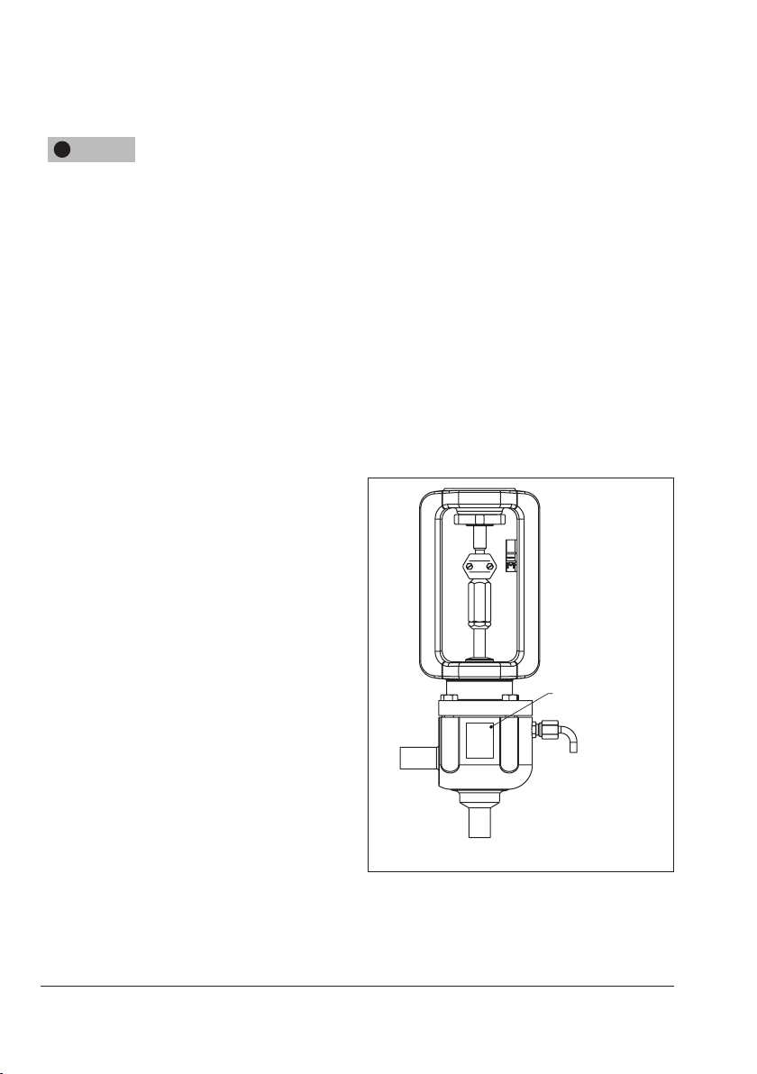
2 Markings on the control
valve
2.1 Body inscription
The details on the valve version are lasered
onto the front and back of the valve body
(see Fig.1). No nameplate is used.
2.2 Actuator nameplate
See associated actuator documentation.
Body
inscription
2.3 Material number
The seat and plug of the valves have an article number written on them. Specifying this
article number, you can contact us to nd out
which material is used.
10 EB 8048-2/-3 EN
Fig.1: Body inscription
Page 11
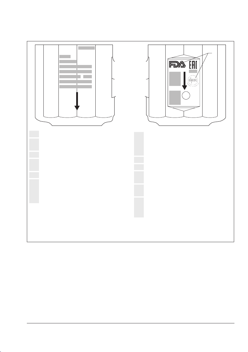
Safety instructions and measures
1SAMSON
2
3
4
5
6
8
9
7
1 Device modication index
2 Valve size:
DIN: DN · ANSI: NPS
3 Body material
4 Perm. operating gauge pressure at 20°C
bar/psi
5 Max. operating temperature °C/°F
6 Flow coefcient:
· C
K
V
V
Characteristic:
% = Equal percentage · L = Linear
10
12
11
F
SAMSON
13
Made in
France
7 Seat-plug seal:
ME: metal
PK: soft seal with PEEK
PT: soft seal with PTFE
8 Serial number
9 Conguration ID
10 Compliance with food industry require-
ments
11 CE marking or "Art. 4, Abs. 3" (PED
2014/68/EU)
12 If applicable, EAC mark including month
and year of production
13 SAMSON material marking
Fig.2: Information on the valve body
EB 8048-2/-3 EN 11
Page 12

Design and principle of operation
3 Design and principle of oper-
ation
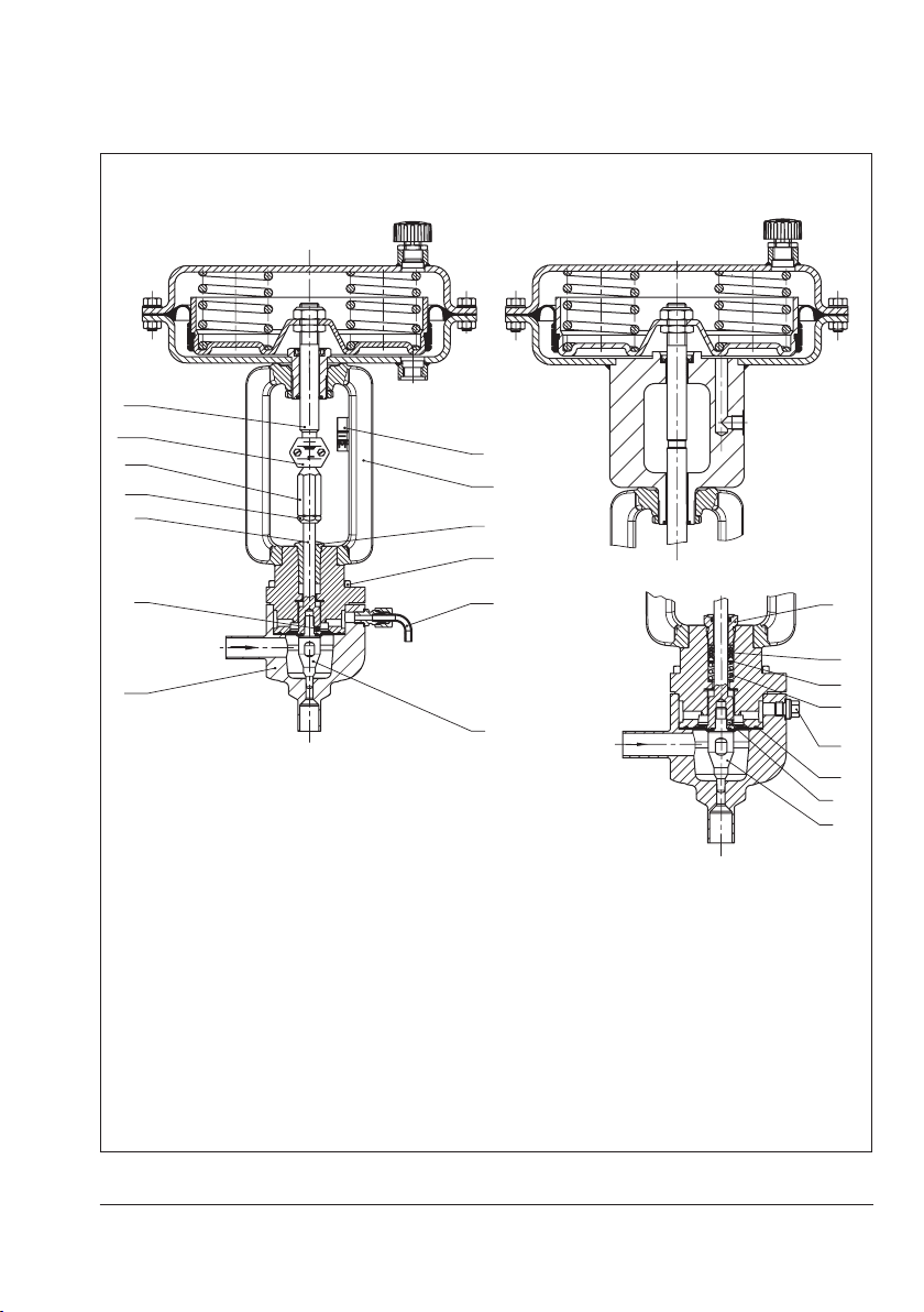
The Type3349 Angle Valve is preferably
combined with a SAMSON Type3271 or
Type3277 Pneumatic Actuator (see Fig.3)
as well as the Type3379 Pneumatic Actuator
(see Fig.4). The valve comes with welding
ends as standard. The valve is suitable for
aseptic applications and is designed without
any cavities.
The process medium ows through the valve
in the ow-to-close direction as indicated by
the arrow. The position of the valve plug determines the ow rate across the cross-sectional area of ow released between plug
and lathed seat.
In the standard version, the plug stem is
sealed by the USP-VI diaphragm. In the special version, an additional backup packing is
used (see Fig.5). The test connection allows
the diaphragm to be monitored for leakage.
In the version with backup packing, the test
connection is sealed by a stopper. The stopper must be replaced with a suitable leakage
indicator (e.g. a contact pressure gauge, an
outlet to an open vessel or an inspection
glass) when the valve is installed. The test
connection of valves without a backup packing is tted with a pipe elbow to allow the
safe drainage of any medium that escapes.
When combined with the Type3271 or
Type3277 Actuator, the actuator stem and
plug stem are connected using stem connector clamps (A26/27). When combined with
the Type3379 Actuator, the actuator stem
and plug stem are screwed together.
3.1 Fail-safe positions
The fail-safe position depends on the mounted actuator. Depending on how the compression springs are arranged in the pneumatic actuator, the valve has two different
fail-safe positions:
Actuator stem extends (FA)
When the signal pressure is reduced or the
air supply fails, the springs move the actuator stem downward and close the valve. The
valve opens when the signal pressure is increased enough to overcome the force exerted by the springs.
Actuator stem retracts (FE)
When the signal pressure is reduced or the
air supply fails, the springs move the actuator stem upwards and open the valve. The
valve closes when the signal pressure is increased enough to overcome the force exerted by the springs.
Tip
The direction of action of the Type3271 and
Type3277 Pneumatic Actuator can be reversed, if required. Refer to the mounting
and operating instructions of the pneumatic
actuator:
uEB8310‑X for Type3271 and Type3277
12 EB 8048-2/-3 EN
Page 13
Design and principle of operation
40
A
5
23
24
36
Valve with Type 3271 Actuator Type3277 Actuator
A7
26
10
13
3
6
7
20
5
34
1
2
Valve with packing
1 Body
2 Plug
3 Plug stem
5 Threaded bushing or stem
seal
6 Threaded pin
7 Travel indicator scale
Fig.3: Type3349 Valve for combination with a Type3271 or Type3277 Actuator
EB 8048-2/-3 EN 13
10 Stem connector nut
13 Lock nut
15 Spring
19 Washer
20 Flange
23 V-ring packing
24 USP-VI diaphragm
34 Hex screw
36 Screw plug (test
connection) or nipple
(pipe)
40 Pipe
A7 Actuator stem
A26 Stem connector clamps
19
15
6
2
Page 14
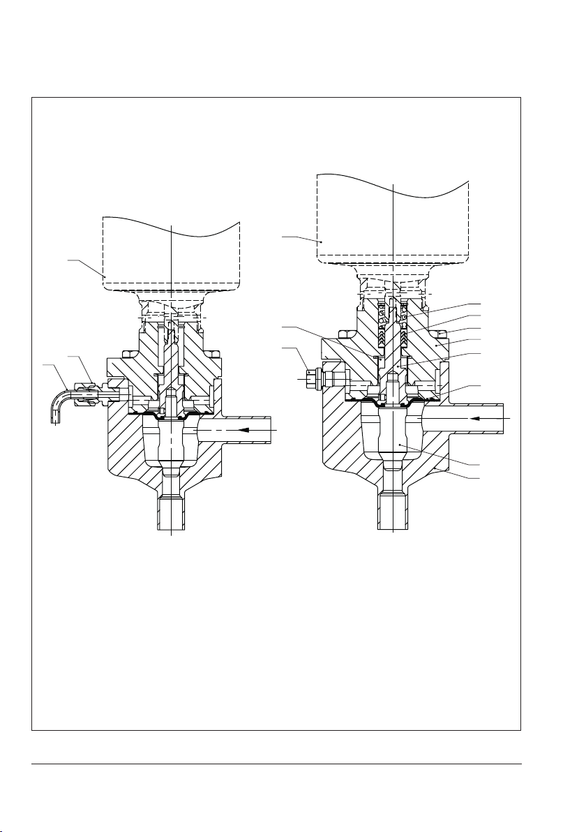
Design and principle of operation
40
Version without packing
A
36
A
41
36
Version with packing
15
23
34
20
3
1 Body
2 Plug
3 Plug stem
15 Spring
20 Valve bonnet
23 V-ring packing
24 USP-VI diaphragm
34 Hex screw
36 Screw plug (test connection) or
nipple (pipe)
40 Pipe
41 Bearing
Fig.4: Type3349 Valve for combination with a Type3379 Actuator
14 EB 8048-2/-3 EN
24
2
1
Page 15
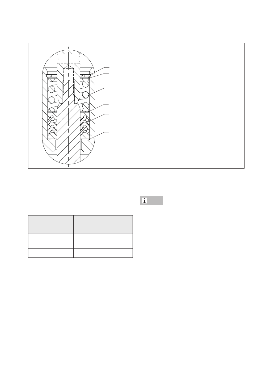
42
23
19
15
19
19
Design and principle of operation
Fig.5: Detailed view of backup packing
15 Spring
19 Washer
23 V-ring packing
42 Snap ring
3.2 Versions
Î Observe the maximum permissible actu-
ator force.
Micro-ow valve
The Type3349 Valve is also available as a
micro-ow valve.
With actuator
Type3271/
3277
Type3379 8 to 25 ¼ to 1
Valve size
DN NPS
8 to 25 ¼ to 1
Actuators
In these instructions, the preferable combination with a Type3271, Type3277 or
Note
If the travel range of the actuator is larger
than the travel range of the valve, the spring
assembly in the actuator must be preloaded
so that the travel ranges match. See associated actuator documentation.
Valve accessories
A Type3724 Positioner is frequently used
when the Type3349 Angle is combined with
a Type3379 Pneumatic Actuator.
Type3379 Pneumatic Actuator is described.
The pneumatic actuator can be replaced by
another pneumatic actuator in a different
size, but with the same travel.
EB 8048-2/-3 EN 15
Page 16
Design and principle of operation
3.3 Technical data
The inscription on the valve body and the
nameplate on the actuator provide information on the control valve version. See section2.1 and the actuator documentation.
Note
More information is available in Data Sheets
uT8048‑2 and uT8048‑3.
Compliance
The Type3349 Valve bears both the CE and
EAC marks of conformity.
·
Temperature range
Depending on the version, the control valve
is designed for a temperature range from 0
to +160°C (32 to 320°F).
Leakage class
Depending on the version, the following
leakage class applies:
Seal (7 on
nameplate)
Leakage class
(according to
IEC60534-4 or
ANSI/FCI70-2)
ME PT, PK
Min. IV VI
Noise emission
SAMSON is unable to make general
statements about noise emission as it
depends on the valve version, plant facilities,
and process medium.
!
WARNING
Risk of hearing loss or deafness due to loud
noise.
Wear hearing protection when working near
the valve.
16 EB 8048-2/-3 EN
Page 17
Design and principle of operation
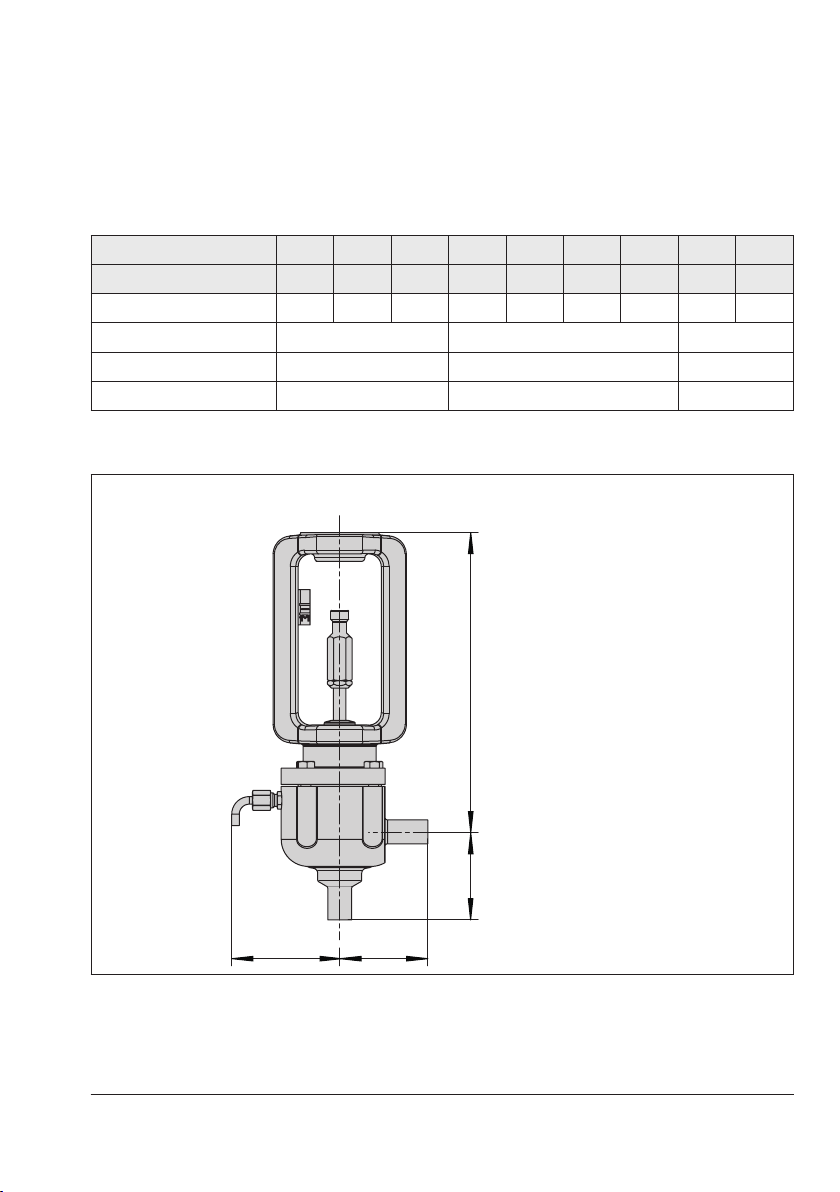
Dimensions and weights
Table1: Dimensions of Type3349 Angle Valve for mounting onto Type3271 and
Type3277 Actuators
DN 15 20 25 32 40 50 65 80 100
NPS ½ ¾ 1 1¼ 1½ 2 2½ 3 4
H1 mm 238 241 244 276 279 285 293 348 360
1)
L1
mm 70 105 150
G mm 86 113 144
2)
Weight
1)
Length with welding ends (DIN version). Dimensions of other connections and versions uT8048-2
2)
Weight with welding ends
kg 6 16 40
Dimensional drawing
H1
L1
Type3349 for mounting onto
G
L1
Type3271 and Type3277 Actuators
EB 8048-2/-3 EN 17
Page 18

Design and principle of operation
Table2: Dimensions of Type3349 Angle Valve for mounting onto Type3379 Actuator
DN 15 20 25 32 40 50
NPS ½ ¾ 1 1¼ 1½ 2
Rated travel mm 7.5 15
H1 mm 68 101
1)
L1
mm 70 105
G mm 84 112
2)
Weight
1)
Length with welding ends (dimensions of other connections uT8048-3)
2)
Weight with welding ends
kg 3.7 13
Table3: Dimensions of Type3349 as micro‑ow valve for mounting onto Type3379 Actua-
tor
DN 8 10 15 20 25
NPS – ¼ ½ ¾ 1
Rated travel mm 7.5
1)
L1
DIN11866, Series A
H1 mm 61 61 65 65 70
G mm 83
2)
Weight
DIN11866, SeriesB
H1 mm 61 65 65 70 70
G mm 83
2)
Weight
DIN11866, Series C
H1 mm
G mm 83
2)
Weight
1)
Length with welding ends (dimensions of other connections uT8048-3)
2)
Weight with welding ends
mm 50
kg 1
kg 1
61 61 65 70
–
kg 1
18 EB 8048-2/-3 EN
Page 19

Dimensional drawings
L1 H1
Design and principle of operation
H1
L1
L1 G
Type3349 for mounting onto Type3379
Actuator · Standard version
G L1
Type3349 for mounting onto Type3379
Actuator · Micro-ow valve version
EB 8048-2/-3 EN 19
Page 20

Measures for preparation
4 Measures for preparation
After receiving the shipment, proceed as follows:
1. Check the scope of delivery. Compare
the shipment received against the delivery note.
2. Check the shipment for transportation
damage. Report any damage to
SAMSON and the forwarding agent
(refer to delivery note).
4.1 Unpacking
Note
Do not remove the packaging until immediately before installing the valve into the pipeline.
Proceed as follows to lift and install the
valve:
1. Remove the packaging from the valve.
2. Dispose of the packaging in accordance
with the valid regulations.
!
NOTICE
Risk of valve damage due to foreign particles entering the valve.
The protective caps tted on the valve's inlet
and outlet prevent foreign particles from entering the valve and damaging it.
Do not remove the protective caps until immediately before installing the valve into the
pipeline.
4.2 Transporting and lifting
!
DANGER
Hazard due to suspended loads falling.
Stay clear of suspended or moving loads.
!
WARNING
Risk of lifting equipment tipping and risk of
damage to lifting accessories due to exceeding the rated lifting capacity.
− Only use approved lifting equipment and
accessories whose minimum lifting
capacity is higher than the weight of the
valve (including actuator, if applicable).
− Refer to section3.3 and the corresponding
data sheets (uT8048‑2 and uT8048‑3)
for the weights.
!
WARNING
Risk of personal injury due to control valve
tipping.
− Observe the valve's center of gravity.
− Secure the valve against tipping over or
turning.
!
NOTICE
Risk of valve damage due to incorrectly attached slings.
− When lifting the control valve, make sure
that the slings attached to the valve body
bear the entire load.
− Do not attach slings to the pipe elbow.
− Do not attach load‑bearing slings to the
valve accessories.
20 EB 8048-2/-3 EN
Page 21

Measures for preparation
− Observe lifting instructions (see sec-
tion4.2.2).
Tip
SAMSON's After‑sales Service department
can provide more detailed transport and lift-
ing instructions on request.
4.2.1 Transporting
The control valve can be transported using
lifting equipment (e.g. crane or forklift).
Î Leave the control valve in its transport
container or on the pallet to transport it.
Î Observe the transport instructions.
Transport instructions
− Protect the control valve against external
inuences (e.g. impact).
− Do not damage the corrosion protection
(paint, surface coatings). Repair any
damage immediately.
− Protect the control valve against moisture
and dirt.
− Observe the permissible temperature
range (see section3.3).
− Make sure the slings can be removed
from the valve once it has been installed
into the pipeline.
− Prevent the control valve from tilting or
tipping.
− Do not leave loads suspended when in-
terrupting work for longer periods of
time.
− Make sure that the axis of the pipeline is
always horizontal during lifting and the
axis of the plug stem is always vertical.
− Make sure that the additional sling be-
tween the lifting eyelet and rigging
equipment (hook, shackle etc.) does not
bear any load when lifting valves. The
sling only protects the control valve from
tilting while being lifted. Before lifting the
control valve, tighten the sling.
4.2.2 Lifting
Lifting equipment (e.g. crane or forklift) can
be used to lift heavy control valves.
Lifting instructions
− Secure slings against slipping.
EB 8048-2/-3 EN 21
Page 22

Measures for preparation
Lifting points on the control valve
Fig.6: Type3349‑1 without lifting eyelet Fig.7: Type3349‑1 with lifting eyelet
Fig.8: Type3349‑7 without lifting eyelet Fig.9: Type3349/3379
22 EB 8048-2/-3 EN
Page 23

Measures for preparation
Lifting the control valve
1. With Type3271 or 3277: carefully
guide two slings around the ange and
attach them to the rigging equipment of
the crane or forklift (see Fig.6, Fig.7,
and Fig.8). Make sure that the actuator
stem and valve accessories are not damaged.
For actuator versions with lifting eyelet,
attach an additional sling to the lifting
eyelet of the actuator and to the rigging
equipment of the crane or forklift (see
Fig.7).
With Type3379: carefully guide two
slings around the actuator. Secure the
slings against slipping by using a connector (see Fig.9).
2. Carefully lift the control valve. Check
whether the lifting equipment and accessories can bear the weight.
3. Move the control valve at an even pace
to the site of installation.
4. Install the valve into the pipeline (see section5.2.2).
5. After installation into the pipeline: depending on the type of connection (e.g.
welding joint, anged joint, etc.) check
whether the valve in the pipeline holds.
6. Remove slings.
4.3 Storage
!
NOTICE
Risk of valve damage due to improper storage.
− Observe storage instructions.
− Avoid long storage times.
− Contact SAMSON in case of different stor-
age conditions or long storage periods.
Note
We recommend regularly checking the control valve and the prevailing storage conditions during long storage periods.
Storage instructions
− Protect the control valve against external
inuences (e.g. impact).
− Do not damage the corrosion protection
(paint, surface coatings). Repair any
damage immediately.
− Protect the control valve against moisture
and dirt. Store it at a relative humidity of
less than 75%. In damp spaces, prevent
condensation. If necessary, use a drying
agent or heating.
− Make sure that the ambient air is free of
acids or other corrosive media.
− Observe the permissible temperature
range (see section3.3).
− Do not place any objects on the control
valve.
EB 8048-2/-3 EN 23
Page 24

Measures for preparation
Special storage instructions for elastomers
Elastomer, e.g. actuator diaphragm
− To keep elastomers in shape and to pre-
vent cracking, do not bend them or hang
them up.
− We recommend a storage temperature of
15°C for elastomers.
− Store elastomers away from lubricants,
chemicals, solutions, and fuels.
Tip
SAMSON's After‑sales Service department
can provide more detailed storage instructions on request.
4.4 Preparation for installation
Proceed as follows:
Î Flush the pipelines.
Note
The plant operator is responsible for clean-
ing the pipelines in the plant.
Î Check the valve for damage.
Î Check to make sure that the type
designation, valve size, material,
pressure rating, and temperature range
of the valve match the plant conditions
(size and pressure rating of the pipeline,
medium temperature etc.).
Î Check any mounted pressure gauges to
make sure they function.
Î When the valve and actuator are al-
ready assembled, check the tightening
torques of the bolted joints (uAB0100).
Components may loosen during transport.
Î Check the valve to make sure it is clean.
!
NOTICE
Risk of contamination of the process medium
through the use of unsuitable lubricant and/
or contaminated tools and components.
− Keep the valve and the tools used free from
solvents and grease.
− Make sure that only suitable lubricants are
used.
24 EB 8048-2/-3 EN
Page 25

EB 8048-2/-3 EN 25
Page 26

Mounting and start-up
5 Mounting and start-up
SAMSON valves are delivered ready for
use. In special cases, the valve and actuator
are delivered separately and must be assembled on site. The procedure to mount and
start up the valve are described in the following.
!
NOTICE
Risk of valve damage due to excessively high
or low tightening torques.
Observe the specied torques on tightening
control valve components. Excessively tightened torques lead to parts wearing out
quicker. Parts that are too loose may cause
leakage.
Observe the specied tightening torques
(uAB0100).
!
NOTICE
Risk of valve damage due to the use of unsuitable tools.
Only use tools approved by SAMSON
(uAB0100).
5.1 Mounting the actuator onto the valve
Note
− Remove the mounted actuator before
mounting the other actuator (see associated actuator documentation).
− Preloading the actuator springs increases
the thrust of a pneumatic actuator and reduces the travel range of the actuator (see
associated actuator documentation).
5.1.1 Version with Type3271
or Type3277 Actuator
Refer to Fig.10
Proceed as described in the actuator docu-
mentation if the valve and actuator have not
been assembled by SAMSON.
Î Make sure that the dimension x from the
bottom of the actuator stem to the bottom
of the actuator case is correctly adjusted
(see Table4).
!
NOTICE
Risk of contamination of the process medium
through the use of unsuitable lubricant and/
or contaminated tools and components.
− Keep the valve and the tools used free from
solvents and grease.
− Make sure that only suitable lubricants are
used.
26 EB 8048-2/-3 EN
Page 27

x
Table4: Dimension x
Version
Micro-ow
valve
Standard
Valve size
DN NPS
8 to 25 ¼ to 1 67.5
15 to 25 ½ to 1 67.5
32 to 65 1¼ to 2½ 75
80 and
100
Mounting and start-up
Dimension
x in mm
3 and 4 90
Fig.10: Dimension x
5.1.2 Version with Type3379
Actuator
Refer to Fig.11
2. Lift the valve bonnet (20) together with
the plug (2), plug stem (3), and diaphragm (24) off the body (1).
3. Screw the actuator (A) onto the valve
bonnet (20).
Note
To prevent the actuator stem from rotating, a
locking pin with 3.5mm diameter is required. The locking pin (item no. 1281‑
0066) can be ordered from SAMSON.
1. Undo the screws (34) on the valve
bonnet (20).
4. "Actuator stem extends" fail-safe ac-
tion: guide the locking pin (Ø 3.5mm)
through the hole located in the bottom
actuator section and the actuator stem.
"Actuator stem retracts" fail-safe action:
apply 6bar signal pressure to the actuator. Guide the locking pin (Ø 3.5mm)
through the hole located in the bottom
actuator section and the actuator stem.
EB 8048-2/-3 EN 27
Page 28

Mounting and start-up
34
20
24
5. Unscrew the plug stem (3) together with
diaphragm (24) and plug (2) from the
actuator stem.
6. Remove locking pin.
A
7. Place the actuator and valve bonnet (20)
together with the plug (2), plug stem (3),
and diaphragm (24) onto the body (1).
8. Tighten the screws (34) on the valve bonnet (20) gradually in a crisscross pattern.
Observe tightening torques.
3
9. For further instructions concerning
Type3379 Actuator (pneumatic connections, alignment of the actuator, etc.)
uEB8315.
5.2 Installing the valve into the
2
1
pipeline
5.2.1 Checking the installation
conditions
1 Body
2 Plug
3 Plug stem
20 Valve bonnet
Fig.11: Assembling Type3349 Valve and
Type3379 Actuator
24 Diaphragm
34 Screw
A Actuator
Pipeline routing
The inlet and outlet lengths vary depending
on the process medium. To ensure the control
valve functions properly, follow the installation instructions given below:
Î Observe the inlet and outlet lengths (see
Table5). Contact SAMSON if the valve
conditions or state of the medium process
deviate.
Î Install the valve free of stress and with the
least amount of vibrations as possible. If
necessary, attach supports to the valve.
Î Install the valve allowing sufcient space
to remove the actuator and valve or to
28 EB 8048-2/-3 EN
Page 29

Mounting and start-up
Q
perform service and repair work on
them.
Mounting position
Generally, we recommend installing the
valve with the actuator upright and on top of
the valve.
In the following versions, the valve must be
installed with the actuator on top:
− For valves that are intended to be free of
cavities
Î Contact SAMSON if the mounting posi-
tion is not as specied above.
Support or suspension
Depending on the valve version and mounting position, the control valve and pipeline
Table5: Inlet and outlet lengths
a x DN
must be supported or suspended. The plant
engineering company is responsible in this
case.
!
NOTICE
Premature wear and leakage due to insufcient support or suspension.
In the following versions, the control valve
must be supported or suspended:
− Valves that are not installed with the actua-
tor in the upright position on top of the
valve.
Attach a suitable support or suspension to
the valve.
Q Flow rate
a Inlet length
b Outlet length
b x DN
State of process
medium
Gas Ma≤0.3 2 4
Vapor Ma≤0.3
Liquid
1)
No saturated steam
Valve conditions
1)
Free of cavitation/w<10m/s 2 4
Cavitation producing noise/w≤3m/s 2 4
Cavitation producing noise/3<w<5m/s 2 10
Inlet
length a
2 4
Outlet
length b
EB 8048-2/-3 EN 29
Page 30

Mounting and start-up
Vent plug
Vent plugs are screwed into the exhaust air
ports of pneumatic and electropneumatic devices. They ensure that any exhaust air that
forms can be vented to the atmosphere (to
avoid excess pressure in the device). Furthermore, the vent plugs allow air intake to prevent a vacuum from forming in the device.
Î Locate the vent plug on the opposite side
to the workplace of operating personnel.
Î On mounting valve accessories, make
sure that they can be operated from the
workplace of the operating personnel.
Note
The workplace of operating personnel is the
location from which the valve, actuator, and
any mounted valve accessories can be accessed to operate them.
5.2.2 Installing the control valve
1. Close the shut-off valve in the pipeline
while the valve is being installed.
2. Remove any protective caps from the
valve ports before installing the valve.
3. Lift the valve using suitable lifting equip-
ment to the site of installation (see section4.2). Observe the ow direction
through the valve. The arrow on the
valve indicates the direction of ow.
4. Completely retract the actuator stem to
protect the plug from sparks during welding.
5. Weld the valve free of stress into the
pipeline.
6. Depending on the eld of application,
allow the valve to cool down or heat up
to reach ambient temperature before
start up.
7. Slowly open the shut-off valve in the
pipeline after the valve has been installed.
!
NOTICE
Risk of valve damage due to a sudden pressure increase and resulting high ow velocities.
Slowly open the shut‑off valve in the pipeline
during start‑up.
8. Check the valve to ensure it functions
properly.
5.3 Preparing for operation
Proceed as follows:
Î Flush the pipelines.
Î Check the valve to make sure it is clean.
!
NOTICE
Risk of contamination of the process medium
through the use of unsuitable lubricant and/
or contaminated tools and components.
− Keep the valve and the tools used free from
solvents and grease.
− Make sure that only suitable lubricants are
used.
30 EB 8048-2/-3 EN
Page 31

Mounting and start-up
5.4 Quick check
SAMSON valves are delivered ready for
use. To test the valve's ability to function, the
following quick checks can be performed:
Tight shut-off
1. Close the valve.
2. Slowly open the shut-off valve in the
pipeline.
!
NOTICE
Risk of valve damage due to a sudden pressure increase and resulting high ow velocities.
Slowly open the shut‑off valve in the pipeline
during start‑up.
3. Check the valve for leakage (visual inspection).
Travel motion
The movement of the actuator stem must be
linear and smooth.
Î Open and close the valve, observing the
movement of the actuator stem.
Î Apply the maximum and minimum con-
trol signals to check the end positions of
the valve.
Î Type3349-1 and Type3349-7: check
the travel reading at the travel indicator
scale.
Pressure test
During the pressure test, make sure the following conditions are met:
− Retract the plug stem to open the valve.
− Observe the maximum permissible pres-
sure for valve and plant.
Note
The plant operator is responsible for per-
forming the pressure test. SAMSON's After‑sales Service department can support you
to plan and perform a pressure test for your
plant.
Fail-safe position
Î Shut off the signal pressure line.
Î Check whether the valve moves to the
fail-safe position.
EB 8048-2/-3 EN 31
Page 32

Operation
6 Operation
Immediately after completing mounting and
start-up (see section5), the valve is ready for
use.
!
WARNING
Type3349‑1 and Type3349‑7: crush hazard arising from moving parts (actuator and
plug stem).
Do not insert hands or ngers into the yoke
while the valve is in operation.
!
WARNING
Risk of personal injury when the actuator
vents.
Wear eye protection when working in close
proximity to the control valve.
!
WARNING
Risk of burn injuries due to hot or cold components and pipelines.
Depending on the process medium, valve
components, and pipelines may get very hot
or cold and cause burn injuries.
Wear protective clothing and safety gloves.
− Wear protective clothing (eye protection,
safety gloves) when working in close proximity to the control valve.
!
WARNING
Risk of personal injury due to pressurized
components and process medium escaping
under pressure.
Do not loosen the screw of the test connection while the valve is in operation.
!
NOTICE
Risk of impairment of aseptic or hygienic
service.
In the version with backup packing, the test
connection is sealed by a stopper. To guarantee aseptic or hygienic service, connect a
leakage detection device to the test connection.
!
NOTICE
Operation disturbed by a blocked actuator
or plug stem.
Do not impede the movement of the actuator
or plug stem by inserting objects into their
path.
!
WARNING
!
Risk of personal injury due to process
medium escaping under pressure.
− Align the pipe elbow to ensure that any es-
caping process medium does not hit operating personnel.
32 EB 8048-2/-3 EN
NOTICE
Diaphragm damage through the use of an
incompressible medium.
Closing the valve when the shut‑off valves
upstream and downstream of the valve are
closed may lead to the diaphragm rupturing
Page 33

in plants with liquid media owing through
them.
Only close the valve after opening the shut‑
off valves upstream and downstream of the
control valve.
6.1 CIP (cleaning-in-place)
CIP can be performed with commonly used
cleaning uids.
Î Observe the applicable hygiene regula-
tions.
6.2 SIP (sterilization-in-place)
SIP can be performed using steam at a temperature up to 180°C for a maximum of
30minutes.
Î Observe the applicable hygiene regula-
tions.
Operation
EB 8048-2/-3 EN 33
Page 34

Servicing
7 Servicing
The control valve is subject to normal wear,
especially at the diaphragm, seat, plug, and
packing. Depending on the operating conditions, check the valve at regular intervals to
prevent possible failure before it can occur.
Tip
SAMSON's After‑sales Service department
can support you to draw up an inspection
plan for your plant.
!
DANGER
Risk of bursting in pressure equipment.
Control valves and pipelines are pressure
equipment. Improper opening can lead to
valve components bursting.
− Before starting any work on the control
valve, depressurize all plant sections concerned as well as the valve.
− Drain the process medium from all the
plant sections concerned as well as the
valve.
− Wear personal protective equipment.
!
WARNING
Risk of personal injury due to residual process medium in the valve.
While working on the valve, residual process
medium can escape and, depending on its
properties, may lead to personal injury, e.g.
(chemical) burns.
Wear protective clothing, safety gloves, and
eyewear.
!
WARNING
Risk of burn injuries due to hot or cold components and pipeline.
Valve components and the pipeline may become very hot or cold. Risk of burn injuries.
− Allow components and pipelines to cool
down or heat up.
− Wear protective clothing and safety gloves.
!
NOTICE
Risk of valve damage due to incorrect
servicing or repair.
Service and repair work must only be
performed by trained staff.
!
NOTICE
Risk of valve damage due to excessively high
or low tightening torques.
Observe the specied torques on tightening
control valve components. Excessively tightened torques lead to parts wearing out
quicker. Parts that are too loose may cause
leakage.
Observe the specied tightening torques
(uAB0100).
!
NOTICE
Risk of valve damage due to the use of unsuitable tools.
Only use tools approved by SAMSON
(uAB0100).
34 EB 8048-2/-3 EN
Page 35

Servicing
!
NOTICE
Risk of contamination of the process medium
through the use of unsuitable lubricant and/
or contaminated tools and components.
− Keep the valve and the tools used free from
solvents and grease.
− Make sure that only suitable lubricants are
used (uAB0100).
Note
The control valve was checked by SAMSON
before it left the factory.
− Certain test results (seat leakage and leak
test) certied by SAMSON lose their validity when the valve body or actuator housing is opened.
− The product warranty becomes void if
service or repair work not described in
these instructions is performed without
prior agreement by SAMSON's After‑sales
Service department.
− Only use original spare parts by
SAMSON, which comply with the original
specications.
Checking the extent of servicing
Î Check wear at seat and plug. Replace
the damaged plug (see section7.1.2 or
7.2.2).
Î Check the diaphragm for damage (e.g.
cracks, milky coloring at the bends). Replace the damaged diaphragm (see section7.1.2 or 7.2.2).
Î If the valve leaks even if the diaphragm
is intact, check the tightening torque of
the joint between plug and plug stem as
well as body and bonnet/ange.
Preparing the valve for servicing
1. Put the control valve out of operation (see
section9.1).
2. Remove the valve from the pipeline (see
section9.2).
7.1 Version with Type3271 or
Type3277 Actuator
7.1.1 Replacing the packing
1. Remove the actuator from the valve. See
associated actuator documentation.
2. Undo the hex screws (34).
3. Lift the ange (20) together with the plug
stem (3), plug (2), and diaphragm (24)
off the body (1).
4. Unscrew the threaded bushing (5).
5. Pull the plug (2) together with plug stem
(3) and diaphragm (24) out of the ange
(20).
6. Pull all the packing parts out of the packing chamber using a suitable tool. Renew
the damaged parts and carefully clean
the packing chamber.
7. Push the plug (2) together with plug stem
(3) and diaphragm (24) into the ange
(20).
8. Carefully slide the packing parts over the
plug stem into the packing chamber using a suitable tool.
9. Tighten the threaded bushing (5).
EB 8048-2/-3 EN 35
Page 36

Servicing
40
A
5
23
24
36
A7
26
10
13
3
6
Valve with Type 3271 Actuator Type3277 Actuator
7
20
5
34
1
2
Valve with packing
1 Body
2 Plug
3 Plug stem
5 Threaded bushing
6 Threaded pin
7 Travel indicator scale
10 Stem connector nut
Fig.12: Type3349 Angle Valve for Type3271 and Type3277 Actuators
36 EB 8048-2/-3 EN
13 Lock nut
15 Spring
19 Washer
20 Flange
23 V-ring packing
24 Diaphragm
34 Hex screw
36 Screw plug (test
connection) or nipple
(pipe)
40 Pipe
A7 Actuator stem
A26 Stem connector clamps
19
15
6
2
Page 37

Servicing
10. Place the ange (20) together with the
plug stem (3), plug (2), and diaphragm
(24) onto the body (1).
11. Apply a suitable lubricant to the hex
screws (34).
12. Tighten the hex screws (34) on the ange
(20) gradually in a crisscross pattern.
Observe tightening torques.
13. Mount actuator. See associated actuator
documentation.
14. Adjust lower or upper signal bench
range. See associated actuator documentation.
7.1.2 Replacing the dia-
phragm and plug
1. Remove the actuator from the valve. See
associated actuator documentation.
2. Undo the hex screws (34).
3. Lift the ange (20) together with the plug
stem (3), plug (2), and diaphragm (24)
off the body (1).
4. Pull the plug (2) together with plug stem
(3) and diaphragm (24) out of the ange
(20).
For version with packing: replace the
packing (see section7.1.1).
5. Unscrew the threaded pin (6).
6. Unscrew the plug stem (3) from the plug
(2).
7. Remove diaphragm (24).
8. Apply a suitable lubricant to the thread
of the plug stem (3).
9. Screw a new plug (2) onto the plug stem
(3) using a suitable tool. Observe tightening torques.
10. Mark the side mounting position.
11. Unscrew the plug stem (3) from the plug
(2).
12. Insert a new diaphragm (24) into the
new plug.
13. Screw the new plug (2) back onto the
plug stem (3) again using a suitable tool.
Align the plug stem with the mounted position mark made earlier. To do this,
clamp the plug into a suitable clamping
xture and pull it with a suitable tool.
14. Remove the mounting position mark.
15. Secure the plug (2) with threaded pin
(6).
16. Check the concentricity of the plug (see
section7.3).
17. Push the plug (2) together with plug stem
(3) and diaphragm (24) into the ange
(20).
18. Place the ange (20) together with the
plug stem (3), plug (2), and diaphragm
(24) onto the body (1).
19. Apply a suitable lubricant to the hex
screws (34).
20. Tighten the hex screws (34) on the ange
(20) gradually in a crisscross pattern until the valve bonnet touches the body
ange.
Note
Greater deformation forces are required for
new diaphragms (in comparison to already
EB 8048-2/-3 EN 37
Page 38

Servicing
40
A
41
36
15
23
34
20
A
3
36
24
2
1
1 Body
2 Plug
3 Plug stem
15 Spring
20 Valve bonnet
23 V-ring packing
34 Hex screw
36 Screw plug (test connection) or nip-
ple (pipe)
40 Pipe
41 Bearing
A Actuator
24 Diaphragm
Fig.13: Type3349 Angle Valve for Type3379 Actuator · With additional packing (left) and with pipe
(right)
38 EB 8048-2/-3 EN
Page 39

Servicing
23
installed diaphragms). We recommend
shaping the new diaphragms beforehand using conventional hex screws:
− Tighten the conventional hex screws as de-
scribed in step 20.
− Replace the conventional hex screws with
the existing hex screws (34).
− Tighten the hex screws (34) as described in
step 20.
21. Mount actuator. See associated actuator
documentation.
22. Adjust lower or upper signal bench
range. See associated actuator documentation.
Fig.14: Detailed view of backup packing
42
19
7.2 Version with Type3379
Actuator
Note
To prevent the actuator stem from rotating, a
locking pin with 3.5mm diameter is required. The locking pin (item no. 1281‑
0066) can be ordered from SAMSON.
7.2.1 Replacing the packing
1. Undo the screws (34) on the valve
bonnet (20).
2. Lift the actuator (A) and valve bonnet
(20) together with the plug stem (3), plug
(2), and diaphragm (24) off the body
(1).
15
19
15 Spring
19
19 Washer
23 V-ring packing
42 Snap ring
EB 8048-2/-3 EN 39
Page 40

Servicing
3. "Actuator stem extends" fail-safe action: guide the locking pin (Ø 3.5mm)
through the hole located in the bottom
actuator section and the actuator stem.
"Actuator stem retracts" fail-safe action:
apply 6bar signal pressure to the actuator. Guide the locking pin (Ø 3.5mm)
through the hole located in the bottom
actuator section and the actuator stem.
4. Unscrew the plug stem (3) together with
plug (2) and diaphragm (24) from the
actuator stem and pull it out of the valve
bonnet (20).
5. Unscrew the actuator (A) from the valve
bonnet (20).
6. Remove locking pin.
7. Compress the packing using a suitable
tool and remove the snap ring (42).
8. Pull all the packing parts out of the packing chamber using a suitable tool. Renew
the damaged parts and carefully clean
the packing chamber.
9. Check the plug and diaphragm for damage. Replace them, if necessary (see section7.2.2).
10. Push the plug (2) together with plug stem
(3) and diaphragm (24) into the valve
bonnet (20).
11. Carefully slide the packing parts over the
plug stem into the packing chamber using a suitable tool.
12. Compress the packing using a suitable
tool and insert the snap ring (42).
13. Screw the actuator (A) onto the valve
bonnet (20).
14. "Actuator stem extends" fail-safe ac-
tion: guide the locking pin (Ø 3.5mm)
through the hole located in the bottom
actuator section and the actuator stem.
"Actuator stem retracts" fail-safe action:
apply 6bar signal pressure to the actuator. Guide the locking pin (Ø 3.5mm)
through the hole located in the bottom
actuator section and the actuator stem.
15. Apply a suitable lubricant to the actuator
stem.
16. Screw the plug stem (3) together with
plug (2) and diaphragm (24) onto the
actuator stem. Observe tightening
torques.
17. Remove locking pin.
18. Place the actuator and valve bonnet (20)
together with the plug stem (3), plug (2),
and diaphragm (24) onto the body (1).
19. Apply a suitable lubricant to the hex
screws (34).
20. Tighten the hex screws (34) on the valve
bonnet (20) gradually in a crisscross pattern. Observe tightening torques.
21. For version with Type3724 Positioner:
initialize the positioner (uEB8395).
7.2.2 Replacing the dia-
phragm and plug
Note
Before replacing the diaphragm and plug,
remove the valve from the plant.
40 EB 8048-2/-3 EN
Page 41

Servicing
1. Undo the screws (34) on the valve
bonnet (20).
2. Lift the actuator (A) and valve bonnet
(20) together with the plug stem (3), plug
(2), and diaphragm (24) off the body
(1).
3. "Actuator stem extends" fail-safe ac-
tion: guide the locking pin (Ø 3.5mm)
through the hole located in the bottom
actuator section and the actuator stem.
"Actuator stem retracts" fail-safe action:
apply 6bar signal pressure to the actuator. Guide the locking pin (Ø 3.5mm)
through the hole located in the bottom
actuator section and the actuator stem.
4. Unscrew the plug stem (3) together with
plug (2) and diaphragm (24) off the actuator stem and pull it out of the valve
bonnet (20).
5. Unscrew the actuator (A) from the valve
bonnet (20).
6. Remove locking pin.
For version with packing: replace the
packing (see section7.2.1).
7. Unscrew the threaded pin (6).
8. Unscrew the plug stem (3) from the plug
(2).
9. Remove diaphragm (24).
10. Apply a suitable lubricant to the thread
of the plug stem (3).
11. Screw a new plug (2) onto the plug stem
(3) using a suitable tool. Observe tightening torques.
12. Mark the side mounting position.
13. Unscrew the plug stem (3) from the plug
(2).
14. Insert a new diaphragm (24) into the
new plug.
15. Screw the new plug (2) back onto the
plug stem (3) again using a suitable tool.
Align the plug stem with the mounted position mark made earlier. To do this,
clamp the plug into a suitable clamping
xture and pull it with a suitable tool.
16. Remove the mounting position mark.
17. Secure the plug (2) with threaded pin
(6).
18. Check the concentricity of the plug (see
section7.3).
19. Push the plug (2) together with plug stem
(3) and diaphragm (24) into the valve
bonnet (20).
20. Apply a suitable lubricant to the thread
of the valve bonnet (20).
21. Screw the actuator (A) onto the valve
bonnet (20).
22. "Actuator stem extends" fail-safe ac-
tion: guide the locking pin (Ø 3.5mm)
through the hole located in the bottom
actuator section and the actuator stem.
"Actuator stem retracts" fail-safe action:
apply 6bar signal pressure to the actuator. Guide the locking pin (Ø 3.5mm)
through the hole located in the bottom
actuator section and the actuator stem.
23. Apply a suitable lubricant to the actuator
stem.
24. Screw the plug stem (3) together with
plug (2) and diaphragm (24) onto the
EB 8048-2/-3 EN 41
Page 42

Servicing
actuator stem. Observe tightening
torques.
25. Remove locking pin.
26. Place the actuator and valve bonnet (20)
together with the plug stem (3), plug (2),
and diaphragm (24) onto the body (1).
27. Apply a suitable lubricant to the hex
screws (34).
28. Tighten the hex screws (34) on the ange
(20) gradually in a crisscross pattern until the valve bonnet touches the body
ange.
Note
Greater deformation forces are required for
new diaphragms (in comparison to already
installed diaphragms). We recommend
shaping the new diaphragms beforehand using conventional hex screws:
− Tighten the conventional hex screws as de-
scribed in step 28.
− Replace the conventional hex screws with
the existing hex screws (34).
− Tighten the hex screws (34) as described in
step 28.
29. For version with Type3724 Positioner:
initialize the positioner (uEB8395).
7.3 Checking the concentricity
of the plug to the plug stem
2. Check the concentricity of the plug to the
plug stem. Observe the values listed in
Table6 and Table7.
3. If the concentricity deviates, use a suitable tool (e.g. plastic hammer) and hit
the plug until concentricity is achieved.
Tip
Instead of aligning the plug, the assembly
(consisting of plug stem, diaphragm, and
plug) can be ordered from SAMSON.
Table6: Concentricity of the plug · Version
with Type3271 or Type3277 Actuator
Valve size
DN NPS
8 to 25 ¼ to 1 0.01
15 to 25 ½ to 1 0.01
32 to 65 1¼ to 2½ 0.04
80 and 100 3 and 4 0.05
Max. deviation in
mm
Table7: Concentricity of the plug · Version
with Type3379 Actuator
Valve size
DN NPS
8 to 25 ¼ to 1 0.01
15 to 25 ½ to 1 0.01
32 to 50 1¼ to 2 0.04
Max. deviation in
mm
Before mounting the plug, the concentricity
of the plug to the plug stem must be checked.
1. Clamp the plug stem into a suitable
clamping device.
42 EB 8048-2/-3 EN
Page 43

Servicing
7.4 Preparation for return shipment
Defective valves can be returned to
SAMSON for repair.
Proceed as follows to return valves to
SAMSON:
1. Put the control valve out of operation (see
section9).
2. Decontaminate the valve. Remove any
residual process medium.
3. Fill in the Declaration on Contamination,
which can be downloaded from our
website at uwww.samson.de > Services
> Check lists for after sales service >
Declaration on Contamination.
4. Send the valve together with the lled-in
form to your nearest SAMSON subsidiary. SAMSON subsidiaries are listed on
our website at uwww.samson.de >
Contact.
7.5 Ordering spare parts and operating supplies
Contact your nearest SAMSON subsidiary
or the SAMSON After-sales Service department for information on spare parts, lubricants, and tools.
Spare parts
Details on spare parts are available on request.
Lubricant
Details on suitable lubricants can be found in
the document uAB0100.
Tools
Details on suitable tools can be found in the
document uAB0100.
EB 8048-2/-3 EN 43
Page 44

Malfunctions
8 Malfunctions
Depending on the operating conditions, check the valve at certain intervals to prevent possible failure before it can occur. Operators are responsible for drawing up an inspection plan.
Tip
SAMSON's After‑sales Service department can support you to draw up an inspection plan
for your plant.
8.1 Troubleshooting
Malfunction Possible reasons Recommended action
Actuator or plug stem does not
move on demand.
Actuator or plug stem does not
move through the whole range.
Increased ow through closed
valve (seat leakage)
Actuator is blocked. Check attachment.
Unblock the actuator.
Signal pressure too low Check the signal pressure.
Check the signal pressure line for
leakage.
Signal pressure too low Check the signal pressure.
Check the signal pressure line for
leakage.
Plug has become detached. Fasten plug and plug stem
together (see section7.1.2 and
7.2.2). Observe tightening
torques.
Dirt or other foreign particles
deposited between the seat and
plug.
Valve trim, particularly with soft
seat, is worn.
Shut off the section of the pipeline and ush the valve.
Replace plug (see section7.1.2
and 7.2.2) or contact
SAMSON's After-sales Service
department.
44 EB 8048-2/-3 EN
Page 45

Malfunctions
Malfunction Possible reasons Recommended action
The valve leaks to the
atmosphere (fugitive emissions).
The packing is defective. Replace packing (see
section7.1.1 and 7.2.1) or
contact SAMSON's After-sales
Service department.
Diaphragm not correctly
clamped into position.
Diaphragm damaged. Replace the diaphragm (see
Check that the diaphragm is
correctly seated. If necessary,
replace the diaphragm (see
section7.1.2 and 7.2.2).
Check the tightening torque of
the joint between plug and plug
stem.
Check the tightening torque of
the joint between body and
bonnet/ange.
section7.1.2 and 7.2.2).
Note
Contact SAMSON's After‑sales Service department for malfunctions not listed in the table.
8.2 Emergency action
Putting the valve back into operation after
a malfunction
Upon supply air or control signal failure, the
valve moves to its fail-safe position (see section3.1).
Î Slowly open the shut-off valves. Allow
the process medium to slowly ow into
the valve.
The plant operator is responsible for emergency action to be taken in the plant.
In the event of a valve malfunction:
1. Close the shut-off valves upstream and
downstream of the control valve to stop
the process medium from owing
through the valve.
2. Check the valve for damage. If necessary, contact SAMSON's After-sales Service department.
EB 8048-2/-3 EN 45
Page 46

Decommissioning and disassembly
9 Decommissioning and disas-
sembly
!
DANGER
Risk of bursting in pressure equipment.
Control valves and pipelines are pressure
equipment. Improper opening can lead to
valve components bursting.
− Before starting any work on the control
valve, depressurize all plant sections concerned as well as the valve.
− Drain the process medium from all the
plant sections concerned as well as the
valve.
− Wear personal protective equipment.
!
WARNING
Risk of personal injury due to residual process medium in the valve.
While working on the valve, residual process
medium can escape and, depending on its
properties, may lead to personal injury, e.g.
(chemical) burns.
Wear protective clothing, safety gloves, and
eyewear.
!
WARNING
Risk of burn injuries due to hot or cold components and pipeline.
Valve components and the pipeline may become very hot or cold. Risk of burn injuries.
− Allow components and pipelines to cool
down or heat up.
− Wear protective clothing and safety gloves.
!
NOTICE
Diaphragm damage through the use of an
incompressible medium.
Closing the valve when the shut‑off valves
upstream and downstream of the valve are
closed may lead to the diaphragm rupturing
in plants with liquid media owing through
them.
Only close the valve after opening the shut‑
off valves upstream and downstream of the
control valve.
9.1 Decommissioning
To decommission the control valve for service
and repair work or disassembly, proceed as
follows:
1. Close the shut-off valves upstream and
downstream of the control valve to stop
the process medium from owing
through the valve.
2. Completely drain the pipelines and
valve.
3. Disconnect and lock the pneumatic air
supply to depressurize the actuator.
4. If necessary, allow the pipeline and valve
components to cool down or heat up.
9.2 Removing the valve from
the pipeline
1. Put the control valve out of operation (see
section9.1).
2. Cut the pipeline in front of the weld
seam.
46 EB 8048-2/-3 EN
Page 47

3. Remove the valve from the pipeline (see
section4.2).
9.3 Removing the actuator
from the valve
See associated actuator documentation.
9.4 Disposal
Î Observe local, national, and internation-
al refuse regulations.
Î Do not dispose of components, lubri-
cants, and hazardous substances together with your other household waste.
Decommissioning and disassembly
EB 8048-2/-3 EN 47
Page 48

Annex
10 Annex
10.1 After-sales service
Contact SAMSON's After-sales Service department for support concerning service or
repair work or when malfunctions or defects
arise.
E-mail
You can reach the After-sales Service Department at aftersalesservice@samson.de.
Addresses of SAMSONAG and its subsidiaries
The addresses of SAMSON AG, its subsidiaries, representatives, and service facilities
worldwide can be found on the SAMSON
website, in all SAMSON product catalogs or
on the back of these Mounting and Operating Instructions.
Required specications
Please submit the following details:
− Order number and position number in
the order
− Type, model number, nominal size, and
valve version
− Pressure and temperature of the process
medium
− Flow rate in m³/h
− Bench range of the actuator (e.g. 0.2 to
1bar)
− Is a strainer installed?
− Installation drawing
48 EB 8048-2/-3 EN
Page 49

10.2 Certicates
Annex
DECLARATION DE CONFORMITE A LA DIRECTIVE
EQUIPEMENTS SOUS PRESSION 2014/68/UE
Fabricant :
Samson Régulation SA
1, rue Jean Corona
F-69511 Vaulx-en-Velin Cedex
Description de l’équipement sous pression :
Vanne aseptique type 3349
Matière des corps: acier forgé 1.4404, 14435, A 182 F316L
DN 15 - 25 DN 1/2" - 1"
Classement de l’équipement selon la Directive:
Tuyauterie visée à l’article 4 point 3
DN 32 - 100 DN 1"1/2 – 4”
Classement de l’équipement selon la Directive:
Tuyauterie visée à l’article 4 point 1.c) tout type de fluide
Procédure d’évaluation de conformité utilisée:
Module A
Normes utilisées pour la conception: DIN-EN 12 516-2, ASME B
16.34, DIN-EN 1092-1, DIN-EN 60534-4
Autres Directives Européennes prises en compte le cas échéant :
98/37/CE, 2006/42/CE, 93/68/CEE, 2006/95/CE, 2004/108/CE,
94/9/CE.
N° PED-014
DECLARATION OF CONFORMITY TO THE PRESSURE
EQUIPMENT DIRECTIVE 2014/68/EU
Manufacturer:
Samson Régulation SA
1, rue Jean Corona
F-69511 Vaulx-en-Velin Cedex
Description of pressure equipment :
Aseptic valve type 3349
Material of the body: Forged steel 1.4404, 14435, A 182
F316L
DN 15 - 25 DN 1/2" - 1"
Classification of the equipment:
Acc. to piping article 4 paragraph 3
DN 32 - 100 DN 1"1/2 – 4”
Classification of the equipment:
Acc. to piping article 4 paragraph 1.c) all kinds of fluids
Conformity assessment procedure followed:
Module A
Standards and specifications used: DIN-EN 12 516-2, ASME
B 16.34, DIN-EN 1092-1, DIN-EN 60534-4.
Other eventual Community Directives applied: 98/37/EC,
2006/42/EC, 93/68/EEC, 2006/95/EC, 2004/108/EC, 94/9/EC.
KONFORMITÄTSERKLÄRUNG
GEMÄSS DRUCKGERÄTE-RICHTLINIE 2014/68/EG
Hersteller :
Samson Régulation SA
1, rue Jean Corona
F-69511 Vaulx-en-Velin Cedex
Beschreibung des Druckgerätes :
Aseptisches Ventil Typ 3349
Gehäusewerkstoff : Schmiedestahl 1.4404, 14435, A 182 F316L
DN 15 - 25 DN 1/2" - 1"
Die Geräte sind geeignet für Medien gemäss :
Rohrleitung Artikel 4 Nummer 3
DN 32 - 100 DN 1"1/2 – 4”
Die Geräte sind geeignet für Medien gemäss :
Rohrleitung Artikel 4 Nummer 1.c) alle Fluide
Angewandtes Konformitätsbewertungsverfahren:
Modul A
Dem Entwurf zugrundegelegt sind die Verfahren aus: DIN-EN 12
516-2, ASME B 16.34, DIN-EN 1092-1, DIN-EN 60534-4
Andere eventuell angewandte Gemeinschaftsrichtlinien: 98/37/EG,
2006/42/EG, 93/68/EWG, 2006/95/EG, 2004/108/EG, 94/9/EG.
Nb PED-014
Nr PED-014
Vaulx-en-Velin, 12/07/2016
B.Lauterjung R. Rousseau
Responsable du Bureau d’Etudes/ Leiter der Entwicklung Responsable Qualité / Leiter d er Qualitätssicherung
Design Manager Quality manager
EB 8048-2/-3 EN 49
Page 50

10.3 Spare parts
Standard version for Type3271 and
Type3277 Actuators
1 Valve body
2 Plug
3 Plug stem
5 Threaded bushing or stem seal
6 Threaded pin
7 Travel indicator scale
10 Stem connector nut
13 Lock nut
15 Spring
16 Hanger
19 Washer
20 Flange (assembly)
23 V-ring packing
24 USP-VI diaphragm
34 Hex screw
36 Screw plug (test connection) or nipple
(pipe)
37 Cap screw
38 Gasket
40 Pipe (assembly)
41 Bearing
42 Snap ring
16
10
13
24
20
5
2
7
37
5
23
19
15
34
20
41
3
6
40
36
1
38
36
50 EB 8048-2/-3 EN
Page 51

Standard version for Type3379
Actuator
1 Valve body
2 Plug
3 Plug stem
6 Threaded pin
10 Stem connector nut
13 Lock nut
15 Spring
19 Washer
20 Valve bonnet
23 V-ring packing
24 USP-VI diaphragm
34 Hex screw
36 Screw plug (test connection)
or nipple (pipe)
38 Gasket
40 Pipe (assembly)
41 Bearing
42 Snap ring
42
19
15
19
23
19
34
20
41
3
6
24
2
40
36
36
38
1
EB 8048-2/-3 EN 51
Page 52

Micro-ow valve version for Type3271
and Type3277 Actuators
42
20
1 Valve body
2 Plug
3 Plug stem
5 Threaded bushing or stem seal
6 Threaded pin
7 Travel indicator scale
15 Spring
16 Plate
19 Washer
20 Flange (assembly)
23 V-ring packing
24 USP-VI diaphragm
34 Hex screw
36 Screw plug (test connection) or nipple
(pipe)
37 Countersunk screw
39 Washer
41 Bearing
42 Spacer
37
16
7
34
5
5
23
19
15
19
41
20
3
6
24
2
1
36
36
39
52 EB 8048-2/-3 EN
Page 53

Micro-ow valve version for
Type3379 Actuator
1 Valve body
2 Plug
3 Plug stem
6 Threaded pin
15 Spring
19 Washer
20 Valve bonnet
23 V-ring packing
24 USP-VI diaphragm
34 Hex screw
36 Screw plug (test connection) or
nipple (pipe)
39 Washer
41 Bearing
42 Spacer
43 Snap ring
42
43
19
15
19
23
19
41
34
20
3
6
24
2
1
36
36
39
EB 8048-2/-3 EN 53
Page 54

54 EB 8048-2/-3 EN
Page 55

EB 8048-2/-3 EN 55
Page 56

EB 8048-2/-3 EN
SAMSON AKTIENGESELLSCHAFT
Weismüllerstraße 3 · 60314 Frankfurt am Main, Germany
Phone: +49 69 4009-0 · Fax: +49 69 4009-1507
samson@samson.de · www.samson.de
2018-11-02 · English
 Loading...