

Page 1
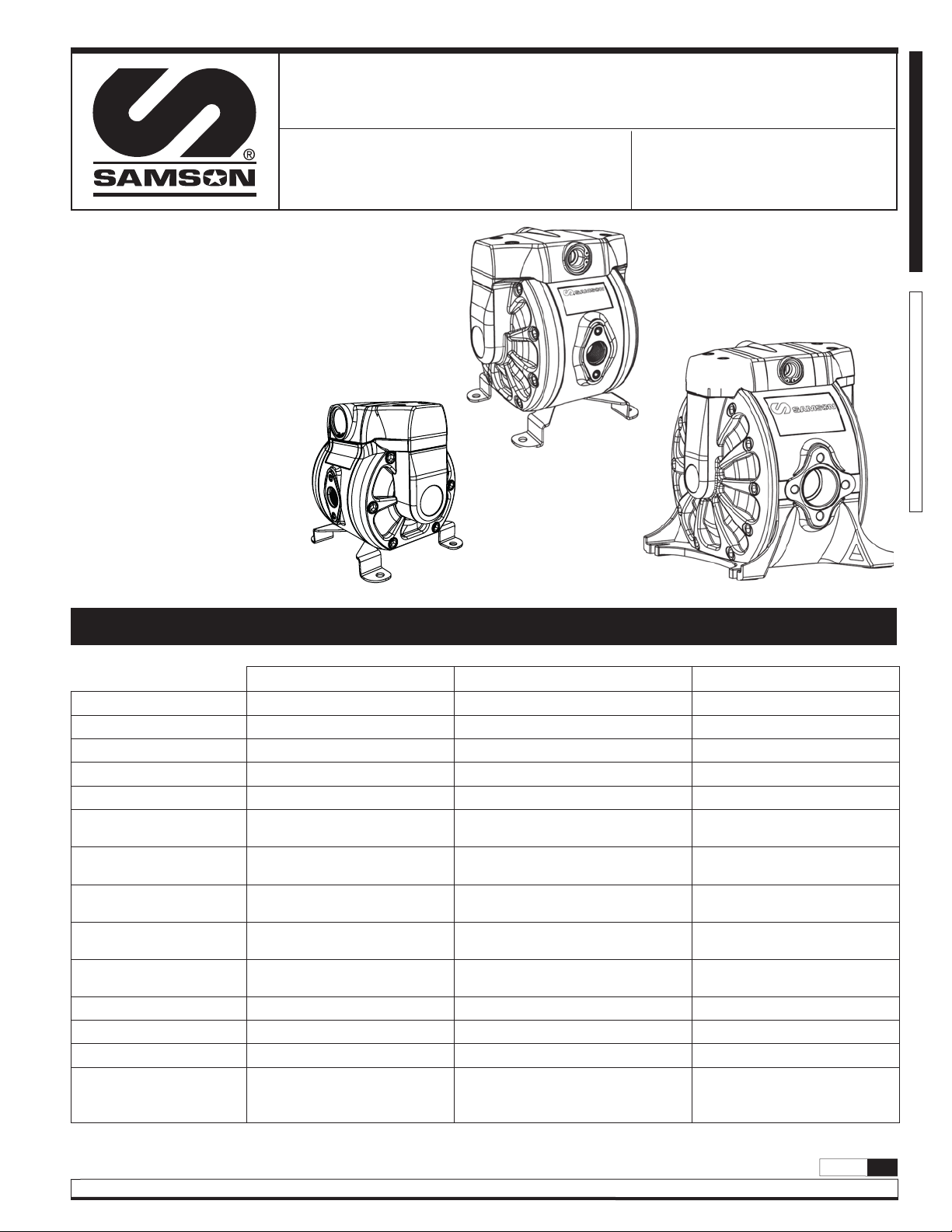
1/2" DOUBLE DIAPHRAGM PUMP DF30 (38 l/min)
1/2" DOUBLE DIAPHRAGM PUMP DF50 (50 l/min)
1" DOUBLE DIAPHRAGM PUMP DF100 (100 l/min)
Technical data 1
Warnings and cautions 2
Description 2
Capacity curves 3
Dimensions 4
Installation 5
Operating instructions 6
Composite body parts:
DF30 / DF30T 7
DF50 / DF50T composite 8
DF50 / DF50T metallic 9
DF100 10
Troubleshooting 12
Maintenance guide 13
Operation and maintenance manual
DF50
DF30
Codes:
5530XX/ 5520XX
5510XX
ENGLISHESPAÑOL
DF100
Ratio
Maximum free flow
Delivery per stroke
Air pressure operating range
Solid in suspension max size
Maximum suction head
Weight
Fluid inlet (single inlet)
Fluid inlet (double inlet)
Fluid outlet
Air inlet
Wetted part materials
Noise level
Temperature range (see
material temperature range
on page 2)
Product customization
Technical data
DF30 DF50 DF100
1:1 1:1 1:1
10 gal/min (38 l/min) 13.21 gal/min (50 l/min)
2.37 oz (0,07 l) 3.38 oz (0,1 l)
43.51 to 100 psi (3 a 7 bar) 43.5 psi - 100 psi (3 a 7 bar) 43.5 psi - 100 psi (3 a 7 bar)
0.12 in (3 mm) 0.12 in (3 mm) 0.16 in (4 mm)
13.2 ft (4 m) dry
26.25 ft (8 m) wet
4.85 lb (2, 2 kg) 7.72 lb (3,5 kg) metallic
1/2" (BSP - NPT (F) 1/2" NPSM (F) and flange with metallic body
2 x 3/8" BSP - NPT (F) 2 x 3/8" NPSM (F) with metallic body
1/2" BSP - NPT (F) 1/2" NPSM (F) and flange with metallic body
3/8" NPSM (F) 3/8" NPSM (F) 3/8" NPSM (F)
See model specifications See model specifications See model specifications
80 db 80 dB 80 dB
19.69 ft (6 m) dry
26.25 ft (8 m) wet
6.17 lb (2,8 kg) plastic
(BSP- NPT (F) and flange with plastic body)
(BSP - NPT (F) with plastic body)
(BSP - NPT (F) plastic body)
0 - 158 ºF (0 - 70 ºC) 0 - 158 ºF (0 - 70 ºC) 0 - 158 ºF (0 - 70º C)
26.42 gal/min (100 l/min)
8.45 oz (0,25 l)
14.76 ft (4,5 m) dry
22.97 ft (7 m) wet
15.87 lb (7,2 kg) metallic
14.33 lb (6,5 kg) Plastic
1" BSP/NPT (F) and flange
_
1" BSP/NPT (F) and flange
* (oz,ft,gal/min) all in EEUU units
2013_12_17-16:30
R. 12/13 855 822
Samson Corporation • One Samson Way • N.C. 28778 Swannanoa USA • Phone (828) 686-8511 • Fax (828) 686-8533
1
Page 2
Warnings and cautions
In this document you will find warnings and cautions for installation, use
and maintenance of the Direcflo pumps.
Warning
This symbol aware that there is a danger of serious bodily injury or death
if you ignore the warning described.
Warning
Carefully read the instructions and warnings before operating the equipment!
• This equipment is for professional use only
• Do not degrade the integrity of the equipment. Use only original
replacement components from Samson Corporation.
• Fluids not suitable for the pump can cause damage to the pump unit
and involve risk of serious personal injury.
• Always consult Samson Corporation if you have any questions about
the compatibility within the fluids and the pump materials, including
elastomers.
• Install and use the pump according to all local and national regulations
and abide all health and safety laws or legislation.
• The pump can produce fluid pressures equal to the air supply pressure.
Do not exceed the maximum allowable pressure of 100 psi (7 bar) air
supply. The total hydraulic pressure (differential pressure + system)
should never exceed 100 psi (7 bar).
• Never use a pump that leaks, that is damaged, that is corroded or
otherwise it may lack the capacity to contain the fluid.
• Frequently check that the bolts on the diaphragm cover of the pump are
torqued correctly.
Here’s the meaning of symbols you may find in this document and general
warnings that you should keep in mind.
Caution
This symbol aware that there is a danger of personal injury or property
damage if you ignore the caution described.
• Do not use a model with aluminium wetted surfaces to pump fluids for
human consumption, there is a possibility of trace contamination of lead.
• Danger of explosion if used 1,1,1-trichloroethane, methylene chloride
or other halogenated hydrocarbon solvents with aluminium wetted
materials. It could cause serious injury and property damage.
• Inside the pump, diaphragms separate the fluid that is being pumped
from the air supply. If a diaphragm breaks, the fluid can leak out of the
air exhaust and contaminate the environment.
• When handling hazardous fluids, always route the air exhaust into a
suitable container and locate it in a safe place.
• When the fluid source level is situated higher than the pump, (flooded
suction), the outlet tank must be at a higher level than the product to
prevent spills.
• For pumps handling hazardous fluids that are a danger to humans or to
the environment, install a suitable container surrounding the pump to
prevent any leaks or spills.
• Ensure that the operators of this equipment are trained on the operation
and limitations. Use safety equipment as safety goggles or other
equipment required.
Description
Air operated double diaphragm pumps are air-powered, reciprocating
positive displacement pumps with two pumping chambers. Two
diaphragms, centrally located in the chambers, separate the compressed
air (dry side) from the fluid being pumped (wet side). A shaft transmits
2013_12_17-16:30
the reciprocating motion of one diaphragm to the other. A directional valve
alternatively distributes the air from one chamber to the other; thus a
reciprocating movement of the diaphragms is created. With each stroke,
fluid is discharged by one of the diaphragms whilst the opposite
diaphragm sucks new fluid into the expanding chamber. Check valves, two
on the discharge side and two on the suction side, control and direct the
fluid flow.
2
855 822 R. 12/13
Samson Corporation • One Samson Way • N.C. 28778 Swannanoa USA • Phone (828) 686-8511 • Fax (828) 686-8533
Material Temperature range
PTFE 5 ºC - 105 ºC / 41 ºF - 221 ºF
NBR 10 ºC - 80 ºC / 50 ºF - 176 ºF
Acetal 10 ºC - 90 ºC / 50 ºF - 194 ºF
®
Hytrel
10 ºC - 90 ºC / 50 ºF - 194 ºF
Neopreno -18 ºC - 93 ºC / 0 ºF - 200 ºF
Santoprene
Viton
Polypropylene
®
®
®
-29 ºC - 135 ºC / -20 ºF - 275 ºF
-10 ºC - 120 ºC / -4 ºF - 248 ºF
10 ºC - 80 ºC / 50 ºF - 176 ºF
Page 3
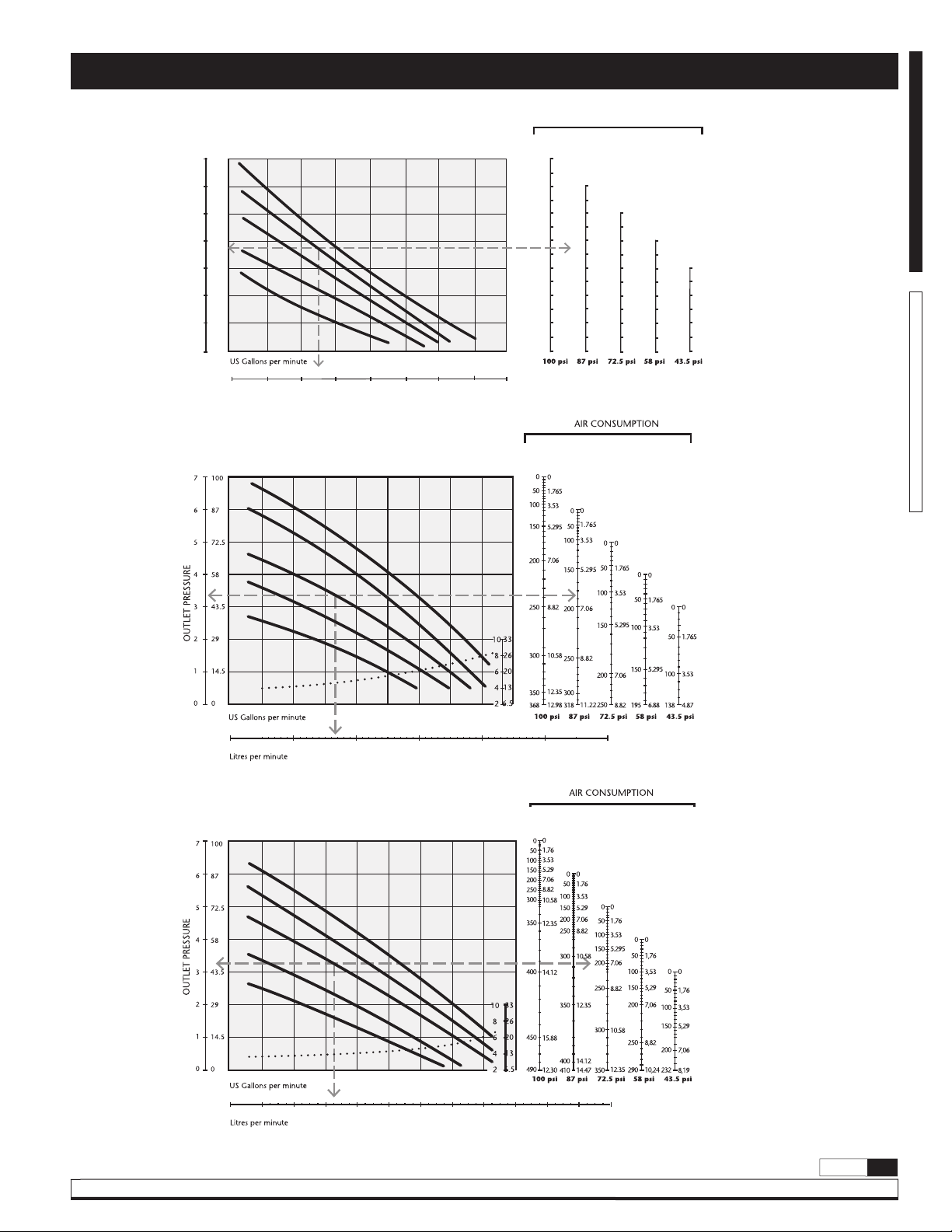
Capacity curves
DF30
DF50
HEAD
100
7
6
5
4
3
2
OUTLET PRESSURE
1
0
BAR
100 psi / 7 bar
87
87 psi / 6 bar
72.5
58
43.5
72.5 psi / 5 bar
58 psi / 4 bar
43.5 psi / 3 bar
29
14
0
PSI
0 2.6 5.8 7.4 10.5
0 5 10 15 20 25 30 35 40
Litres per minute
HEAD
100 psi / 7 bar
87 psi / 6 bar
72.5 psi / 5 bar
58 psi / 4 bar
43.5 psi / 3 bar
AIR CONSUMPTION
SCFM
Nl/min
00.0
0.00
59.3
2.01
Nl/min
2.21
2.51
2.89
3.37
3.94
4.61
5.36
6,21
7.16
8.19
9.32
10.54
11.85
SCFM
SCFM
0.00
0.00
19.8
0.67
Nl/min
50.8
78.9
104.1
126.3
145.6
162
175.5
186.1
193.7
198.4
200.3
Nl/min
SCFM
1.72
0.00
0.00
2.67
25.6
0.87
Nl/min
3.53
57.1
4.28
85.4
4.94
110.5
5.49
132.4
5.95
151.1
6.31
166.7
6.57
179.1
6.73
188.3
6.79
194.3
SCFM
1.94
0,00
0.00
2.89
20.3
0.69
Nl/min
3.74
50.8
4.49
77.6
5.12
100.8
5.65
120.3
6.07
136.3
6.38
148.6
6.59
157.3
SCFM
1.72
0,00
0.00
2.63
12.5
0.42
3.42
39
1.32
4.08
62.5
2.12
4.62
83
2.81
5.04
100.5
3.41
5.33
115
3.90
SCFM
Nl/min
SCFM
Nl/min
SCFM
Nl/min
SCFM
ENGLISHESPAÑOL
65.3
73.9
85.3
99.4
116.2
135.8
158.2
183.2
211.1
241.6
274.9
310.9
349.7
Nl/min
Feet
Meter
PSI
BAR
0 2.6 5.28 7.4 10.5 13.2 16
NPSH
0 10 20 30 40 50 60
DF100
HEAD
100 psi / 7 bar
87 psi / 6 bar
72.5 psi / 5 bar
58 psi / 4 bar
43.5 psi / 3 bar
PSI
BAR
0 2.6 5.28 7.4 10.5 13.2 16 18.5 21 23.7 26 29 31.7
0 10 20 30 40 50 60 70 80 90 100 110 120
*Tested at room temperature, using water. Flooded pump with 3.5 inches, (80 mm), positive suction head.
Samson Corporation • One Samson Way • N.C. 28778 Swannanoa USA • Phone (828) 686-8511 • Fax (828) 686-8533
Meter
NPSH
Feet
Nl/min
SCFM
Nl/min
SCFM
Nl/min
SCFM
Nl/min
SCFM
Nl/min
SCFM
R. 12/13 855 822
2013_12_17-16:30
3
Page 4
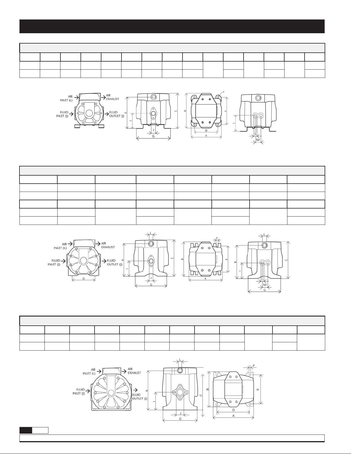
Dimensions
DF30 / DF30T
A B C D E F G H I J K L M N P
5.12" 6.3" 6.38" 4.13" 4.8" 0.31" 5.51" 5.31" 2.76"
130 mm 160 mm 162 mm 105 mm 122 mm 8 mm 140 mm 135 mm 70 mm 145 mm 24 mm 41 mm
1/2" BSP
NPT
5.71"
3/8" BSP
NPT
0.94"
M6
1,61"
Only DF30T
DF50 / DF50T
A B C D E F G H
6.14" 6.3" 6.57" 4.13" 4.8" 0.31" 5.75" 5.51"
156 mm 160 mm 167 mm 105 mm 122 mm 8 mm 146 mm 140 mm
H I J K L M N P
5.51" 2.76"
140 mm 70 mm 150 mm 24 mm 41 mm
1/2" BPS NPT
NPSM
5.91"
3/8" NPSM
0.94"
M6
1.61"
Only DF50T
DF100
A B C D E F G H I J K L
8.5" 7.44" 8.94" 6.89" 6.06" 0.35" 7.24" 8.27" 3.72"
216 mm 189 mm 227 mm 175 mm 154 mm 9 mm 184 mm 210 mm 94,51 mm 210 mm
2013_12_17-16:30
4
855 822 R. 12/13
Samson Corporation • One Samson Way • N.C. 28778 Swannanoa USA • Phone (828) 686-8511 • Fax (828) 686-8533
1"BSP
NPT
8.27"
3/8" NPSM
Page 5
Installation
Installation recommendations
• Remove the pump from its package and install it on the chosen location.
• Try to minimize the suction head. Install the pump as close as possible
to the fluid being pumped.
• Remember to have enough space around the pump to perform
maintenance tasks.
• Keep in mind to connect the inlet and outlet of the pump correctly.
• In case of diaphragm pump failure, the air exhaust will expell the
product being pumped.
• When the pump is installed in a place where a spill of fluid can cause
an environmental impact, the exhaust should be directed to a place.
where this spill could be contained.
• When installing the pump in its place, use brackets to secure its base.
• Fasten all bolts with the torques contained in this manual.
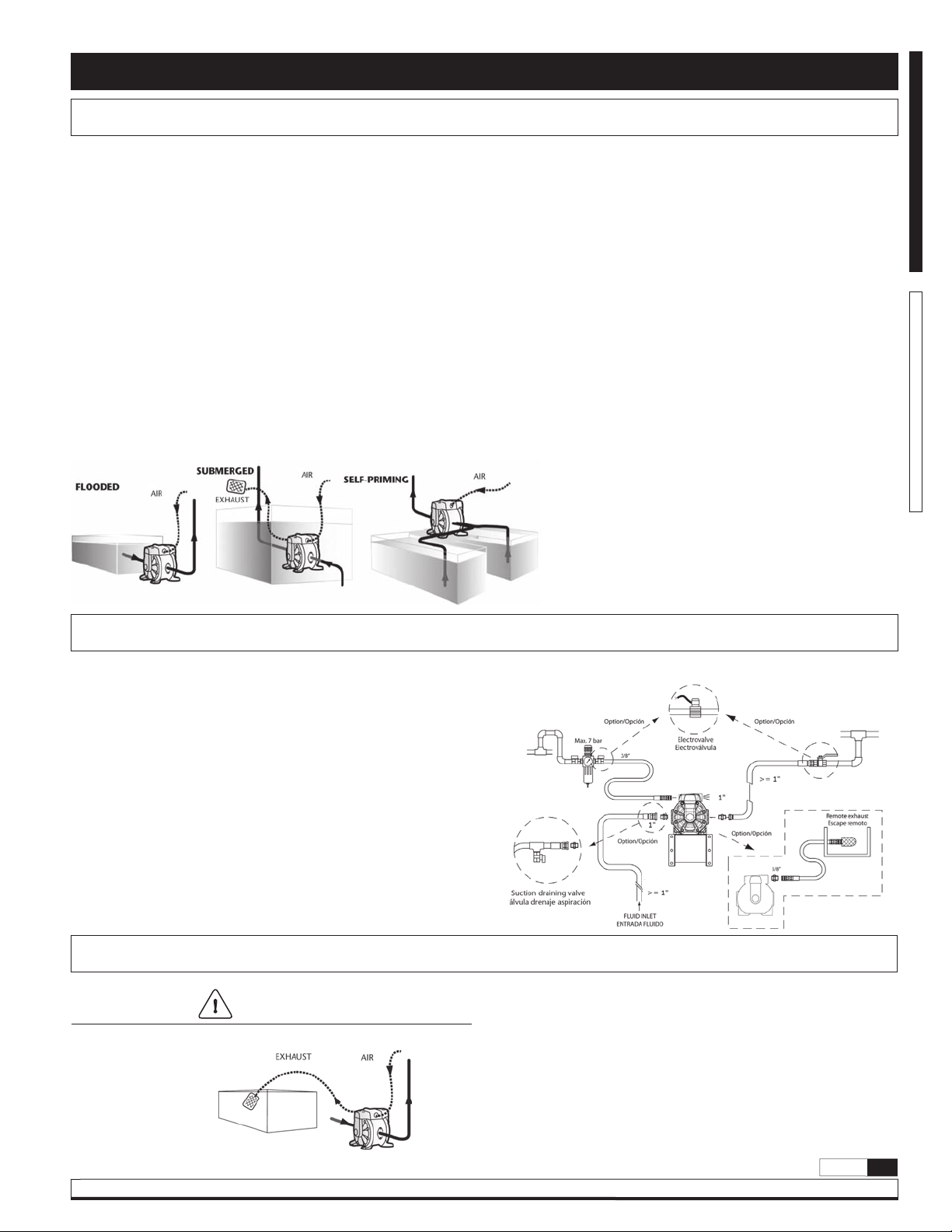
DF pumps are very easily configured and easy to install.
Flooded:
The pumping system was designed with positive pressure at the inlet. This
is the best possible installation when you need to evacuate the liquid from
the drum or tank, or when working with viscous fluids.
Not recommended for hazardous fluids.
Self-priming:
Pump is designed to generate vacuum. It is possible to evacuate all the air
from a hose or pipe without damaging the pump. Maximum suction height
is 19.69 ft (6 m), with the suction hose empty and up to 26.25 ft (8 m)
with the hose primed. (See page 1 for corresponds suction lift).
Submerged:
All pumps can be immersed in fluids. It is important to verify that all
components that are in contact with the fluid are chemically compatible.
In this case, air exhaust and fluid must be carried by hoses (optional air
connection).
NOTE: Use a pressure regulator with built-in filter inlet.
NOTE: The compressed air supply must be between 43.5 psi
(3 bar) and 100 psi (7 bar).
ENGLISHESPAÑOL
Recommended installation
The figure below shows the recommended configuration for the installation of a diaphragm pump.
Read the warnings and recommendations of the previous page before starting.
Air exhaust disposal
Warning
• Optional kit is required for remote exhaust.
The pump exhaust should be directed to a safe place, away from people,
animals and food.
• Remove the muffler.
• Connect a hose to the exhaust port of the pump and install the muffler
at the end of the hose. Use a hose with the same diameter as the
exhaust port. (If the hose is more than 5 feet (1.5 m), consult your
dealer or Samson Corporation).
• Have a moat, a protective housing, etc. at the end of the hose.
2013_12_17-16:30
R. 12/13 855 822
Samson Corporation • One Samson Way • N.C. 28778 Swannanoa USA • Phone (828) 686-8511 • Fax (828) 686-8533
5
Page 6
Installation
Warning
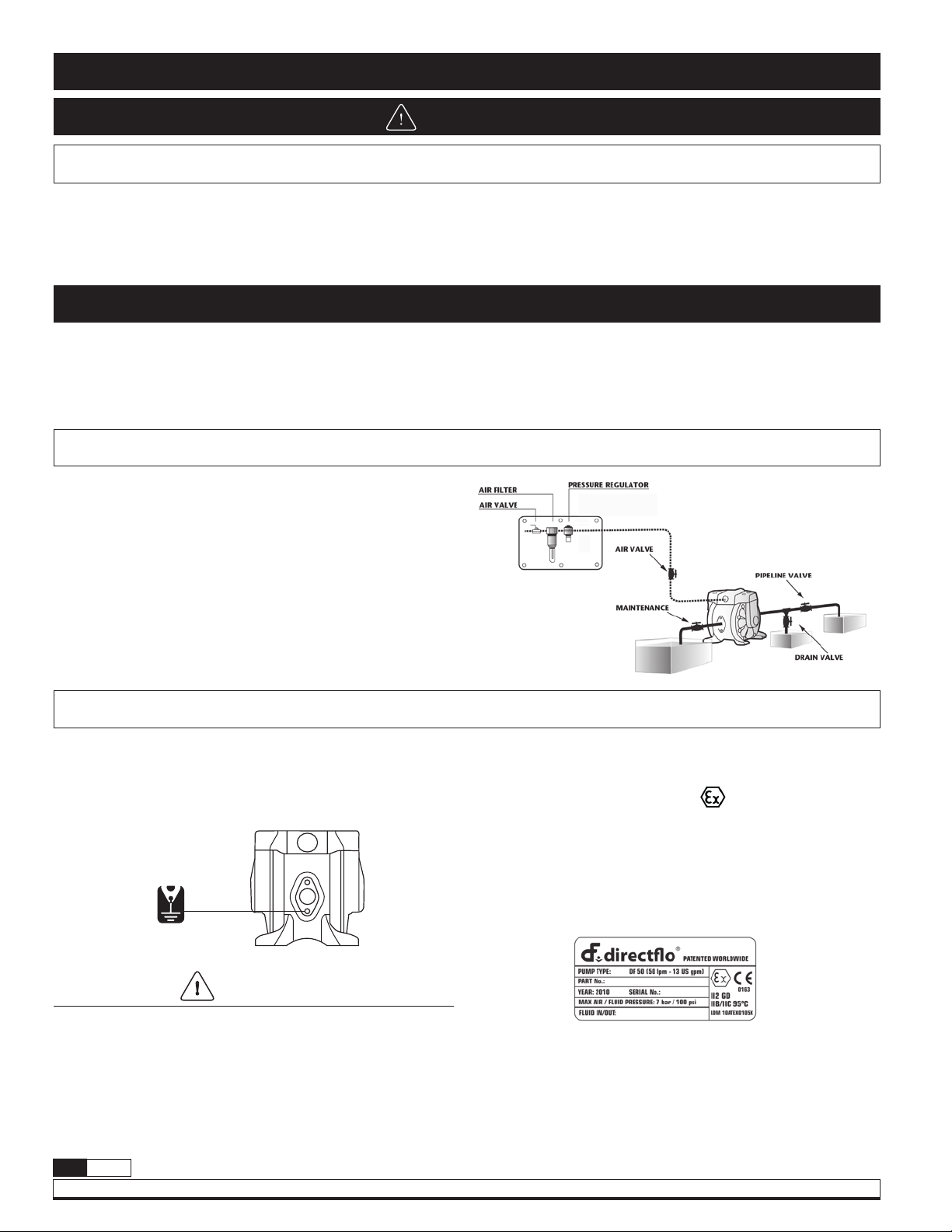
Air connection
To ensure that the air supply is sufficient to meet the demand of the pump,
the diameter of the pipe must be equal to the diameter of the supply port
of the pump. Choose auxiliary air treatment equipment and fittings with
sufficient airflow to exceed the air consumption of the pump. In addition,
Operating instructions
This pump is self-priming.
To prime it the first time, you must connect the air pump supply to a low
pressure using the pressure regulators while keeping the outlet valve open.
When fluid begins to flow from the pump outlet, the pump is primed. For
Stopping the pump
• Close the inlet valve of the pump and stop the air supply.
• Make sure for your safety that the air valve is closed.
• Turn off the air compressor, or close the valve on the air supply side of
the auxiliary equipment.
• Close the discharge valve on the discharge side, then begin to slowly
open the drain valve and discharge pressure fluid.
• Open the air valve of the pump, turn on the pump and flush the
remaining fluid.
• After ensuring that the pump was turned off and the pressure was released,
fully open and close the regulator valve and drain valve of the pump.
peripheral air treatment equipment must be installed as close as possible
to the pump unit.
The use of a coupler to connect the hoses aids future operation and
maintenance tasks.
regulation of fluid pressure, the unit must be supplied with an air pressure
between 43.5 and 100 psi (3 and 7 bar). Adjust the discharge valve on the
discharge side to control flow. For the performance characteristics of the
pump see the capacity curve shown on page 3.
Grounding the pump
• When installing the pump, be sure to perform grounding in the
specified location.
• Also connect ground wires for the auxiliary equipment and piping.
• Use a grounding cable of at least 12 gauge (2.0 mm
STICKER THAT SHOWS
THE POSITION OF THE
GROUND WIRE
2013_12_17-16:30
2
).
Warning
• Connect grounding wires to the pump, piping and all other equipment too.
• When the pump operates ungrounded or with an incorrect connection,
friction between parts and abrasion caused by some fluids that flow
inside the pump, can generate static electricity. Moreover, according to
the type of fluid pump and the installation environment (such as gases
in the air or the type of the surrounding facilities) static electricity can
cause fire or electric shock.
• If the pump you have purchased is valid for Atex, a specific Atex manual
will accompany this one. Read this manual before operating the pump.
• If the unit is marked with the symbol,
it can be used in potentially
explosive atmospheres. Below this symbol, in the nameplate of the
pump, are indicated the areas for which the equipment is approved. You
will also find the maximum allowable surface temperature in the same
plate.
6
855 822 R. 12/13
Samson Corporation • One Samson Way • N.C. 28778 Swannanoa USA • Phone (828) 686-8511 • Fax (828) 686-8533
Page 7
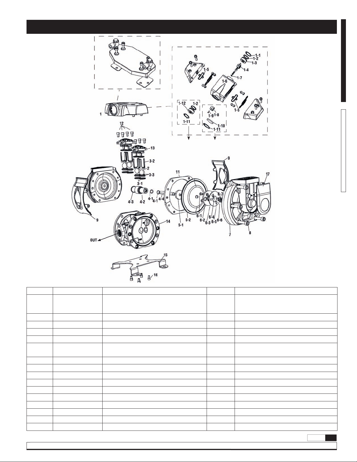
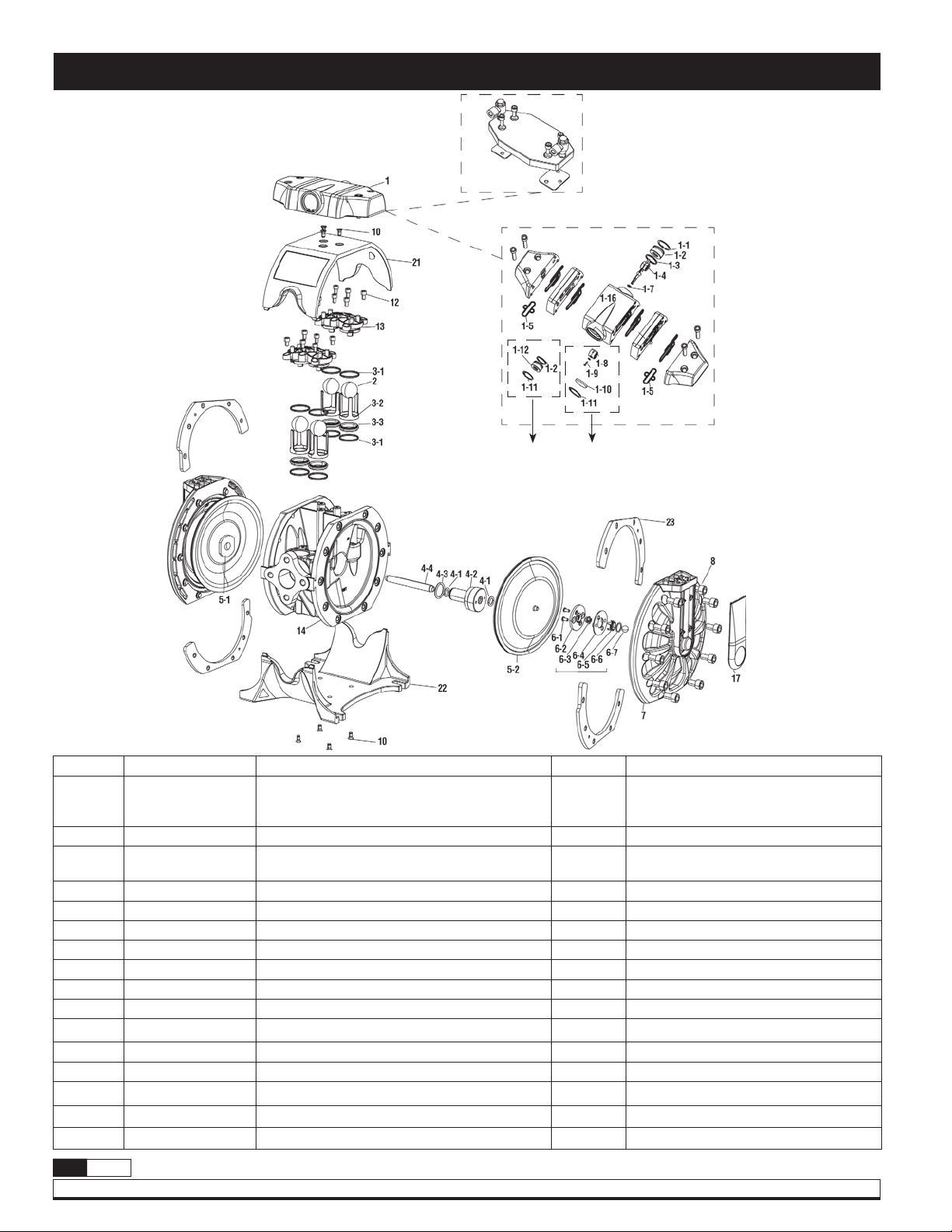
DF30 and DF30T
Composite body pump parts
ENGLISHESPAÑOL
Externally controlled
Directional valve is sold do a
kit. Assembled and verified in
Samson.
Driven
exhaust
Normal
exhaust
No. Code Description Qty. Notes
Normal exhaust
1 Table 1 Directional Valve 1 Options:
Driven exhaust
Externally controlled
2 Table 2 Balls -
3 Table3 Ball check seats / O-rings / Ball guides -
4 Table 4 Bushing / Seal / Push rod -
5 Table 5 Diaphragms -
6 Kit (558301) Air sensors - Not available in externally controlled models
7 755117 Diaphragm cover 2 (Not sold as a kit)
8 940380 Diaphragm cover bolts 12 (Not sold as a kit)
9 Table 9 Pump shields 2 (Not sold as a kit)
11 855420 Diaphragm cover washers 4 (Not sold as a kit)
12 940319 Valves cap bolts 8 (Not sold as a kit)
13 Table 13 Valves caps 2 (Not sold as a kit)
14 Table 14 Body 1 (Not sold as a kit)
15 855414 Pump support 1 (Not sold as a kit)
16 940319 Support bolts 4 (Not sold as a kit)
17 855646 Cover 2 (Not sold as a kit)
R. 12/13 855 822
Samson Corporation • One Samson Way • N.C. 28778 Swannanoa USA • Phone (828) 686-8511 • Fax (828) 686-8533
2013_12_17-16:30
7
Page 8
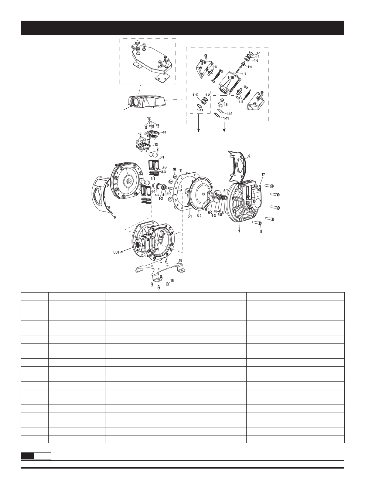
DF50 and DF50T Composite pumps
All instances
Externally
controlled
1
Composite body pump parts
Directional valve is sold do a
kit. Assembled and verified in
Samson.
Driven
exhaust
Normal
exhaust
No. Code Description Qty. Notes
Normal exhaust
1 Table 1 Directional valve 1 Options:
Driven exhaust
Externally controlled
2 Table 2 Balls -
3 Table 3 Ball check seats / O-rings / Ball guides -
4 Table 4 Bushing / Seal / Push rod -
5 Table 5 Diaphragms -
6 Kit (558301) Air sensor - Not available with externally controlled models
7 755106 Diaphragm cover 2 (Not sold as a kit)
2013_12_17-16:30
8 940380 Diaphragm cover bolts 16 (Not sold as a kit)
9 Table 9 Pump shields 2 (Not sold as a kit)
10 941126 Diaphragm cover nuts 16 (Not sold as a kit)
11 855413 Diaphragm cover washers 4 (Not sold as a kit)
12 940319 Valves cap bolts 8 (Not sold as a kit)
13 Table 13 Valves caps 2 (Not sold as a kit)
14 Table 14 Body 1 (Not sold as a kit)
15 855414 Pump support 1 (Not sold as a kit)
16 940319 Support bolts 4 (Not sold as a kit)
17 855601 Cover 2 (Not sold as a kit)
8
855 822 R. 12/13
Samson Corporation • One Samson Way • N.C. 28778 Swannanoa USA • Phone (828) 686-8511 • Fax (828) 686-8533
Page 9

DF50 y DF50T Metallic
Externally
controlled
Composite body pump parts
ENGLISHESPAÑOL
Directional valve is sold do a
kit. Assembled and verified in
Samson.
1
Driven
exhaust
Normal
exhaust
No. Code Description Qty. Notes
Normal exhaust
1 Table 1 Directional valve 1 Options:
Driven exhaust
Externally controlled
2 Table 2 Balls -
3 Table 3 Ball check seats / O-rings / Ball guides -
4 Table 4 Bushing / Seal / Push rod -
5 Table 5 Diaphragms -
6 Kit (558301) Air sensor - Not available with externally controlled models
7 755106 Diaphragm cover 2 (Not sold as a kit)
8 940380 Diaphragm cover bolts 16 (Not sold as a kit)
9 Table 9 Pump shields 2 (Not sold as a kit)
10 940506 Pump shield bolts 8 (Not sold as a kit)
12 940319 Valves cap bolts 8 (Not sold as a kit)
13 Table 13 Balls caps 2 (Not sold as a kit)
14 Table 14 Body 1 (Not sold as a kit)
17 855601 Side cover 2 (Not sold as a kit)
R. 12/13 855 822
Samson Corporation • One Samson Way • N.C. 28778 Swannanoa USA • Phone (828) 686-8511 • Fax (828) 686-8533
2013_12_17-16:30
9
Page 10
DF100
Composite body pump parts
Externally
controlled
Directional valve is sold do a
kit. Assembled and verified in
Samson.
Driven
exhaust
Normal
exhaust
No. Code Description Qty. Notes
Normal exhaust
1 Table 1 Directional valve 1 Options:
Driven exhaust
Externally controlled
2 Table 2 Balls -
3 Table 3
Ball check seats / O-rings /
Ball guides
-
4 Table 4 Bushing / Seal / Push rod -
5 Table 5 Diaphragms -
6 Kit (558301) Air sensor - Not available with externally controlled models
2013_12_17-16:30
7 755111 Diaphragm cover 2 (Not sold as a kit)
8 940334 Diaphragm cover bolts 20 (Not sold as a kit)
10 940914 Diaphragm cover nuts 7 (Not sold as a kit)
12 940319 Diaphragm cover washers 12 (Not sold as a kit)
13 Table 13 Valves caps 2 (Not sold as a kit)
14 Table 14 Body 1 (Not sold as a kit)
17 855604 Cover 2 (Not sold as a kit)
21 Table 9 Upper shield 1 (Not sold as a kit)
22 Table 9 Lower shield 1 (Not sold as a kit)
23 855416 Shield attachment 4 *Only for composite
10
855 822 R. 12/13
Samson Corporation • One Samson Way • N.C. 28778 Swannanoa USA • Phone (828) 686-8511 • Fax (828) 686-8533
Page 11

Pumps repair kit codes
Table 1 Table 2 Table 3
Pump size Samson code Directional valve Kit code Balls Kit code Ball valves seats / Seals / Cages Kit code
DF30 553010X Standard 558300.300 PTFE 558319 Stainless steel / Viton / Polypropylene 558316
552010X Standard 558300.300 ACETAL 558321 Stainless steel / Viton / Acetal 558315
552011X Standard 558300.300 ACETAL 558321 Stainless steel / Viton / Acetal 558315
DF50
DF100
Pump size Samson code Bushing / Seals / Shaft Kit code Diaphragms Kit code Air sensor Kit code
DF30 553010X PTFE / Viton / Stainless steel 558326.001 HYTREL 558337.001 Standard 558301
DF50
DF100
552015X Standard 558300.300 PTFE 558319 Stainless steel / Viton / Polypropylene 558316
552016X Standard 558300.300 ACETAL 558321 Stainless steel / Viton / Acetal 558315
552021X Standard 558300.300 ACETAL 558321 Stainless steel / Viton / Acetal 558315
552026X Standard 558300 .300 ACETAL 558321 Stainless steel / Viton / Acetal 558315
551010X Standard 558350 .300 ACETAL 558365 Stainless steel / NBR / Acetal 558357
551015X Standard 558350 .300 PTFE 558363 Stainless steel / Viton / Polypropylene 558360
DF 55x xxx
Table 4 (See note at the bottom of the page) Table 5 (See note at the bottom of the page) Table 9
552010X PTFE / NBR / Stainless steel 558304.001 HYTREL 558303.001 Standard 558301
552015X PTFE / Viton / Stainless steel 558307.001 HYTREL 558303.001 Standard 558301
552016X PTFE / Viton / Stainless steel 558307.001 HYTREL 558303.001 Standard 558301
552021X PTFE / Viton / Stainless steel 558307.001 HYTREL 558303.001 Standard 558301
552026X PTFE / Viton / Stainless steel 558307.001 HYTREL 558303.001 Standard 558301
551010X PTFE / NBR / Stainless steel 558352.001 HYTREL 558368.001 Standard 558301
551015X PTFE / Viton / Stainless steel 558353.001 HYTREL 558368.001 Standard 558301
ENGLISHESPAÑOL
DF 55x xxx
*For pumps prior to February 2013 (serial nº prior to 329041/250) the replacement kit has to be ordered without the .001 suffix
Table 9 PUMP SHIELD - (Not sold a kit one piece per code)
DF30 DF30T DF50 DF50T DF100
A = Aluminum - 755108.370
P = PP 855645
IN: ASK SAMSON
OUT: 855625 OUT: 855625 LOWER: 855636
855625.370
IN: 755109 UPPER: 755113
OUT: 755108 LOWER: 755114
IN: 855626 UPPER: 855637
Table 13 VALVE CAPS (Not sold a kit one piece per code)
DF30 DF50 DF100
A = Aluminum - 855107 855112
B = Conductive PP 855654 855654 855653
C = Acetal 855620 855620 D = Conductive Acetal 855629 855629 855635
N = Electroless Nickel Plated Aluminum - 755107.001 755112.001
P = PP 855609 855609 855633
S = SS - ASK SAMSON ASK SAMSON
Table 14 WETTED PUMP BODY (Not sold a kit one piece per code)
DF30 DF30T DF50 DF50T DF100
A = Aluminum - - 755104 755105 755110.300
B = Conductive PP 755402.300 - 755215.300 - 755315.300
C = Acetal
- -
755213.300 855619.300 -
D = Conductive Acetal 755401.300 - 755214.300 - 755314.300
N = Electroless Nickel Plated Aluminum - - ASK SAMSON - ASK SAMSON
P = PP 755400.300 - 755212.300 855608.300 755312.300
S = SS - - 755050 - 755051.300
R. 12/13 855 822
Samson Corporation • One Samson Way • N.C. 28778 Swannanoa USA • Phone (828) 686-8511 • Fax (828) 686-8533
2013_12_17-16:30
11
Page 12

Troubleshooting
The pump does not work.
Cause Recommended measure
The discharge valve on the discharge side is not open. Open the discharge valve on the discharge side.
No air supply. Turn on the compressor and open the air valve and air regulator.
The air supply pressure is low. Check the compressor and the configuration of the air line.
Air leaks in connecting elements. Check the connection elements and the tightening of the screws.
The air pipes or ancillary equipment is clogged with mud. Check and clean the air line.
The exhaust port (muffler) of the pump is clogged with mud. Check and clean the exhaust port and muffler.
The fluid pipe is clogged with mud. Check and clean the fluid line.
Pump is clogged with mud. Remove, inspect and clean the pump body.
The pump runs but no fluid comes out.
Cause Recommended measure
The valve on the suction side is not open. Open the valve on the suction side.
Too much suction or discharge height. Confirm the configuration of the pipe and reduce the height of the same.
Fluid pipe discharge side (including the filter) is clogged with mud. Check and clean the fluid line.
Pump is clogged with mud. Dismantle the pump, check and clean.
The ball and ball seat is worn or damaged. Inspect and replace parts.
The flow is decreasing.
Cause Recommended measure
The air supply pressure is low. Check the compressor and the configuration of the air line.
The air line or peripheral equipment clogged with mud. Check and clean the air line.
Valve discharge side drive will not open normally. Adjust the discharge valve discharge side.
The air mixes with the fluid. Replenish fluid and check the configuration of the pipe on the suction side.
Cavitation occurs. Adjust air supply pressure and discharge pressure and reduce the suction.
Vibrations. Adjust air supply pressure and discharge pressure. Reduce the flow of
Ice formation in the air exhaust. Remove ice from the air bypass valve and check and clean the air filter.
The fluid line (including the filter) plugged with mud. Check and clean the fluid pipe and strainer.
The exhaust port (muffler) of the pump is clogged with mud. Check and clean the exhaust port and muffler.
Pump is clogged with mud. Remove, inspect and clean the pump body.
the inlet valve to adjust pressure and volume of fluid.
Use a pipe in the exhaust air that the ice does not form in the muffler.
Leakage of fluid through the hollow exhaust (silencer).
Cause Recommended measure
The diaphragm is damaged. Remove and inspect the pump and replace the diaphragm.
Irregular noise.
Cause Recommended measure
The air supply pressure is too high. Adjust air supply pressure.
2013_12_17-16:30
The pump is clogged with sludge particles larger than the diameter allowed. Remove, check and clean the pump body.
Irregular vibration.
Cause Recommended measure
The elements of connection and the support of the pump are loose. Review each element of connection and tighten the screws.
The air supply pressure is too high. Adjust air supply pressure.
The range and ball valve vibrates. Adjust air supply pressure and exhaust pressure.
12
855 822 R. 12/13
Samson Corporation • One Samson Way • N.C. 28778 Swannanoa USA • Phone (828) 686-8511 • Fax (828) 686-8533
Page 13

In fluid with air bubbles.
Cause Recommended measure
Diaphragm damaged. Replace diaphragm.
Suction hose loose or broken. Tighten or replace.
Powered air leak pressure of 3 to 7 bar.
Cause Recommended measure
Wear directional valve. Replace directional valve components.
No start-up and is leaking air without cycles.
Cause Recommended measure
Stiff air sensors. Change air sensor.
Wear directional valve. Replace.
Troubleshooting
ENGLISHESPAÑOL
Repair and maintenance procedures
Directional valve
There are several models of directional valves mounted on diaphragm
pumps DF. Externally controlled directional valve, directional valve with
remote exhaust and normal exhaust. To identify the one you have
DF_ _ _
Kit DIRECTIONAL VALVE normal exhaust
Pos. Description Qty. Material
1 Air inlet circlip 1 Steel
2 O-ring 1 NBR
3 Inlet adaptor 1 Steel
4 Pivoting arm 1 Elastollan Delrin
5 Distributor lower seal 2 NBR
A
6 Directional valve body 1 Aluminium
7 O-ring 1 NBR - PTFE
8 Sealing drum 1 Elastollan Delrin
9 Bolt 1 Stainless steel
10 Muffler 1 Brass
11 Air outlet circlip 1 Steel
X
X
X
purchased, go to the following chart with your product code, which can
be found on the nameplate of the pump, in the case externally controlled
see the parts drawing for your pump on pages 7-10.
X
X
B
X
X
Kit DIRECTIONAL VALVE normal exhaust
Pos. Description Qty. Material
1 Air inlet circlip 1 Steel
2 O-ring 2 NBR
3 Inlet adaptor 1 Steel
4 Pivoting arm 1 Elastollan Delrin
5 Distributor lower seal 2 NBR
6 Directional valve body 1 Aluminium
7 O-ring 1 NBR - PTFE
8 Sealing drum 1 Elastollan Delrin
9 Bolt 1 Stainless steel
11 Air outlet circlip 2 Steel
12 Outlet adaptor 1 Steel
X
X
X
Maintenance (to remove the pivoting arm):
1. Remove 1, 2 ,3 , 10, 11, 12
2. Remove 9
3. Remove 4, 7, 8
R. 12/13 855 822
Samson Corporation • One Samson Way • N.C. 28778 Swannanoa USA • Phone (828) 686-8511 • Fax (828) 686-8533
2013_12_17-16:30
13
Page 14

Repair and maintenance procedures
Torques necessary for the proper functioning of the pump
For proper operation of the pump and to prevent accidents which may damage equipment and in the worst case, people, you must periodically review
the torques of the diaphragms covers and the DIRECTIONAL VALVE. In the next table are shown the appropriate torques for this purpose:
Diaphragm cover 70.81 lbf·in (8 N·m)
Torques DF30
Directional valve 44.25 lbf·in (5 N·m)
Valve cap 30.9 lbf·in (2 N·m) composite
Diaphragm cover 48.67 - 53.1 lbf·in (5,5 - 6 N·m)
Torques DF50
Directional valve 44.25 lbf·in (5N·m)
Valve cap 35.4 lbf·in (4 N·m) Aluminium - 30.9 lbf·in (2 N·m) composite
Diaphragm cover 137.7 lbf·in (15 N·m)
Torques DF100
Directional valve 44.25 lbf·in (5 N·m)
Valve cap 35.4 lbf·in (4 N·m) Aluminium - 30.9 lbf·in (2 N·m) composite
Diaphragm replacement
Before any intervention: DISCONNECT AIR SUPPLY OF THE PUMP.
IT IS NOT NECESSARY TO REMOVE THE PUMP FROM THE FLUID LINE.
1. Close fluid valves.
2. Drain the fluid inside the pump. Anticipate a drainage of fluid from inside
the pump.
3. Remove the directional valve while being careful not to damage the
seals shown in the first figure.
4. Remove the diaphragm cap.
NOTE: To tighten these screws you must use a torque wrench
calibrated to (see torque table in this page).
5. Remove the cover by gently pulling back.
6. Remove the used diaphragm and place the new one in the proper
position.
Assemble components.
Remove the side cover on the right of the fluid inlet as shown in the figure,
following the procedure to “Replace diaphragms".
Once the shaft is visible, use the following procedures:
1. Remove the shaft from its housing by pulling it from one end.
2013_12_17-16:30
The Teflon® sleeve is threaded into the body. To remove use snap ring
pliers in the two holes indicated in the figure.
3
A
4
6
5
Pushing rod
2. Once the cap has been removed, remove the quad ring inside the
pump body.
3. Replace the kit following the correct order shown in the assembly
drawing.
Reassemble the pump in reverse order.
14
855 822 R. 12/13
Samson Corporation • One Samson Way • N.C. 28778 Swannanoa USA • Phone (828) 686-8511 • Fax (828) 686-8533
Page 15

Repair and maintenance procedures
Ball valves replacement
1. Close fluid valves.
2. Drain the fluid from inside the pump. Anticipate a drainage of fluid
from inside the pump.
3. Loosen the screws to remove the directional valve. Take special care with
the seals.
4. Remove the valve cover by loosening the screws with an Allen
wrench. Take note of the orientation of the cap, as it is critical to
replace it correctly during reassembly.
Attention
To avoid fluid restriction and leakages, follow the position of the vall
checks guides in teh figure above. the valves cups must be placed with the
area indicated in the figure below facing the body.
5. Install a new set of valves according to these assembly drawings.
Ensure that the ball guides are assembled as shown in the figure on
the left, and tighten the screws with a maximum torque (see torque
table page 14).
6. Assemble the directional valve with being careful not to damage
the O-rings and tighten the screws with a maximum torque of
44.25 lbf·in (5 N·m).
ENGLISHESPAÑOL
Air sensor (only for models with )
The air sensors are on the inside part of the diaphragm covers. To access
them, follow the procedure for “Replacing diaphragms".
Samson Corporation • One Samson Way • N.C. 28778 Swannanoa USA • Phone (828) 686-8511 • Fax (828) 686-8533
Once removed the covers following procedure:
1. Remove the two screws that secure the air sensor to the top.
2. Remove all components of the sensor. Clean the area.
3. Introduce new components in the order shown.
4. Fit the cover on the pump and tighten the screws to the body of the
pump. Maximum tightening torque (see torque table page 14).
Fit the remaining components in reverse order.
R. 12/13 855 822
2013_12_17-16:30
15
Page 16

www.samsoncorporation.com
2013_12_17-16:30
Distributed by
16
855 822 R. 12/13
Samson Corporation • One Samson Way • N.C. 28778 Swannanoa USA • Phone (828) 686-8511 • Fax (828) 686-8533
Page 17

1/2" BOMBA DE MEMBRANA SERIES DF30 (38 l/min)
1/2" BOMBA DE MEMBRANA SERIES DF50 (50 l/min)
1" BOMBA DE MEMBRANA SERIES DF100 (100 l/min)
Datos técnicos 17
Advertencias y preacuciones 18
Descripción 18
Curvas de capacidad 19
Dimensiones 20
Instalación 21
Modos de operación 22
Despices y repuestos de la bomba:
DF30 / DF30T 23
DF50 / DF50T composite 24
DF50 / DF50T metálica 25
DF100 26
Anomalías y soluciones 28
Reparación y mantenimiento 29
Guía de servicio técnico y mantenimiento
DF50
DF30
Código:
5530XX
5520XX
5510XX
DF100
ENGLISHESPAÑOL
Datos técnicos
DF30 DF50 DF100
Ratio
Máximo caudal salida libre
Desplazamiento por
embolada
Rango de presión
Max. tamaño de partículas en
suspensión
Altura máxima de succión
Peso
Entrada de fluido (cuerpo
con entrada simple)
Entrada de fluido (cuerpo
con entrada doble)
Salida de fluido
Entrada de aire
Partes húmedas
Nivel de fluido
Rango de temperaturas de
trabajo (consultar
característica de los
materiales en página 18).
Samson Corporation • One Samson Way • N.C. 28778 Swannanoa USA • Phone (828) 686-8511 • Fax (828) 686-8533
1:1 1:1 1:1
38 l/min (10 gal/min) 50 l/min (13.21 gal/min) 100 l/min (26.42 gal/min)
0,07 l (2.37 oz) 0,1 l (3.38 oz) 0,25 l (8.45 oz)
3 a 7 bar (43.51 to 100 psi) 3 a 7 bar (43.5 psi - 100 psi) 3 a 7 bar (43.5 psi - 100 psi)
3 mm (0.12 in) 3 mm (0.12 in) 4 mm (0.16 in)
4 m (13.2 ft) seco
8 m (26.25 ft) húmedo
2, 2 kg (4,85 lb)
1/2" BSP - NPT (H)
2 x 3/8" BSP - NPT (H)
1/2" BSP - NPT (H)
3/8" NPSM (H) 3/8" NPSM (H) 3/8" NPSM (H)
Ver especificaciones de los modelos Ver especificaciones de los modelos Ver especificaciones de los modelos
80 db 80 dB 80 dB
6 m (19.69 ft) seco
8 m (26.25 ft) húmedo
3,5 kg (7.72 lb) metálica
2,8 kg (6.17 lb) plástica
1/2" NPSM (H) y bridas cuerpo metálico
(BSP- NPT (H) para cuerpo plástico)
2 x 3/8" NPSM (H) y bridas cuerpo metálico
(BSP - NPT (H) para cuerpo plástico)
1/2" NPSM (H) (BSP - NPT (H) para cuerpo
plástico)
4,5 m (14.76 ft) seco
7 m (22.97 ft) húmedo
7,2 kg (15.87 lb) metálica
6,5 kg (14.33 lb) plástica
1" BSP - NPT (H) y brida
_
1" BSP/NPT (H) y brida
0 - 70 ºC (0 - 158 ºF) 0 - 70 ºC (0 - 158 ºF) 0 - 70 ºC (0 - 158 ºF)
R. 12/13 855 822
2013_12_17-16:30
17
Page 18

Advertencias y preacuciones
En este documento usted encontrará advertencias y precauciones
para la instalación, uso y mantenimiento de las bombas Direcflo.
Advertencia
Este símbolo alerta de que si no se siguen las instrucciones indicadas se
puede producir una situación de lesión grave o muerte.
Advertencia
¡Lea atentamente el manual de instrucciones y sus advertencias antes de empezar a operar con el equipo!
• Este equipo es únicamente para uso profesional.
• No altere la integridad del equipo. Use solamente componentes
originales de Samson Corporation.
• Los fluidos no adecuados para la bomba pueden causar daños a la
unidad de la bomba e implicar riesgo de graves daños personales.
Consulte siempre al distribuidor de Samson Corporation si se tiene
alguna duda sobre la compatibilidad de los fluidos con los materiales
de la bomba, incluyendo los elastómeros.
• Instale y use siempre la bomba según la normativa y la legislación
sanitaria y de seguridad, tanto local como nacional.
• La bomba puede producir presiones de fluido iguales a la presión de
alimentación del aire. No exceder la presión máxima permitida de
alimentación de aire de 7 bar (100 psi). La presión hidráulica total
(presión del sistema + presión diferencial) no deberá exceder nunca
7 bar (100 psi).
• No utilice nunca una bomba que tenga fugas o daños, esté corroída o
de otra forma carezca de la capacidad para contener el fluido
interno o la presión del aire.
• Comprobar con frecuencia que los tornillos de las tapas de la bomba
están correctamente ajustados.
• No use modelos cuya parte húmeda esté basada en aluminio para
A continuación le indicamos el significado de los símbolos y mencionamos
unas advertencias generales que usted debe tener en cuenta.
Atención
Este símbolo alerta de daños o destrucción del equipamiento si no se
siguen las instrucciones.
productos de consumo humano, es posible que existan trazas de plomo.
• Peligro de explosión si se usa 1,1,1-tricloroetano, cloruro de metileno
u otros disolventes de hidrocarburos halogenados en sistemas de
fluido a presión que tengan componentes de aluminio humedecido.
Podría causar graves daños materiales y personales incluso mortales.
• En el interior de la bomba, dos membranas separan el fluido bombeado
de la alimentación de aire. Si se rompe una membrana, el fluido puede
salir proyectado por el orificio de evacuación de aire.
• Cuando se manejen fluidos peligrosos, conecte siempre el orificio de
evacuación de aire a un recipiente adecuado y situado en un lugar
seguro. (Sistema de conexión opcional a petición del cliente. No se
suministra con el equipo).
• Cuando la fuente de producto se encuentre a un nivel más elevado que
la bomba (aspiración inundada), la impulsión deberá ser dirigida por un
tubo a un nivel más alto que el producto para impedir los derrames
causados por derivación sifónica.
• En las bombas que manejen fluidos peligrosos para las personas o el
medio ambiente, se debe instalar algún tipo de recipiente o contenedor
para recoger posibles fugas y evitar su derrame.
• Asegúrese de que el operario de este equipo esté formado en cuanto a
la operación, limitaciones y uso de equipamiento de seguridad como
gafas de seguridad u otro equipamiento requerido.
Descripción
La bomba de membrana neumática es una bomba aspirante e impelente
de desplazamiento positivo, accionada por aire y con dos cámaras de
bombeo. Dos membranas ubicadas centralmente en las cámaras, separan
el aire comprimido (lado seco) del fluido bombeado (lado húmedo). Las
2013_12_17-16:30
membranas están conectadas entre sí mediante un eje flotante cuyo
funcionamiento permite la minimización del flujo pulsante. Una válvula
(motor neumático) distribuye el aire de una cámara a la otra
alternativamente, produciendo así un movimiento recíproco de las
membranas.
En cada embolada, una de las membranas desplaza el fluido, mientras que
la membrana opuesta aspira nuevo fluido al interior de la cámara de
expansión. Cuatro válvulas de bola, dos en el lado de aspiración y dos en
el lado de impulsión, controlan y dirigen el flujo del fluido.
18
855 822 R. 12/13
Samson Corporation • One Samson Way • N.C. 28778 Swannanoa USA • Phone (828) 686-8511 • Fax (828) 686-8533
Materiales Temperatura de trabajo
PTFE 5 ºC - 105 ºC / 41 ºF - 221 ºF
NBR 10 ºC - 80 ºC / 50 ºF - 176 ºF
Acetal 10 ºC - 90 ºC / 50 ºF - 194 ºF
®
Hytrel
10 ºC - 90 ºC / 50 ºF - 194 ºF
Neopreno -18 ºC - 93 ºC / 0 ºF - 200 ºF
Santoprene
Viton
TM
®
-29 ºC - 135 ºC / -20 ºF - 275 ºF
-10 ºC - 120 ºC / -4 ºF - 248 ºF
Polipropileno 10 ºC - 80 ºC / 50 ºF - 176 ºF
Page 19

Curvas de capaciad
DF30
DF50
HEAD
100
7
6
5
4
3
2
OUTLET PRESSURE
1
0
BAR
100 psi / 7 bar
87
87 psi / 6 bar
72.5
58
43.5
72.5 psi / 5 bar
58 psi / 4 bar
43.5 psi / 3 bar
29
14
0
PSI
0 2.6 5.8 7.4 10.5
0 5 10 15 20 25 30 35 40
Litres per minute
HEAD
100 psi / 7 bar
87 psi / 6 bar
72.5 psi / 5 bar
58 psi / 4 bar
43.5 psi / 3 bar
AIR CONSUMPTION
SCFM
Nl/min
00.0
0.00
59.3
2.01
Nl/min
2.21
2.51
2.89
3.37
3.94
4.61
5.36
6,21
7.16
8.19
9.32
10.54
11.85
SCFM
SCFM
0.00
0.00
19.8
0.67
Nl/min
50.8
78.9
104.1
126.3
145.6
162
175.5
186.1
193.7
198.4
200.3
Nl/min
SCFM
1.72
0.00
0.00
2.67
25.6
0.87
Nl/min
3.53
57.1
4.28
85.4
4.94
110.5
5.49
132.4
5.95
151.1
6.31
166.7
6.57
179.1
6.73
188.3
6.79
194.3
SCFM
1.94
0,00
0.00
2.89
20.3
0.69
Nl/min
3.74
50.8
4.49
77.6
5.12
100.8
5.65
120.3
6.07
136.3
6.38
148.6
6.59
157.3
SCFM
1.72
0,00
0.00
2.63
12.5
0.42
3.42
39
1.32
4.08
62.5
2.12
4.62
83
2.81
5.04
100.5
3.41
5.33
115
3.90
SCFM
Nl/min
SCFM
Nl/min
SCFM
Nl/min
SCFM
ENGLISHESPAÑOL
65.3
73.9
85.3
99.4
116.2
135.8
158.2
183.2
211.1
241.6
274.9
310.9
349.7
Nl/min
Feet
Meter
PSI
BAR
0 2.6 5.28 7.4 10.5 13.2 16
NPSH
0 10 20 30 40 50 60
DF100
HEAD
100 psi / 7 bar
87 psi / 6 bar
72.5 psi / 5 bar
58 psi / 4 bar
43.5 psi / 3 bar
PSI
BAR
0 2.6 5.28 7.4 10.5 13.2 16 18.5 21 23.7 26 29 31.7
0 10 20 30 40 50 60 70 80 90 100 110 120
*Ensayo realizado con agua a temperatura ambiente y bomba inundada en 80 mm de succión positiva.
Samson Corporation • One Samson Way • N.C. 28778 Swannanoa USA • Phone (828) 686-8511 • Fax (828) 686-8533
Meter
NPSH
Feet
Nl/min
SCFM
Nl/min
SCFM
Nl/min
SCFM
Nl/min
SCFM
Nl/min
SCFM
R. 12/13 855 822
2013_12_17-16:30
19
Page 20

Dimensiones
DF30 / DF30T
A B C D E F G H I J K L M N P
130 mm 160 mm 162 mm 105 mm 122 mm 8 mm 140 mm 135 mm 70 mm
5.12" 6.3" 6.38" 4.13" 4.8" 0.31" 5.51" 5.31" 2.76" 5.71" 0.94" 1.61"
1/2" BSP
NPT
145 mm
3/8" BSP
NPT
24 mm
M6
41 mm
Solo DF30T
DF50 / DF50T
A B C D E F G H
156 mm 160 mm 167 mm 105 mm 122 mm 8 mm 146 mm 140 mm
6.14" 6.3" 6.57" 4.13" 4.8" 0.31" 5.75" 5.51"
H I J K L M N P
140 mm 70 mm
5.51" 2.76" 5.91" 0.94" 1.61"
1/2" BPS NPT
NPSM
150 mm
3/8" NPSM
24 mm
M6
41 mm
Solo DF50T
DF100
A B C D E F G H I J K L
216 mm 189 mm 227 mm 175 mm 154 mm 9 mm 184 mm 210 mm 94,51 mm
8.5" 7.44" 8.94" 6.89" 6.06" 0.35" 7.24" 8.27" 3.72" 8.27"
2013_12_17-16:30
20
855 822 R. 12/13
Samson Corporation • One Samson Way • N.C. 28778 Swannanoa USA • Phone (828) 686-8511 • Fax (828) 686-8533
1"BSP
NPT
210 mm
3/8" NPSM
Page 21

Instalación
Recomendaciones para la instalación
• Retire la bomba de la caja e instálela en el lugar elegido.
• Trate de reducir al mínimo la altura de aspiración.
• Recuerde disponer de espacio suficiente alrededor de la bomba para
realizar las tareas de mantenimiento.
• Tenga siempre en cuenta usar correctamente la entrada y la salida de la
bomba.
• En caso de fallo del diafragma el escape de aire de la bomba puede
contener lodo.
• Cuando la bomba se instala en un lugar en el que pueda tener lugar un
impacto en el medio ambiente, el escape debe orientarse hacia un lugar
donde no haya impacto ambiental.
• Cuando instale la bomba en su lugar, utilice los soportes en la base y
asegure la bomba fijándola con los tornillos de amarre.
• Apriete todos los tornillos de las tapas de la bomba.
IN UNDAD A SUMERGI DA ASPIRA CIÓN
Las bombas DF son muy flexibles y fáciles de instalar.
Inundada:
El sistema de bombeo se diseñó para presión positiva en la aspiración.
Esta es la mejor forma de instalación cuando se necesite evacuar todo el
líquido del bidón o depósito, o cuando se trabaje con fluidos viscosos. No
recomendada para fluidos peligrosos.
Aspiración:
La bomba DF está diseñada para generar vacío en la aspiración. Es posible
evacuar todo el aire de una manguera o tubería sin dañar la bomba. La
altura máxima de succión es de 6 m con la manguera de succión vacía y
hasta 8 m con la manguera cebada (ver página 17).
Sumergido:
Todas las bombas DF se pueden sumergir en los fluidos. Es importante
que verifique que todos los componentes que están en contacto con el
fluido son químicamente compatibles. En este caso, las salidas de aire y
fluido deben ser conducidas al exterior mediante mangueras. (Sistema de
conexión de aire opcional).
NOTA: Utilice un regulador de presión con filtro
incorporado en la entrada de aire.
NOTA: La presión de alimentación de aire debe estar
comprendida entre 3 bar (43,5 psi) y 7 bar (100 psi).
ENGLISHESPAÑOL
Instalación recomendada
La siguiente figura muestra la configuración recomendada para
la instalación de una bomba de diafragma.
Lea atentamente las advertencias y recomendaciones de la
página anterior para realizar dicha instalación.
Disposición del escape exterior
Advertencia
El escape de la bomba debe estar orientado hacia un lugar seguro,
alejado de la circulación humana, de animales y de alimentos.
Samson Corporation • One Samson Way • N.C. 28778 Swannanoa USA • Phone (828) 686-8511 • Fax (828) 686-8533
• Es necesario el kit opcional de salida conductiva.
• Retire el silenciador.
• Conecte una manguera con conexión a tierra al orificio de escape de la
bomba e instale el silenciador en la punta de la manguera. Utilice una
manguera del mismo diámetro que el orificio de escape. (Si la
manguera mide más de 5 metros consulte al distribuidor o nuestra
oficina regional).
• Disponga un foso, una caja de protección, etc. en el extremo de la
manguera.
R. 12/13 855 822
2013_12_17-16:30
21
Page 22

Instalación
Advertencia
Conexión toma de aire
Para que el suministro de aire sea suficiente para satisfacer la demanda de
la bomba, el diámetro de la tubería debe ser igual al diámetro del orificio de
suministro de la bomba. También elija equipos auxiliares y materiales con
suficiente flujo de aire para el consumo de aire de la bomba.
Modo de operación
Esta bomba es auto-cebante. Para cebarla la primera vez, es conveniente
conectar el aire a la bomba a la presión deseada con el regulador de presión,
manteniendo la válvula de salida abierta.
Cuando el fluido empieza a salir, la bomba está cebada. Para su regulación
Parada de la bomba
• Cierre la válvula de entrada de fluido de la bomba y corte el suministro de aire.
• Compruebe por su seguridad que la válvula de aire de la bomba esté cerrada.
• Apague el compresor de aire o cierre la válvula en el lado de suministro
de aire de los equipos auxiliares.
• Cierre la válvula de impulsión en el lado de descarga, comience a abrir
lentamente la válvula de drenaje y descargue el fluido bajo presión.
• Abra la válvula de aire de la bomba, ponga en funcionamiento la bomba
y descargue el fluido remanente.
• Después de asegurarse de que la bomba se apagó y la presión se liberó,
abra completamente el regulador y cierre la válvula de aire y la válvula
de drenaje de la bomba.
También considere el uso y la estabilidad de la presión de aire. Además,
el equipo periférico debe estar instalado lo más cerca posible de la unidad
de la bomba.
El uso de un acoplador para conectar cada manguera facilita la operación
y las tareas de mantenimiento.
mediante presión de fluido se debe alimentar con presión de aire comprendida
entre 3 y 7 bar (43.5 - 100 psi). Ajuste la válvula de impulsión en el lado de
descarga. Para la relación entre el flujo, la presión de suministro de aire y la
presión de descarga, vea la curva de capacidad en la página 19.
Opción Conexión a tierra
• Cuando instale la bomba, asegúrese de realizar la conexión a tierra en
el lugar especificado.
• Conecte también conductores a tierra para los equipos auxiliares y las tuberías.
• Utilice un cable con conexión a tierra de por lo menos 2,0 mm
ESTA ETIQUETA
MUESTRA LA POSICIÓN
DEL CABLE A TIERRA
2013_12_17-16:30
2
(12 gauge).
• Si la bomba que ha adquirido es válida para Atex, a este manual lo
acompañará uno específico para Atex. Lea este manual antes de operar
con la bomba.
• Si la bomba viene marcada con el símbolo
en atmósferas potencialmente explosivas. Debajo de este símbolo, en
las placa de identificación de la bomba, vienen indicadas las zonas para
las que el equipo está aprobado. Encontrará también la temperatura de
superficie máxima permitida en la placa de su bomba.
Advertencia
• Asegúrese de conectar conductores a tierra para la bomba, tuberías y otros
equipos conectados.
• Cuando la bomba opera sin conexión a tierra o con una conexión incorrecta,
la fricción entre las piezas y la abrasión causada por algunos fluidos que
fluyen dentro de la bomba pueden generar electricidad estática. Además,
según el tipo de fluido a bombear y el ambiente de la instalación (como
gases en el aire o el tipo de las instalaciones circundantes) la electricidad
estática puede ser causa de incendio o choque eléctrico.
22
855 822 R. 12/13
Samson Corporation • One Samson Way • N.C. 28778 Swannanoa USA • Phone (828) 686-8511 • Fax (828) 686-8533
, esta puede ser usada
Page 23

DF30 and DF30T
Pilotaje externo
Despiece y repuestos de la bomba
Escape
conducido
Escape
normal
ENGLISHESPAÑOL
El distribuidor de aire se vende
como kit.
Ensamblado y verificado en
Samson.
SALIDA
Nº Referencia Descripción Cant. Nota
Escape normal
1 Tabla 1 Motor de aire 1 Opciones:
Escape conducido
Pilotaje externo
2 Tabla 2 Bolas -
3 Tabla 3 Asiento / Junta / Jaula -
4 Tabla 4 Casquillo / Junta / Eje -
5 Tabla 5 Diafragmas -
6 Kit (558301) Sensor de aire - No disponible con pilotaje externo
7 755117 Tapas de diafragma 2 (No se vende como kit)
8 940380 Tornillo tapas diafragma 12 (No se vende como kit)
9 Tabla 9 Carenas 2 (No se vende como kit)
11 855420 Tornillos 4 (No se vende como kit)
12 940319 Tornillos tapas válvula 8 (No se vende como kit)
13 Tabla 13 Tapas válvula 2 (No se vende como kit)
14 Tabla 14 Cuerpo 1 (No se vende como kit)
15 855414 Embellecedor 1 (No se vende como kit)
16 940319 Tornillos de soporte 4 (No se vende como kit)
17 855646 Cover 2 (No se vende como kit)
R. 12/13 855 822
Samson Corporation • One Samson Way • N.C. 28778 Swannanoa USA • Phone (828) 686-8511 • Fax (828) 686-8533
2013_12_17-16:30
23
Page 24

DF50 and DF50T Composite
Despiece y repuestos de la bomba
Pilotaje externo
El distribuidor de aire se vende
como kit.
Ensamblado y verificado en
Samson.
Escape
conducido
Escape
normal
SALIDA
Nº Referencia Descripción Cant. Nota
Escape normal
1 Tabla 1 Motor de aire 1 Opciones:
Escape conducido
Pilotaje externo
2 Tabla 2 Bolas -
3 Tabla 3 Asiento / Junta / Jaula -
4 Tabla 4 Casquillo / Junta / Eje -
5 Tabla 5 Diafragmas -
6 558301 Sensor de aire - No disponible con pilotaje externo
7 755106 Tapas de diafragma 2 (No se vende como kit)
2013_12_17-16:30
8 940380 Tornillo tapas de diafragma 16 (No se vende como kit)
9 Tabla 9 Carenas 2 (No se vende como kit)
10 941126 Tuercas cámaras 16 (No se vende como kit)
11 855413 Arandela cámaras 4 (No se vende como kit)
12 940319 Tornillos tapas válvula 8 (No se vende como kit)
13 Tabla 13 Tapas válvula 2 (No se vende como kit)
14 Tabla 14 Cuerpo 1 (No se vende como kit)
15 855414 Soporte de la bomba 1 (No se vende como kit)
16 940319 Tornillos de soporte 4 (No se vende como kit)
17 855601 Embellecedor 2 (No se vende como kit)
24
855 822 R. 12/13
Samson Corporation • One Samson Way • N.C. 28778 Swannanoa USA • Phone (828) 686-8511 • Fax (828) 686-8533
Page 25

DF50 y DF50T Metálica
Despiece y repuestos de la bomba
ENGLISHESPAÑOL
Pilotaje externo
El distribuidor de aire se vende
como kit.
Ensamblado y verificado en
Samson.
SALIDA
Escape
conducido
Escape
normal
Nº Referencia Descripción Cant. Nota
Escape normal
1 Tabla 1 Motor de aire 1 Opciones:
Escape conducido
Pilotaje externo
2 Tabla 2 Bolas -
3 Tabla 3 Asiento / Junta / Jaula -
4 Tabla 4 Casquillo / Junta / Eje -
5 Tabla 5 Diafragmas -
6 558301 Sensor de aire - No disponible con pilotaje externo
7 755106 Tapas de diafragma 2 (No se vende como kit)
8 940380 Tornillo tapas diafragma 16 (No se vende como kit)
9 Tabla 9 Carenas 2 (No se vende como kit)
10 940506 Tornillos 8 (No se vende como kit)
12 940319 Tornillos tapas válvula 8 (No se vende como kit)
13 Tabla 13 Tapas válvula 2 (No se vende como kit)
14 Tabla 14 Cuerpo 1 (No se vende como kit)
17 855601 Embellecedor 2 (No se vende como kit)
R. 12/13 855 822
Samson Corporation • One Samson Way • N.C. 28778 Swannanoa USA • Phone (828) 686-8511 • Fax (828) 686-8533
2013_12_17-16:30
25
Page 26

DF100
Despiece y repuestos de la bomba
Pilotaje externo
El distribuidor de aire se vende
como kit.
Ensamblado y verificado en
Samson.
Escape
conducido
Escape
normal
Nº Referencia Descripción Cant. Nota
Escape normal
1 Tabla 1 Motor de aire 1 Opciones:
Escape conducido
Pilotaje externo
2 Tabla 2 Bolas -
3 Tabla 3 Asiento / Junta / Jaula -
4 Tabla 4 Casquillo / Junta / Eje -
5 Tabla 5 Diafragmas -
6 558301 Sensor de aire - No disponible con pilotaje externo
2013_12_17-16:30
7 755111 Tapas de diafragma 2 (No se vende como kit)
8 940334 Tornillo tapas diafragma 20 (No se vende como kit)
10 940914 Tornillos carenas 7 (No se vende como kit)
12 940319 Tornillos tapas válvula 12 (No se vende como kit)
13 Tabla 13 Tapas válvula 2 (No se vende como kit)
14 Tabla 14 Cuerpo 1 (No se vende como kit)
17 855604 Embellecedor 2 (No se vende como kit)
21 Tabla 9 Carena superior 1 (No se vende como kit)
22 Tabla 9 Carena inferior 1 (No se vende como kit)
23 855416 Arandela de apriete 4 *Solo disponible para bombas plásticas
26
855 822 R. 12/13
Samson Corporation • One Samson Way • N.C. 28778 Swannanoa USA • Phone (828) 686-8511 • Fax (828) 686-8533
Page 27

Despiece y repuestos de la bomba
Tabla 1 Tabla 2 Tabla 3
Tamaño Código Samson Motor de aire Código kit Bolas Código kit Asiento de bola / Junta / Jaula Código kit
DF30 553010X Estándar 558300.300 PTFE 558319 Acero inoxidable / Viton / Polipropileno 558316
552010X Estándar 558300.300 ACETAL 558321 Acero inoxidable / Viton / Acetal 558315
552011X Estándar 558300.300 ACETAL 558321 Acero inoxidable / Viton / Acetal 558315
DF50
DF100
Tamaño Código Samson Casquillo / Junta / Eje Código kit Diafragmas Código kit Carenas Código kit
DF30 553010X PTFE / Viton / Acero inoxidable 558326.001 HYTREL 558337.001 Estándar 558301
DF50
DF100
552015X Estándar 558300.300 PTFE 558319 Stainless steel / Viton / Polypropylene 558316
552016X Estándar 558300.300 ACETAL 558321 Acero inoxidable / Viton / Acetal 558315
552021X Estándar 558300.300 ACETAL 558321 Acero inoxidable / Viton / Acetal 558315
552026X Estándar 558300 .300 ACETAL 558321 Acero inoxidable / Viton / Acetal 558315
551010X Estándar 558350 .300 ACETAL 558365 Acero inoxidable / NBR / Acetal 558357
551015X Estándar 558350 .300 PTFE 558363 Acero inoxidable / Viton / Polipropileno 558360
DF 55x xxx
Tabla 4 (Ver nota en pie de página) Tabla 5 (Ver nota en pie de página) Tabla 9
552010X PTFE / NBR / Acero inoxidable 558304.001 HYTREL 558303.001 Estándar 558301
552015X PTFE / Viton / Acero inoxidable 558307.001 HYTREL 558303.001 Estándar 558301
552016X PTFE / Viton / Acero inoxidable 558307.001 HYTREL 558303.001 Estándar 558301
552021X PTFE / Viton / Acero inoxidable 558307.001 HYTREL 558303.001 Estándar 558301
552026X PTFE / Viton / Acero inoxidable 558307.001 HYTREL 558303.001 Estándar 558301
551010X PTFE / NBR / Acero inoxidable 558352.001 HYTREL 558368.001 Estándar 558301
551015X PTFE / Viton / Acero inoxidable 558353.001 HYTREL 558368.001 Estándar 558301
ENGLISHESPAÑOL
DF 55x xxx
* Nota1 Para modelos con número de serie anterior a febrero 2013, (nº de serie desde 328099 /001) los kits han de solicitarse sin el sufijo .001.
Table 9 Carenas - (No se venden como Kit una unidad por código)
DF30 DF30T DF50 DF50T DF100
A = Aluminio - 755108
P = PP 855645
IN: PREGUNTE A SAMSON
OUT: 855625 OUT: 855625 LOWER: 855636
855625
IN: 755109 UPPER: 755113
OUT: 755108 LOWER: 755114
IN: 855626 UPPER: 855637
Table 13 Tapa de válvulas (No se venden como Kit una unidad por código)
DF30 DF50 DF100
A = Aluminio - 855107 855112
B = PP Conductivo
855654
855654 855653
C = Acetal 855620 855620 -
D = Acetal Conductivo 855629 855629 855635
N = Aluminio con Niquel químico - 755107.001 755112.001
P = PP 855609 855609 855633
S = SS - PREGUNTE A SAMSON PREGUNTE A SAMSON
Table 14 Cuerpo de bomba (No se venden como Kit una unidad por código)
DF30 DF30T DF50 DF50T DF100
A = Aluminio - - 755104 755105 755110.300
B = PP conductivo 755402.300 - 755215.300 - 755315.300
C = Acetal - - 755213.300 855619.300 D = Acetal conductivo 755401.300 - 755214.300 - 755314.300
N = Aluminio con Niquel químico - - PREGUNTE A SAMSON - PREGUNTE A SAMSON
P = PP 755400.300 - 755212.300 855608.300 755312.300
S = SS - - 755050 - 755051.300
R. 12/13 855 822
Samson Corporation • One Samson Way • N.C. 28778 Swannanoa USA • Phone (828) 686-8511 • Fax (828) 686-8533
2013_12_17-16:30
27
Page 28

Posibles averías y soluciones
La bomba no funciona.
Causa Medida a tomar
La válvula de impulsión en el lado de descarga no está abierta. Abra la válvula de impulsión en el lado de descarga.
No llega aire. Encienda el compresor y abra la válvula de aire y el regulador de aire.
La presión de suministro de aire es baja. Revise el compresor y la configuración de la tubería de aire.
Fugas de aire en elementos de conexión. Revise los elementos de conexión y el apriete de los tornillos.
La tubería de aire o el equipo auxiliar está obstruido con lodo. Revise y limpie la tubería de aire.
El orificio de escape (silenciador) de la bomba está obstruido con lodo. Revise y limpie el orificio de escape y el silenciador.
La tubería de fluido está obstruida con lodo. Revise y limpie la tubería de fluido.
La bomba está obstruida con lodo. Desmonte, revise y limpie cuerpo de la bomba.
La bomba funciona pero el fluido no sale.
Causa Medida a tomar
La válvula en el lado de succión no está abierta. Abra la válvula en el lado de succión.
Demasiada altura de aspiración o altura de descarga. Confirme la configuración de la tubería y reduzca la altura de la misma.
La tubería de fluido del lado de descarga (incluido el filtro) está obstruida con lodo. Revise y limpie la tubería de fluido.
La bomba está obstruida con lodo. Desmonte la bomba, revísela y límpiela.
Las bolas y el asiento de la bola están desgastados o dañados. Revise y reemplace piezas defectuosas.
El flujo está disminuyendo.
Causa Medida a tomar
La presión de suministro de aire es baja. Revise el compresor y la configuración de la tubería de aire.
La tubería de aire o el equipo periférico está obstruido con lodo. Revise y limpie la tubería de aire.
La válvula de impulsión del lado de descarga no se abre normalmente. Ajuste la válvula de impulsión del lado de descarga.
El aire se mezcla con el fluido. Vuelva a llenar de fluido y revise la configuración de la tubería del lado de succión.
Se produce cavitación. Ajuste la presión de suministro de aire y la presión de descarga y reduzca la
Se producen vibraciones. Ajuste la presión de suministro de aire y la presión de descarga. Disminuya el
Formación de hielo en el escape de aire. Elimine el hielo de la válvula de desvío de aire y revise y limpie el filtro de aire.
La tubería de fluido (incluido el filtro) está obstruida con lodo. Revise y limpie la tubería de fluido y el colador.
El orificio de escape (silenciador) de la bomba está obstruido con lodo. Revise y limpie el orificio de escape y el silenciador.
La bomba está obstruida con lodo. Desmonte, revise y limpie el cuerpo de la bomba.
Fugas de fluido por el orifico de escape (silenciador).
Causa Medida a tomar
El diafragma está dañado. Desmonte y revise la bomba y reemplace el diafragma.
2013_12_17-16:30
Ruido irregular.
Causa Medida a tomar
La presión de suministro de aire es demasiado alta. Ajuste la presión de suministro de aire.
La bomba está obstruida con lodo de partículas más grandes que el diámetro
permitido.
altura de aspiración.
flujo de la válvula de entrada para ajustar la presión y el volumen de fluido.
Utilice una tubería en el escape de aire para que el hielo no se forme en el
silenciador.
Desmonte, revise y limpie el cuerpo de la bomba.
28
855 822 R. 12/13
Samson Corporation • One Samson Way • N.C. 28778 Swannanoa USA • Phone (828) 686-8511 • Fax (828) 686-8533
Page 29

Posibles averías y soluciones
El fluido sale con burbujas de aire.
Causa Medida a tomar
Membrana dañada. Sustituya la membrana.
Manguera de succión suelta o rota. Apriete o sustituya.
Fuga aire alimentado a presión entre 3 y 7 bar.
Causa Medida a tomar
Desgaste del pivote del motor de aire. Cambie el motor de aire.
No arranca y queda fugando aire sin hacer ciclos.
Causa Medida a tomar
Sensores de aire agarrotados. Cambie sensor de aire.
Tambor de salida del pivote desgastado. Cambie.
Reparación y mantenimiento
Motor de aire
ENGLISHESPAÑOL
Existen varios modelos de motor de aire para todas las bombas de
diafragma DF. Motor para pilotaje mediante PLC, motor de aire con salida
conducida y con salida no conducida. Para diferenciar la que usted ha
adquirido acuda al siguiente diagrama con el código de su producto, el
DF_ _ _
Kit motor de aire salida no conducida
Pos. Descripción Cant. Material
Anillo seguridad entrada de
1
2 Junta tórica 1 NBR
3 Casquillo de entrada 1 Acero
4 Pivote 1 Elastollan Delrin
A
5 Junta inferior distribuidor 2 NBR
6 Cuerpo motor de aire 1 Aluminio
7 Junta tórica 1 NBR-PTFE
8 Tambor pivotante 1 Elastollan Delrin
9 Tornillo + arandela 1 Acero inox.
10 Silencioso 1 Bronce
11 Anillo seguridad salida de aire 1 Acero
aire
X
X
1 Acero
X
cual podrá encontrar en la placa identificativa de la bomba, en el caso de
motor pilotado consulte el despiece correspondiente a su bomba. Para la
reposición o mantenimiento consulte los despieces de las páginas 23 a
la 26.
X
X
B
X
X
Kit: motor de aire salida conducida
Pos. Description Qty. Material
Anillo seguridad entrada
1
2 Junta tórica 2 NBR
3 Casquillo de entrada 1 Acero
4 Pivote 1 Elastollan Delrin
5 Junta inferior distribuidor 2 NBR
6 Cuerpo motor de aire 1 Aluminio
7 Junta tórica 1 NBR-PTFE
8 Tambor pivotante 1 Elastollan Delrin
9 Tornillo + arandela 1 Acero inox.
11 Anillo seguridad salida de aire 2 Acero
12 Casquillo de salida 1 Acero
de aire
X
X
X
1 Acero
Mantenimiento (para cambiar pivote):
1. Retire 1, 2 ,3 , 10, 11, 12
2. Retire 9
3. Extraiga 4, 7, 8
R. 12/13 855 822
Samson Corporation • One Samson Way • N.C. 28778 Swannanoa USA • Phone (828) 686-8511 • Fax (828) 686-8533
2013_12_17-16:30
29
Page 30

Reparación y mantenimiento
Pares de apriete necesarios para el correcto funcionamiento de la bomba
Para un correcto funcionamiento de la bomba y para evitar accidentes donde se puedan dañar equipos y en el peor de los casos personas, es
conveniente la revisión periódica de los pares de apriete de las tapas y el motor neumático de la bomba solidarios al cuerpo mediante sus
correspondientes tornillos. A continuación se especifican los pares de apriete adecuados para este fin:
Tapas laterales 8 N·m (70,81 lbf·in)
Par de apriete DF30
Motor de aire 5 N·m (44.25 lbf·in)
Tapa válvula 2 N·m (30.9 lbf·in) bombas plásticas
Tapas laterales 5,5 - 6 N·m (48.67 - 53.1 lbf·in)
Par de apriete DF50
Motor de aire 5 N·m (44.25 lbf·in)
Tapa válvula 4 N·m (35.4 lbf·in) Aluminio - 2 N·m (30.9 lbf·in) Plástico
Tapas laterales 15 N·m (137.7 lbf·in)
Par de apriete DF100
Motor de aire 5 N·m (44.25 lbf·in)
Tapa válvula 4 N·m (35.4 lbf·in) Aluminio - 2 N·m (30.9 lbf·in) Plástico
Cambio de membranas
ANTES DE CADA INTERVENCIÓN: DESCONECTAR LA ALIMENTACIÓN
DE AIRE DE LA BOMBA NO ES NECESARIO DESMONTAR LA BOMBA DE
LA LÍNEA DE IMPULSIÓN DE FLUIDO.
1. Cerre las válvulas de fluido.
2. Drene el fluido del interior de la bomba. Prever un posible
derramamiento de fluido del interior de la bomba.
3. Retire el distribuidor de aire con mucho cuidado de no dañar las
juntas existentes entre el distribuidor y el cuerpo.
4. Desmonte la tapa de membrana.
5. Extraiga la tapa tirando suavemente hacia atrás.
6. Extraiga la membrana usada. Fíjese en la posición de la misma al extraerla.
Coloque la nueva en la posición adecuada. Y monte la tapa de nuevo.
Desmonte la tapa lateral derecha según la entrada de fluido tal como se indica
en la figura, siguiendo el procedimiento para “Cambio de membranas".
Una vez que se visualiza el eje, seguir los siguientes procedimientos:
1. Extraiga el eje de su alojamiento tirando de él por uno de sus extremos.
2013_12_17-16:30
El casquillo de Teflon
®
se encuentra roscado en el cuerpo. Para desmontar
use un útil que se aloja en los dos taladros que se indican en la figura.
3
A
4
6
5
Eje central
2. Una vez extraido el casquillo desmonte la tórica del interior del cuerpo
de la bomba.
3. Monte el nuevo kit de eje central comprobando el correcto orden en
el montaje de los componentes.
Proceda al montaje de la bomba en orden inverso.
30
855 822 R. 12/13
Samson Corporation • One Samson Way • N.C. 28778 Swannanoa USA • Phone (828) 686-8511 • Fax (828) 686-8533
Page 31

Procedimientos de reparación y mantenimiento
Cambio de las válvulas de bola
1. Cierre las válvulas de fluido.
2. Drene el fluido del interior de la bomba. Prever un posible
derramamiento de fluido del interior de la bomba.
3. Afloje los tornillos para desmontar el motor de aire. Preste especial
cuidado a las juntas.
4. Desmonte la tapa de las válvulas aflojando los tornillos con una llave
Allen. Recuerde la posición de estas tapas al retirarlas. Es
imprescindible colocarlas en la misma posición.
5. Monte un nuevo conjunto de las bolas con las jaulas siguiendo el
esquema de posicionamiento de las jaulas. Una colocación incorrecta
producirá el funcionamiento incorrecto de la bomba.
Atención
Para evitar restricción de fluido y fugas, respete la posición de las guías
de las bolas que se muestra en la imagen.
Las tapas de válvula deben ser colocadas con la zona indicada en la
imagen inferior mirando hacia el cuerpo.
6. Monte la tapa de válvulas comprobando el correcto montaje de las
tóricas y en la misma posición que se retiraron. Vea en la página 33
el par de apriete necesario y apriete los tornillos siguiendo una
secuencia en cruz.
Monte el motor de aire prestando atención de no dañar las juntas
existentenes entre distribuidor y cuerpo. Apriete los tornillos con un par
de apriete máximo de 5 N·m.
ENGLISHESPAÑOL
Sensor de aire (solo para bombas con motor de aire)
Los sensores de aire están alojados en las tapas. Para acceder a ellos
seguir el procedimiento para “Cambio de membranas".
Una vez desmontadas las tapas seguir el procedimiento siguiente:
1. Desmonte los 2 tornillos que fijan el sensor de aire a la tapa.
2. Extraiga todos los componentes del sensor. Limpie el alojamiento de
posibles suciedades.
Samson Corporation • One Samson Way • N.C. 28778 Swannanoa USA • Phone (828) 686-8511 • Fax (828) 686-8533
3. Introduzca los nuevos componentes en el orden indicado.
4. Monte la tapa en la bomba y apriete los tornillos de fijación al cuerpo
de la bomba. Vea par de apriete en la página 30.
Monte el resto de componentes siguiendo el orden inverso.
R. 12/13 855 822
2013_12_17-16:30
31
Page 32

www.samsoncorporation.com
2013_12_17-16:30
Distributed by
32
855 822 R. 12/13
Samson Corporation • One Samson Way • N.C. 28778 Swannanoa USA • Phone (828) 686-8511 • Fax (828) 686-8533
 Loading...