

INSTRUCCIONES - USERS MANUAL - GEBRAUCHSANWEISUNG MODE D’EMPLOI - INSTRUZIONI PER L’USO - MANUAL DE INSTRUÇÕES
SL-360 / SL-360B
SL-560 / SL-560B
SL-810 / SL-810B
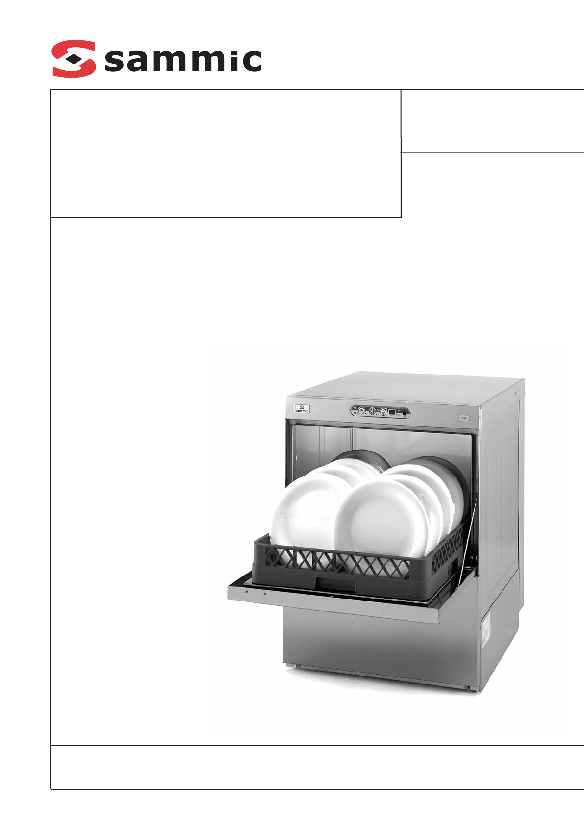
Lavavasos y lavavajillas
Glasswashers and dishwashers
Gläserspülmaschinen und Geschirrspülmaschinen
Lave-verres et lave-vaiselles
Lavatazze e lavastoviglie frontale
Máquinas de lavar copos e máquinas de lavar louça
2
ES
MODELOS
Este manual describe la instalación, funcionamiento y mantenimiento de los lavavajillas: SL360 / SL-360B / SL-360D, SL-560 / SL-560B /
SL-560D y SL-810 / SL-810B.
· Modelos “B”: equipados con bomba de desagüe.
· Modelos “D”: equipados con descalcificador.
La referencia del modelo y sus características
se indican en la placa de identificación colocada en la máquina.
Estas máquinas están diseñadas y fabricadas
de acuerdo con las directivas Europeas de
seguridad 89/392/CEE y 73/23/CEE.
Este aparato cumple con las normas EN55014 y
EN55104 sobre la eliminación e inmunidad de las
perturbaciones radioeléctricas.
INSTALACION
Para obtener las mejores prestaciones y una buena
conservación de la máquina, siga cuidadosamente
las instrucciones contenidas en este manual.
Instalación de agua
Antes de proceder a la instalación de la máquina, compruebe que:
1. La conducción de agua se encuentra a una
distancia inferior a 1,50 m del emplazamiento
previsto para la máquina.
2. La conducción de agua deberá tener en su
extremo más cercano a la máquina una llave
de corte de 3/4'' GAS a la que se conecta la
manguera de alimentación suministrada con
la máquina.
3. La presión dinámica de agua de alimentación
a la máquina no deberá ser ni inferior a 2 bar
(200kPa) ni superior a 4 bar. (400kPa).
Modelos con descalcificador: la presión dinámica de alimentación no deberá ser inferior a
2,5bar (250kPa)
4. El caudal del agua de alimentación debe ser
como mínimo de 15l/min
5. En zonas donde la presión del agua sea mayor
a la máxima indicada, es necesario instalar un
regulador de presión para situar la presión entre
2 y 4 bar (200 y 400kPa).
6. Si la presión del agua es inferior a 2 bar
(200kPa), es necesario instalar un elevador
de presión.
7. Evitar hacer reducciones con la manguera al
hacer la instalación.
8. En los modelos con desagüe por gravedad,
conectar el tubo de desagüe que tiene un diámetro exterior de 30mm, al conducto de desagüe. La altura del desagüe no deberá ser superior a 120 mm desde la base de la máquina.
9. En los modelos "B", provistos de bomba de
desagüe, la altura del desagüe no deberá ser
superior a 1 m desde la base de la máquina.
10. Es necesario nivelar la máquina para permitir
un correcto vaciado, para ello se deben soltar
o apretar las patas niveladoras.
Instalación con descalcificador
Instalar un descalcificador SAMMIC cuando el
contenido de cal en el agua de alimentación de
la máquina sobrepase los 10 ºF. Las instrucciones de instalación acompañan al descalcificador.
Evitar hacer reducciones de caudal (estrangulamientos) antes y después de la instalación, ya
que éstas producen pérdidas de presión.
Instalación con elevador de presión
Instalar un elevador de presión cuando la presión de agua que va alimentar a la máquina sea
inferior a 2 bar. (200kPa). El elevador de presión puede instalarse en cualquier punto cerca
del equipo, prolongando la conducción de agua
y la llave de corte hasta el elevador. Cuidar que
la llave de corte siga estando accesible.
Conectar el levador por un extremo a la llave de
corte y por el otro a la manguera que se suministra con la máquina.
Instalación eléctrica
Máquinas monofásicas (230V/50Hz/1, 220V/60Hz/1):
SL-360
1. Comprobar que el voltaje de la red coincide
con los datos indicados en la placa de características.
2. Instalar un interruptor tipo magnetotérmico de
20A (2P+N). La máquina está equipada con un
cable 3x2,5mm² de sección y 1,70m de longitud que debe ser conectado directamente al
interruptor.
Máquinas trifásicas: SL-560, SL-810
1. Comprobar que el voltaje de la red coincide
con los datos indicados en la placa de características. Las máquinas de serie se suministran conectadas a 400V/3N.
2. Instalar un interruptor tipo magnetotérmico de
25A (3P+N). La máquina está equipada con
un cable 5x2.5 mm² de sección y 1,70m de
longitud que debe ser conectado directamente al interruptor.
3. Cambio de conexiones a 230V/3 fases:
· Desconectar el neutro (cable azul) del cable
de alimentación en la regleta de conexiones.
· Conectar el puente suministrado en la
regleta según el esquema eléctrico.
· Realizar el cambio de conexiones en la
resistencia del calderín, con los puentes
suministrados según el esquema eléctrico.
Máquinas monofasicas: SL-560, SL810 (230/50/1,
220/60/1):
1. Comprobar que el voltaje de la red coincide
con los datos indicados en la placa de características.
2. Instalar un interruptor tipo magneto-térmico
de 40A (2P+N). La máquina está equipada
con un cable 3x6mm² de sección y 1,70m de
longitud que debe ser conectado directamente al interruptor.
Es OBLIGATORIO efectuar la conexión con TIERRA. Además, la máquina está provista de un
tornillo externo para la conexión a un sistema
equipotencial de tierra.
FUNCIONAMIENTO DEL CONTROL
ELECTRÓNICO
Descripción técnica del panel de mandos:
Figura A
VISOR (2)
Al encender la máquina por medio del interruptor general "1", visualiza durante 2 segundos el
modelo de máquina que se haya programado.
A continuación pasa a visualizar la temperatura
de la cuba con la puerta cerrada (piloto "a"
encendido) y del calderin con la puerta abierta
(piloto "b" encendido). Durante el ciclo, visualiza la temperatura de la cuba durante el lavado
y la temperatura del calderin en el aclarado.
TECLA SELECCIÓN DURACIÓN DEL CICLO (3)
Mediante sucesivas pulsaciones de la tecla "3"
se selecciona la duración del ciclo de lavado
entre tres tiempos diferentes: Los pilotos indican el ciclo seleccionado:
"d": Ciclo corto.
"e": Ciclo medio.
"f": Ciclo corto terminado con un aclarado
en frió.
El tipo de ciclo adecuado depende de la suciedad de la vajilla a lavar: a mayor suciedad conviene elegir un ciclo más largo para un lavado
intensivo.
ARRANQUE DEL CICLO (4)
La pulsación de esta tecla arranca el ciclo de
lavado iluminándose el correspondiente piloto
"g". Finalizado el lavado, automáticamente
pasa al aclarado indicado con el piloto "h".
Cuando termina el aclarado la máquina queda

3
ES
en reposo y los indicadores "g" y "h" parpadeando. La apertura de la puerta o arranque de
otro ciclo anula este parpadeo.
En los modelos con bomba de vaciado, durante el final del lavado y antes del aclarado la
máquina realiza el ciclo de vaciado, iluminándose el correspondiente piloto "j".
Pulsando sucesivamente esta tecla se pasa de
una fase a otra del ciclo. Si está en el lavado,
pulsando la tecla, empezamos el aclarado y si
esta aclarando pasa a reposo.
VACIADO (5)
Esta tecla funciona solo en los casos que la
máquina esté provista de una bomba de vaciado.
Únicamente responde a la pulsación cuando la
puerta está abierta. Una vez pulsada (indicador
"j" encendido) empieza el ciclo de vaciado.
Pulsando nuevamente la tecla, se para el ciclo.
Una vez finalizado el vaciado el usuario desconecta la máquina mediante el interruptor general, si no transcurridos unos segundos se inicia
un nuevo llenado.
Ajuste de las Temperaturas de trabajo: (Figura
B esquema placa electrónica)
Las máquinas salen de fábrica ajustadas a:
· Temperatura de Cuba: 55-60ºC
· Temperatura del Calderín: 85-90ºC
Ajuste de temperaturas
· Ajuste temperatura cuba:
1. Con la máquina apagada poner el microruptor 1 de "Desconexión resistencias" (Fig. B-
1) en posición ON (1 ON, 2 OFF).
2. Encender la máquina y esperar hasta que
desaparezca nº de modelo y se visualice una
de las temperaturas en el visor.
3. Pulsar el botón (Fig. B-2) de la placa electrónica hasta que se enciendan los tres pilotos de
selección de ciclo a la vez (Fig. A-d, e, f) y piloto "cuba" (Fig. A-a). Se visualiza la temperatura que tenemos predeterminada en la cuba.
4. Mediante el pulsador "Arranque ciclo" (Fig.
A-4) incrementamos la temperatura de ajuste y con el pulsador "Vaciado" (Fig. A-5) lo
decrementamos.
5. Pulsar "Selección de ciclo" (Fig. A-3) para
memorizar la temperatura elegida. Los tres
pilotos de ciclo se apagan e indica que la
memorización ha sido correcta.
6. Apagar la máquina.
7. Colocar el microruptor 1 de "Desconexión resisten-
cias" (Fig. B-1) en posición OFF (1 OFF, 2 OFF).
· Ajuste temperatura calderin:
1. Con la máquina apagada poner el microruptor 2 de "Desconexión resistencias" (Fig. B 1)
en posición ON (1OFF, 2ON).
2. Encender la máquina y esperar hasta que
desaparezca nº de modelo y se visualice una
de las temperaturas en el visor.
3. Pulsar el pulsador (Fig. B-2) de la placa electrónica hasta que se enciendan los tres leds de
selección de ciclo a la vez (Fig. A-d, e, f) y piloto
"calderin" (Fig. A-b). Se visualiza la temperatura
que tenemos predeterminada en el calderin.
4. Mediante la tecla "Arranque ciclo" (Fig. A-4)
incrementamos la temperatura de ajuste y
con el pulsador "Vaciado" (Fig. A-5) lo decrementamos.
5. Pulsar "Selección de ciclo" (Fig. A-3) para
memorizar la temperatura elegida. Los tres
pilotos de ciclo se apagan e indica que la
memorización ha sido correcta.
6. Apagar la máquina.
7. Colocar el 2 de "Desconexión resistencias"
(Fig. B-1) en posición OFF (1 OFF, 2 OFF).
Desconexión de las resistencias
Para poder anular el calentamiento de las resistencias la placa tiene el doble microinterruptor
"Desconexión resistencias" (Fig. B-1). Por
tanto, poniendo los dos microinterruptores en la
posición "ON" se desconectan las dos resistencias (Desconexión resistencias "ON")
Detección de averías
El acceso a las conexiones de la placa electrónica solo podrá ser realizado por personal de reparación cualificado, tras cortar la corriente eléctrica
con el interruptor general de la máquina y el interruptor automático de protección situado en la
toma exterior de alimentación de la máquina.
En el display se muestran las distintas averías
de las sondas de temperatura de acuerdo al
código siguiente:
· E1:.......Sonda del calderín no conectada (cir-
cuito abierto) Se deben revisar las conexiones
en el conector (Fig. B-c)
· E2:.......Sonda del calderín en cortocircuito:
avería de la sonda que debe ser reemplazada
· E3:.......Sonda de la cuba no conectada (cir-
cuito abierto) Se deben revisar las conexiones
en el conector (Fig. B-c)
· E4:.......Sonda de la cuba en cortocircuito: avería
de la sonda que debe ser reemplazada
En el conector de cuatro pines (Fig. B-C) se
conectan los captadores de temperatura.
La placa electrónica consta de una serie de
indicadores luminosos que son muy útiles a la
hora de ver el funcionamiento de la máquina o
detectar algún fallo. Estos indicadores se dividen en dos grupos, indicadores de entradas y
de salidas:
Leds Indicadores de entrada: Se refieren a la
información que recibe la placa electrónica (Su
posición y descripción se observa en la placa
serigrafiada y en la Figura B), son los siguientes:
Pilotos de color amarillo
· Led "PUERTA": Iluminado puerta cerrada.
· Led "PRESOST": Iluminado presostato acti-
vado, la cuba está llena.
Leds Indicadores de salida: Indica el elemento
que ha sido activado por el microprocesador (Su
posición y descripción se observa en la placa
serigrafiada y en la Figura B), son los siguientes:
Pilotos de color rojo
· Led "B.LAVADO.": Iluminado, bomba de
lavado en funcionamiento.
· Led "B.VAC.": Iluminado, bomba de vaciado
en funcionamiento.
· Led "EV.CAL": Iluminado, electroválvula de
aclarado activada.
· Led "C - CALD." contactor resistencia del cal-
derín: Iluminado, resistencia de calderin activada.
· Led "C - CUBA" Contactor resistencia cuba:
Iluminado, resistencia de la cuba activada.
· Led "EV.FRIA": Iluminado, electroválvula de
aclarado en frió activada.
· Led "EV.REG": Iluminado, electroválvula de
regeneración activada.
Ejemplo: si el led de la resistencia de calderin
está encendido y la resistencia no calienta quiere decir que la placa da la orden de marcha
correctamente, el fallo se encuentra en elementos externos a la placa como podría ser el
rele o la resistencia.
Configuración de modelos:
Control de la duración del ciclo (Enclavamiento
de temperatura) según el calentamiento del
calderín:
· El control electrónico dispone de la opción de
ajustar la duración del ciclo hasta que el calderín haya alcanzado la temperatura prefijada. Es decir, en caso de que el calderín no
hubiera alcanzado la temperatura correcta, el
ciclo continúa hasta que se alcance la temperatura de ajuste. Esto evita que el aclarado se
haga con agua fría. Para seleccionar esta
opción basta elegir el Nº del cuadro adjunto.
Nº
M
ODELO
C
ICLOS
(SG)
B
OMBA
VACIADO
DESCAL-
CIFICADOR
B
LOQUEO
TÉRMICO
DEL CICLO
M
ODELO
1
210
150
120
NO
NO
NO
SL-360
SL-560
SL-810
2 SI
3
SI
NO
SL-360D
SL-560D
SL-810D
4 SI
5
SI
NO
NO
SL-360B
SL-560B
SL-810B
6 SI
7
SI
NO
SL-360BD
SL-560BD
SL-810BD
8 SI
4
ES
Selección del modelo
El número de modelo de máquina aparece en
el display durante 2 segundos desde que se
conecta el interruptor general. Para seleccionar
el número de modelo se debe proceder así:
1. Apagar la máquina
2. Accionar los dos microinterruptores (Fig. B-
1) a la posición "ON" (1ON, 2ON)
3. Encender la máquina
4. Esperar hasta que desaparezca el modelo
seleccionado del display y hasta que aparezca alguna de las temperaturas.
5. Pulsar el pulsador (Fig. B-2) de la placa electrónica hasta que se enciendan los tres pilotos
de selección de ciclo a la vez (Fig. A-d, e, f)
6. Se pulsa "Arranque ciclo" (Fig. A-4) para
incrementar el número de modelo.
7. Se pulsa "Vaciado" (Fig. A-5) para decrementar el número de modelo
8. Una vez seleccionado el número, pulsar la
tecla de selección de ciclo (Fig. A-3) para la
validación. Al memorizar el modelo se apagan
los tres pilotos de ciclo (Fig. A-d, e, f).
9. Apagar la máquina
10. Accionar los dos microinterruptores (Fig. B-
1) a la posición "OFF"
11. Encender la máquina: se visualizará el
número de modelo seleccionado
FUNCIONAMIENTO
Puesta en marcha
1. Abrir la llave de paso del agua 3/4'' GAS.
2. Conectar el interruptor magnetotérmico de
protección de la instalación.
3. Comprobar que los filtros y el rebosadero
indicados en la figura "C" están colocados.
4. Accionar el interruptor general (Fig. A, 1) para
iniciar el llenado automático de la cuba y la
conexión de las resistencias de calentamiento.
5. Cuando la máquina haya alcanzado la temperatura de lavado (55º/60ºC), se ilumina el
piloto (Fig. A, c).
6. Ciclo de arranque:
- Colocar los objetos para lavar en la cesta.
- Cerrar la puerta.
- Seleccionar el programa de lavado pulsando el botón (Fig. A-3), en función del grado
de suciedad. Se encenderá el LED rojo
correspondiente.
- Pulsar la tecla de arranque del ciclo (Fig. A-
4). El indicador luminoso del ciclo de lavado
(Fig. A-g) se enciende. Se realiza el ciclo de
lavado completo. Si estando en el ciclo de
lavado se pulsa de nuevo la tecla de arranque (Fig. A-5), se pasa instantáneamente al
ciclo de aclarado y si está aclarando a la
parada del ciclo.
En los modelos " B" modelos con bomba de
desagüe, durante el final del lavado y antes del
aclarado la máquina realiza el ciclo de vaciado,
iluminándose el correspondiente piloto "j".
7. Una vez acabado el ciclo completo, los dos
pilotos (Fig. A-g) y (Fig. A-h) parpadean indicando el fin del ciclo.
8. Modelos con bomba de vaciado: Con la
puerta abierta y accionando el pulsador (Fig.
A-5) se pone en marcha la bomba de vaciado durante un determinado tiempo que es
suficiente para vaciar la cuba, transcurrido el
cual la bomba se para. Pulsando la tecla
vaciado (Fig. A-5) la bomba arranca y para
alternativamente. Con el rebosadero colocado se vacía el posible exceso de agua acumulada en la cuba.
Dosificador de Detergente
La máquina esta preparada para la instalación
de una bomba dosificadora de detergente regulable, cuyo numero de repuesto se indica en la
lista de repuestos. El dosificador se monta en el
frente inferior delantero según se indica en la
figura del despiece. La máquina dispone de un
orificio en la parte trasera donde se acopla el
racord par la inyección de jabón.
La bomba dosifica aproximadamente 0,7ml/s
de detergente (máximo). En el primer llenado
se inyectan aproximadamente 119ml de detergente en 170s, obteniendo una concentración
máxima de 3 ml/l. En cada ciclo la bomba
inyecta 10ml de detergente. La dosificación se
puede disminuir o aumentar girando el tornillo
de regulación que dispone el dosificador.
Dosificador de abrillantador
Comprobar que el deposito de abrillantador
esta lleno. Poner en macha y parar la bomba de
lavado 5 ò 6 veces mediante sucesivas pulsaciones de la tecla "Arranque ciclo" (Fig. A-4),
comprobando que el tubo de abrillantador se
llena y entra en el calderin. La regulación del
abrillantador se hace mediante el tornillo de
reglaje situado en la parte frontal inferior y
según el sentido indicado.
Para comprobar si la dosis de abrillantador es
eficaz observar los vasos al trasluz. Si hay
gotas de agua en el vidrio la dosis es insuficiente; si aparecen estrías, la dosis es muy alta.
Conjunto de filtros superiores
Para asegurar una correcta limpieza en instalaciones donde el trabajo es intensivo, se puede instalar como accesorio un conjunto de filtros superiores (código indicado en el despiece). Para ello
basta con fijar, mediante unos tornillos, el soporte
de varilla en los agujeros realizados en las guías
de las cestas según se indica en la figura 3.
Los filtros se colocan sobre los soportes.
Desagüe de la máquina
Modelos sin bomba de desagüe: Abrir la puerta
y extraer el rebosadero sin retirar los filtros El
agua cae por gravedad y la suciedad queda
acumulada en los filtros.
Modelos "B" provistos de bomba de desagüe.
· Abrir la puerta y extraer el rebosadero sin retirar los filtros
· Accionar el pulsador de vaciado (Fig. A-5)
según se indica en el panel de mandos, con la
puerta abierta. La bomba de desagüe funciona durante un tiempo programado hasta que se
detiene automáticamente. Pulsando la tecla, la
bomba arranca y para sucesivamente.
· Colocar de nuevo el rebosadero y filtros.
· Desconectar el interruptor general y cerrar la
puerta.
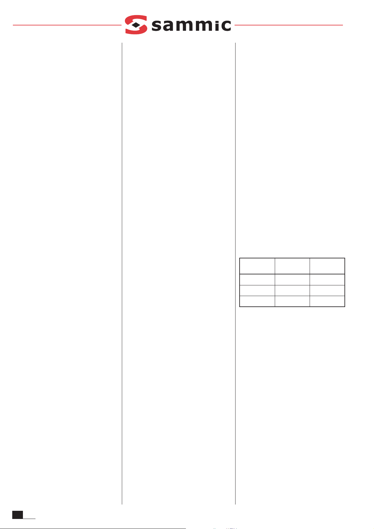
Sistema de descalcificación. Ajuste del
grado de dureza del agua.
En la placa electrónica hay que ajustar el grado
de dureza del agua. La máquina da un aviso de
la regeneración de las resinas mediante el parpado del piloto "regenerar" (Fig. A-k). Este
aviso depende del número de aclarados realizados y del grado de dureza seleccionado. Por
tanto:
1. Con la máquina encendida y en reposo, y estan-
do los dos microruptores de "Desconexión de
Resistencias" (Fig. B-1) en OFF, pulsar el botón
(Fig. B-2) de la placa electrónica.
2. Se enciende uno de los tres pilotos de “dura-
ción de ciclo” (Fig. A, d, e ó f). Según el grado
de dureza del agua los avisos de regeneración se producen:
3. Mediante pulsaciones de "Arranque ciclo"
(Fig. A 4) y "Vaciado" (Fig. A 5) se encienden
sucesivamente los pilotos hasta dejar encendido el grado de dureza seleccionado.
4. Al pulsar tecla "Selección de ciclo" (Fig. A 3)
se memoriza la dureza del agua. El led hace
un parpadeo para indicar que la memorización es correcta.
5. Apagar la máquina.
D
UREZA DE AGUA
A LA ENTRADA
Nº DEC
ICLOS
EQUIVALENTES
(
APROX
.)
P
ILOTO INDICADOR
30º F 90
CICLO CORTO
ENCENDIDO
40º F 70
CICLO MEDIO
ENCENDIDO
50º F 50
CICLO LARGO
ENCENDIDO

5
ES
Sistema de descalcificación. Ciclo de regeneración.
La máquina da un aviso para realizar la regeneración mediante el parpadeo de piloto
"Regeneración" (Fig. A-k). Si el usuario lo considera oportuno, puede realizarlo antes de que
la máquina dé el aviso. Para realizar una regeneración:
1. Desaguar por completo la cuba. MÁQUINA
VACIA SIN REBOSADERO.
2. Con la puerta abierta, al pulsar "Selección de
ciclo" (Fig. A-3) se enciende el piloto
"Regeneración" (Fig. A-k) e indica que se ha
accedido al ciclo de regeneración del sistema
de descalcificación.
3. Cerrar la puerta y pulsar "Arranque ciclo" (Fig.
A 4) para iniciar el ciclo de regeneración.
4. En el visor aparece parpadeando el número
de aclarados realizados y las letras "rn". Al
cabo de 6 sg da comienzo el ciclo de regeneración. Durante estos 6 primeros segundos se puede anular el ciclo de regeneración
volviendo a pulsar "Arranque ciclo" (Fig. A-4).
5. El ciclo de regeneración dura 23 minutos y
no es posible detenerlo. El visor indicará
alternativamente "rd" y el tiempo restante
para final de ciclo, Si se apaga la máquina
durante el ciclo, en el siguiente encendido
nos indicara que es necesario realizar un
nuevo ciclo de regeneración.
6. Cuando en el visor solo aparece "rd" indica
que la regeneración ha acabado.
7. Apagar la máquina para salir de la regeneración.
Sistema de descalcificación. Reposición de
sal para la regeneración.
El acceso al recipiente para la sal de regeneración se encuentra dentro de la cuba de lavado.
Para reponer dicha sal:
1. Desaguar por completo la cuba.
2. Comprobar el recipiente que se encuentra
dentro de la cuba contiene sal (800g). Añadir
si es necesario sal común hasta llenar el recipiente.
3. Consumo de sal por regeneración: 400gr.
4. Duración del depósito de sal: aprox. 2 regeneraciones.
5. Volumen depósito de sal: 800gr.
Vaciado del Calderin
1. Vaciar la cuba
2. Cerrar el paso de agua de alimentación a la
máquina
3. Soltando el tubo que conecta la salida de la
bomba de abrillantador con el tubo de entrada al calderin queda libre este último y colocando un recipiente, sale por gravedad todo
el contenido de agua del calderin.
Limpieza de la cuba
La limpieza de la cuba debe realizarse cada vez
que se termina una sesión de lavado al final del
día. Proceder así:
· Extraer el filtro de seguridad de la bomba de
lavado (L), fijado en bayoneta, girándolo en el
sentido contrario de las agujas del reloj.
· En los modelos "B" con bomba de desagüe
extraer también el filtro de la bomba de desagüe (J), fijado mediante una rosca, para proceder a su limpieza. Según se indica en la
figura 2; girando un cuarto de vuelta se desenrosca el filtro (J). Una vez limpio se enrosca
nuevamente.
· Al final del día conviene vaciar la máquina,
hacer un llenado y realizar un ciclo de lavado
en vacío, sin cestas, de manera que se realice una limpieza del interior de la máquina.
· Limpiar finalmente el fondo, paredes e interior
de la cuba.
· Los brazos de lavado es preciso limpiarlos
periódicamente. Si se observan deficiencias
en el aclarado puede ser debido a la obstrucción de los orificios. En ese caso se deben
soltar y proceder a su limpieza
· El exterior de la máquina NO SE DEBE limpiar
con un chorro directo de agua. Emplear para
su limpieza un paño húmedo y cualquier
detergente habitual.
· NO SE DEBEN utilizar detergentes abrasivos
(aguafuerte, lejía concentrada, etc.), ni estropajos o rasquetas que contengan acero
común, pueden causar la oxidación de la
máquina.
OTRAS OBSERVACIONES IMPORTANTES
· Antes de cualquier intervención para la limpieza o reparación, es obligatorio desconectar la
máquina de la red.
· Cuando el aparato no se utilice durante un
largo período de tiempo, o durante la noche,
se recomienda dejar la puerta abierta para
facilitar la ventilación y evitar malos olores.
· En caso de avería de la bomba de desagüe:
1. Se debe vaciar la cuba mediante un recipiente hasta que el nivel de agua esté por
debajo del rebosadero.
2. Con el rebosadero colocado, soltar el
panel frontal inferior y cambiar la bomba
(es posible realizar esta operación sin
mover la máquina de su emplazamiento).
Si desea vaciar la máquina manualmente,
se debe conectar un tubo de desagüe al
colector. Al retirar el rebosadero, la cuba se
vacía por gravedad.
· Si el cable de alimentación se deteriora y es
preciso instalar uno nuevo, dicho recambio
sólo podrá ser realizado por un servicio técnico reconocido por SAMMIC.
· Ruido aéreo: el ruido emitido por la máquina,
medido sobre una máquina tipo, es de
71dB(A) (distancia 1m).
· Este aparato no esta destinado para ser
usado por personas (incluido niños) cuyas
capacidades físicas, sensoriales o mentales
estén reducidas, o carezcan de experiencia o
conocimiento, salvo si han tenido supervisión
o instrucciones relativas al uso del aparato por
una persona responsable de su seguridad.
6
EN
MODELS
This manual describes the installation, operation and maintenance of the following dishwashers: SL-360 / SL-360B / SL-360D, SL-560 / SL560B / SL-560D and SL-810 / SL-810B.
· “B” Models: equipped with a drainage pump.
· “D” Models: equipped with a de-scaler.
The model reference and its specifications are
shown on the identificacion plate located on the
machine.
These machines have been designed and
manufactured in accordance with the following
European directives for safety: 89/392/EEC and
73/23/EEC.
These appliances comply with the EN55014-1
and EN55104-2 standards for the suppression
and exemption of radio-frequency interferences.
INSTALLATION
For optimum performance and long service life
of the machine, follow the instructions contained in this manual rigorously.
Water connection
Before proceeding with the installation of the
machine, check and make sure that:
1. The mains water connection is within 1.50m
from the foreseen location of dishwasher.
2. At its end on the machine side, the water
supply connection is equipped with a 3/4"
GAS stopcock for the coupling of the water
supply hose supplied with the machine.
3. The dynamic pressure of the water supplied to
the machine is not less than 2 bar (200kPa) and
not greater than 4 bar (400kPa). Models with
water softener: the dynamic pressure of water in
take should not be less than 2.5bar (250kPa).
4. Inlet water flowrate is at least 15l/min.
5. In places where the water pressure is higher
than the specified one, it will be necessary to
incorporate a pressure reducer to bring the
service pressure within the limits of 2 to 4 bar
(200 to 400kPa).
6. Where water pressure is less than 2 bar
(200kPa), it is necessary to install a pressure
booster pump.
7. Avoid bottlenecks with hoses when making
this installation..
8. On models with gravity draining, connect the
drain pipe of an O.D. of 30mm to the sewage
system. The distance from the sewage system
to the machine base shall not exceed 120mm.
9. On models "B" fitted with a drain pump, The
distance from the sewage system to the
machine base shall not exceed 1m.
10. In order to ensure complete drainage, it is
essential that the machine is even. To level
it, undo or screw in the levelling feet.
11. SL-24: The machine is fitted with two water
supply hoses: cold water (25ºC) for the cold
rinse, and hot water (65ºC) for the normal
rinse. These must be connected to their respective water supply inlets. The design of the
hydraulic circuit means that you CANNOT
leave either of the hoses disconnected
because water leaks would occur.
Installation with de-scaler
Install a SAMMIC de-scaler when the limescale
content in the water fed into the machine exceeds
10 ºF. The installation instructions are supplied
with the de-scaler. Avoid reducing the flow rate
(throttling) before and after the installation, as
they can cause a loss of pressure.
Machine installation with a booster pump
Install a pressure booster pump when supply
water pressure is less than 2 bar (200kPa). You
can place the pressure booster pump anywhere
near the appliance, extending the water pipe and
stopcock to the booster pump. Take care that the
stopcock is still accessible. Connect one side of
the booster pump to the stopcock and the other
side to the water supply pipe to the machine.
Electric installation
Single-phase machines (230/50/1; 220/60/1):
SL-360:
1. Check that the mains voltage coincides with
the data indicated on the specification plate.
2. Install a 20A thermomagnetic switch (2P+N).
The machine is equipped with a cable with a
3x2,5mm² cross section and 1,70m length
that must be connected directly to the switch.
Three-phase machines: SL-560, SL810
1. Check that the mains voltage coincides with
the data indicated on the specification plate.
The standard machines are supplied connected to 400V/3N.
2. Install a 25A thermomagnetic switch (3P+N).
The machine is equipped with a cable with a
5x2,5mm² cross section and 1,70m length
that must be connected directly to the switch.
3. Change of connections to 230V/3 phase:
· Disconnect the earth cable (blue) from the
power supply cable in the terminal strip
· Connect the bridge supplied in the terminal
strip according to the electrical diagram
· Change the connections in the boiler resistance, with the bridges supplied according to
the electrical diagram.
Single-phase machines: SL-560, SL810 (230/50/1;
220/60/1):
1. Check that the mains voltage coincides with
the data indicated on the specification plate.
2. Install a 40A thermomagnetic switch (2P+N).
The machine is equipped with a cable with a
3x6mm² cross section and 1,70m length that
must be connected directly to the switch.
EARTHING is OBLIGATORY. Moreover, the
machine includes an external screw for its connection to a ground equipotential system.
OPERATION OF THE ELECTRONIC CONTROLLER
Technical description of the control panel:
Figure A
DISPLAY (2)
After powering up the machine with main switch
(1), the selected machine model appears on the
display for 2 seconds, immediately followed by
the tub temperature if the door is closed (LED
(a) on) or the boiler temperature if the door is
open (LED (b) on). During the cycle, the display
shows the wash tank temperature during the
washing phase and the boiler temperature
during the rinsing phase.
CYCLE TIME SELECTOR (3)
By pushing key (3) repeatedly, you can select
any of three wash cycle times. Light indicators
show the selected cycle:
"d": Short cycle
"e": Medium cycle
"f": Short cycle ending in cold rinsing
Choosing the adequate cycle depends on how
soiled crockery is. The dirtier it is, the longer
the cycle has to be for an intensive, thorough
washing.
STAR T CYCLE (4)
If you press this key, the wash cycle starts and
the associated LED (g) turns on. At the end of
the washing phase, the rinsing process starts
automatically and this is shown by LED (h).
Once rinsing has finished, the machine shifts to
the stand-by condition, with LEDs (g) and (h)
flashing. Flashing stops when the door is opened or a new cycle starts.
On models with a drain pump, the machine performs a draining cycle at the end of the washing
7
EN
phase priot to rinsing. The associated LED (j)
will then turn on.
Press the key repeatedly to move from one
phase of the cycle to another. So, if washing is
on, press the key to shift to the rinsing process.
During rinsing, press the key to put the machine stand-by.
DRAIN (5)
This key works only if the machine has a drain
pump.
It has the desired effect only when the door is
open. Once pushed (LED (j) on), the draining
cycle starts. By pushing the key again, the draining cycle stops.
Upon completion of the draining process, filling
will start again, unless the user has powered
the machine down by turning main switch off.
Adjustment of Working Temperatures: (Figure
B Electronic Boad Diagram)
Temperatures are factory-set at:
· 55-60ºC for the wash tank
· 85-90ºC for the boiler
Setting temperatures:
· SETTING OF WASH TANK TEMPERATURE:
1. With the machine off, set "Disconnect
Resistors" microswitch 1 (Fig. B-1) to position ON (1 ON, 2 OFF).
2. Switch the machine on and wait until the
display stops showing the model number
and shows a temperature.
3. Now press button (Fig. B-2) on the electronic
board until all three 'Select Cycle' LEDs (Fig.
A-d, e, f) and the 'Wash Tank" LED (Fig. A-a)
turn on simultaneously. The display shows
the preset wash tank temperature.
4. Use the pushbutton "Start Cycle" (Fig. A-4) to
increase the temperature setpoint or push
button "Drain" (Fig. A-5) to decrease it.
5. Press "Select cycle" (Fig. A-3) to save the
selected temperature. The three "cycle"
LEDs turn off and the display confirms
correct saving of the value.
6. Switch the machine off.
7. Set "Disconnect Resistors" microswitch 1
(Fig. B-1) to position OFF (1 OFF, 2 OFF).
· SETTING OF BOILER TEMPERATURE:
1. With the machine off, set "Disconnect
Resistors" microswitch 2 (Fig. B-1) to position ON (1 OFF, 2 ON).
2. Switch the machine on and wait until the
display stops showing the model number
and shows a temperature.
3. Now press button (Fig. B-2) on the electronic
board until all three 'Select Cycle' LEDs (Fig.
A-d, e, f) and the 'Boiler" LED (Fig. A-b) turn
on simultaneously. The display shows the
preset boiler temperature.
4. Use the pushbutton "Start Cycle" (Fig. A-4) to
increase the temperature setpoint or push
button "Drain" (Fig. A-5) to decrease it.
5. Press "Select cycle" (Fig. A-3) to save the
selected temperature. The three "cycle"
LEDs turn off and the display confirms
correct saving of the value.
6. Switch the machine off.
7. Set "Disconnect Resistors" microswitch 2
(Fig. B-1) to position OFF (1 OFF, 2 OFF).
Disconnecting the elements
The electronic board includes two "Disconnect
Resistors" microswitches (Fig. B-1) for disabling
the heating of the resistors. Therefore, setting
both microswitches to position ON disconnects
the two elements("Disconnect Resistors" ON).
Troubleshooting
Only qualified technicians may work on the connections of the electronic board, after cutting
out power to the machine with the main switch
and the automatic safety circuit-breaker at the
external feeding point to the machine.
The display shows the temperature probes failure in accordance with the following code:
· E1:.......Boiler probe disconnected (circuit
open). Check the connections at the connector (Fig B-c)
· E2:.......Boiler probe short-circuited. Probe fai-
led and must be changed.
· E3:.......Tub probe disconnected (circuit open).
Check the connections at the connector (Fig B-c)
· E4:.......Tub probe short-circuited. Probe failed
and must be changed.
The temperature transmitters are connected to
the four-pin connector (Fig. B-c).
On the electronic board, there are several light
indicators which are very useful for monitoring
the machine operation and malfunction. Those
indicators belong to either of two groups: input
LEDs or output LEDs.
Input LEDs: those associated with information
received by the electronic board. Their location
and description are indicated on the silk-screened board and on Figure B. The following are
amber LEDs:
· "PUERTA" LED: ON, when the door is closed.
· "PRESOST" LED: ON, when pressure switch
is on, the tub is full.
Output LEDs: They identify the item that has
been activated by the microprocessor. Their
location and description are indicated on the
silk-screened board and on Figure B. The following are red LEDs:
· "B.LAVADO" LED: ON, when wash pump is
working.
· "B.VAC" LED: ON, when drain pump is wor-
king.
· "EV.CAL" LED: ON, when rinsing electroval-
ve is active.
· "C - CALD." LED (boiler element contactor):
ON, when boiler resistor is heating water.
· "C - CUBA" LED (wash tank resistor contac-
tor): ON, when wash tank resistor is heating
water.
· "EV.FRIA" LED: ON, when cold rinsing water
solenoid valve is active.
· "EV.REG" LED": ON, when regeneration
solenoid valve is active.
Example: If the "Boiler Resistor" LED is on and
the resistor does not heat up, this means that the
microprocessor gives the order correctly and the
fault lies in an external item such as the relay or
the resistor.
Model Configuration
Control of cycle time (Thermal Lock) as a
function of the boiler temperature:
· The electronic controller features the possibility of increasing the cycle time until the preset
temperature is reached in the boiler. So, in the
event the temperature of the boiler were lower
than the preset value, the cycle would be
extended until the preset temperature is reached. This prevents rinsing with cold water. In
order to enable this feature, select the appropriate digit from the enclosed table.
Selection of model
The machine model number appears on the
display for 2 seconds once the main switch is
turned on. In order to select another model
number, proceed as follows:
1. Power the machine down.
2. Set the two microswitches (Fig B-1) to posi-
tion "ON" (1ON, 2ON).
3. Power the machine up.
M
ODEL
Nº
C
YCLE
TIME
(
SEC
)
D
RAIN
P
UMP
WATER
SOFTENER
T
HERMAL
LOCK
M
ODEL
1
210
150
120
NO
NO
NO
SL-360
SL-560
SL-810
2
YES
3
YES
NO
SL-360D
SL-560D
SL-810D
4
YES
5
YES
NO
NO
SL-360B
SL-560B
SL-810B
6
YES
7
YES
NO
SL-360BD
SL-560BD
SL-810BD
8
YES
8
EN
4. Wait until the display stops showing the
model number and shows a temperature.
5. Now press button (Fig. B-2) on the electronic
board until all three 'Select Cycle' LEDs (Fig.
A-d, e, f) turn on simultaneously.
6. Use the pushbutton "Start Cycle" (Fig. A-4) to
increase the model number.
7. Push button "Drain" (Fig. A-5) to decrease
the model number.
8. After selecting the desired model number, press
button "Select Cycle" (Fig. A-3) to confirm. The
three "Select Cycle" LEDs (Fig. A-d, e, f) turn off
when the model number has been saved.
9. Power the machine down.
10. Set the two "Disconnect Elements" micros-
witches (Fig. B-1) to position OFF"
11. Power the machine up: the display shows
the selected model number.
OPERATION
Start-up
1.Open the 3/4" stopcock to allow water to enter
the machine.
2. Turn on the magnetothermal switch that protects the installation.
3. Check that the filters and the drain plug are in
place, as Figure "C" shows.
4. Turn the main switch (Fig. A-1) to the ON
position for the automatic filling of the wash
tank and the connection of the heater elements.
5. The light indicator (Fig.A-c) turns on when
the washing temperature (55º/ 60ºC) has
been reached.
6. Start Cycle:
- Place the objects to be washed in a basket
(rack).
- Close the door.
- Select the washing programme by pressing
the button (Fig. A-3) according to the soiling
level. The associated red LED will turn on.
- Press the Start Cycle key (Fig. A-4). The washing phase indicator light (Fig. A-g) turns on.
The machine completes the entire washing
cycle. If you press the Start Cycle key (Fig. A-
5) again during the washing phase, the programme immediately shifts to the rinsing process. Pressing the said key during the rinsing
phase causes the machine to stop.
On models "B" with a drain pump, the machine performs a draining cycle at the end of the
washing phase priot to rinsing. The associated LED (j) will then turn on.
7. When the complete cycle has finished, the
two indicators (Fig. A-g) and (Fig. A-h) flash.
8. Models with a drain pump: With the door
open, press key (Fig. A-5) to start the drain
pump for a given period of time, which is long
enough to empty the tub. At the end of this
time, the pump stops. Press the "Drain" key
(Fig. A-5) to alternately start and stop the
pump. With the drain plug, any residual water
will be removed from the tub.
Detergent dispenser
The glasswasher is prepared for its fitting with an
adjustable detergent dispenser, the part number
of which appears on the spare parts list. This dispenser has to be installed in the machine base, at
the front, as shown on the exploded view. At the
rear of the wash tank, there is an opening where
to insert the detergent injection nozzle.
The dispenser delivers about 0.7ml/s of detergent (maximum). At the first filling of the tank,
feeding of detergent is roughly 119ml in 170s,
resulting in a maximum concentration of 3ml/l.
At each cycle, the dispenser delivers 10ml of
detergent. It is possible to reduce or increase
the injected quantity by turning the adjusting
screw on the dispenser.
Rinsing aid dispenser
Verify that the rinsing aid reservoir is full. Start
and stop the washing water pump 5 or 6 times
by pressing "Start Cycle" (Fig. A-4) and check
whether the tube fills up with rinsing aid and
goes in the boiler. Setting the dispenser is done
by turning an adjusting screw on the front lower
panel in the direction shown on the panel graph.
In order to determine whether the amount of rinsing aid is adequate, look at the glasses against
the light. If there are water droplets on the
glass, the amount of rinsing aid is insufficient; if
streaks develop, the quantity of rinsing aid is
too much.
Set of top filters
To guarantee proper cleanliness in installations
where intensive work is carried out, a set of top
filters can be installed as an accessory (code
indicated in the exploded view). All that has to
be done is to attach, with some screws, the rod
support in the holes made in the basket rails as
shown in figure 3.
The filters are placed on the supports.
Machine Draining
Models with no drain pump: Open the door and
take out the drain plug, leaving the filters in
place. Water will fall by gravity, dirt accumulating in the filters.
Models "B" fitted with a drain pump:
· Open the door and take out the drain plug, leaving the filters in place.
· Press the drain key (Fig. A-5) as specified on
the control panel, with the door open. The
drain pump operates during the programmed
time at the end of which it stops automatically.
By pressing the key, you can successively
start and stop the pump.
· Put the overflow drain plug and filters in place
again.
· Turn the main switch off and close the door.
Water softener. Setting water hardness.
You need to set the water hardness value on
the electronic board. The machine signals that
resin regeneration is needed by means of a
flashing "Regenerate" LED (Fig. A-k). This warning signal depends on the number of rinsing
cycles done and the selected water hardness.
Therefore:
1. With the machine on and idle and both
"Disconnect Resistors" microswitches (Fig.
B-1) set to OFF, press the button (Fig. B-2)
on the electronic board.
2. One of the three “cycle duration” indicators
lights up (Fig. A, d, e or f). Depending on how
hard the water is the regeneration warnings
are activated:
3. Press "Start cycle" (Fig. A-4) and "Drain" (Fig. A-
5) - the LEDs will turn on successively - until you
have the required water hardness selected.
4. Press "Select cycle" (Fig. A-3) to save the
water hardness value. The LED flashes to
confirm correct saving.
5. Switch machine off.
Water softener. Regeneration Cycle.
The machine signals that resin regeneration is
needed by means of a flashing "Regenerate"
LED (Fig. A-k). If you think it proper, you can perform a regeneration cycle before the machine
warns you to do so. In this event, do as follows:
1. Drain the wash tank completely. MACHINE
EMPTY WITHOUT DRAIN PLUG.
2. With the door open, press "Select Cycle" (Fig.
A-3), the "Regeneration" LED (Fig. A-k) turns
on, meaning the machine is ready for the water
softener regeneration cycle.
3. Close the door and press "Start cycle" (Fig.
A-4) to start the regeneration cycle.
4. The display shows the number of rinsing
cycles done and letters "rn" (flashing). The
W
ATER HARDNESS
AT THE INLET
Nº
OF EQUIVALENT
CYCLES
(
APPROX
.)
I
NDICATOR LIGHT
30º F 90
SHORT CYCLE
ON
40º F 70
MEDIUM CYCLE
ON
50º F 50
LONG CYCLE
ON

9
EN
regeneration cycle starts after 6 seconds.
During those 6 seconds, you can stop the
cycle by pressing "Start cycle" (Fig. A-4)
again.
5. This cycle lasts 23 minutes and cannot be
stopped. The display shows "rd" and the time
remaining to end the cycle alternatively. If
you switch the machine off during this cycle,
then on switching it on again, the display will
warn you to do a new regeneration cycle.
6. When the displays shows only "rd", the regeneration cycle has finished.
7. Switch the machine off to quit the regeneration cycle mode.
De-scaling system. Replacement of salt for
regeneration.
Access to the regeneration salt container is inside the washing tank. To replace the salt:
1. Completely drain the tank.
2. Check that the container inside the tank contains salt (800g). Add table salt until the container is full.
3. Consumption of salt per regeneration: 400gr.
4. Duration of the salt deposit: approx 2 regenerations.
5. Volume of salt deposit: 800gr.
Boiler Draining
1. Drain the wash tank.
2. Close the water inlet.
3. Remove the tube coming from the rinsing aid
pump from the inlet connector to the boiler
and place a container under the boiler. All
water flows out of the boiler by gravity.
Tank cleaning
The tank should be cleaned after every washing process, at the end of the day, proceeding
as follows:
· Remove the bayonnet safety filter from the
wash pump (L) by twisting it counterclockwise.
· On models "B" with a drain pump, also remo-
ve the screw-on drain pump filter (J) and
clean it. As figure 2 shows, give the filter (J) a
quarter turn to undo the filter (J). After cleaning the filter, screw it on again.
· At the end of the day, it is advisable to drain the
dishwasher, fill it with water and have a wash
cycle done on no load, without any racks, in
order to clean the interior of the machine.
· Finally, clean the bottom, walls and interior of
the tank.
· Spray arms must be cleaned periodically. If
rinsing is deficient, the cause may be an obstruction of the jets. In this event, dismount the
arms and clean the jets.
· The outside of the machine MUST NOT BE
washed under a direct water jet; instead you
can use a wet cloth and any ordinary detergent.
· DO NOT USE any abrasive detergent (etchant,
concentrated lye, etc.) nor any scourer or scraper containing normal steel that will cause rust
to develop on the machine.
OTHER IMPORTANT REMARKS
· Before cleaning, servicing or repairing the
machine, it is necessary to unplug it from the
mains.
· When the appliance is going to be inactive for
a long period of time or at night, the door
should be kept open for aeration and avoiding
nasty smell.
· In case of a drain pump failure:
1.Drain the wash tank into a container until
the water level drops below the drain plug.
2.With the drain plug in place, remove the
front bottom panel and change the pump
(this can be done without moving the machine). In order to drain the machine manually,
connect a drain hose to the collector. On
pulling out the drain plug, water flows out of
the tank by gravity.
· In the event the power supply cable should
get damaged and have to be replaced, the
repair may only be done by a SAMMIC approved assistance service.
· Airborne noise: the emission noise level measured on a typical machine is 71 dB(A) at a
distance of 1m.
· This machine is not designed to be used by
individuals (including children) with reduced
physical, sensorial or mental facilities, or who
lack the relevant experience or knowledge,
unless they are supervised by or have received instruction on how to use the apparatus
from a person responsible for their safety.

MODELLE
Die vorliegende Anleitung beschreibt die Installation,
Bedienung und Instandhaltung folgender
Geschirrspüler: SL-360 / SL-360B / SL-360D, SL560 / SL-560B / SL-560D und SL-810 / SL-810B.
· Modelle "B": mit Entwässerungspumpe.
· Modelle "D": mit Wasserenthärter.
Modell-Nr. und Merkmale sind auf dem
Typenschild an der Maschine angegeben.
Diese Maschinen sind gemäss den europäischen
Sicherheitsrichtlinien 89/392/EWG und 73/23/EWG
entworfen und hergestellt worden.
Dieses Gerät entspricht den Vorschriften
EN55014 und EN55104 über radioelektrische
Entstörung und Immunität.
INSTALLATION
Um eine einwandfreie Leistung und lange
Lebensdauer der Maschine sicherzustellen,
befolgen Sie bitte genau die in diesem
Handbuch enthaltenen Hinweise.
Wasseranschluss
Bevor Sie die Maschine installieren, prüfen Sie
bitte folgendes:
1. Der Wasseranschluss muss sich in einem
Abstand von weniger als 1,50 m von dem für
die Maschine vorgesehenen Aufstellungsort
befinden.
2. Die Wasserleitung muss an dem Ende, welches der Maschine am nächsten liegt, mit
einem Absperrhahn ¾" GAS ausgestatter
sein, an den der an der Maschine befindliche
Zulaufschlauch angeschlossen wird.
3. Der dynamische Wasserdruck der Netzleitung
zur Maschine sollte nicht niedriger als 2 bar
(200 kPa) und nicht höher als 4 bar (400 kPa)
sein. Modelle mit Wasserenthärter: der
Staudruck Wasserzuführ wird nicht weniger
als 2,5bar (250kPa).
4. Die Wasserdurchflussmenge muss mindestens 15l/min betragen.
5. An Orten, wo der maximal zulässige Druck
überschritten wird, muss ein Druckregler eingebaut werden, der den Druck auf 2 bis 4
bar (200 - 400 kPa) einstellt.
6. Wenn der Druck niedriger als 2 bar (200kPa) ist,
muss ein Druckerhöhungsgerät eingebaut werden.
7. Vermeiden Sie Reduzierungen beim
Anschliessen des Schlauches.
8. Bei den Modellen mit Schwerkraftentwässerung
wird das Abflussrohr, das einen Aussendurchmesser
von 30 mm hat, an die Abflussleitung angeschlossen. Der Abfluss darf nicht höher als 120
mm über der Maschinengrundplatte liegen.
9. Bei den "B"-Modellen, die mit Entwässerungspumpe
ausgestattet sind, darf der Abfluss nicht höher
als 1 m über der Maschinengrundplatte liegen.
10. Für eine einwandfreie Entwässerung muss
die Maschine gut ausgerichtet sein.
Verwenden Sie hierzu je nach Erfordernis die
an der Maschine vorhandenen Nivellierfüsse.
Installation mit Wasserenthärter
Einen SAMMIC-Wasserenthärter installieren,
wenn der Kalkgehalt des Wassers, das der
Maschine zugeführt wird, über 10 ºF beträgt. Die
Installationsanleitung liegt dem Wasserenthärter
bei.
Eine Durchflussverringerung (Leitungsengpässe)
vor und hinter der Installation vermeiden, da
diese einen Druckverlust verursachen.
Installation mit Druckerhöhungsgerät
Wenn das Leitungswasser zur Versorgung der
Maschine einen Druck von weniger als 2 bar (200
kPa) aufweist, muss ein Druckerhöhungsgerät
eingebaut werden. Das Gerät kann an einer
beliebigen Stelle der Ausrüstung eingebaut werden, indem man die Wasserleitung mit dem
Absperrhahn bis zum Druckerhöhungsgerät verlängert. Achten Sie darauf, dass der Absperrhahn
zugänglich bleibt. Das Gerät wird an einem Ende
an den Absperrhahn angeschlossen und am
anderen Ende an den mitgelieferten Schlauch an
der Maschine.
Elektroinstallation
Maschinen mit Einphasenmotor (230/50/1;
220/60/1): SL-360
1. Sicherstellen, dass die Leitungsspannung
die auf dem Typenschild angegebenen
Spezifikationen erfüllt.
2. Einen Leitungsschutzschalter mit 20 A (2P+N)
installieren. Die Maschine ist mit einem Kabel
mit einem Durchmesser von 3 x 2,5 mm² und
einer Länge von 1,70 m ausgestattet, das
direkt an den Schalter angeschlossen wird.
Maschinen mit Dreiphasenmotor: SL-560, SL810
1. Sicherstellen, dass die Leitungsspannung
die auf dem Typenschild angegebenen
Spezifikationen erfüllt. Die Maschinen werden serienmäßig mit einem Anschluss an
400V/3N geliefert.
2. Einen Leitungsschutzschalter mit 25 A (3P+N)
installieren. Die Maschine ist mit einem Kabel
mit einem Durchmesser von 5 x 2,5 mm² und
einer Länge von 1,70 m ausgestattet, das
direkt an den Schalter angeschlossen wird.
3. Anschlusswechsel zu 230 V/3 Phasen:
· Den Neutralleiter (blaues Kabel) auf der
Anschlussleiste vom Netzanschlusskabel abziehen.
· Das mitgelieferte Patchkabel gemäß
Schaltschema an der Anschlussleiste anschließen
· Den Anschlusswechsel am Behälterwiderstand
vornehmen, dabei die mitgelieferten
Patchkabel gemäß dem Schaltschema anschließen.
Maschinen mit Einphasenstrom: SL-560,
SL810 (230/50/1; 220/60/1):
1. Sicherstellen, dass die Leitungsspannung
die auf dem Typenschild angegebenen
Spezifikationen erfüllt.
2. Einen Leitungsschutzschalter mit 40 A
(2P+N) installieren. Die Maschine ist mit
einem Kabel mit einem Durchmesser von 3 x
6 mm² und einer Länge von 1,70 m ausgestattet, das direkt an den Schalter angeschlossen wird.
Der ERDANSCHLUSS ist OBLIGATORISCH.
Ausserdem kann die Maschine über eine aussen am Gerät angebrachte Schraube zum
Potentialausgleich benutzt werden.
BETRIEBSWEISE DER ELEKTRONISCHEN
STEUERUNG
Technische Beschreibung der Schalttafel:
Abb. A
ANZEIGE (2)
Wenn man mit dem Hauptschalter "1" die
Maschine einschaltet, erscheint hier 2 Sekunden
lang das Modell der einprogrammierten
Maschine. Anschliessend wird die Temperatur in
der Spülkammer mit geschlossenem Deckel
(Kontrolllampe "a" leuchtet) und die Temperatur im
Kessel bei offenem Deckel (Kontrolllampe "b"
leuchtet) angegeben. Während des Zyklus wird
die Spülkammertemperatur beim Spülen und die
Kesseltemperatur beim Klarspülen angezeigt.
TASTE FÜR DIE WAHL DER ZYKLUSDAUER (3)
Mit der Taste "3" kann man drei verschiedene
Zeiten für die Zyklusdauer auswählen. Die
Kontrolllampen zeigen den jeweils gewählten
Zyklus an, und zwar
"d": kurzer Zyklus
"e": normaler Zyklus
"f": kurzer Zyklus, der mit einer kalten
Klarspülung abschliesst.
Die Zyklusdauer richtet sich nach dem
Verschmutzungsgrad des zu spülenden Geschirrs:
Bei stärkerer Verschmutzung ist für ein intensiveres Spülen ein längerer Zyklus zu empfehlen.
10
DE

ZYKLUSSTART (4)
Ein Druck auf diese Taste startet den Spülzyklus
und die entsprechende Kontrolllampe "g" leuchtet
auf. Nach dem Spülen schaltet die Maschine
automatisch auf Klarspülen, das mit der
Kontrolllampe "h" angezeigt wird. Nach
Abschluss des Klarspülvorganges bleibt die
Maschine in Ruhestellung und die
Anzeigelampen "g" und "h" blinken. Das Blinken
erlischt, sobald man die Tür öffnet oder einen
neuen Zyklus startet.
Bei den Modellen mit Entwässerungspumpe findet am Ende des Spülvorganges und vor dem
Klarspülen der Entwässerungszyklus statt, der
mit der entsprechenden Kontrolllampe "j" angezeigt wird.
Durch erneutes Betätigen der Taste kann man
von einer Zyklusetappe auf die nächste wechseln, also vom Spülvorgang auf Klarspülen und
vom Klarspülen auf Ruhestellung.
ENTWÄSSERN (5)
Diese Taste ist nur wirksam, wenn die Maschine
mit einer Entwässerungspumpe ausgerüstet ist.
Sie reagiert nur auf den Druck, wenn die Tür
offen ist. Nach dem Druck auf die Taste
(Anzeigelampe "j" leuchtet) beginnt der
Entwässerungszyklus.
Nach abgeschlossener Entwässerung kann der
Benutzer Maschine mit dem Hauptschalter
ausschalten. Andernfalls beginnt nach einigen
Sekunden wieder das Einfüllen von Wasser.
Einstellen der Betriebstemperaturen (Abb. B
Leiterbild)
Die Maschinen sind vom Werk aus wie folgt eingestellt:
· Spülkammertemperatur: 55-60ºC
· Kesseltemperatur: 85-90ºC
Regulieren der Temperaturen:
· EINSTELLEN DER SPÜLKAMMERTEMPERATUR:
1. Stellen Sie bei abgeschalteter Maschine den
Mikroschalter 1 für "Widerstände ausschalten" (Abb. B-1) auf die Position ON (1 ON, 2
OFF).
2. Maschine einschalten und warten bis die
Modell-Nr. verschwindet und eine der
Temperaturen auf der Anzeige erscheint.
3. Den Knopf (Abb. B-2) der Elektronikplatte
drücken, bis die drei Kontrolllampen für
Zykluswahl gleichzeitig leuchten (Abb. A-d, e, f)
sowie ebenfalls die Lampe für "Spülkammer"
(Abb. A-a). Die für die Spülkammer vorgegebene Temperatur wird angezeigt.
4. Mit der Drucktaste "Zyklusstart" (Abb. A-4)
können wir die eingestellte Temperatur erhö-
hen und mit der Taste "Entwässern" (Abb. A-
5) können wir sie verringern.
5. Zum Abspeichern der gewählten Temperatur
drücken Sie auf "Zykluswahl" (Abb. A-3). Die
drei Kontrolllampen für Zyklus erlöschen was
bedeutet, dass das Abspeichern einwandfrei
erfolgt ist.
6. Maschine abschalten.
7. Stellen Sie den Mikroschalter 1 für
"Widerstände ausschalten" (Abb. B-1) auf die
Position OFF (1 OFF, 2 OFF).
· EINSTELLEN DER KESSELTEMPERATUR:
1. Stellen Sie bei abgeschalteter Maschine den
Mikroschalter 2 für "Widerstände ausschalten"
(Abb. B-1) auf die Position ON (1 OFF, 2 ON).
2. Maschine einschalten und warten bis die
Modell-Nr. Verschwindet und eine der
Temperaturen auf der Anzeige erscheint.
3. Den Knopf (Abb. B-2) der Elektronikplatte
drücken, bis die drei Leds für Zykluswahl
gleichzeitig leuchten (Abb. A-d, e, f) sowie
ebenfalls die Lampe für "Kesselr" (Abb. A-b).
Die für den Kessel vorgegebene Temperatur
wird angezeigt.
4. Mit der Drucktaste "Zyklusstart" (Abb. A-4)
können wir die eingestellte Temperatur erhöhen und mit der Taste "Entwässern" (Abb. A-
5) können wir sie verringern.
5. Zum Abspeichern der gewählten Temperatur
drücken Sie auf "Zykluswahl" (Abb. A-3). Die
drei Kontrolllampen für Zyklus erlöschen was
bedeutet, dass das Abspeichern einwandfrei
erfolgt ist.
6. Maschine abschalten.
7. Stellen Sie den Schalter 2 für "Widerstände
abschalten" (Abb. B-1) auf die Position OFF
(1 OFF, 2 OFF).
Abschalten der Widerstände
Um das Erhitzen der Widerstände zu unterbrechen verfügt die Platte ubre den doppelten
Mikroschalter "Widerstände abschalten" (Abb. B-
1). Wenn man die beiden Mikroschalter auf "ON"
stellt, schalten sich die beiden Widerstände ab
(Widerstände abschalten "ON").
Fehlersuche
Der Zugang zur elektronischen Leiterplatte ist
nur qualifiziertem Fachpersonal gestattet. Vor
jedem Eingriff muss mit dem Hauptschalter
sowie mit dem automatischen Schutzschalter
am aussen an der Maschine vorhandenen
Steckanschluss die Stromzufuhr zur Maschine
unterbrochen werden.
Auf der Anzeige werden die verschiedenen
Störungen der Temperatursensoren gemäss
dem nachstehenden Kode aufgezeigt:
· E1: ..... Kesselsensor nicht angeschlossen
(Kreis offen). Anschlüsse an der
Steckvorrichtung nachprüfen (Abb. B-c)
· E2: ..... Kesselsensor in Kurzschluss: Störung
am Sensor, der ausgetauscht werden muss
· E3:..... Spülkammersensor nicht angeschlos-
sen (Kreis offen). Anschlüsse an der
Steckvorrichtung nachprüfen (Abb. B-c)
· E4:..... Spülkammersensor in Kurzschluss:
Störung am Sensor, der ausgetauscht werden
muss.
Die Temperaturfühler werden an der 4 PinSteckvorrichtung (Abb. B-c) angeschlossen.
Die elektronische Leiterplatte enthält eine Reihe
von Leuchtanzeigen, die zur Funktionsüberwachung
der Maschine sowie zum Feststellen von Störungen
sehr nützlich sind. Diese Leuchtanzeigen sind
in zwei Gruppen, d.h. Eingänge und Ausgänge,
aufgeteilt:
Eingangs-Leds: Diese Leds beziehen sich auf
die Information, die die elektronische Leiterplatte
empfängt (die Position und Beschreibung ist aus
der Serigraphieplatte und aus der Abbildung B
ersichtlich). Es handelt sich um folgende Leds in
gelber Farbe:
· Led "PUERTA": leuchtet, die Tür ist ges-
chlossen
· Led "PRESOST": leuchtet, Druckwächter ist
aktiviert, die Spülkammer ist voll.
Ausgangs-Leds: Angabe des Elementes, das
durch den Mikroprozessor aktiviert worden ist
(Lage und Beschreibung geht aus der serigraphierten Platte und aus der Abbildung B hervor). Es handelt sich um folgende rote
Kontrollampen:
· Led "B.LAVADO": leuchtet, Spülpumpe in
Betrieb
· Led "B.VAC": leuchtet, Entwässerungspumpe in
Betrieb
· Led "EV.CAL": leuchtet, E-Ventil Klarspülen
aktiviert
· Led "C - CALD": Schaltschütz Widerstand
Kessel, leuchtet, Kesselwiderstand aktiviert
· Led "C - CUBA" Schaltschütz Widerstand
Spülkammer: leuchtet, Widerstand der
Spülkammer aktiviert
· Led "EV.FRIA": leuchtet, E-Ventil kaltes
Klarspülen aktiviert
· Led "EV.REG": leuchtet, E-Ventil für
Regenerieren aktiviert
Beispiel: Wenn die Led des Kesselwiderstands
leuchtet und der Widerstand sich nicht erhitzt
bedeutet dies, dass die Platte den Befehl zum
Betrieb richtig übermittelt und dass ein Fehler an
den Elementen ausserhalb der Platte vorliegt, wie
z.B am Schaltschütz oder am Widerstand.
11
DE

Gestaltung der Modelle:
Kontrolle der Zyklusdauer (Temperatursperre,
Thermal Lock) je nach Aufheizung des
Kessels:
Die elektronische Steuerung bietet die
Möglichkeit, die Zyklusdauer auf die vorbestimmte Kesseltemperatur einzustellen. Das
heisst, dass der Zyklus so lange andauert, bis
im Kessel die vorbestimmte Temperatur erreicht
ist. Dadurch wird verhindert, dass mit kaltem
Wasser klargespült wird. Diese Option kann mit
der entsprechenden Nummer in der beigefügten Tabelle angewählt werden.
Modellauswahl
Sobald man den Hauptschalter einschaltet, erscheint auf der Anzeige 2 Sekunden lang die
Modell-Nr. Zum Anwählen der Modell-Nr. Ist folgendes zu tun:
1. Maschine abschalten
2. Die beiden Mikroschalter (Abb. B-1) auf die
Position "ON" (1ON, 2ON) stellen
3. Maschine einschalten
4. Warten, bis das gewählte Modell von der
Anzeige verschwindet und bis eine der
Temperaturen erscheint.
5. Den Knopf (Abb. B-2) der Elektronikplatte
drücken, bis die drei Kontrolllampen für
Zykluswahl gleichzeitig leuchten (Abb. A-d, e, f)
6. Mit einem Druck auf "Zyklusstart" (Abb. A-4)
erhöhen Sie die Modell-Nr.
7. Der Knopf "Entwässern" (Abb. A-5) dient zum
Verringern der Modell-Nr.
8. Nach Auswählen der Nummer drücken Sie zur
Bestätigung auf die Taste für Zykluswahl (Abb.
A-3). Beim Abspeichern der Modell-Nr. erlöschen die drei Zyklus-Leds (Abb. A-d, e, f).
9. Maschine abschalten.
10. Die beiden Mikroschalter (Abb. B-1) auf die
Position "OFF" stellen.
11. Maschine einschalten: Die gewählte Modell-
Nr. Wird angezeigt.
BETRIEB
Inbetriebnahme
1. Den.3/4" GAS-Wasserhaupthahn aufdrehen.
2. Den Thermomagnetschutzschalter der
Anlage einschalten.
3. Nachprüfen, ob die in der Abbildung "C" dargestellten Filter und der Überlauf richtig
angebracht sind.
4. Hauptschalter (Abb.A, 1) einschalten, so
dass das automatische Befüllen der
Spülkammer einsetzt und die Widerstände
zur Erwärmung des Wassers eingeschaltet
werden.
5. Sobald das Wasser die Spültemperatur (55º/60º
C) erreicht hat, leuchtet die Kontrolllampe
(Abb.A-e) auf.
6. Anlaufzyklus:
- Verteilen Sie das Geschirr im Korb.
- Schliessen Sie die Tür.
- Wählen Sie mit dem Knopf (Abb. A-2) das
gewünschte Spülprogramm aus.
- Drücken Sie auf die Taste für Zyklusstart (A-
4). Die Leuchtanzeige des Spülzyklus (A-g)
leuchtet auf. Der Spülzyklus läuft nun vollständig ab. Bei einem erneuten Druck auf die
Anlauftaste (A-5) während des
Spülvorganges springt das Programm direkt
auf den Klarspülzyklus über. Das Gleiche
geschieht vom Klarspülzyklus auf
Zyklusstopp.
Bei den B-Modellen mit Entwässerungspumpe
findet am Ende des Spülvorganges und vor dem
Klarspülen ein Entwässerungszyklus statt, bei
dem die entsprechende Led "j" aufleuchtet.
7. Wenn der Zyklus vollständig abgelaufen ist,
blinken die Kontrolllampen (A-g) und (A-h)
und zeigen so das Zyklusende an.
8. Modelle mit Entwässerungspumpe. Wenn
man bei offenem Deckel die Drucktaste (Abb.
A-5) betätigt, setzt sich die Pumpe für eine
bestimmte Zeit in Gang die ausreicht, um die
Spülkammer zu entleeren, und bleibt dann
stehen. Bei Betatigen der Taste für
Entwässern (Abb. A-5) schaltet die Pumpe
abwechselnd ein und aus. Wenn der Überlauf angebracht ist, wird das eventuell überschüssige Wasser aus der Spülkammer abgelassen.
Spülmitteldosierer
Die Maschine ist für den Einbau einer verstellbaren Spülmitteldosierpumpe vorgesehen,
deren Ersatzteilnummer in der Ersatzteilliste
angegeben ist. Der Dosierer wird - wie auf der
Einzelteilzeichnung zu sehen ist - an der
Frontseite unten angebracht. An einer Öffnung
an der Rückseite der Maschine wird der
Schraubanschluss zum Einspritzen des
Spülmittels angebracht.
Die Pumpe dosiert etwa 0,7ml/s Spülmittel
(max.). Bei der ersten Füllung werden in 170 s
etwa 119 ml Spülmittel eingespritzt, so dass
eine Konzentration von max. 3 ml/l entsteht. Bei
jedem Spülzyklus spritzt die Pumpe 10 ml
Spülmittel ein. Zum Verringern oder Erhöhen
der Dosierung wird die Regulierschraube des
Dosierers entsprechend gedreht.
Glanzmitteldosierer
Prüfen Sie nach, ob der Glansmittelbehälter voll
ist. Setzen Sie 5 oder 6-mal die Pumpe in
Gang, indem Sie mehrmals auf die Taste
"Zyklusstart" (Abb. A-4) drücken und prüfen Sie,
ob der Glansmittelschlauch in den Kessel eindringt. Mit der Stellschraube vorne unten kann
man die Glanzmittelmenge einstellen.
Prüfen Sie die richtige Glanzmitteldosierung,
indem Sie die Gläser unter Licht betrachten.
Wassertropfen auf dem Glas bedeuten, dass zu
wenig Glanzmittel dosiert wird; wenn Streifen
zu sehen sind, ist die Dosierung zu hoch.
Oberfilter-Set
Um eine korrekte Reinigung von Installationen
mit intensiver Beanspruchung zu gewährleisten,
kann als Zubehör ein Oberfilter-Set installiert werden (Bestell-Nr. siehe Explosionszeichnung).
Hierzu wird der Stahlständer wie in Abb. 3 gezeigt
in den zu diesem Zweck vorgesehenen
Bohrungen in den Korbführungen festgeschraubt.
Die Filter werden auf den Ständern montiert.
Entwässern der Maschine
Modelle ohne Entwässerungspumpe: Den
Deckel öffnen und den Überlauf herausziehen
ohne die Filter zu entfernen.
Das Wasser läuft durch Schwerkraft heraus und
der Schmutz bleibt in den Filtern zurück.
"B"-Modelle mit Entwässerungspumpe
· Den Deckel öffnen und den Überlauf heraus-
ziehen ohne die Filter zu entfernen
· Die Entwässerungstaste (Abb. A-5) betätigen,
und zwar bei offenem Deckel, wie auf der
Schalttafel angegeben ist. Die
Entwässerungspumpe arbeitet während einer
bestimmten vorgegebenen Zeit und bleibt
automatisch stehen. Mit einem Druck auf die
Taste können Sie die Pumpe abwechselnd
ein- und ausschalten.
· Überlauf und Filter wieder anbringen.
· Den Hauptschalter abschalten und den
Deckel schliessen.
Entkalkungssystem. Regulieren der Wasserhärte.
Der Härtegrad des Wassers muss auf der
Elektronikplatte eingestellt werden. Die Maschine
gibt einen Hinweis über die Regeneriegung der
Harze, indem die Kontrolllampe "Regenerieren"
12
DE
M
ODELL
N
R
Z
YKLEN
(S)
E
NTWÄS
S
.
PUMPE
ENTKALKER
T
EMPER
.
SPERRE
DES
Z
YKLUS
M
ODELL
1
210
150
120
NEIN
NEIN
NEIN
SL-360
SL-560
SL-810
2
JA
3
JA
NEIN
SL-360D
SL-560D
SL-810D
4
JA
5
JA
NEIN
NEIN
SL-360B
SL-560B
SL-810B
6
JA
7
JA
NEIN
SL-360BD
SL-560BD
SL-810BD
8
JA

(Abb. A-k) blinkt. Dieser Hinweis ist abhängig von
der Anzahl der durchgeführten Klarspülungen und
von dem ausgewählten Härtegrad. Daher:
1. Wenn die Maschine eingeschaltet und in
Ruhestellung ist und die beiden Mikroschalter
für "Widerstände abschalten" (Abb.. B-1) auf
OFF stehen, drücken Sie bitte auf den Knopf
(Abb. B-2) der elektronischen Leiterplatte.
2. Eine der drei Kontrolllampen der
"Zyklusdauer" leuchtet auf (Abb. A, d, e oder
f). Je nach Wasserhärte werden die folgenden Regenerierungsmeldungen angezeigt:
3. Bei Betätigen von "Zyklusstart" (Abb. A 4)
und "Entwässern"(Abb. A 5) leuchten nacheinander die Leds auf, bis der angewählte
Härtegrad leuchtet.
4. Bei Betätigen der Taste "Zykluswahl" (Abb. A
3) wird die Wasserhärte abgespeichert. Die
Led blinkt um anzuzeigen, dass das
Abspeichern erfolgreich war.
5. Maschine abschalten.
Entkalkungssystem. Regeneriegungszyklus.
Zur Durchführung der Regenerierung gibt die
Maschine einen Hinweis durch das Blinken der
Kontrolllampe "Regenerieren " (Abb. A-k). Wenn
er es für angebracht hält, kann der Benutzer das
Regenerieren vornehmen, bevor die Maschine
darauf hinweist. Zum Regenerieren ist folgendes
zu tun:
1. Die Spülkammer total entwässern. MASCHI-
NE LEER OHNE ÜBERLAUF.
2. Wenn man bei offenem Deckel auf
"Zykluswahl" (Abb. A-3) drückt, leuchtet die
Kontrolllampe "Regenerieren" (Abb. A-k) auf.
Das bedeutet, dass wir in den
Regenerierungszyklus des
Entkalkungssystems eingestiegen sind.
3. Den Deckel schliessen und auf "Zyklusstart"
drücken (Abb. A-4), um den
Regeneriegungszyklus einzuleiten.
4. Auf der Anzeige erscheint blinkend die Anzahl
der durchgeführten Klarspülungen und die
Buchstaben "rn". Nach etwa 6 Sekunden
beginnt der Regenerierungszyklus. Während
dieser ersten 6 Sekunden kann man mit einem
Druck auf "Zyklusstart" (Abb. 4-4) den Zyklus
anhalten
5. Der Regenerierungszyklus dauert 23
Minuten und kann nicht unterbrochen werden. Auf der Anzeige erscheint alternativ "rd"
und die bis zum Zyklusende verbleibende
Zeit. Wird die Maschine während des Zyklus
abgeschaltet, so wird beim nächsten
Einschalten darauf hingewiesen, dass ein
neuer Regenerierungszyklus ausgeführt werden muss.
6. Wenn auf der Anzeige nur "rd" erscheint, ist
die Regenerierung fertiggestellt.
7. Maschine abschalten, um das Regenerieren
zu verlassen.
Entkalkungssystem. Salzauffüllung für die
Regenerierung.
Der Zugriff auf den Regeneriersalzbehälter befindet sich in der Spülwanne. Vorgehensweise zum
Auffüllen des Salzes:
1. Das Wasser vollständig aus der Spülwanne
ablassen.
2. Prüfen, ob der Behälter in der Spülwanne
Salz enthält (800 g). Ggf. mit Mineralsalz auffüllen, bis der Behälter voll ist.
3. Salzverbrauch pro Regenerierung: 400 g.
4. Gebrauchslebensdauer pro Salzfüllung: ca. 2
Regenerierungszyklen.
5. Füllvolumen des Salzes: 800 g.
Entleeren des Kessels
1. Spülkammer entleeren
2. Den Wasserzulaufhahn zur Maschine
schliessen.
3. Durch Lösen des Schlauches, welcher den
Ausgang der Glanzmittelpumpe mit dem
Eintrittsschlauch zum Kessel verbindet, wird
dieser letztere freigelegt. Stellen Sie einen
Behälter darunter. Der gesamte Kesselinhalt
kann nun durch Schwerkraft ablaufen.
Reinigen der Spülkammer
Nach jeder Spülschicht am Tagesende muss
die Spülkammer gereinigt werden. Dies geschieht wie folgt:
· Den mit einem Bajonettverschluss angebrach-
ten Sicherheitsfilter der Spülpumpe (L) durch
Drehen entgegen dem Uhrzeigersinn herausnehmen.
· Bei den "B"-Modellen mit Entwässerungspumpe
muss auch der Filter der Entwässerungspumpe
(J), der eingeschraube ist, zum Reinigen herausgenommen werden. Wie aus der Abb. 2 hervorgeht, kann der Filter (J) mit einer viertel
Umdrehung herausgeschraubt werden. Nach
dem Reinigen wieder einschrauben.
· Am Ende des Tages sollte man die Maschine
entleeren, Wasser einfüllen und einen Zyklus
im Leerlauf, ohne Körbe, ausführen, damit das
Innere der Maschine gereinigt wird.
· Schlussendlich werden Boden, Seitenwände
und Spülraum von innen gereinigt.
· Die Spülarme müssen regelmässig gereinigt
werden. Ein unzureichendes Spülen kann auf
verstopfte Löcher zurückzuführen sein. Die
Arme müssen dann abmontiert und gesäubert
werden.
· Das Äussere der Maschine darf NICHT
DIREKT mit einem Wasserstrahl gereinigt
werden. Benutzen Sie lediglich ein feuchtes
Tuch und ein gewöhnliches Putzmittel.
· Benutzen Sie bitte KEINE ätzenden Putzmittel
(Radierwasser, konzentrierte Chlorlauge usw.)
noch Scheuerschwämme oder Kratzer, die
normalen Stahl enthalten, da diese ein Rosten
der Maschine verursachen können.
WICHTIGE HINWEISE
· Vor jedem Eingriff zur Reinigung oder
Reparatur der Maschine muss unbedingt der
Netzanschluss unterbrochen werden.
· Immer wenn das Gerät für längere Zeit oder
während der Nacht nicht benutzt wird empfiehlt es sich, den Deckel offen zu lassen,
damit der Innenraum gelüftet wird und keine
unangenehmen Gerüche entstehen können.
· Im Falle einer Störung an der Entwässerungspumpe:
1. Mit Hilfe eines Behälters Wasser aus der
Spülkammer schöpfen, bis der
Wasserspiegel unterhalb des Überlaufes
steht.
2. Bei angebrachtem Überlauf das untere
vordere Paneel lösen und die Pumpe auswechseln (hierzu braucht die Maschine
nicht von ihrem Platz gerückt zu werden).
Soll die Maschine von Hand geleert werden, so muss ein Entwässerungsschlauch
an den Kollektor angeschlossen werden.
Sobald der Überlauf entfernt wird, läuft das
Wasser durch Schwerkraft aus der
Spülkammer ab.
· Wenn das Zuleitungskabel beschädigt ist und
erneuert werden muss, so darf diese Arbeit
nur von einer von SAMMIC anerkannten
Technischen Dienststelle ausgeführt werden.
· Geräuschpegel: Der von der Maschine abgegebene an einer Grundtype gemessene
Geräuschpegel beträgt 71dB(A) (in 1 m
Abstand).
· Dieses Gerät darf nicht von Personen
(einschl. Kindern) benutzt werden, die in ihren
körperlichen, sensorischen oder geistigen
Fähigkeiten behindert sind oder nicht über die
erforderliche Erfahrung und Kenntnis verfügen, es sei denn sie sind von einer für ihre
Sicherheit verantwortliche Person in den
Gebrauch des Gerätes eingewiesen oder
dabei überwacht worden.
13
DE
W
ASSERHÄRTE
E
INGANG
E
NTSPRECHENDE
Z
YKLUSANZAHL
(N
ÄHERUNGSWERT
)
K
ONTROLLLAMPE
30º F 90
KURZER ZYKLUS
EINGESCHALTET
40º F 70
MITTLERER ZYKLUS
EINGESCHALTET
50º F 50
LANGER ZYKLUS
EINGESCHALTET

MODÈLES
Ce manuel décrit l’installation, le fonctionnement et la maintenance des lave-vaisselle:
SL-360 / SL-360B / SL-360D, SL-560 / SL-560B /
SL-560D et SL-810 / SL-810B.
· Modèles « B »: équipés d’une pompe de vidange.
· Modèles « D »: équipés d’un adoucisseur.
La référence et les caractéristiques du modèle
sont indiquées sur la plaque signalétique fixée
sur la machine.
Ces machines sont conçues et fabriquées conformément aux directives européennes de
sécurité 89/392/CEE et 73/23/CEE.
Ces appareils répondent aux normes EN55014
et EN55104 relatives à l'élimination et l'immunité des perturbations radioélectriques.
INSTALLATION
Pour obtenir les performances optimales et
assurer une bonne conservation de la machine,
veuillez respecter les instructions contenues
dans cette notice.
Installation d'eau
Avant de procéder à l'installation de la machine,
contrôler les points suivants :
1. La conduite d'arrivée d'eau doit se trouver à
une distance de moins de 1,50 m de l'emplacement prévu pour la machine.
2. La conduite d'eau doit être équipée à son
extrémité la plus proche de la machine d'un
robinet d'arrêt de 3/4" GAZ pour le raccordement du tuyau d'alimentation fourni avec la
machine.
3. La pression dynamique d'eau d'alimentation de
la machine ne doit être ni inférieure à 2 bar
(200 kPa) ni supérieure à 4 bar (400 kPa).
Modèles avec adoucisseurs: la pression dynamique de la prise d'eau ne doit pas être inférieure à 2,5bar (250kPa).
4. Le débit de l'eau d'alimentation doit être au
moins de 15l/min.
5. Dans les régions où la pression de l'eau est
supérieure au maximum indiqué, il est nécessaire d'installer un régulateur de pression pour
maintenir la pression comprise entre 2 et 4 bar
(200 et 400 kPa).
6. Si la pression de l'eau est inférieure à 2 bar
(200kPa), il est nécessaire de prévoir un surpresseur.
7. Eviter les rétrécissements de tuyau lors de
l'installation.
8. Sur les modèles à vidange par gravité, raccorder le tuyau de vidange qui a un diamètre extérieur de 30 mm, à la conduite de vidange. La
hauteur de vidange ne doit pas être supérieure
à 120 mm de la base de la machine.
9. Sur les modèles "B" équipés d'une pompe de
vidange, la hauteur de vidange ne doit pas être
supérieure à 1 m de la base de la machine.
10. Pour assurer une bonne vidange, la machi-
ne doit être mise correctement de niveau en
vissant ou dévissant les pieds de réglage.
Installation avec adoucisseur
Installer un adoucisseur SAMMIC lorsque le
taux de calcaire contenu dans l’eau d’alimentation de la machine est supérieur à 10 °F. Les
instructions d’installation sont fournies avec l’adoucisseur.
Il convient d’éviter de réduire le débit (étranglements) en amont et en aval de l’installation, car
cela engendre des pertes de pression.
Installation avec surpresseur
Installer un surpresseur lorsque la pression de
l'eau d'alimentation de la machine est inférieure à 2 bar (200 kPa). Le surpresseur peut être
installé en n'importe quel point proche de l'équipement, dans le prolongement de la conduite d'eau et du robinet d'arrêt situé en amont du
surpresseur. Veillez à ce que le robinet d'arrêt
reste toujours accessible. Raccorder le surpresseur d'un côté au robinet d'arrêt et de l'autre au tuyau flexible fourni avec la machine.
Branchement électrique
Machines monophasées (230/50/1; 220/60/1):
SL-360
1. Vérifier que le voltage du réseau correspond
aux données indiquées sur la plaquette d’identification.
2. Installer un interrupteur de type magnétothermique de 20A (2P+N). La machine est fournie
avec un câble 3x2,5mm2 de section et 1,70 m
de longueur, qui doit être directement connecté à l’interrupteur.
Machines triphasées : SL-560, SL810
1. Vérifier que le voltage du réseau correspond
aux données indiquées sur la plaquette d’identification. Les machines de série sont livrées
connectées à 400V/3N.
2. Installer un interrupteur de type magnétothermique de 25A (3P+N). La machine est fournie
avec un câble 3x2,5mm2 de section et 1,70 m
de longueur, qui doit être directement connecté à l’interrupteur.
3. Modification des connexions à 230V/3 phases :
· Déconnecter le neutre (fil bleu) du câble d’a-
limentation sur la réglette de connexion.
· Connecter le pont fourni sur la réglette en sui-
vant le schéma électrique.
· Effectuer le changement de connexions sur
la résistance de la chaudière avec les ponts
fournis en suivant le schéma électrique.
Machines monophasées : SL-560, SL810
(230/50/1; 220/60/1):
1. Vérifier que le voltage du réseau correspond
aux données indiquées sur la plaquette d’identification.
2. Installer un interrupteur de type magnétothermique de 40A (2P+N). La machine est fournie
avec un câble 3x6mm2 de section et 1,70 m de
longueur, qui doit être directement connecté à
l’interrupteur.
La MISE A LA TERRE est OBLIGATOIRE. La
machine est pourvue d'une vis externe pour le
raccordement à la liaison équipotentielle de terre.
FONCTIONNEMENT DE LA COMMANDE
ÉLECTRONIQUE
Description technique du panneau de commande :
Figure A
ECRAN D'AFFICHAGE (2)
A l'allumage de la machine à l'aide de l'interrupteur général "1", l'affichage montre pendant 2
secondes le modèle de machine programmé.
Puis il visualise la température de la cuve avec
la porte fermée (voyant "a" allumé) et du surchauffeur avec la porte ouverte (voyant "b" allumé). Pendant le cycle, il montre la température
de la cuve lors du lavage et la température du
surchauffeur lors du rinçage.
TOUCHE SÉLECTION DURÉE DU CYCLE (3)
Par pressions successives sur la touche "3", on
sélectionne la durée du cycle de lavage entre
trois durées différentes. Les voyants s'allument
pour indiquer le cycle choisi :
"d" : Cycle court.
"e" : Cycle moyen.
"f" : Cycle court se terminant par un
rinçage à froid.
Le type de cycle à choisir dépend du degré de
saleté de la vaisselle : plus elle est sale, plus le
cycle doit être long pour un lavage intensif.
DÉPART CYCLE (4)
La pression sur cette touche met en marche le
cycle de lavage. Le voyant "g" associé s'allume.
Au terme du lavage, la machine passe automa-
14
FR

tiquement au rinçage (voyant "h" allumé).
Lorsque le rinçage est terminé, la machine s'arrête et les voyants "g" et "h" clignotent.
L'ouverture de la porte ou le démarrage d'un
nouveau cycle annule ce clignotement.
Sur les modèles équipés d'une pompe de
vidange, la machine effectue le cycle de vidange à la fin du lavage et avant le rinçage. Le
voyant "j" associé s'allume.
Par pressions successives sur cette touche, on
passe d'une phase à l'autre du cycle : si on est
en lavage, la pression sur la touche fait passer
au rinçage et si on est en rinçage, on passe à
l'état de repos.
VIDANGE (5)
Cette touche n'est active que sur les machines
équipées d'une pompe de vidange.
La pression sur la touche n'est valide que si la
porte est ouverte. Lorsque la touche est appuyée (indicateur "j" allumé), le cycle de vidange
démarre. Une nouvelle pression sur la touche
arrête le cycle de vidange.
Au terme de la vidange, l'utilisateur doit éteindre la machine à l'aide de l'interrupteur général.
Sinon, au bout de quelques secondes, un nouveau remplissage commence.
Réglage des températures de fonctionnement :
(Figure B schéma plaque électronique).
Les machines sont réglées en usine aux températures suivantes :
· Température Cuve : 55-60ºC
· Température Surchauffeur : 85-90ºC
Réglage des températures :
· RÉGLAGE TEMPÉRATURE CUVE :
1. La machine étant éteinte, mettre le microrupteur 1 de "Débranchement résistances" (Fig.
B-1) sur la position ON (1 ON, 2 OFF).
2. Allumer la machine et attendre la disparition
du nº de modèle et l'apparition d'une des
indications de température sur l'affichage.
3. Appuyer sur le bouton (Fig. B-2) de la plaque
électronique jusqu'à l'allumage des trois
voyants de sélection de cycle en même
temps (Fig. A-d, e, f) et du voyant "cuve" (Fig.
A-a). L'écran affiche alors la température
préfixée pour la cuve.
4. Appuyer sur le bouton poussoir "Départ
cycle" (Fig. A-4) pour augmenter la température de réglage et sur le bouton poussoir
"Vidange" (Fig. A-5) pour la diminuer.
5. Appuyer sur "Sélection cycle" (Fig. A-3) pour
mémoriser la température choisie. Les trois
voyants de sélection de cycle s'éteignent
pour indiquer que la mise en mémoire s'est
faite correctement.
6. Eteindre la machine.
7. Remettre le microrupteur 1 de "Débranchement
résistances" (Fig. B-1) sur la position OFF (1
OFF, 2 OFF).
Réglage température surchauffeur :
1. La machine étant éteinte, mettre le microrup-
teur 2 de "Débranchement résistances" (Fig.
B-1) sur la position ON (1 OFF, 2 ON).
2. Allumer la machine et attendre la disparition
du nº de modèle et l'apparition d'une des
indications de température sur l'affichage.
3. Appuyer sur le bouton (Fig. B-2) de la plaque
électronique jusqu'à l'allumage des trois
voyants de sélection de cycle en même
temps (Fig. A-d, e, f) et du voyant "surchauffeur" (Fig. A-b). L'écran affiche alors la température préfixée pour le surchauffeur.
4. Appuyer sur le bouton poussoir "Départ
cycle" (Fig. A-4) pour augmenter la température de réglage et sur le bouton poussoir
"Vidange" (Fig. A-5) pour la diminuer.
5. Appuyer sur "Sélection cycle" (Fig. A-3) pour
mémoriser la température choisie. Les trois
voyants de sélection de cycle s'éteignent
pour indiquer que la mise en mémoire s'est
faite correctement.
6. Eteindre la machine.
7. Remettre le microrupteur 2 de "Débranchement
résistances" (Fig. B-1) sur la position OFF (1
OFF, 2 OFF).
Débranchement des résistances
Pour pouvoir annuler le chauffage des résistances, la plaque est munie de deux microrupteurs
"Débranchement résistances" (Fig. B-1). Les
microrupteurs doivent être mis tous deux sur la
position "ON" pour débrancher les deux résistances (Débranchement résistances : "ON")
Détection des pannes
L'accès aux branchements de la plaque électronique n'est autorisé qu'à des réparateurs qualifiés, après coupure du courant électrique à l'aide
de l'interrupteur général de la machine et de l'interrupteur automatique de protection situé sur la
prise d'alimentation extérieure de la machine.
L'écran affiche les différentes défaillances possibles des sondes de température, conformément au code suivant :
· E1 :.......Sonde du surchauffeur non branchée
(circuit ouvert). Contrôler les branchements
sur le connecteur (Fig. B-c).
· E2 :.......Sonde du surchauffeur en court-cir-
cuit : défaillance de la sonde qui doit être remplacée.
· E3 :.......Sonde de la cuve non branchée (cir-
cuit ouvert). Contrôler les branchements sur le
connecteur (Fig. B-c).
· E4 :.......Sonde de la cuve en court-circuit :défai-
llance de la sonde qui doit être remplacée.
Les détecteurs de température sont branchés
sur le connecteur à quatre broches (Fig. B-c).
La plaque électronique regroupe une série d'indicateurs lumineux qui sont très utiles pour la
surveillance du fonctionnement de la machine
et pour la détection des éventuelles défaillances. Ces indicateurs se divisent en deux groupes : ceux d'entrée et ceux de sortie.
Leds indicatrices d'entrée : Elles concernent
les informations qui sont reçues par la plaque
électronique (Leur position et leur description
figurent sur la plaque sérigraphiée et sur la figure B). Ce sont les suivantes (Voyants jaunes) :
· Led "PUERTA" : Allumée lorsque la porte est
fermée.
· Led "PRESOST" : Allumée lorsque le pressos-
tat est activé, indiquant que la cuve est pleine.
Leds indicatrices de sortie : Elles indiquent
l'élément qui a été mis en marche par le microprocesseur (Leur position et leur description
figurent sur la plaque sérigraphiée et sur la figure B). Ce sont les suivantes (Voyants rouges) :
· Led "B.LAVADO" : Allumée lorsque la pompe
de lavage est en marche.
· Led "B.VAC" : Allumée lorsque la pompe de
vidange est en marche.
· Led "EV.CAL" : Allumée lorsque l'électrovan-
ne de rinçage est activée.
· Led "C - CALD" contacteur résistance sur-
chauffeur : Allumée lorsque la résistance du
surchauffeur est en marche.
· Led "C - CUBA" contacteur résistance cuve
: Allumée lorsque la résistance de la cuve est
en marche.
· Led "EV.FRIA" : Allumée lorsque l'électrovan-
ne de rinçage à l'eau froide est activée.
· Led "EV.REG" : Allumée lorsque l'électrovan-
ne de régénération est activée.
Exemple : Si la led de la résistance du surchauffeur est allumée et que la résistance n'est
pas en marche, cela veut dire que la plaque a
bien donné l'ordre de marche, mais qu'il y a une
défaillance au niveau des éléments externes de
la plaque, tels que le relais ou la résistance.
Configuration des modèles :
Réglage de la durée du cycle (Verrouillage température) sur la température du surchauffeur :
· La commande électronique possède une
option permettant de régler la durée du cycle
sur le moment où la température préfixée est
atteinte par le surchauffeur. C'est-à-dire que le
cycle continue tant que le surchauffeur n'a pas
atteint la température préfixée. Ceci permet d'é-
15
FR

viter que le rinçage soit réalisé à l'eau froide.
Pour sélectionner cette option, il suffit de choisir le Nº indiqué dans le tableau ci-dessous.
Sélection du modèle
A la mise sous tension par l'interrupteur général,
le numéro du modèle de machine apparaît pendant 2 secondes sur l'affichage. Pour sélectionner le numéro de modèle, procéder comme suit :
1. Eteindre la machine.
2. Basculer les deux microrupteurs (Fig B-1)
sur la position "ON" (1ON, 2ON).
3. Allumer la machine.
4. Attendre la disparition du nº de modèle et
l'apparition d'une des indications de température sur l'affichage.
5. Appuyer sur le bouton poussoir (Fig. B-2) de
la plaque électronique jusqu'à l'allumage des
trois voyants de sélection de cycle en même
temps (Fig. A-d, e, f)
6. Appuyer sur "Départ cycle" (Fig. A-4) pour
incrémenter le numéro de modèle.
7. Appuyer sur "Vidange" (Fig. A-5) pour décrémenter le numéro de modèle.
8. Après avoir sélectionné le numéro voulu,
valider en appuyant sur la touche de sélection du cycle (Fig. A-3). Les trois voyants de
sélection cycle s'éteignent après la mise en
mémoire du modèle (Fig. A-d, e, f).
9. Eteindre la machine.
10. Basculer de nouveau les deux microrup-
teurs (Fig. B-1) sur la position "OFF".
11. Rallumer la machine : le numéro de modèle
sélectionné est affiché.
FONCTIONNEMENT
Mise en marche
1. Ouvrir le robinet d'arrivée d'eau 3/4'' GAZ.
2. Basculer l'interrupteur magnétothermique de
protection de l'installation.
3. Vérifier que les filtres et le dispositif de tropplein indiqués sur la figure "C" sont en place.
4. Basculer l'interrupteur général (Fig. A-1) pour
démarrer le remplissage automatique de la
cuve et mettre en marche les résistances de
chauffage.
5. Lorsque la machine a atteint la température de
lavage (55º/60ºC), le voyant (Fig. A- c) s'allume.
6. Cycle de démarrage :
- Disposer la vaisselle dans le panier.
- Fermer la porte.
- Sélectionner le programme de lavage par
pression sur le bouton (Fig. A-3), en fonction du degré de saleté de la vaisselle. La
led rouge associée s'allume.
- Appuyer sur la touche de départ cycle (Fig.
A-4). Le voyant lumineux du cycle de lavage (Fig. A-g) s'allume. Le cycle de lavage
complet est exécuté. Si pendant le cycle de
lavage, on appuie de nouveau sur la touche
de départ cycle (Fig. A-5), la machine
passe immédiatement au cycle de rinçage
et si elle est en cours de rinçage, elle se
met en arrêt cycle.
Sur les modèles "B" dotés d'une pompe de
vidange, la machine réalise le cycle de vidange à la fin du lavage et avant le rinçage. Le
voyant lumineux "j" associé s'allume.
7. Lorsque le cycle complet est terminé, les
deux voyants (Fig. A-g) et (Fig. A-h) clignotent pour indiquer la fin de cycle.
8. Modèles avec pompe de vidange : la porte
étant ouverte, appuyer sur le bouton poussoir
(Fig. A-5) pour mettre en marche la pompe
de vidange. La pompe reste en marche pendant un temps déterminé qui est suffisant
pour vidanger l'eau de la cuve, puis elle s'arrête. La pression sur la touche de vidange
(Fig. A-5) commande alternativement la mise
en marche et l'arrêt de la pompe. Le dispositif de trop-plein permet de vidanger l'éventuel
excédent d'eau au fond de la cuve.
Doseur de Produit de Lavage
La machine est préparée pour l'installation
d'une pompe de dosage réglable du produit de
lavage. La référence de cette pompe est indiquée dans la liste des pièces détachées. Le
doseur est à monter sur le panneau avant inférieur de la machine, comme montré sur la vue
éclatée. La machine possède un trou à la partie
arrière pour le raccordement du dispositif d'injection du produit de lavage.
La pompe débite environ 0,7 ml/s de liquide de
lavage (maximum). Lors du premier remplissage de la cuve, la dose est d'environ 119 ml en
170 s, afin d'obtenir une concentration maximum de 3 ml/l. A chaque cycle, la pompe distribue 10 ml de produit de lavage. Cette quantité
peut être diminuée ou augmentée en tournant
la vis de réglage du doseur.
Doseur de Produit de rinçage
Vérifier que le réservoir de produit de rinçage
est plein. Mettre en marche et arrêter la pompe
de lavage 5 ou 6 fois, en appuyant par pressions successives sur la touche "Départ cycle"
(Fig. A-4), afin de vérifier que le tuyau du
doseur se remplit correctement de produit et
que celui-ci entre dans le surchauffeur. Le
réglage de la quantité de produit de rinçage se
fait en tournant la vis de réglage située sur le
panneau avant inférieur de la machine, dans le
sens qui convient.
Pour vérifier si la dose de produit de rinçage est
efficace, regarder les verres à contre-jour. Si
des gouttes d'eau apparaissent sur les verres,
la quantité de produit est insuffisante ; s'il y a
des stries, c'est qu'elle est trop importante.
Ensemble des filtres supérieurs
Pour garantir un nettoyage idoine sur les installations où le travail est intensif, vous pouvez
installer en tant qu’accessoire complémentaire
un ensemble de filtres supérieurs (le code est
indiqué sur la liste des pièces). Pour cela il suffit de fixer, par le biais de quelques vis, le support de tige dans les trous présents sur les guides des paniers, tel qu’indiqué sur la figure 3.
Les filtres doivent être placés sur les supports.
Vidange de la machine
Modèles sans pompe de vidange : Ouvrir la
porte et ôter le trop-plein sans enlever les filtres. L'eau s'écoule par gravité et les saletés
sont retenues par les filtres.
Modèles "B" équipés d'une pompe de vidange.
· Ouvrir la porte et ôter le trop-plein, sans enlever les filtres.
· La porte étant ouverte, appuyer sur le bouton
poussoir de vidange (Fig. A- 5), comme indiqué
sur le tableau de commande. La pompe de
vidange fonctionne pendant le temps préfixé,
puis elle s'arrête automatiquement. A chaque
pression sur la touche, on commande alternativement la mise en marche et l'arrêt de la pompe.
· Remettre en place le trop-plein et les filtres.
· Basculer l'interrupteur général sur arrêt et
refermer la porte.
Système d'adoucissement. Réglage du degré
de dureté de l'eau.
Le réglage du degré de dureté de l'eau doit être
effectué sur la plaque électronique. Le voyant
"Régénération" (Fig. A-k) clignote pour prévenir
que la régénération des résines est nécessaire.
La régénération dépend du nombre de rinçages
effectués et du degré de dureté sélectionné.
Procéder comme suit :
1. La machine étant allumée et au repos, les
deux microrupteurs de "Débranchement
Résistances" (Fig. B-1) sur OFF, appuyer sur le
bouton (Fig. B-2) de la plaque électronique.
16
FR
Nº
M
ODÈLE
C
YCLES
(S)
P
OMPE
VIDANGE
ADOUCISSEUR
B
LOCAGE
THERMIQUE
M
ODÉLE
1
210
150
120
NON
NON
NON
SL-360
SL-560
SL-810
2
OUI
3
OUI
NON
SL-360D
SL-560D
SL-810D
4
OUI
5
OUI
NON
NON
SL-360B
SL-560B
SL-810B
6
OUI
7
OUI
NON
SL-360BD
SL-560BD
SL-810BD
8
OUI

2. On allume un des trois pilotes de « durée de
cycle » (Fig. A, d, e ou f). En fonction du niveau de dureté de l’eau, les messages de régénération s’affichent :
3. Appuyer sur les boutons "Départ cycle" (Fig.
A 4) et "Vidange" (Fig. A 5), les voyants s'allument successivement. Sélectionner le
degré de dureté voulu.
4. Appuyer sur la touche "Sélection cycle" (Fig.
A 3) pour mémoriser la dureté de l'eau choisie. La led clignote pour indiquer que la
mémorisation s'est faite correctement.
5. Eteindre la machine.
Système d'adoucissement. Cycle de régénération.
Le témoin "Régénération" (Fig. A-k) clignote
pour prévenir que le système nécessite une
régénération. Si l'utilisateur le juge utile, il peut
déclencher une régénération avant le clignotement du voyant témoin. Pour déclencher une
régénération :
1. Vidanger complètement la cuve. MACHINE
VIDE SANS TROP-PLEIN.
2. La porte étant ouverte, appuyer sur
"Sélection cycle" (Fig. A-3) : le voyant
"Régénération" (Fig. A-k) s'allume pour indiquer qu'on a accédé au cycle de régénération du système d'adoucissement.
3. Fermer la porte et appuyer sur "Départ
cycle" (Fig. A-4) pour lancer le cycle de régénération.
4. L'indication du nombre de rinçages réalisés
et les lettres "rn" clignotent sur l'affichage.
Au bout de 6 s, le cycle de régénération
démarre. Pendant ces 6 premières secondes, il est possible d'arrêter le cycle de
régénération en appuyant de nouveau sur
"Départ cycle" (Fig. A-4).
5. Le cycle de régénération dure 23 minutes et
il est impossible de l'arrêter en cours d'exécution. L'affichage indique alternativement
"rd" et le temps restant pour la fin du cycle. Si
l'on éteint la machine pendant l'exécution du
cycle, à son rallumage, une indication apparaît rappelant qu'il est nécessaire d'exécuter
un nouveau cycle de régénération.
6. La régénération est terminée lorsque seule
l'indication "rd" apparaît sur l'affichage.
7. Eteindre la machine pour quitter la régénération.
Système d’adoucissement. Ajout de sel
pour la régénération.
L’accès au récipient du sel de régénération se
trouve à l’intérieur de la cuve de lavage. Pour
ajouter du sel :
1. Vidanger entièrement la cuve.
2. Le récipient qui se trouve dans la cuve doit contenir 800 g de sel. Ajouter si nécessaire du sel
ordinaire jusqu’à remplir le récipient.
3. Consommation de sel par régénération : 400gr.
4. Durée du récipient de sel : environ 2 régénérations.
5. Volume du récipient de sel : 800gr.
Vidange du Surchauffeur
1. Vidanger la cuve.
2. Fermer le robinet d'arrivée d'eau.
3. Déposer le tuyau reliant la sortie de la pompe
de liquide de rinçage au tuyau d'entrée dans
le surchauffeur. Ce dernier est alors libre et,
en prenant la précaution de mettre dessous
un récipient, toute l'eau du surchauffeur s'écoule par gravité.
Nettoyage de la cuve
La cuve doit être nettoyée tous les jours au
terme de l'utilisation de la machine. Procéder
comme suit :
· Enlever le filtre de sécurité de la pompe de
lavage (L) fixé par baïonnette, en le tournant
dans le sens contraire des aiguilles d'une
montre.
· Sur les modèles "B" à pompe de vidange,
enlever également le filtre de la pompe de
vidange (J) fixé par vissage et procéder à son
nettoyage. Pour dévisser le filtre (J), le tourner
d'un quart de tour, comme indiqué sur la figure 2. Nettoyer le filtre puis le revisser.
· A la fin de la journée, il convient de vider la
machine, puis de la remplir d'eau et d'exécuter
un cycle de lavage à vide, sans panier, de
manière à bien nettoyer l'intérieur de la machine.
· Nettoyer pour finir le fond, les parois et l'inté-
rieur de la cuve.
· Les bras de lavage doivent être nettoyés régu-
lièrement. Une mauvaise qualité du rinçage
peut être due à des orifices bouchés. Dans ce
cas, démonter et nettoyer les bras de lavage.
· La carrosserie de la machine NE DOIT PAS
ÊTRE nettoyée au jet sous pression. La nettoyer avec un torchon humide et un nettoyant
courant.
· NE PAS utiliser de détergents agressifs (aci-
des, eau de javel non diluée, etc.), ni d'éponges métalliques ou de raclettes en acier susceptibles de provoquer la formation de rouille.
AUTRES OBSERVATIONS IMPORTANTES
· Avant toute intervention sur la machine (nettoyage ou réparation), il est impératif de débrancher la prise du secteur.
· Pendant la nuit ou en cas de non-utilisation
prolongée de l'appareil, il est recommandé de
laisser la porte ouverte afin d'assurer son
aération et éviter les mauvaises odeurs.
· En cas de défaillance de la pompe de vidange :
1. En s'aidant d'un récipient, vidanger l'eau
de la cuve jusqu'à ce que le niveau d'eau
reste en dessous du trop-plein.
2. Le trop-plein étant laissé en place, déposer
le panneau avant inférieur et remplacer la
pompe (il n'est pas nécessaire de déplacer
la machine pour cette opération). Pour
vidanger la machine à la main, raccorder
un tuyau de vidange au collecteur. Lorsque
le trop-plein est enlevé, l'eau s'écoule de la
cuve par gravité.
· Si le cordon d'alimentation est endommagé et
qu'il a besoin d'être changé, son remplacement doit être impérativement effectué par un
service technique agréé par SAMMIC.
· Bruit aérien : le niveau sonore émis par la
machine, mesuré sur une machine type, est
de 71 dB(A) (distance 1 m).
· Cet appareil n'est pas destiné à être utilisé par
des personnes (y compris des enfants) dont
les capacités physiques, sensorielles ou mentales sont diminuées, ou qui ne disposent pas
des connaissances ou de l'expérience nécessaires, à moins qu'elles n'aient été formées et
encadrées pour l'utilisation de cet appareil par
une personne responsable de leur sécurité.
17
FR
D
URETÉ
DE L
’
EAU À
L
’
ENTRÉE
N
BRE DE CYCLES
ÉQUIVALENTS
(
ENVIRON
)
P
ILOTE INDICATEUR
30º F 90
CYCLE COURT
ALLUMÉ
40º F 70
CYCLE MOYEN
ALLUMÉ
50º F 50
CYCLE LONG
ALLUMÉ

MODELLI
Questo manuale descrive l'installazione, il funzionamento e la manutenzione delle lavastoviglie: SL-360 / SL-360B / SL-360D, SL-560 / SL560B / SL-560D e SL-810 / SL-810B.
· Modelli “B”: muniti di pompa di scarico.
· Modelli “D”: muniti di decalcificatore.
Il riferimento del modello e delle sue caratteristiche vengono riportati sulla targa di identificazione apposta sulla macchina.
Queste macchine vengono disegnate e fabbricate d'accordo con le direttive Europee sulla
sicurezza 89/392/CEE e 73/23/CEE.
Questo apparecchio adempie le norme
EN55014 e EN55104 sull'abolizione e l'immunità delle interferenze radioelettriche.
INSTALLAZIONE
Per ottenere le migliori prestazioni ed una buona
conservazione della macchina, seguire attentamente le istruzioni contenute in questo manuale.
Installazione dell'acqua
Prima di provvedere all'istallazione della macchina, verificare che:
1. La condotta dell'acqua si trovi a una distanza
inferiore di 1,50 m. dall'ubicazione prevista
per la macchina.
2. La condotta dell'acqua dovrà avere nel suo
estremo più vicino alla macchina un rubinetto d'interruzione di 3/4'' GAS a cui si collega
il manicotto di alimentazione fornito con la
macchina.
3. La pressione dinamica dell'acqua di alimentazione della macchina non dovrà essere né
inferiore a 2 bar (200kPa), né superiore a 4
bar (400kPa). Modelli con addolcitori: la
pressione dinamica della presa di acqua non
sarà inferiore a 2,5bar (250kPa).
4. La portata dell'acqua di alimentazione deve
essere come minimo di 15l/min.
5. In zone in cui la pressione dell'acqua è maggiore di quella massima indicata, è necessario installare un regolatore di pressione, per situare
detta pressione fra i 2 ed i 4 bar (200 e 400kPa).
6. Se la pressione dell'acqua è inferiore ai 2 bar
(200kPa), è necessario installare un elevatore di pressione.
7. Al realizzare l'installazione, evitare di eseguire la riduzione con il manicotto.
8. Nei modelli con scolo per gravità, collegare il
tubo di scolo che ha un diametro esterno di
30mm, alla condotta di scolo. L'altezza dello
scolo non dovrà essere superiore ai 120 mm
a partire dalla base della macchina.
9. Nei modelli "B" provvisti di pompa di scolo,
l'altezza dello scolo non dovrà essere superiore a 1 m. a partire dalla base della macchina.
10. È necessario livellare la macchina per per-
mettere uno scarico corretto; allo scopo si
devono allentare o stringere i piedi di livellamento.
Installazione con decalcificatore
Installare un decalcificatore SAMMIC quando il
contenuto di calcare nell'acqua di alimentazione
della macchina supera i 10 ºF. Le istruzioni per
l'installazione sono accluse al decalcificatore.
Evitare di praticare riduzioni di portata (strangolamenti) a valle e a monte dell'installazione, dal
momento che queste provocano perdite di pressione.
Installazione con elevatore di pressione
Installare un elevatore di pressione nel caso in
cui la pressione dell'acqua che andrà ad alimentare la macchina sia inferiore a 2 bar
(200kPa). L'elevatore di pressione si può installare in qualsiasi punto, vicino all'impianto, prolungando la condotta dell'acqua e la chiave d'interruzione dell'elevatore. Bisogna fare in modo
che la chiave d'interruzione continui ad essere
accessibile. Collegare l'elevatore nell'altro
estremo, rispetto alla chiave d'interruzione e
nell'altro estremo rispetto al manicotto, che si
fornisce con la macchina.
Impianto elettrico
Macchine monofase (230/50/1; 220/60/1): SL-360
1. Verificare che la tensione della rete coincida
con i dati indicati sulla targhetta delle caratteristiche.
2. Installare un interruttore tipo magnetotermico da
20A (2P+N). La macchina è dotata di un cavo da
3x2,5 mm² di sezione e da 1,70 m di lunghezza,
che va collegato direttamente all'interruttore.
Macchine trifase: SL-560, SL810
1. Verificare che la tensione della rete coincida
con i dati indicati sulla targhetta delle caratteristiche. Le macchine di serie vengono fornite collegate a 400V/3N.
2. Installare un interruttore tipo magnetotermico
da 25A (3P+N). La macchina è dotata di un
cavo da 5x2,5 mm² di sezione e da 1,70 m di
lunghezza, che va collegato direttamente
all'interruttore.
3. Cambio dei collegamenti a 230V/3 fasi:
· Scollegare il neutro (cavo blu) dal cavo di
alimentazione nella morsettiera.
· Collegare il ponte fornito nella morsettiera
come da diagramma elettrico.
· Effettuare il cambio dei collegamenti nella
resistenza della caldaia, con i ponti forniti
come da diagramma elettrico.
Macchine monofase: SL-560, SL810 (230/50/1;
220/60/1):
1. Verificare che la tensione della rete coincida
con i dati indicati sulla targhetta delle caratteristiche.
2. Installare un interruttore tipo magnetotermico
da 40A (2P+N). La macchina è dotata di un
cavo da 3x6 mm² di sezione e da 1,70 m di
lunghezza, che va collegato direttamente
all'interruttore.
È OBBIGATORIO eseguire la connessione a
TERRA. Inoltre, la macchina è provvista di una
vite esterna per il collegamento ad un sistema
equipotenziale di terra.
FUNZIONAMENTO DEL CONTROLLO ELETTRONICO
Descrizione tecnica della pulsantiera di controllo:
Figura A
VISORE (2)
All'accendere la macchina, per mezzo dell'interruttore generale "1", si visualizza per 2 secondi il
modello di macchina che si è programmato. Di
seguito passa a visualizzare la temperatura della
vasca, con la porta chiusa (spia "a"accesa e della
caldaietta con la porta aperta (spia "b" accesa).
Durante il ciclo si visualizza la temperatura della
vasca durante il lavaggio e la temperatura della caldaietta nello sciacquo.
TESTO SELEZIONE DURATA DEL CICLO (3)
Mediante successive battute del tasto "3", si seleziona la durata del ciclo di lavaggio fra tre tempi
diversi: Le spie indicano il ciclo selezionato:
"d ": Ciclo corto.
"e ": Ciclo medio.
"f ": Ciclo corto finito con uno sciac-
quo a freddo.
Il tipo di ciclo adeguato dipende dalla sporcizia
delle stoviglie da lavare: se vi è una sporcizia
maggiore, conviene scegliere un ciclo più lungo
per un lavaggio intenso.
AVVIAMENTO DEL CICLO (4)
Premendo questo tasto si avvia il ciclo di lavaggio, e s'illumina la corrispondente spia "g".
18
IT

Finito il lavaggio, automaticamente passa allo
sciacquo indicato con la spia "h". Quando termina la fase di sciacquo la macchina rimane in
sosta e gli indicatori "g" e "h" emettono uno
scintillio. L' apertura della porta o l'avviamento
di un altro ciclo annullano questo scintillio.
Nei modelli con pompa a vuoto, durante la fine
del lavaggio e prima dello sciacquo, la macchina esegue il ciclo di scarico e s'illumina la spia
relativa "j".
Premendo successivamente questo tasto si
passa da una fase all'altra del ciclo. Se si è in
fase di lavaggio, premendo il tasto si comincia
lo sciacquo e se sta sciacquando si passa alla
sosta.
SCARICO (5)
Questo tasto funziona solo nei casi in cui la
macchina è provvista di una pompa di scarico.
Risponde alla battuta soltanto se la porta si
trova aperta. Una volta premuto (indicatore "j"
acceso) comincia il ciclo di scarico. Premendo
di nuovo il tasto si ferma il ciclo.
Una volta finito lo scarico, l'utente disinserisce
la macchina mediante l'interruttore generale,
altrimenti, trascorsi alcuni secondi s'inizia un
nuovo riempimento.
Regolazione delle Temperature di lavoro:
(Figura B schema scheda elettronica)
Le macchine escono di fabbrica regolate come
segue:
· Temperatura della Vasca: 55-60ºC
· Temperatura della Caldaietta: 85-90ºC
Regolazione di temperature:
· REGOLAZIONE TEMPERATURA DELLA VASCA:
1. Con la macchina spenta, situare il microruttore 1 di "Disinserimento resistenze" (Fig. B-
1) in posizione ON (1 ON, 2 OFF).
2. Accendere la macchina ed attendere fino
a che sparisca il nº di modello e si visualizzi una delle temperature sul visore.
3. Premere il bottone (Fig. B-2) della scheda elettronica fino a che si accendono le tre spie di
selezione ciclo allo stesso tempo (Fig. A-d, e, f)
e la spia "vasca" (Fig. A-a). Si visualizza la
temperatura che abbiamo predeterminato nella
vasca.
4. Mediante il pulsante "Avviamento ciclo" (Fig.
A-4) incrementiamo la temperatura di regolazione e con il pulsante "Scarico" (Fig. A-5) lo
decrementiamo.
5. Premere "Selezione di ciclo" (Fig. A-3) per
memorizzare la temperatura scelta. Le tre
spie di ciclo si spengono e ciò indica che la
memorizzazione è stata corretta.
6. Spegnere la macchina.
7. Situare il microruttore 1 di "Disinserimento
resistenze" (Fig. B-1) in posizione OFF (1
OFF, 2 OFF).
· REGOLAZIONE TEMPERATURA DELLA CALDAIETTA:
1. Con la macchina spenta, situare il microruttore
2 di "Disinserimento resistenze" (Fig. B 1) in
posizione ON (1OFF, 2ON).
2. Accendere la macchina ed attendere fino
a che sparisca il nº di modello e si visualizzi una delle temperature sul visore.
3. Premere il pulsante (Fig. B-2) della scheda
elettronica fino a che si accendono i tre led di
selezione di ciclo allo stesso tempo (Fig. A-d,
e, f) e la spia "caldaietta" (Fig. A-b). Si visualizza la temperatura che abbiamo predeterminato nella "caldaietta.
4. Mediante il tasto "Avviamento ciclo" (Fig. A-
4) incrementiamo la temperatura di regolazione e con il pulsante "Scarico" (Fig. A-5) lo
decrementiamo.
5. Premere "Selezione di ciclo" (Fig. A-3) per
memorizzare la temperatura scelta. Le tre
spie di ciclo si spengono e ciò indica che la
memorizzazione è stata corretta.
6. Spegnere la macchina.
7. Situare il microruttore 2 di "Disinserimento
resistenze" (Fig. B-1) in posizione OFF (1
OFF, 2 OFF).
Disinserimento delle resistenze
Per poter annullare il riscaldamento delle resistenze, la placca è dotata di doppio microinterruttore "Disinserimento resistenze" (Fig. B-1).
Quindi, situando i due microinterruttori nella
posizione "ON" si disinseriscono le due resistenze (Disinserimento resistenze "ON")
Rilevamento di guasti
L' accesso alle connessioni della scheda elettronica è permesso solo al personale addetto
alle riparazioni qualificato, dopo aver interrotto
la corrente elettrica con l'interruttore generale
della macchina e l'interruttore automatico di
protezione situato sulla presa esterna di alimentazione della macchina.
Sul display si mostrano i diversi guasti delle
sonde di temperatura, d'accordo con il seguente codice:
· E1:.......Sonda della caldaietta non collegata
(circuito aperto). Si deve fare la revisione delle
connessioni sul connettore (Fig. B-c)
· E2:.......Sonda della caldaietta in cortocircuito:
guasto nella sonda, che deve essere sostituita.
· E3:.......Sonda della vasca non collegata (cir-
cuito aperto). Si deve fare la revisione delle
connessioni sul connettore (Fig B-c).
· E4:.......Sonda della vasca in cortocircuito:
guasto della sonda, che deve essere sostituita.
Sul connettore di quattro pin (Fig. B-c) si collegano i rilevatori di temperatura.
La scheda elettronica consta di una serie di indicatori luminosi, che sono molto utili quando si
vuole osservare il funzionamento della macchina
o rilevare qualche problema. Questi indicatori si
dividono in due gruppi, indicatori di entrate e indicatori di uscite:
Led Indicatori di entrata: Si riferiscono alle
informazioni che riceve la scheda elettronica.
(La loro posizione e descrizione si osserva sulla
placca serigrafata e nella Figura B), sono i
seguenti: Spie color giallo.
· Led "PUERTA". Illuminato, la porta è chiusa.
· Led "PRESOST" Illuminato, pressostato atti-
vato, la vasca è piena.
Led Indicatori di uscita: Indica l'elemento che
è stato attivato dal microprocessore. (La sua
posizione e descrizione si osserva sulla placca
serigrafata e nella Figura B) e sono i seguenti:
Spie color rosso.
· Led "B.LAVADO": illuminato, pompa di lavag-
gio in funzionamento.
· Led "B.VAC" : illuminato, pompa di scarico in
funzionamento.
· Led "EV.CAL" : illuminato, elettrovalvola di
sciacquo attivata.
· Led "C - CALD" : contattore resistenza della
caldaietta: illuminato, resistenza della caldaietta attivata.
· Led "C - CUBA": contattore resistenza vasca:
illuminato, resistenza della vasca attivata.
· Led "EV.FRIA": illuminato, elettrovalvola di
sciacquo a freddo attivata.
· Led "EV.REG": illuminato, elettrovalvola di
rigenerazione attivata.
Esempio: se il led della resistenza della caldaietta è acceso e la resistenza non riscalda, ciò
vuol dire che la placca dà l'ordine di marcia
correttamente, il problema si trova sugli elementi esterni della placca, come potrebbe essere il
relé o la resistenza.
Configurazione di modelli:
Controllo della durata del ciclo (Asservimento
della temperatura) secondo il riscaldamento
della caldaietta:
· Il controllo elettronico dispone dell'opzione di
regolare la durata del ciclo fino a che la caldaietta raggiunge la temperatura prefissata.
Vale a dire che se la caldaietta non raggiunge
la temperatura corretta, il ciclo continua fino a
raggiungere la temperatura di regolazione.
Ciò evita che lo sciacquo si realizzi con acqua
fredda. Per selezionare questa opzione basta
scegliere il Nº del quadro allegato.
19
IT

Selezione del modello
Il numero di modello della macchina appare sul
display per 2 secondi, da quando si accende l'
interruttore generale. Per selezionare il numero
di modello si deve agire nel modo indicato:
1. Spegnere la macchina
2. Azionare i due microinterruttori (Fig B-1)alla
posizione "ON" ON" (1ON, 2ON)
3. Accendere la macchina
4. Attendere fino a che sparisca il modello
selezionato dal display e fino a che appaia
qualcuna delle temperature.
5. Premere il pulsante (Fig. B-2) della scheda elet-
tronica fino a che si accendono le tre spie di selezione di ciclo allo stesso tempo (Fig. A-d, e, f).
6. Si preme"Avviamento ciclo" (Fig. A-4) per
incrementare il numero di modello.
7. Si preme "Scarico" (Fig. A-5) per decrementare il numero di modello.
8. Una volta selezionato il numero, premere il
tasto di selezione di ciclo" (Fig. A-3) per la
convalida. Al memorizzare il modello, le tre
spie di ciclo si spengono (Fig. A-d, e,f).
9. Spegnere pagar la macchina.
10. Azionare i due microinterruttori (Fig. B-1) in
posizione "OFF".
11. Accendere la macchina: si visualizzerà il
numero di modello selezionato.
FUNZIONAMENTO
Messa in marcia
1. Aprire il rubinetto d'intercettazione dell'
acqua 3/4" GAS.
2. Accendere l' interruttore magnetotermico di
protezione dell'installazione.
3. Verificare che i filtri ed il troppopieno indicati
nella figura "C" siano collocati.
4. Azionare l'interruttore generale (Fig.A-1) per
iniziare il riempimento automatico della
vasca ed il collegamento delle resistenze di
riscaldamento.
5. Quando la macchina avrà raggiunto la tem-
peratura di lavaggio, (55º/60ºC) si illumina la
spia (Fig.A,c).
6. Ciclo di avviamento:
· Collocare gli oggetti da lavare nella cesta.
· Chiudere la porta.
· Selezionare il programma di lavaggio premendo il bottone (Fig. A-3). in funzione del
grado di sporcizia. Si accenderà il LED
rosso corrispondente.
· Premere il tasto di avviamento del ciclo
(Fig.A-4). L'indicatore luminoso del ciclo di
lavaggio (Fig. A-g) si accende. Si realizza il
ciclo di lavaggio completo. Se trovandosi
nel ciclo di lavaggio si preme di nuovo il
tasto di avviamento (Fig. A-5), si passa
subito al ciclo di sciacquo e si sta sciacquando alla fermata del ciclo.
Nei modelli "B", modelli con pompa di scolo,
durante la fine del lavaggio e prima dello
sciacquo la macchina esegue il ciclo di scarico, illuminandosi la relativa spia "j".
7. Una volta finito il ciclo completo, le due spie
(Fig. A-g) e (Fig. A-h) sfarfalleggiano, indicando la fine del ciclo.
8. Modelli con pompa di scarico: Con la porta
aperta ed azionando il pulsante (Fig. A-5) si
mette in marcia la pompa di scarico per un
determinato tempo, che è sufficiente per vuotare la vasca; trascorso questo tempo la
pompa si ferma. Premendo il tasto di scarico
(Fig. A-5) la pompa si avvia e si detiene
alternativamente. Con il troppopieno collocato, si scarica l'eventuale eccesso d'acqua
accumulata nella vasca.
Dosatore di Detergente
La macchina è approntata per l'installazione di
una pompa di dosaggio del detergente regolabile, il cui numero di ricambio si riporta sulla distinta dei ricambi. Il dosatore si monta sul frontale
inferiore ed anteriore, in conformità a quanto indicato sulla figura del disegno esploso. La macchina dispone di un foro sulla parte posteriore, in cui
si collega il raccordo per l'iniezione del sapone.
La pompa dosa circa 0,7ml/s di detergente
(massimo). Nel primo riempimento si iniettano
circa 119ml di detergente in 170s, ottenendo
una concentrazione massima di 3 ml/l. In ogni
ciclo la pompa inietta 10ml di detergente. Il
dosaggio si può diminuire o aumentare girando
la vite di regolazione di cui dispone il dosatore.
Dosatore del lucidatore
Accertarsi che il serbatoio del lucidatore sia
pieno. Mettere in marcia e dopo fermare la
pompa di lavaggio 5 o 6 volte, mediante successive battute del tasto "Avviamento ciclo"
(Fig. A-4), assicurandosi che il tubo del lucidatore si riempia e che entri nella caldaietta. La
regolazione del lucidatore si realizza mediante
la vite di regolazione, situata sulla parte frontale inferiore e in base al senso indicato.
Per verificare se la dose del lucidatore è efficace, osservare i vasi in controluce. Se vi sono
gocce d'acqua sul vetro, significa che la dose è
insufficiente, se appaiono strisce, significa che
la dose è molto alta.
Gruppo filtri superiori
A garanzia di una corretta pulizia negli impianti
in cui il lavoro è intensivo, è possibile installare
come accessorio un gruppo filtri superiori (codice indicato nella vista esplosa). A tal fine è sufficiente fissare, per mezzo di alcune viti, il supporto ad asta nei fori praticati nelle guide dei
cesti, come indicato nella figura 3.
I filtri vanno posizionati sui supporti.
Scolo della macchina
Modelli senza pompa di scolo: Aprire la porta ed
estrarre il troppopieno, senza togliere i filtri.
L'acqua cade per gravità e la sporcizia rimane
accumulata nei filtri.
Modelli "B" provvisti di pompa di scolo.
· Aprire la porta ed estrarre il troppopieno,
senza togliere i filtri.
· Azionare il pulsante di scarico (Fig.A-5) in conformità a quanto si riporta sulla pulsantiera di
controllo, con la porta aperta. La pompa di sca-
rico funzionerà per un tempo programmato, fino
a che si ferma automaticamente. Premendo il
tasto, la pompa si avvia e si ferma successivamente.
· Collocare di nuovo il troppopieno ed i filtri.
· Disinserire l'interruttore generale e chiudere la
porta.
Sistema di decalcificazione. Regolazione del
grado di durezza dell'acqua.
Sulla scheda elettronica bisogna regolare il grado
di durezza dell'acqua. La macchina dà un avviso
della rigenerazione delle resine mediante lo scintillio della spia "rigenerare" (Fig. A-k). Questo
avviso dipende dal numero di sciacqui realizzati e
dal grado di durezza selezionato. E quindi:
1. Con la macchina accesa e in sosta, e trovan-
dosi i due microruttori di "Disinserimento di
Resistenze" (Fig. B-1) in OFF, premere il bottone (Fig. B-2) della scheda elettronica.
2. Si accende uno dei tre piloti di “durata del ciclo”
(Fig. A, d, e o f). A seconda del grado di durezza dell'acqua, vengono emessi gli avvisi di rigenerazione:
20
IT
Nº
M
ODELLO
C
ICLI
(
SEC
)
P
OMPA
DI
SCARICO
DECALCIFICATORE
B
LOCCO
TERMICO
DEL
CICLO
M
ODELLO
1
210
150
120
NO
NO
NO
SL-360
SL-560
SL-810
2 SI
3
SI
NO
SL-360D
SL-560D
SL-810D
4 SI
5
SI
NO
NO
SL-360B
SL-560B
SL-810B
6 SI
7
SI
NO
SL-360BD
SL-560BD
SL-810BD
8 SI
D
UREZZA
DELL
'
ACQUA
ALL
'
INGRESSO
Nº
DI CICLI
EQUIVALENTI
(
CIRCA
)
S
PIA
30º F 90
CICLO CORTO
ACCESO
40º F 70
CICLO MEDIO
ACCESO
50º F 50
CICLO LUNGO
ACCESO

3. Mediante battute su "Avviamento ciclo" (Fig.
A 4) e "Scarico" (Fig. A 5) si accendono successivamente le spie fino a lasciare acceso il
grado di durezza selezionato.
4. Al premere il tasto "Selezione di ciclo" (Fig. A
3) si memorizza la durezza dell'acqua. Il led fa
uno scintillio per indicare che la memorizzazione è corretta.
5. Spegnere la macchina.
Sistema di decalcificazione. Ciclo di rigenerazione.
La macchina dà un avviso per realizzare la rigenerazione, tramite lo scintillio della spia di
"Rigenerazione" (Fig. A-k). Se l'utente lo ritiene
opportuno, lo può fare prima che la macchina
dia l'avviso. Per realizzare una rigenerazione:
1. Scaricare completamente la vasca. MACCHI-
NA VUOTA SENZA TROPPOPIENO.
2.Con la porta aperta, al premere "Selezione di
ciclo" (Fig. A-3) si accende la spia
"Rigenerazione" (Fig. A-k) e indica che si è
avuto accesso al ciclo di rigenerazione del
sistema di decalcificazione.
3. Chiudere la porta e premere "Avviamento
ciclo" (Fig. A 4) per iniziare il ciclo di rigenerazione.
4. Sul visore appare sfarfalleggiando il numero
di sciacqui realizzati e la lettera "m". Dopo 6
sec. dà inizio il ciclo di rigenerazione.
Durante questi primi 6 secondi si può annullare il ciclo di rigenerazione, premendo di
nuovo "Avviamento ciclo" (Fig. A-4).
5. Il ciclo di rigenerazione dura 23 minuti e non
è possibile arrestarlo. Il visore indicherà alternativamente "rd" ed il tempo rimanente per la
fine del ciclo. Se si spegne la macchina
durante il ciclo, nella seguente accensione ci
indicherà che è necessario realizzare un
nuovo ciclo di rigenerazione.
6. Quando sul visore appare soltanto "rd" indica
che la rigenerazione è finita.
7. Spegnere la macchina per uscire dalla fase
di rigenerazione.
Sistema di decalcificazione. Rinnovamento del
sale per la rigenerazione.
L'accesso al recipiente per il sale di rigenerazione si trova all'interno della vasca di lavaggio.
Per sostituire tale sale:
1. Svuotare completamente la vasca.
2. Verificare che il recipiente all'interno della vasca
contenga del sale (800g). Aggiungere, se necessario, sale da cucina fino a riempire il recipiente.
3. Consumo di sale per rigenerazione: 400g.
4. Durata del serbatoio del sale: circa 2 rigene-
razioni.
5. Volume serbatoio del sale: 800g.
Scarico della caldaietta
1. Vuotare la vasca.
2. Chiudere il passaggio dell'acqua di alimentazione della macchina.
3. Rilasciando il tubo che collega l'uscita della
pompa del lucidatore, con il tubo d'entrata
alla caldaietta, quest'ultimo rimane libero; al
collocare un recipiente, esce per gravità tutto
il contenuto d'acqua della caldaietta.
Pulizia della vasca
La pulizia della vasca si dovrà effettuare ogni
volta che si porta a termine un ciclo di lavaggio,
alla fine della giornata. Agire come segue:
· Estrarre il filtro di sicurezza della pompa di
lavaggio (L) fissato sulla baionetta, girandolo
in senso antiorario.
· Nei modelli "B" con pompa di scolo, estrarre
anche il filtro della pompa di scolo (j) fissato
per mezzo di un dado, per provvedere alla loro
pulizia. In conformità a quanto indicato nella
fig. 2, effettuando un quarto di giro si svita il filtro (j). Una volta pulito si avvita di nuovo.
· Alla fine della giornata conviene vuotare la
macchina, effettuare un pieno ed eseguire un
ciclo di lavaggio a vuoto, senza ceste, in
modo da effettuare una pulizia all'interno
della macchina.
· Per ultimo, si deve pulire il fondo, le pareti e
l'interno della vaschetta.
· I bracci di lavaggio occorre pulirli periodica-
mente. Se si osserva che lo sciacquo è insufficiente, la causa può essere attribuita all'intasamento dei fori. In tal caso, si devono togliere e provvedere alla loro pulizia.
· L'esterno della macchina NON SI DEVE puli-
re con un getto diretto d'acqua. Per la sua pulizia, si deve usare un panno umido e qualunque detersivo abituale.
· NON SI DEVONO usare né detergenti abrasi-
vi (acquaforte, candeggina concentrata, ecc.)
né strofinacci o raschietti che contengano
acciaio comune, poiché possono causare l'ossidazione della macchina.
ALTRE OSSERVAZIONI IMPORTANTI
· Prima di eseguire qualsiasi intervento per la
pulizia o la riparazione, è obbligatorio disinserire la macchina dalla rete.
· Quando non si usa l'apparecchio per un lungo
periodo di tempo, o durante la notte, si raccomanda di lasciare la porta aperta per facilitare
la ventilazione ed evitare cattivi odori.
· In caso di guasto della pompa di scolo:
1. Si deve vuotare la vaschetta per mezzo di
un recipiente, fino a che il livello di acqua
rimane al di sotto del troppopieno.
2. Con il troppopieno posto, togliere il pannello frontale inferiore e cambiare la pompa
(è possibile eseguire questa operazione
senza muovere la macchina dal suo
posto). Se si desidera vuotare la macchina
manualmente, si deve collegare un tubo di
scolo al collettore. Al ritirare il troppopieno,
la vasca si vuota per gravità.
· Se il cavo di alimentazione si deteriora, ed è
necessario installarne uno nuovo, detto ricambio dovrà essere effettuato soltanto da un servizio tecnico riconosciuto dalla SAMMIC.
· Rumore aereo: il rumore emesso dalla macchina, misurato su una macchina tipo, è di
71dB (A), (distanza 1m.).
· Quest'apparecchiatura non è destinata per
essere usata da persone (compresi i bambini)
le cui capacità fisiche, sensoriali o mentali
siano ridotte, o siano prive di esperienza o
conoscenza, tranne il caso in cui sia intervenuta la supervisione o siano state impartite le
istruzioni relative all'uso dell'apparecchiatura
da una persona responsabile della sua sicurezza.
21
IT

MODELOS
Este manual descreve a instalação, o funcionamento e a manutenção das máquinas de lavar
loiça: SL-360 / SL-360B / SL-360D, SL-560 / SL560B / SL-560D e SL-810 / SL-810B.
· Modelos “B”: equipadas com bomba de escoamento.
· Modelos “D”: equipadas com descalcificador.
A referência do modelo e as respectivas características figuram na placa de identificação colocada na máquina.
Estas máquinas foram concebidas e fabricadas
de acordo com as Directivas Europeias de
Segurança 89/392/CEE e 73/23/CEE.
Este aparelho cumpre as normas EN55014 e
EN55104 relativas à eliminação e imunidade de
interferências radioeléctricas.
INSTALAÇÃO
Para obter a melhor performance e a óptima
conservação da máquina, siga cuidadosamente as instruções contidas neste manual.
Instalação de água
Antes de proceder à instalação da máquina,
certifique-se de que:
1. A conduta de alimentação de água se encon-
tra a uma distância inferior a 1,50 m do local
previsto para a instalação da máquina.
2. A conduta de água tem no extremo mais pró-
ximo da máquina uma válvula de corte de
3/4'' GAS à qual se liga a mangueira de alimentação fornecida com a máquina.
3. A pressão dinâmica da água de alimentação
à máquina não é inferior a 2 bar (200kPa)
nem superior a 4 bar (400kPa). Modelos com
descalcificadores: a pressão dinâmica da
tomada de água não será inferior a 2,5bar
(250kPa).
4. O caudal da água de alimentação é no míni-
mo de 15l/min.
5. Em zonas onde a pressão da água é supe-
rior à máxima indicada, é necessário instalar
um regulador de pressão que a situe entre 2
e 4 bar (200 e 400kPa).
6. Se a pressão da água for inferior a 2 bar
(200kPa), é necessário instalar um elevador
de pressão.
7. Evitou-se fazer reduções na mangueira ao
efectuar a instalação.
8. Nos modelos com descarga por gravidade,
ligar o tubo de descarga, que tem um diâmetro exterior de 30mm, à conduta de descarga. A altura da descarga não deve ser superior a 120 mm desde a base da máquina.
9. Nos modelos "B", providos de bomba de
descarga, a altura da descarga não deverá
ser superior a 1 m desde a base da máquina.
10. A máquina está devidamente nivelada por
forma a permitir um esvaziamento correcto;
para o efeito, soltar ou apertar os pés de
nivelamento.
Instalação com descalcificador
Instalar um descalcificador SAMMIC quando o
teor de cal na água de alimentação da máquina
ultrapassar os 10 ºF. As instruções de instalação acompanham o descalcificador.
Evitar fazer reduções de caudal (estrangulamentos) antes e depois da instalação, já que
estas produzem perdas de pressão.
Instalação com elevador de pressão
Instalar um elevador de pressão quando a pressão de água que alimenta a máquina for inferior
a 2 bar. (200kPa). O elevador de pressão pode
ser instalado em qualquer ponto perto do equipamento, prolongando a conduta de água e a
válvula de corte até ao elevador. Manter a válvula de corte acessível. Ligar o elevador por um
extremo à válvula de corte e pelo outro à mangueira que é fornecida com a máquina.
Instalação eléctrica
Máquinas monofásicas (230/50/1; 220/60/1):
SL-360
1. Comprovar que a voltagem da rede coincide
com os dados indicados na placa de características.
2. Instalar um interruptor tipo magnetotérmico de
20A (2P+N). A máquina está equipada com um
cabo 3x2,5 mm² de secção e 1,70m de comprimento que deve ser ligado directamente ao
interruptor.
Máquinas trifásicas: SL-560, SL810
1. Comprovar que a voltagem da rede coincide
com os dados indicados na placa de características. As máquinas de série são fornecidas ligadas a 400V/3N.
2. Instalar um interruptor tipo magnetotérmico
de 25A (3P+N). A máquina está equipada
com um cabo 5x2,5 mm² de secção e 1,70m
de comprimento que deve ser ligado directamente ao interruptor.
3. Mudança de ligações a 230V/3 fases:
· Desligar o neutro (cabo azul) do cabo de alimentação na régua de ligações
· Ligar a ponte fornecida na régua consoante
o esquema eléctrico
· Realizar a mudança de ligações na resistência do caldeirão, com as pontes fornecidas consoante o esquema eléctrico
Máquinas monofásicas: SL-560, SL810
(230/50/1; 220/60/1):
1. Comprovar que a voltagem da rede coincide com
os dados indicados na placa de características.
2. Instalar um interruptor tipo magnetotérmico
de 40A (2P+N). A máquina está equipada
com um cabo 3x6 mm² de secção e 1,70m
de comprimento que deve ser ligado directamente ao interruptor.
É OBRIGATÓRIO efectuar a ligação à TERRA.
Além disso a máquina está equipada com um
parafuso externo para a ligação a um sistema
equipotencial de terra.
FUNCIONAMENTO DO CONTROLO
ELECTRÓNICO
Descrição técnica do painel de comandos:
Figura A
VISOR (2)
Ao ligar a máquina no interruptor geral "1", durante 2 segundos visualiza-se o modelo de máquina
que se tenha programado. Seguidamente visualiza-se a temperatura da cuba com a porta fechada (piloto "a" aceso) e da caldeira com a porta
aberta (piloto "b" aceso). Durante o ciclo, visualiza-se a temperatura da cuba durante a lavagem
e a temperatura da caldeira no enxaguamento.
TECLA SELECÇÃO DURAÇÃO DO CICLO (3)
Premindo sucessivamente a tecla "3", selecciona-se a duração do ciclo de lavagem que compreende três tempos diferentes. Os pilotos indicam o ciclo seleccionado:
"d": Ciclo curto.
"e": Ciclo médio.
"f": Ciclo curto que termina com um
enxaguamento a frio.
O tipo de ciclo adequado depende da sujidade
da louça a lavar: uma maior sujidade requer um
ciclo mais longo para uma lavagem intensiva.
ARRANQUE DO CICLO (4)
Ao premir esta tecla, o ciclo de lavagem arranca e o piloto "g" acende. Finalizada a lavagem,
passa-se automaticamente ao enxaguamento
indicado no piloto "h". Quando o enxaguamento termina, a máquina fica em repouso e os
indicadores "g" e "h" emitem um sinal luminoso
intermitente. A abertura da porta ou o arranque
de outro ciclo anulam este sinal luminoso.
22
PT

Nos modelos com bomba de esvaziamento,
durante o fim da lavagem e antes do enxaguamento a máquina realiza o ciclo de esvaziamento, iluminando-se o correspondente piloto "j".
Premindo esta tecla de forma sucessiva, passa-se
de uma fase a outra do ciclo. Assim, se estiver em
fase de lavagem, passa ao ciclo de enxaguamento
e se estiver a enxaguar, passa ao ciclo de repouso.
ESVAZIAMENTO (5)
Esta tecla só funciona se a máquina estiver
provida de uma bomba de esvaziamento.
Responde unicamente à pulsação quando a
porta está aberta. Premida a tecla (indicador "j"
aceso), começa o ciclo de esvaziamento.
Premindo novamente a tecla, interrompe-se o
ciclo de esvaziamento.
Terminado o esvaziamento, o utilizador desliga
a máquina no interruptor geral; caso contrário,
uns segundos mais tarde tem início um novo
enchimento.
Ajuste das Temperaturas de trabalho: (Figura
B esquema placa electrónica)
As máquinas saem de fábrica reguladas a:
· Temperatura da Cuba: 55-60ºC
· Temperatura da Caldeira: 85-90ºC
Ajuste de temperaturas:
· AJUSTE TEMPERATURA CUBA:
1. Com a máquina apagada, colocar o microinterruptor 1 de "Desconexão resistências" (Fig. B-
1) na posição ON (1 ON, 2 OFF).
2. Ligar a máquina e esperar até que desapareça o nº de modelo e se assinale uma das
temperaturas no visor.
3. Premir o botão (Fig. B-2) da placa electrónica
até que se acendam os três pilotos de selecção de ciclo simultaneamente (Fig. A-d, e, f) e
o piloto "cuba" (Fig. A-a). Visualiza-se a temperatura que está pré-estabelecida na cuba.
4. No botão "Arranque ciclo" (Fig. A-4) aumenta-se
a temperatura de ajuste e no de "Esvaziamento"
(Fig. A-5) diminui-se.
5. Premir "Selecção de ciclo" (Fig. A-3) para
memorizar a temperatura seleccionada. Os
três pilotos de ciclo apagam-se indicando que
a memorização está correcta.
6. Apagar a máquina.
7. Colocar o microinterruptor 1 de "Desconexão resis-
tências" (Fig. B-1) na posição OFF (1 OFF, 2 OFF).
· AJUSTE TEMPERATURA CALDEIRA:
1.Com a máquina apagada, colocar o microin-
terruptor 2 de "Desconexão resistências"
(Fig. B 1) na posição ON (1OFF, 2ON).
2. Ligar a máquina e esperar até que des-
apareça o nº de modelo e se assinale uma
das temperaturas no visor.
3. Premir o botão (Fig. B-2) da placa electrónica até que se acendam os três leds de selecção de ciclo simultaneamente (Fig. A-d, e, f)
e o piloto "caldeira" (Fig. A-b). Visualiza-se a
temperatura que está pré-determinada na
caldeira.
4. No botão "Arranque ciclo" (Fig. A-4) aumenta-se a temperatura de ajuste e no de
"Esvaziamento" (Fig. A-5) diminui-se.
5. Premir "Selecção de ciclo" (Fig. A-3) para
memorizar a temperatura seleccionada. Os
três pilotos de ciclo apagam-se indicando
que a memorização está correcta.
6. Apagar a máquina.
7. Colocar o microinterruptor 2 de "Desconexão
resistências" (Fig. B-1) na posição OFF (1
OFF, 2 OFF).
Desconexão das resistências
Para poder anular o aquecimento das resistências, a placa tem um microinterruptor duplo
"Desconexão resistências" (Fig. B-1). Portanto,
colocando os dois microinterruptores na posição
"ON", desligam-se as duas resistências
(Desconexão resistências "ON")
Detecção de avarias
O acesso às ligações da placa electrónica só
poderá ser realizado por pessoal qualificado,
cortando previamente a corrente eléctrica no
interruptor geral da máquina e no interruptor
automático de protecção situado na tomada
exterior de alimentação da máquina.
O display mostra as diferentes avarias das sondas de temperatura de acordo com o seguinte
código:
·E1:.......Sonda da caldeira não ligada (circuito
aberto). Deve-se inspeccionar as ligações no
conector (Fig B-c)
·E2:.......Sonda da caldeira em curto-circuito:
avaria da sonda, que deve ser substituída
·E3:.......Sonda da cuba não ligada (circuito
aberto). Inspeccionar as ligações no conector
(Fig B-c)
·E4:.......Sonda da cuba em curto-circuito: ava-
ria da sonda, que deve ser substituída
Ligar os sensores de temperatura no conector
de quatro pinos (Fig. B-c).
A placa electrónica consta de uma série de indicadores luminosos que são de grande utilidade
para verificar o funcionamento da máquina ou
detectar alguma falha. Estes indicadores dividem-se em dois grupos: indicadores de entradas e de saídas.
Leds Indicadores de entrada: referem-se à
informação que a placa electrónica recebe (a
sua posição e descrição pode ser observada na
placa serigrafada e na Figura B).
São os seguintes (pilotos de cor amarela):
· Led "PUERTA": iluminado, porta fechada.
· Led "PRESOST": iluminado, pressóstato acti-
vado, a cuba está cheia.
Leds Indicadores de saída: indica o elemento
que foi activado pelo microprocessador (a sua
posição e descrição pode ser observada na placa
serigrafada e na Figura B).
São os seguintes (pilotos de cor vermelha):
· Led "B.LAVADO": iluminado, bomba de lava-
gem em funcionamento.
· Led "B.VAC": iluminado, bomba de esvazia-
mento em funcionamento.
· Led "EV.CAL": iluminado, electroválvula de
enxaguamento activada.
· Led "C - CALD." contactor resistência da cal-
deira: iluminado, resistência de caldeira activada.
· Led "C - CUBA" contactor resistência cuba:
iluminado, resistência da cuba activada.
· Led "EV.FRIA": iluminado, electroválvula de
enxaguamento a frio activada.
· Led "EV.REG": iluminado, electroválvula de
regeneração activada.
Exemplo: se o led da resistência da caldeira estiver aceso e a resistência não aquecer, significa
que a placa dá ordem de funcionamento correcto; a falha encontrar-se-á em elementos externos
à placa nomeadamente no relé ou na resistência.
Configuração de modelos:
Controlo da duração do ciclo (Encravamento
de temperatura) segundo o aquecimento da
caldeira:
· O controlo electrónico dispõe da opção de
ajustar a duração do ciclo até que a caldeira
atinja a temperatura pré-estabelecida. Ou
seja, no caso da caldeira não atingir a temperatura correcta, o ciclo continuará até alcançar
a temperatura de ajuste. Isto evita que o enxaguamento se faça com água fria. Para seleccionar esta opção basta seleccionar o nº do
quadro adjunto.
Nº
M
ODELO
C
ICLOS
(
SEC
)
B
OMBA
ESVAZIA
-
MENTO
DESCALCIFICADOR
B
LOQUEIO
TÉRMICO
DO CICLO
M
ODELO
1
210
150
120
NÃO
NÃO
NÃO
SL-360
SL-560
SL-810
2
SIM
3
SIM
NÃO
SL-360D
SL-560D
SL-810D
4
SIM
5
SIM
NÃO
NÃO
SL-360B
SL-560B
SL-810B
6
SIM
7
SIM
NÃO
SL-360BD
SL-560BD
SL-810BD
8
SIM
23
PT

24
PT
Selecção do modelo:
O número do modelo da máquina surge no display durante 2 segundos ao ligar o interruptor
geral. Para seleccionar o número de modelo,
proceder do seguinte modo:
1. Apagar a máquina.
2. Accionar os dois microinterruptores (Fig. B-
1) até à posição "ON" (1ON, 2ON).
3. Ligar a máquina.
4. Esperar até que desapareça o modelo seleccionado do display e se assinale alguma das
temperaturas.
5. Premir o botão (Fig. B-2) da placa electrónica
até que se acendam os três pilotos de selecção de ciclo ao mesmo tempo (Fig. A-d, e, f).
6. Premir "Arranque ciclo" (Fig. A-4) para
aumentar o número de modelo.
7. Premir "Esvaziamento" (Fig. A-5) para diminuir o número de modelo
8. Seleccionado o número, premir a tecla de
selecção de ciclo (Fig. A-3) para a respectiva
validação. Ao memorizar o modelo, os três
pilotos de ciclo apagam-se (Fig. A-d, e, f).
9. Apagar a máquina.
10. Accionar os dois microinterruptores (Fig. B-
1) até à posição "OFF".
11. Ligar a máquina: visualiza-se o número de
modelo seleccionado.
FUNCIONAMENTO
Colocação em funcionamento
1. Abrir a torneira de passagem da água 3/4''
GAS.
2. Ligar o interruptor magnetotérmico de protecção da instalação.
3. Verificar se os filtros e o escoadouro indicados na figura "C" estão colocados.
4. Accionar o interruptor geral (Fig. A-1) para
iniciar o enchimento automático da cuba e a
ligação das resistências de aquecimento.
5. Quando a máquina atinge a temperatura de
lavagem (55º/60ºC), o piloto acende-se (Fig.
A-c).
6. Ciclo de arranque:
· Colocar os objectos a lavar no cesto.
· Fechar a porta.
· Seleccionar o programa de lavagem premindo o botão de selecção de ciclo (Fig. A-
3), em função do grau de sujidade. Acendese o correspondente LED vermelho.
· Premir a tecla de arranque do ciclo (Fig. A-
4). O indicador luminoso do ciclo de lavagem (Fig. A-g) acende-se. Realiza-se o ciclo
de lavagem completo. Se a tecla de arranque (Fig. A-5) for premida de novo durante
o ciclo de lavagem, passa instantaneamente ao ciclo de enxaguamento e se estiver a
enxaguar passa à paragem de ciclo.
Nos modelos "B" com bomba de descarga, a
máquina realiza o ciclo de esvaziamento durante o fim da lavagem e antes do enxaguamento,
iluminando-se o correspondente piloto "j".
7. Finalizado o ciclo completo, os dois pilotos
(Fig. A-g) e (Fig. A-h) acendem e apagam intermitentemente indicando o fim do ciclo.
8. Modelos com bomba de esvaziamento: com
a porta aberta e accionando o botão (A-5), a
bomba de esvaziamento entra em funcionamento durante um tempo determinado que é
suficiente para esvaziar a cuba, e depois a
bomba pára. Premindo a tecla esvaziamento
(Fig. A-5), a bomba arranca e pára alternadamente. Com o escoadouro colocado elimina-se um eventual excesso de água acumulado na cuba.
Doseador de Detergente
A máquina está preparada para a instalação de
uma bomba doseadora de detergente regulável
cujo número de reposição vem indicado na lista
de peças de reposição. O doseador é montado
na parte inferior dianteira conforme se representa na vista explodida. A máquina dispõe de
um orifício na parte traseira onde se une o
racord para a injecção de detergente.
A bomba doseia aproximadamente 0,7ml/s de
detergente (máximo). No primeiro abastecimento injectam-se aproximadamente 119ml de
detergente em 170s, obtendo uma concentração máxima de 3 ml/l. Em cada ciclo a bomba
injecta 10ml de detergente. Para diminuir ou
aumentar a dosagem, rodar o parafuso de
regulação do doseador.
Doseador de abrilhantador
Certificar-se de que o depósito de abrilhantador
está cheio. Colocar em funcionamento, parar a
bomba de lavagem 5 ou 6 veces premindo de
forma sucessiva a tecla "Arranque ciclo" (Fig.
A-4) e verificar se o tubo de abrilhantador se
enche e entra na caldeira. A regulação do abrilhantador é feita através do parafuso de regulação situado na parte frontal inferior, de acordo
com o sentido indicado.
Para comprovar se a dose de abrilhantador é
eficaz, observar os copos a contraluz. Se
encontrar vestígios de gotas de água no vidro,
a dose é insuficiente; se apresentar estrias, a
dose é muito alta.
Conjunto de filtros superiores
Para assegurar uma limpeza correcta em instalações onde o trabalho é intensivo, pode-se instalar como acessório um conjunto de filtros
superiores (código indicado no corte). Para
isso, basta fixar, com parafusos, o suporte de
vareta nos orifícios realizados nas guias das
cestas conforme se indica na figura 3.
Os filtros colocam-se sobre os suportes.
Descarga da máquina
Modelos sem bomba de descarga: abrir a porta
e extrair o escoadouro sem retirar os filtros. A
água cai por gravidade e a sujidade fica acumulada nos filtros.
Modelos "B" providos de bomba de descarga.
· Abrir a porta e extrair o escoadouro sem retirar os filtros
· Accionar o botão de esvaziamento (Fig.A, 5)
conforme se indica no painel de comandos,
com a porta aberta. A bomba de descarga
funciona durante o tempo programado até
que pára automaticamente. Premindo a tecla,
a bomba arranca e pára sucessivamente.
· Colocar de novo o escoadouro e os filtros.
· Desligar o interruptor geral e fechar a porta.
Sistema de descalcificação. Ajuste do grau
de dureza da água.
Ajustar o grau de dureza da água na placa electrónica. A máquina avisa sobre a regeneração
das resinas mediante o sinal luminoso intermitente do piloto "regenerar" (Fig. A-k). Este aviso
depende do número de enxaguamentos realizados e do grau de dureza seleccionado.
Portanto:
1. Estando a máquina ligada, em repouso, e os
dois microinterruptores de "Desconexão de
Resistências" (Fig. B-1) em OFF, premir o
botão (Fig. B-2) da placa electrónica.
2. Liga-se um dos três pilotos de “duração de
ciclo” (Fig. A, d, e ou f). Segundo o grau de
dureza da água, produzem-se os avisos de
regeneração:
3. Premindo as teclas de "Arranque ciclo" (Fig.
A 4) e de "Esvaziamento" (Fig. A 5), acendem-se sucessivamente os pilotos até deixar
aceso o grau de dureza seleccionado.
4. Ao premir a tecla "Selecção de ciclo" (Fig. A
3), memoriza-se a dureza da água. O led cintila para indicar que a memorização está
correcta.
5. Apagar a máquina.
D
UREZA DA
ÁGUA NA
ENTRADA
N.º
DE CICLOS
EQUIVALENTES
(
APROX
.)
P
ILOTO INDICADOR
30º F 90
CICLO CURTO
LIGADO
40º F 70
CICLO MÉDIO
LIGADO
50º F 50
CICLO LONGO
LIGADO

25
PT
Sistema de descalcificação. Ciclo de regeneração.
A máquina lança um aviso para efectuar a regeneração através do sinal luminoso intermitente
do piloto "Regeneração" (Fig. A-k). Se o utilizador considerar oportuno, poderá fazê-lo antes
de a máquina dar o aviso. Para levar a cabo
uma regeneração:
1. Esvaziar completamente a cuba. MÁQUINA
VAZIA SEM ESCOADOURO.
2. Com a porta aberta, ao premir a "selecção de
ciclo" (Fig. A-3) o piloto "Regeneração" acende-se (Fig. A-k). Indica que se teve acesso
ao ciclo de regeneração do sistema de descalcificação.
3. Fechar a porta e premir "Arranque ciclo" (Fig.
A-4) para iniciar o ciclo de regeneração.
4. O visor mostra intermitentemente o número de
enxaguamentos realizados e as letras "rn". Ao
fim de 6 segundos tem início o ciclo de regeneração. Durante esses 6 primeiros segundos é
possível anular o ciclo de regeneração voltando a premir "Arranque ciclo" (Fig. A-4).
5. O ciclo de regeneração dura 23 minutos e
não pode ser interrompido. O visor indicará
alternativamente "rd" e o tempo restante
para o fim de ciclo. Se a máquina for apagada durante o ciclo, na utilização seguinte sernos-á indicado que é necessário realizar um
novo ciclo de regeneração.
6. Quando só aparece "rd" no visor, a regeneração está terminada.
7. Apagar a máquina para sair da regeneração.
Sistema de descalcificação. Reposição de
sal para a regeneração.
O acesso ao recipiente para o sal de regeneração situa-se dentro da cuba de lavagem. Para
repor o sal:
1. Escoar por completo a cuba.
2. Comprovar que o recipiente que se encontra
dentro da cuba contém sal (800g). Acrescentar
se é necessário sal comum até encher o recipiente.
3. Consumo de sal por regeneração: 400gr.
4. Duração do depósito de sal: aprox. 2 regenerações.
5. Volume depósito de sal: 800gr.
Esvaziamento da Caldeira:
1. Esvaziar a cuba
2. Fechar a válvula de fecho da água de alimentação da máquina.
3. Soltando o tubo que liga a saída da bomba
do abrilhantador ao tubo de entrada da caldeira, este último fica livre, caindo todo o
conteúdo da água da caldeira.
Prever um recipiente para esse efeito.
Limpeza da cuba
A cuba deve ser limpa após a sessão de lavagem no fim de cada jornada. Proceder da
seguinte forma:
· Extrair o filtro de segurança da bomba de lavagem (L), com encaixe em baioneta, girando-o
no sentido contrário aos ponteiros do relógio.
· Nos modelos "B" com bomba de descarga,
extrair também o filtro da bomba de descarga
(J), fixo por uma rosca, para proceder à sua
limpeza. Conforme se indica na figura 2, desenroscar o filtro (J) rodando um cuarto de
volta. Finalizada a limpeza, voltar a enroscar.
· Ao fim do dia convém esvaziar a máquina e realizar um ciclo de lavagem em vazio, sem cestos,
por forma a limpar o interior da máquina.
· Limpar finalmente as paredes e o interior da
cuba a fundo.
· É necessário limpar os braços de lavagem
periodicamente. Se forem detectadas deficiências no enxaguamento, pode dever-se à
obstrução dos orifícios. Nesse caso devem
ser soltos e limpos.
· O exterior da máquina NÃO DEVE SER limpo
com jacto directo de água. Utilizar unicamente um pano húmido e um detergente habitual.
· NÃO UTILIZAR detergentes abrasivos (águaforte, lixívia concentrada, etc.), nem esfregões
que contenham aço comum porque podem
provocar a oxidação da máquina.
OUTRAS OBSERVAÇÕES IMPORTANTES
· Antes de proceder a qualquer operação de
limpeza ou de reparação da máquina, é obrigatório desligar a máquina da rede eléctrica.
· Durante a noite ou quando o aparelho não é
utilizado durante longos períodos de tempo,
recomenda-se deixar a porta aberta para facilitar a ventilação e evitar maus cheiros.
· Em caso de avaria da bomba de descarga:
1. Deve-se esvaziar a cuba com um recipien-
te até que o nível de água se situe abaixo
do escoadouro.
2. Colocado o escoadouro, soltar o painel fron-
tal inferior e substituir a bomba (é possível
realizar esta operação sem deslocar a
máquina). Para esvaziar a máquina manualmente, deve-se ligar um tubo de descarga
ao colector. Ao retirar o escoadouro, a cuba
esvazia-se por gravidade.
· Se o cabo de alimentação estiver deteriorado,
a sua substituição só poderá ser realizada por
um serviço técnico autorizado por SAMMIC.
· Ruído aéreo: o ruído emitido pela máquina,
medido sobre uma máquina tipo, é de
71dB(A) (distância 1m).
· Este aparelho não se destina a ser utilizado
por pessoas (incluindo crianças) com capaci-
dades físicas, sensoriais ou mentais reduzidas, ou com uma experiência e conhecimentos insuficientes, a menos que sejam vigiadas
ou ensinadas por alguém responsável pela
sua segurança.

26
FIG. A /
ABB. A
FIG. B /
ABB. B

27
FIG. C /
ABB. C
Aspiración
H- Filtro superior de aspiración
I - Rebosadero
J- Filtro colector de vaciado
K- Colector de vaciado
L- Filtro de aspiración
Intake
H-Upper Intake filter
I-Drain Plug
J-Draining collectin filter
K-Draining colletor
L-Intake filter
Grobschumutzliter
H-Oberer saugfilter
I-Überlaufrohr
J-Feinschmutzliter
K-Siphon
L-Filter
Aspiration-vindage
H- Filtre d’aspiration supérieur
I - Bonde
J- Filtre collecteur de vindage
K- Collecteur de vindage
L-Fritre d’aspiration
Aspirazione
H- Filtro d’aspirazione superiore
I - Spinetta di scarico
J- Filtro del collettore di scarico
K- Collettore di scarico
L-Filtro d’aspirazione
Aspiração
H- Filtro de aspiração superior
I - Tubo de nível
J- Filtro colector de esvaziamento
K- Colector de esvaziamento
L-Filtro de aspiração
I
H
L
J
K
Detalle de montaje de filtros superiores
1- Soporte filtro superior
2- Tornillo
3- Tuerca inox
4- Arandela inox
5- Filtro superior derecho
6- Filtro superior izquierdo
Assemblage des
pré-filtres de cuve
1- Support pré-filtres de
cuve
2- Vis
3- Écrou inox
4- Rondelle inox
5- Pré-filtre de cuve droit
6- Pré-filtre de cuve gau-
che
Top filters assembly
1- Top filter holder
2- Screw
3- Stainless nut
4- Stainless washer
5- Top right filter
6- Top left filter
Particolaritá per il montaggio dei filtri superiori
1- Supporto filtro superiore
2- Vite
3- Dado
4- Rondella
5- Filtro superiore destro
6- Filtro superiore sinistro
Einzelteile der oberen
Filter
1- oberer Filterhalter
2- Schraube
3- Mutter
4- Unterlegscheibe
5- rechter Filter
6- linker Filter
Detalhe de montagem de
filtros superiores
1- Suporte filtro superior
2- Parafuso
3- Porea inox
4- Anilha inox
5- Filtro superior direito
6- Filtro superior esquerdo
FIG. 3 / ABB. 3

28
SL-360 / SL-360B / SL-360D / SL-360BD - SL-560 / SL-560B / SL-560D / SL-560BD
A: Tubo de desague Ø30 mm
B: Entrada de agua caliente 3/4” GAS.
C: Cable conexión
A: Tuyau de vidange Ø30 mm
B: Entrée d’eau chaude 3/4” GAZ.
C: Câble sortie
A: Drain hose Ø30 mm
B: Hot water inlet 3/4” GAS.
C: Electrical cord
A: Tubo di scarico Ø30 mm
B: Entrata acqua 3/4” GAS
C: Cavo uscita
A: Wasserauslass Ø30 mm
B: Wassereinlass
C: Schlauchdraht
A: Tubo de descarga Ø30 mm
B: Entrada de água
C: Saída cabo

29
SL-810 / SL-810B / SL-810D / SL-810BD
A: Tubo de desague Ø30 mm
B: Entrada de agua caliente 3/4” GAS.
C: Cable conexión
A: Tuyau de vidange Ø30 mm
B: Entrée d’eau chaude 3/4” GAZ.
C: Câble sortie
A: Drain hose Ø30 mm
B: Hot water inlet 3/4” GAS.
C: Electrical cord
A: Tubo di scarico Ø30 mm
B: Entrata acqua 3/4” GAS
C: Cavo uscita
A: Wasserauslass Ø30 mm
B: Wassereinlass
C: Schlauchdraht
A: Tubo de descarga Ø30 mm
B: Entrada de água
C: Saída cabo

30
EIGENSCHAFTENSPECIFICATIONS
K
ORBGRÖßE
K
ORBANZHL
E
INSCHUBHÖHE
(mm)
S
PÜLVORGANG
L
EISTUNGKÖRBE/H
(2)
A
BWASSERPUMPE
K
ALTNACHSPÜLEN
S
PRÜHARME(OBEN
)
B
ETRIESSPANNUNG
E
LECKTRISCHELEISTUNG
-Pumpenmotor
-Tankheizung
-Boilerheizung
-Anschulsswert
T
EMPERATUR
-Tankfüllung
-Klarspülwasser
W
ASSERKAPAZITÄT
-Tankfüllung
-Klarspülbehälter
W
ASSERVERBRAUCH
-pro Vorgang
A
BMESSUNGEN
-Breite
-Tiefe
-Höhe
N
ETTOGEWICHT
B
ASKET DIMENSIONS
NO.
OF BASKETS
M
AXIMUM GLASS HEIGHT
(mm)
C
YCLE
O
UTPUTBASKETS/ HOUR
(2)
D
RAIN PUMP
C
OLD RINSE FACILITY
U
PPER WASHING ARMS
E
LECTRICAL SUPPLY
E
LECTRICAL LOADING
-Wash pump
-Wash tank
-Rinse tank
-Total power
T
EMPERATURE
-Washing
-Rinsing
W
ATER CAPACITY
-Wash tank
-Rinse tank
W
ATER CONSUMPTION
-Cycle (Pressure 2bar)
E
XTERNAL DIMENSIONS
-Width
-Depth
-Height
N
ET WEIGHT
CARACTERISTICAS
D
IMENSIONES CESTA
D
OTACIÓN DE CESTAS
A
LTURA MÁXIMA DE LA VAJILLA
(mm)
C
ICLO
P
RODUCCIÓN CESTAS/H
(2)
B
OMBA DESAGÜE VÁLVULA ANTI-RETORNO
A
CLARADO EN FRIO
L
AVADO SUPERIOR
A
LIMENTACIÓN ELÉCTRICA
P
OTENCIA ELÉCTRICA
-Electrobomba
-Tanque de lavado
-Calderín de aclarado
-Potencia total
T
EMPERATURAS
-Lavado
-Alcarado (variable)
C
APACIDAD DE AGUA
-Tanque de lavado
-Calderín de aclarado
C
ONSUMO DE AGUA
-Ciclo (Presión 2bar)
D
IMENSIONES EXTERIORES
-Ancho
-Fondo
-Alto
P
ESO NETO
SL-360B
500 x 500mm
2
330 mm
120/150/210s
24
Si/Yes/Ja
No/Non
Si/Yes/Ja
370 W
2.500 W
3.000 W
3.370 W
0-65 ºC
0-90 ºC
26 l
10 l
3.5 l
600 mm
630 mm
835 mm
63 kg
SL-360
500 x 500mm
2
330 mm
120/150/210s
24
No/Non
No/Non
Si/Yes/Ja
370 W
2.500 W
3.000 W
3.370 W
0-65 ºC
0-90 ºC
26 l
10 l
3.5 l
600 mm
630 mm
835 mm
63 kg
SL-560B
500 x 500mm
2
330 mm
120/150/210s
30
Si/Yes/Ja
No/Non
Si/Yes/Ja
550 W
2.500 W
4.500 W
5.050 W
0-65 ºC
0-90 ºC
26 l
10 l
3.5 l
600 mm
630 mm
835 mm
63 kg
SL-560
500 x 500mm
2
330 mm
120/150/210s
30
No/Non
No/Non
Si/Yes/Ja
550 W
2.500 W
4.500 W
5.050 W
0-65 ºC
0-90 ºC
26 l
10 l
3.5 l
600 mm
630 mm
835 mm
63 kg
SL-810B
500 x 500mm
2
400 mm
210/150/120s
30
Si/Yes/Ja
No/Non
Si/Yes/Ja
730 W
2.500 W
6.000 W
6.730 W
0-65 ºC
0-90 ºC
26 l
10 l
3.5 l
600 mm
630 mm
1.320 mm
78 kg
SL-810
500 x 500mm
2
400 mm
210/150/120s
30
No/Non
No/Non
Si/Yes/Ja
730 W
2.500 W
6.000 W
6.730 W
0-65 ºC
0-90 ºC
26 l
10 l
3.5 l
600 mm
630 mm
1.320 mm
78 kg
230 / 50 Hz / 1
~
400V / 50Hz / 3N; 230V / 50Hz / 3; 230V / 50Hz / 1
CARACTERÍSTICASCARATTERISTICHE
D
IMENSÕES DO CESTO
D
OTAÇÃO DE CESTOS
A
LTURA MÁXIMA DA LOIÇA
C
ICLO
P
RODUÇÃO
cestos / hora (2)
BOMBA DESCARGA VÁLVULA ANTI-RETORNO
E
NXAGUAMENTO A FRIO
L
AVAGEM SUPERIOR
A
LIMENTAÇÃO ELÉCTRICA
P
OTÊNCIA ELÉCTRICA
-Electrobomba
-Cuba de lavagem
-Caldeira de enxaguamento
-Potência total
T
EMPERATURAS
-Lavagem
-Enxaguamento (variável)
C
APACIDADE DE ÁGUA
-Cuba de lavagem
-Caldeira de enxaguamento
C
ONSUMO DE ÁGUA
-Ciclo (Pressão 2bar)
D
IMENSÕES EXTERIORES
-Largura
-Profundidade
-Altura
P
ESO LÍQUIDO
D
IMENSIONI CESTO
D
OTAZIONE CESTI
A
LTEZZAMASSIMA DELLESTOVIGLIE
C
ICLO
P
RODUZIONE
cestos/h (2)
P
OMPA DI SCARICO
S
CIACQUO A FREDDO
L
AVAGGIO SUPERIORE
A
LIMENTAZIONE ELETTRICA
P
OTENZA ELETTRICA
-Elettropompa
-Vasca del lavaggio
-Caldaia di risciacquo
-Potenza totale
T
EMPERATURE
-Lavaggio
- Risciacquo
P
ORTATA ACQUA
-Deposito di lavaggio
-Caldaia di risciacquo
C
ONSUMO DI ACQUA
-Ciclo (Pressione 2bar)
D
IMENSIONI DI INGOMBRO
-Larghezza
-Profandità
-Altezza (aperto / chiuso)
P
ESO NETTO
CARACTÉRISTIQUES
D
IMENSIONS PANIERS
D
OTATION(PANIERS
)
H
AUTEUR DE PASSAGE
C
YCLE
P
RODUCTION
paniers/h. (2)
P
OMPE DE VIDANGE
R
INÇAGE EAU FROIDE
L
AVAGE SUPÉRIEUR
A
LIMENTATION ÉLECTRIQUE
P
UISSANCE ÉLECTRIQUE
-Pompe électrique
-Cuve de lavage
-Chaudiére de rinçage
-P
UISSANCE TOTALE
T
EMPÉRATURES
-Lavage
-Rinçage
C
APACITÉ HYDRAULIQUE
-Cuve de lavage
-Chaudiére de rinçage
C
ONSOMMATION EAU
-Cycle (Pression 2bar)
D
IMENSIONS EXTÉRIEURES
-Largeur
-Profondeur
-Hauteur
P
OIDS NET
SL-360B
500 x 500mm
2
330 mm
120/150/210s
24
Oui/Si/Sim
Non/No
Oui/Si/Sim
370 W
2.500 W
3.000 W
3.370 W
0-65 ºC
0-90 ºC
26 l
10 l
3.5 l
600 mm
630 mm
835 mm
63 kg
SL-360
500 x 500mm
2
330 mm
120/150/210s
24
Non/No
Non/No
Oui/Si/Sim
370 W
2.500 W
3.000 W
3.370 W
0-65 ºC
0-90 ºC
26 l
10 l
3.5 l
600 mm
630 mm
835 mm
63 kg
SL-560B
500 x 500mm
2
330 mm
120/150/210s
30
Oui/Si/Sim
Non/No
Oui/Si/Sim
550 W
2.500 W
4.500 W
5.050 W
0-65 ºC
0-90 ºC
26 l
10 l
3.5 l
600 mm
630 mm
835 mm
63 kg
SL-560
500 x 500mm
2
330 mm
120/150/210s
30
Non/No
Non/No
Oui/Si/Sim
550 W
2.500 W
4.500 W
5.050 W
0-65 ºC
0-90 ºC
26 l
10 l
3.5 l
600 mm
630 mm
835 mm
63 kg
SL-810B
500 x 500mm
2
400 mm
210/150/120s
30
Oui/Si/Sim
Non/No
Oui/Si/Sim
730 W
2.500 W
6.000 W
6.730 W
0-65 ºC
0-90 ºC
26 l
10 l
3.5 l
600 mm
630 mm
1.320 mm
78 kg
SL-810
500 x 500mm
2
400 mm
210/150/120s
30
Non/No
Non/No
Oui/Si/Sim
730 W
2.500 W
6.000 W
6.730 W
0-65 ºC
0-90 ºC
26 l
10 l
3.5 l
600 mm
630 mm
1.320 mm
78 kg
230 / 50 Hz / 1
~
400V / 50Hz / 3N; 230V / 50Hz / 3; 230V / 50Hz / 1
(2) Alimentación de agua a 55ºC
(2) Hot water supply 55ºC
(2) Wasserzufuhr 60º C
(2) Alimentation d'eau à 55ºC
(2) Alimentazione acqua a 55ºC
(2) Alimentação de água a 55ºC

31

ER-0437/1/96
UNE-EN ISO 9001
SAMMIC, S.L. (Sociedad Unipersonal) Basarte, 1 - 20720 AZKOITIA - www.sammic.com
11-11 - 2900051/0
 Loading...