

Sammic SL-19D Owner’s Manual
INSTRUCCIONES - USERS MANUAL - GEBRAUCHSANWEISUNG MODE D’EMPLOI - INSTRUZIONI PER L’USO - MANUAL DE INSTRUÇÕES
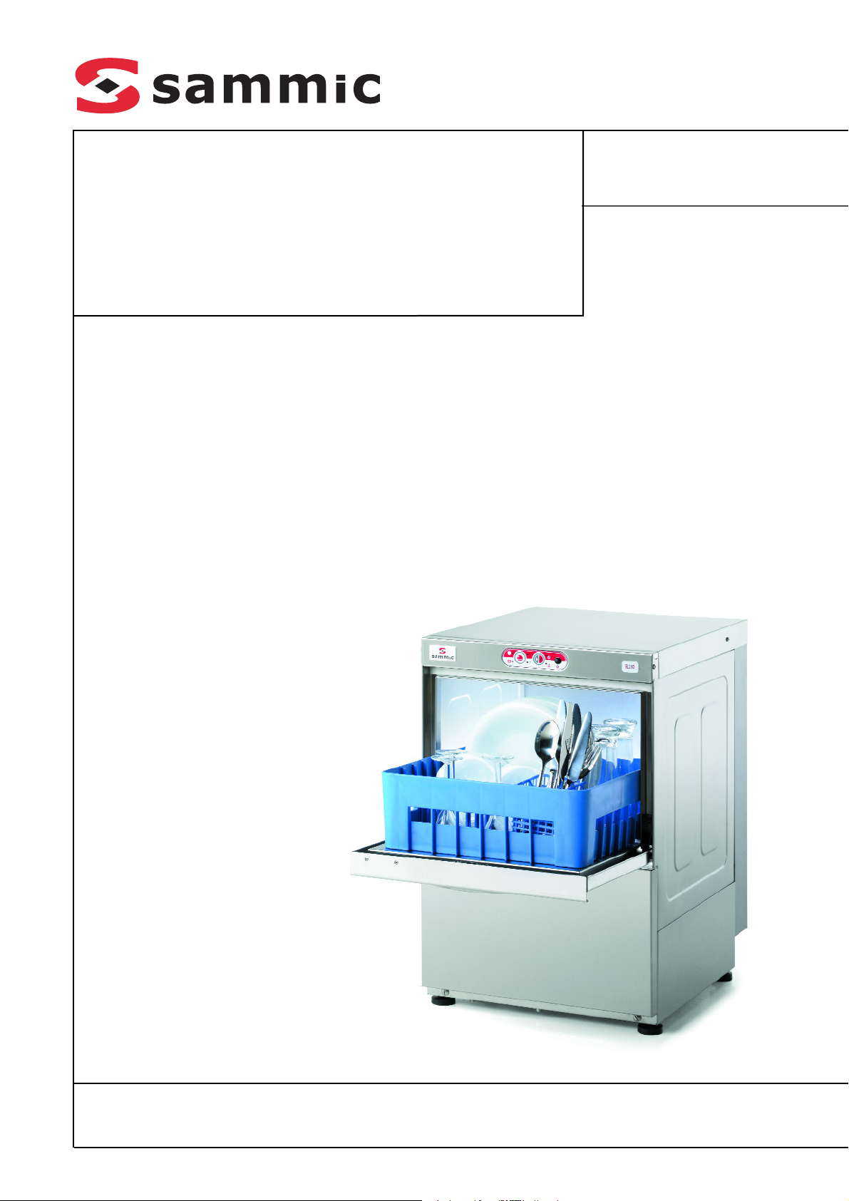
SL-19D
SL-20D
Lavavasos
Glasswashers
Gläserspülmaschinen
Lave-verres
Lavatazze
Máquinas de lavar copos
MODELOS
Este manual describe la instalación, funciona
miento y mantenimiento de los lavavasos: SL19D y SL-20 D.
La referencia del modelo y sus características se
indican en la placa de identificación colocada en
la máquina.
Estas máquinas están diseñadas y fabricadas de
acuerdo con las directivas Europeas de seguridad
89/392/CEE y 73/23/CEE.
Este aparato cumple con las normas EN55014 y
EN55104 sobre la eliminación e inmunidad de las
perturbaciones radioeléctricas.
INSTALACION
Para obtener las mejores prestaciones y una
buena conservación de la máquina, siga cuida
dosamente las instrucciones contenidas en este
manual.
Instalación de agua
Antes de proceder a la instalación de la máquina,
compruebe que:
1. La conducción de agua se encuentra a una
distancia inferior a 1,50 m del emplazamiento
previsto para la máquina.
2. La conducción de agua deberá tener en su
extremo más cercano a la máquina una llave
de corte de 3/4'' GAS a la que se conecta la
manguera de alimentación suministrada con la
máquina.
3. La presión dinámica de agua de alimentación a
la máquina no deberá ser ni inferior a 2 bar
(200kPa) ni superior a 4 bar (400kPa).
El caudal del agua de alimentación debe ser
4.
como mínimo de 20l/min.
En zonas donde la presión del agua sea mayor
5.
a la máxima indicada, es necesario instalar un
regulador de presión para situar la presión
entre 2 y 4 bar (200 y 400kPa).
6. Si la presión del agua es inferior a 2 bar
(200kPa), es necesario instalar un elevador de
presión.
7. Evitar hacer reducciones con la manguera al
hacer la instalación.
8. En los modelos con desagüe por gravedad,
conectar el tubo de desagüe que tiene un diá
-
metro exterior de 30mm, al conducto de desagüe. La altura del desagüe no deberá ser
superior a 120 mm desde la base de la máqui
-
na.
En los modelos "B", provistos de bomba de
9.
desagüe, la altura del desagüe no deberá ser
superior a 1 m desde la base de la máquina.
Es necesario nivelar la máquina para permitir
10.
un correcto vaciado, para ello se deben soltar o apretar las patas niveladoras.
Instalación con elevador de presión
por un extremo a la llave de corte y por el otro a
la manguera que se suministra con la maquina.
Instalación eléctrica
Máquinas monofásicas: 230V / 50Hz / 1f
Antes de proceder a la instalación de la maquina:
1. Comprobar que el voltaje de la red coincide
con los datos indicados en la placa de carac
-
terísticas.
2. Instalar un interruptor diferencial bipolar (2P)
con sensibilidad de 30 mA y uno de tipo magnetotérmico bipolar de 16A (2P). . La máquina
está equipada con un cable 3x2.5 mm² de
sección y 2m de longitud que debe ser conectado directamente al interruptor.
2. Es OBLIGATORIO efectuar la conexión con TIERRA. Además, la máquina está provista de un
tornillo externo para la conexión a un sistema
equipotencial de tierra.
FUNCIONAMIENTO DEL CONTROL
ELECTRÓNICO
Descripción técnica del panel de mandos: Figura
A
S
ELECCIÓN DURACIÓN DEL CICLO
ECLA
T
(2)
Mediante sucesivas pulsaciones de la tecla "2" se
selecciona la duración del ciclo de lavado entre
dos tiempos diferentes: Los pilotos indican el
ciclo seleccionado:
"c": Ciclo corto.
"d": Ciclo largo.
El tipo de ciclo adecuado depende de la suciedad
de la vajilla a lavar: a mayor suciedad conviene
elegir un ciclo más largo para un lavado intensi
-
vo.
Dibujo
RRANQUE DEL CICLO
A
(3)
La pulsación de esta tecla arranca el ciclo de
lavado iluminándose el correspondiente piloto
"a". Finalizado el lavado, automáticamente pasa
al aclarado indicado con el piloto "b". Cuando
termina el aclarado la maquina queda en reposo
y los indicadores "a" y "b" parpadeando. La aper
tura de la puerta o arranque de otro ciclo anula
este parpadeo.
Pulsando sucesivamente esta tecla pasamos de
una fase a otra del ciclo. Si está en el lavado, pul
sando la tecla, se pasa al aclarado y si esta aclarando pasamos al reposo.
Ajuste de las Temperaturas de trabajo:
Las máquinas salen de fábrica ajustadas a:
· Temperatura de Cuba: 55-60ºC
· Temperatura del Calderín: 85-90ºC
Detección de averías:
El acceso a las conexiones de la placa electróni
ca solo podrá ser realizado por personal de repa
-
ración cualificado, tras cortar la corriente eléctrica con el interruptor general de la máquina y el
interruptor automático de protección situado
en la toma exterior de alimentación de la
máquina.
La placa electrónica consta de una serie de indi
cadores luminosos que son muy útiles a la hora
de ver el funcionamiento de la maquina o detectar algún fallo. Estos indicadores se dividen en
dos grupos, indicadores de entradas y de salidas:
Leds Indicadores de entrada: Se refieren a la
información que recibe la placa electrónica (Su
posición y descripción se observa en la placa
serigrafiada y en la Figura B), son los siguientes:
Pilotos de color amarillo
· Led "PUERTA": Iluminado, la puerta esta cerra-
da.
· Led "TCALD". Iluminado, contacto del termosta-
to cerrado.
· Led "TCUBA". Iluminado, contacto del termosta-
to cerrado.
· Led "PRESOST": Iluminado, presostato está acti-
vado, la cuba está llena.
Leds Indicadores de salida: Indica el elemento
que ha sido activado por el microprocesador (Su
posición y descripción se observa en la placa
serigrafiada y en la Figura B), son los siguientes:
Pilotos de color rojo
· Led "C.CALD." rele resistencia calderín:
Iluminado, resistencia calderin activada.
· Led "C.CUBA" rele resistencia cuba: Iluminado,
resistencia cuba activada.
Led "B.LAVADO": Iluminado bomba de lavado en
·
marcha.
· Led "EV.CAL": Iluminado, electrovalvula de acla-
rado activada.
Led "EV.FRIA": Iluminado, electrovalvula de agua
·
fría o regeneración activada.
Ejemplo: si el led de la bomba de lavado está
encendido y la bomba no funciona quiere decir
que la placa da la orden de marcha correctamente, el fallo se encuentra en elementos externos a
la placa como podría ser la bomba.
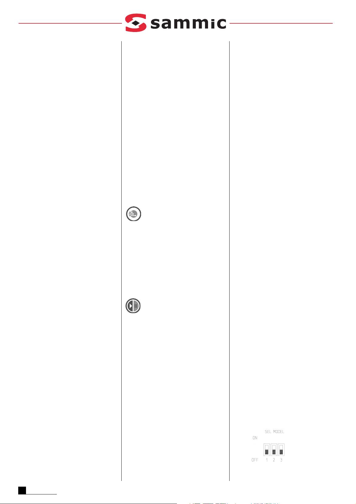
Configuración de modelos:
ELECCIÓN DEL MODELO
S
:
El modelo de máquina se elige mediante la combinación de 3 microruptores ( Fig. B- 1) de la
placa electrónica. Para ello:
1. Apagar la máquina
2. Accionar los microinterruptores (Fig. B-1)
según tabla adjunta.
3. Encender la máquina
Instalar un elevador de presión cuando la presión
de agua que va alimentar a la maquina es inferior
a 2 bar. (200kPa). El elevador de presión puede
instalarse en cualquier punto cerca del equipo,
prolongando la conducción de agua y la llave de
corte hasta el elevador. Cuidar que la llave de
corte siga estando accesible. Conectar el levador
2
ESPAÑOL
A
JUSTE DE TEMPERATURAS
· Ajuste temperatura cuba: Mediante el termosta
:
-
to de cuba.
· Ajuste temperatura calderin: Mediante el ter
-
mostato de calderin.

La tabla de modelos es la siguiente (SL-19D y SL20D):
Control de la duración del ciclo (Enclavamiento
de temperatura, Thermal Lock) según el calenta
miento del calderin:
El control electrónico dispone de la opción de
ajustar la duración del ciclo hasta que el calderín
haya alcanzado la temperatura prefijada. Es
decir, en caso de que el calderín no hubiera
alcanzado la temperatura correcta, el ciclo conti
núa hasta que se alcance la temperatura de ajuste. Esto evita que el aclarado se haga con agua
fría. Para seleccionar esta opción basta elegir el
Nº del cuadro adjunto.
FUNCIONAMIENTO
Puesta en marcha
1. Abrir la llave de paso del agua 3/4'' GAS.
2.
Conectar el interruptor magnetotérmico de
protección de la instalación.
3.
Comprobar que los filtros y el rebosadero
indicados en la figura "C" están colocados.
4. Accionar el interruptor general (Fig. A-1) para
iniciar el llenado automático de la cuba y la
conexión de las resistencias de calentamiento.
5.
Cuando la máquina haya alcanzado la temperatura de lavado (55º/60ºC), se ilumina el
piloto (Fig. A-e).
6. Ciclo de arranque:
-Colocar los objetos para lavar en la cesta.
-Cerrar la puerta.
-
Seleccionar el programa de lavado mediante
botón "selección ciclo" (Fig. A-2).
-Pulsar la tecla de arranque del ciclo (Fig. A-3). El
indicador luminoso del ciclo de lavado (Fig. A-a)
se enciende. Se realiza el ciclo de lavado completo. Si estando en el ciclo de lavado se pulsa
de nuevo la tecla de arranque (Fig. A-3), pasamos al ciclo de aclarado y si está aclarando a la
parada del ciclo.
7. Una vez acabado el ciclo completo, los dos
pilotos (Fig. A-a) y (Fig. A-b) parpadean indi
-
cando el fin del ciclo.
Dosificador de Detergente:
La maquina esta preparada para la instalación de
una bomba dosificador de detergente regulable,
cuyo numero de repuesto se indica en la lista de
repuestos. El dosificador se monta en el frente
inferior delantero según se indica en la figura del
despiece. La maquina dispone de un orificio en la
parte trasera donde se acopla el racord par la
inyección de jabón.
La bomba dosifica aproximadamente 0,7ml/s de
detergente (máximo). En el primer llenado se
inyectan aproximadamente 119ml de detergente
en 170s, obteniendo una concentración máxima
de 3 ml/l. En cada ciclo la bomba inyecta 10ml de
detergente. La dosificación se puede disminuir o
aumentar girando el tornillo de regulación que
dispone el dosificador.
Dosificador de abrillantador:
Comprobar que el deposito de abrillantador esta
lleno. Poner en macha y parar la bomba de lava
do 5 ò 6 veces mediante sucesivas pulsaciones
de la tecla "Arranque ciclo" (Fig. A-3), compro
bando que el tubo de abrillantador se llena y
entra en el calderin. La regulación del abrillanta
dor se hace mediante el tornillo de reglaje situa
do en la parte frontal inferior y según el sentido
indicado.
Para comprobar si la dosis de abrillantador es
eficaz observar los vasos al trasluz. Si hay gotas
de agua en el vidrio la dosis es insuficiente; si
aparecen estrías, la dosis es muy alta.
Desagüe de la máquina:
Abrir la puerta y extraer el rebosadero sin retirar
los filtros El agua cae por gravedad y la suciedad
queda acumulada en los filtros.
Sistema de descalcificación. Ciclo de regenera
-
ción.
Realizar la regeneración del sistema de descalcificación aproximadamente cada 30 ó 50 aclara
dos.
1. Desaguar por completo la cuba. MAQUINA
VACIA SIN REBOSADERO.
2. Con la puerta abierta, al pulsar "selección de
ciclo" (Fig. A-2) se enciende el piloto
"Regeneración" (Fig. A k). Indica que hemos
accedido al ciclo de regeneración.
3.
Cerrar la puerta y pulsar "Arranque ciclo" (Fig.
A-3) para iniciar el ciclo de regeneración.
4.
El piloto "Regeneración" (Fig. A-k) empieza a
parpadear y al cabo de 6 sg da comienzo el
ciclo de regeneración. Durante estos 6 prime
-
ros se puede para el ciclo volviendo a pulsar
"Arranque ciclo" (Fig. A-3).
5.
Este ciclo dura 23 minutos y no es posible
detenerlo. El piloto "Regeneración" (Fig. A-k)
esta encendido hasta que acaba el ciclo.
6. Cuando el piloto "Regeneración" (Fig. A-k) se
apague apagar la maquina.
Sistema de descalcificación. Reposición de sal
para la regeneración.
El acceso al recipiente para la sal de regeneración
se encuentra dentro de la cuba de lavado. Para
reponer dicha sal:
1. Desaguar por completo la cuba.
2.
Comprobar el recipiente que se encuentra
dentro de la cuba contiene sal. Añadir si es
necesario sal común hasta llenar el recipiente.
Con el recipiente lleno se pueden realizar
hasta 3 regeneraciones.
Vaciado del Calderin:
1. Vaciar la cuba
2. Cerrar el paso de agua de alimentación a la
máquina
3.
Soltando el tubo que conecta la salida de la
bomba de abrillantador con el tubo de entra
-
da al calderin queda libre este último y colocando un recipiente, sale por gravedad todo el
contenido de agua del calderin.
Limpieza de la cuba:
La limpieza de la cuba debe realizarse cada vez
que se termina una sesión de lavado al final del
día. Proceder así:
· Extraer el filtro de seguridad de la bomba de
lavado (L), fijado en bayoneta, girándolo en el
sentido contrario de las agujas del reloj.
· Al final del día conviene vaciar la máquina,
hacer un llenado y realizar un ciclo de lavado en
vacío, sin cestas, de manera que se realice una
limpieza del interior de la máquina.
· Limpiar finalmente el fondo, paredes e interior
de la cuba.
· Los brazos de lavado es preciso limpiarlos
periódicamente. Si se observan deficiencias en
el aclarado puede ser debido a la obstrucción de
los orificios. En ese caso se deben soltar y pro
-
ceder a su limpieza
·
El exterior de la máquina NO SE DEBE limpiar
con un chorro directo de agua. Emplear para su
limpieza un paño húmedo y cualquier deter
-
gente habitual.
·
NO SE DEBEN utilizar detergentes abrasivos
(aguafuerte, lejía concentrada, etc.), ni estropajos o rasquetas que contengan acero común,
pueden causar la oxidación de la máquina.
OTRAS OBSERVACIONES IMPORTANTES
· Antes de cualquier intervención para la limpieza o reparación, es obligatorio desconectar la
máquina de la red.
·
Cuando el aparato no se utilice durante un largo
período de tiempo, o durante la noche, se recomienda dejar la puerta abierta para facilitar la
ventilación y evitar malos olores.
·
En caso de avería de la bomba de desagüe:
1. Se debe vaciar la cuba mediante un recipien-
te hasta que el nivel de agua esté por debajo
del rebosadero.
2. Con el rebosadero colocado, soltar el panel
frontal inferior y cambiar la bomba (es posi
ble realizar esta operación sin mover la
máquina de su emplazamiento). Si desea
vaciar la máquina manualmente, se debe
conectar un tubo de desagüe al colector. Al
retirar el rebosadero, la cuba se vacía por
gravedad.
·
Si el cable de alimentación se deteriora y es preciso instalar uno nuevo, dicho recambio sólo
podrá ser realizado por un servicio técnico
reconocido por SAMMIC.
· Ruido aéreo: el ruido emitido por la máquina,
medido sobre una máquina tipo, es de 71dB(A)
(distancia 1m).
· Este aparato no está destinado para ser usado
por personas (incluido niños) cuyas capacidades
físicas, sensoriales o mentales estén reducidas,
o carezcan de experiencia o conocimiento,
salvo si han tenido supervisión o instrucciones
relativas al uso del aparato por una persona
responsable de su seguridad
Nº
C
ICLOS
(SG)
T
HERMAL
L
OCK
T
IPO
DE CICLO
D
ESCALCIFICADOR
M
ICRORUPTOR
1
M
ICRORUPTOR
2
M
ICRORUPTOR
3
5
120
210
OFF
OFF
ON
6
120
210
ON
OFF
ON
ESPAÑOL
3
MODELS
This manual describes the installation, operation
and maintenance of the SL-19D and SL-20 D
glasswhashers.
The model reference and its specifications are
shown on the identificacion plate located on the
machine.
These machines have been designed and manu
factured in accordance with the following
European directives for safety: 89/392/EEC and
73/23/EEC.
These appliances comply with the EN55014-1
and EN55104-2 standards for the suppression
and exemption of radio-frequency interferences.
INSTALLATION
For optimum performance and long service life of
the machine, follow the instructions contained in
this manual rigorously.
Water connection
Before proceeding with the installation of the
machine, check and make sure that:
1. The mains water connection is within 1.50m
from the foreseen location of dishwasher.
2.
At its end on the machine side, the water
supply connection is equipped with a 3/4" GAS
stopcock for the coupling of the water supply
hose supplied with the machine.
3. The dynamic pressure of the water supplied to
the machine is not less than 2 bar (200kPa)
and not greater than 4 bar (400kPa).
4. Inlet water flowrate is at least 20l/min.
5.
In places where the water pressure is higher
than the specified one, it will be necessary to
incorporate a pressure reducer to bring the
service pressure within the limits of 2 to 4 bar
(200 to 400kPa).
6. Where water pressure is less than 2 bar
(200kPa), it is necessary to install a pressure
booster pump.
7. Avoid bottlenecks with hoses when making
this installation..
8.
On models with gravity draining, connect the
drain pipe of an O.D. of 30mm to the sewage
system. The distance from the sewage system
to the machine base shall not exceed 120mm.
9.
On models "B" fitted with a drain pump, the
distance from the sewage system to the
machine base shall not exceed 1m.
10.
In order to ensure complete drainage, it is
essential that the machine is even. To level it,
undo or screw in the levelling feet.
Machine installation with a booster pump
Install a pressure booster pump when supply
water pressure is less than 2 bar (200kPa). You
can place the pressure booster pump anywhere
near the appliance, extending the water pipe and
stopcock to the booster pump. Take care that the
stopcock is still accessible. Connect one side of
the booster pump to the stopcock and the other
side to the water supply pipe to the machine.
Electric installation
Single-phase machine: 230V / 50Hz / 1ph
Before starting to install the machine:
1.
Check whether the voltage of the machine (on
its rating plate) coincides with the mains voltage.
2.
Fit a 30 mA two-pole differential switch (2P)
and a 16 A two-pole magnetic switch (2P).
The machine is equipped with a cable of a
cross section of 3x2.5 mm² and 2m in length.
This cable must be connected directly to the
switch.
3. EARTHING is OBLIGATORY. Moreover, the
machine includes an external screw for its
connection to a ground equipotential system.
OPERATION OF THE ELECTRONIC CONTRO
-
LLER
Technical description of the control panel: Figure
A
C
YCLETIMESELECTOR
(2)
By pushing key (2) repeatedly, you can select any
of two wash cycle times. Light indicators show
the selected cycle:
"c": Short Cycle.
"d": Long Cycle.
Choosing the adequate cycle depends on how
soiled crockery is. The dirtier it is, the longer the
cycle has to be for an intensive, thorough was
-
hing.
Start Cycle (3) Fig. A.
If you press this key, the wash cycle starts and
the associated LED (a) turns on. At the end of the
washing phase, the rinsing process starts auto
matically and this is shown by LED (b). Once rinsing has finished, the machine shifts to the
stand-by condition, with LEDs (a) and (b) flas
hing. Flashing stops when the door is opened or
a new cycle starts.
Press the key repeatedly to move from one phase
of the cycle to another. So, if washing is on, press
the key to shift to the rinsing process. During
rinsing, press the key to put the machine standby.
Adjustment of Working Temperatures:
Temperatures are factory-set at:
·55-60ºC for the wash tank
·85-90ºC for the boiler
T
EMPERATURESETTING
:
· Setting of wash tank temperature: by means of
the wash tank thermostat.
·
Setting of boiler temperature: by means of the
boiler thermostat.
Troubleshooting:
Only qualified technicians may work on the connections of the electronic board, after cutting out
power to the machine with the main switch and
the automatic safety circuit-breaker at the exter
-
nal feeding point to the machine.
On the electronic board, there are several light
indicators which are very useful for monitoring
the machine operation and malfunction. Those
indicators belong to either of two groups: input
LEDs or output LEDs.
Input LEDs: those associated with information
received by the electronic board. Their location
and description are indicated on the silk-screened board and on Figure B. The following are
amber LEDs:
· 'DOOR' LED: ON, when the door is closed.
·
BOILER TEMP' LED: ON, when thermostat contact makes.
·
'TUB TEMP' LED: ON, when thermostat contact
makes.
· 'PRES.SW' LED: ON, when pressure switch is on,
the tub is full.
Output LEDs: They identify the item that has
been activated by the microprocessor. Their
location and description are indicated on the
silk-screened board and on Figure B. The follo
-
wing are red LEDs:
· "C.CALD." LED (boiler resistor relay): ON, when
boiler resistor is heating water.
·
"C.CUBA" LED (wash tank resistor relay): ON,
when wash tank resistor is heating water.
·
"WASH PUMP" LED: ON, when wash pump is
working.
·
"BOILER S.V." LED: ON, when rinsing solenoid
valve is active.
· "COLD S.V." LED: ON, when cold water or regeneration solenoid valve is active.
Example: If the Washing Water Pump LED is on
and the pump does not work, this means that the
microprocessor gives the order correctly and the
fault lies in an external item such as the contactor or the pump.
Model Configuration:
S
ELECTION OF MODEL
:
To select the machine model, you have to set the
3 microswitches ( Fig. B- 1) on the electronic
board. For this purpose:
1. Power the machine down.
2.
Set the microswitches (Fig B-1) according to
the following table.
3. Power the machine up.
4
ENGLISH

Microswitch setting tabe (SL-19D and SL-20D):
Control of cycle time (Thermal Lock) as a function
of the boiler temperature:
The electronic controller features the possibility
of increasing the cycle time until the preset tem
perature is reached in the boiler. So, in the event
the temperature of the boiler were lower than the
preset value, the cycle would be extended until
the preset temperature is reached. This prevents
rinsing with cold water. In order to enable this
feature, select the appropriate digit from the
enclosed table.
OPERATION
Start-up
1.
Open the 3/4" stopcock to allow water to enter
the machine.
2. Turn on the magnetothermal switch that pro-
tects the installation.
3. Check that the filters and the drain plug are in
place, as Figure "C" shows.
4. Turn the main switch (Fig. A-1) to the ON
position for the automatic filling of the wash
tank and the connection of the heater ele
-
ments.
5.
The light indicator (Fig.A-e) turns on when the
washing temperature (55º/ 60ºC) has been
reached.
6. Start Cycle:
-Place the objects to be washed in a basket
(rack).
-Close the door.
-
Select the washing programme by pressing
key "select cycle" (Fig. A-2).
-
Press the Start Cycle key (Fig. A-3). The washing phase indicator light (Fig. A-a) turns on.
The machine completes the entire washing
cycle. If you press the Start Cycle key (Fig. A-
3) again during the washing phase, the programme immediately shifts to the rinsing pro
cess. Pressing the said key during the rinsing
phase causes the machine to stop.
7.
When the complete cycle has finished, the two
indicators (Fig. A-a) and (Fig. A-b) flash.
Detergent dispenser
The glasswasher is prepared for its fitting with an
adjustable detergent dispenser, the part number
of which appears on the spare parts list. This dis
-
penser has to be installed in the machine base, at
the front, as shown on the exploded view. At the
rear of the wash tank, there is an opening where
to insert the detergent injection nozzle.
The dispenser delivers about 0.7ml/s of detergent (maximum). At the first filling of the tank,
feeding of detergent is roughly 119ml in 170s,
resulting in a maximum concentration of 3ml/l.
At each cycle, the dispenser delivers 10ml of
detergent. It is possible to reduce or increase the
injected quantity by turning the adjusting screw
on the dispenser.
Rinsing aid dispenser
Verify that the rinsing aid reservoir is full. Start
and stop the washing water pump 5 or 6 times by
pressing the "Start Cycle" (Fig. A-3) and check
whether the tube fills up with rinsing aid and
goes in the boiler. Setting the dispenser is done
by turning an adjusting screw on the front lower
panel in the direction shown on the panel graph.
In order to determine whether the amount of rinsing aid is adequate, look at the glasses against
the light. If there are water droplets on the glass,
the amount of rinsing aid is insufficient; if streaks develop, the quantity of rinsing aid is too
much.
Machine Draining
Open the door and take out the drain plug, leaving the filters in place. Water will fall by gravity,
dirt accumulating in the filters.
Water Softener. Regeneration Cycle.
Regnerate the descaler every 30 or 50 rinsing
cycles approximately.
1. Drain the wash tank completely. MACHINE
EMPTY WITHOUT DRAIN PLUG.
2.
With the door open, press "Select Cycle" (Fig.
A-2), the "Regeneration" LED (Fig. A k) turns
on, meaning the machine is ready for the
regeneration cycle.
3. Close the door and press "Start cycle" (Fig. A-
3) to start the regeneration cycle.
4. The "Regeneration" LED (Fig. A-k) starts flashing and the regeneration cycle starts after 6
seconds. During those 6 seconds, you can
stop the cycle by pressing "Start cycle" (Fig. A-
3) again.
5.
This cycle lasts 23 minutes and cannot be
stopped. The "Regeneration" LED (Fig. A-k)
remains ON until the cycle finishes.
6. When the "Regeneration" LED (Fig. A-k) turns
off, switch the machine off.
Water Softener. Refilling regenerating salt.
The regenerating salt container is accessible
through the inside of the wash tank. To refill the
salt container:
1. Drain the wash tank completely.
2. Check to see if there is any salt left in the container. Add kitchen salt as and when necessary
to fill the container. A full container permits
three regeneration cycles.
Boiler Draining
1. Drain the wash tank.
2. Close the water inlet.
3.
Remove the tube coming from the rinsing aid
pump from the inlet connector to the boiler
and place a container under the boiler. All
water flows out of the boiler by gravity.
Tank cleaning
The tank should be cleaned after every washing
process, at the end of the day, proceeding as
follows:
·
Remove the bayonnet safety filter from the
wash pump (L) by twisting it counterclockwise.
· At the end of the day, it is advisable to drain the
dishwasher, fill it with water and have a wash
cycle done on no load, without any racks, in
order to clean the interior of the machine.
· Finally, clean the bottom, walls and interior of
the tank.
·
Spray arms must be cleaned periodically. If rin
sing is deficient, the cause may be an obstruction of the jets. In this event, dismount the arms
and clean the jets.
·
The outside of the machine MUST NOT BE was
hed under a direct water jet; instead you can
use a wet cloth and any ordinary detergent.
· DO NOT USE any abrasive detergent (etchant,
concentrated lye, etc.) nor any scourer or scraper containing normal steel that will cause rust
to develop on the machine.
OTHER IMPORTANT REMARKS
· Before cleaning, servicing or repairing the
machine, it is necessary to unplug it from the
mains.
· When the appliance is going to be inactive for a
long period of time or at night, the door should
be kept open for aeration and avoiding nasty
smell.
· In case of a drain pump failure:
1. Drain the wash tank into a container until
the water level drops below the drain plug.
2. With the drain plug in place, remove the
front bottom panel and change the pump
(this can be done without moving the
machine). In order to drain the machine
manually, connect a drain hose to the
collector. On pulling out the drain plug,
water flows out of the tank by gravity.
·
In the event the power supply cable should get
damaged and have to be replaced, the repair
may only be done by a SAMMIC approved assistance service.
· Airborne noise: the emission noise level measured on a typical machine is 71 dB(A) at a distan
-
ce of 1m.
· This machine is not designed to be used by
individuals (including children) with reduced
physical, sensorial or mental facilities, or who
lack the relevant experience or knowledge,
unless they are supervised by or have received instruction on how to use the apparatus
from a person responsible for their safety.
Nº
C
YCLE
T
IME
(
SEC
)
T
HERMALLOCK
CYCLE TYPE
W
ATER SOFTENER
M
ICROSWITCH
1
MICROSWITCH 2
M
ICROSWITCH
3
5
120
210
OFF
OFF
ON
6
120
210
ON
OFF
ON
ENGLISH
5
 Loading...