

Sam4s NR-500R, NR-500 Service Manual

ELECTRONIC CASH REGISTER
CONTENTS
NR-500 Series
ELECTRONIC CASH REGISTER
Manual
1. Precaution Statements
2. Product Specifications
3. Installation and Operation
4. Disassembly and Assembly
5. Maintenance and Adjustment
6. Exploded Views and Parts List
7. PCB Layout and Parts List
8. Troubleshooting
9. Block diagram
10. Wiring Diagram
11. Schematic Diagrams
SERVICE

About this Manual
This service manual describes how to
perform hardware service maintenance for
the SAM4S NR-500 Series
Electronic Cash
Register.
Notes
Notes may appear anywhere in the
manual. They describe additional
information about the item.
Precaution symbols
. Indicates a Safety Precaution that
applies to this part component.
. Indicates the part or component is an
electro-statically sensitive device
. Use
caution when handling these parts.

ȱ
ȱ
ȱ
ȱ
ȱ
ȱ
ȱ
ȱ
ȱ
ȱ
ȱ
ȱ
ȱ
ȱ
ȱ
ȱ
ȱ
ȱ
ȱ
ȱ
ȱ
ȱ
ȱ
ȱ
Copyright
གྷȱ2017ȱbyȱShinȱHeungȱPrecision.ȱ
ȱȱȱȱAllȱrightȱreserved.ȱ
Thisȱ manualȱ mayȱ not,ȱ inȱ wholeȱ orȱ inȱ part,ȱ
beȱ copied,ȱ photocopied,ȱ reproduced,ȱ
translatedȱorȱ convertedȱ toȱ anyȱ electronicȱ orȱ
machineȱȱreadableȱ fromȱ withoutȱ priorȱ
writtenȱ permissionȱ of
ȱ
Shinȱ Heungȱ
Precisionȱ.ȱ
ServiceȱManualȱ6thȱEdition.ȱ
Oct.ȱ2017ȱ
V1.6ȱ
ȱ
PrintedȱinȱKOREAȱ
SAM4S NR-500 SERIES
ȱ
ȱ
ȱ
ȱ

Overview of thi s E CR
This serv ice manual pr ovi des the technical information for many individual c o mponent systems, c ircuits and
giv es an anal y si s of the operations performed by the cir c uits. If you need more t ec hnical i nform ation, pl ease
contact our service branc h or R& D c enter. Schematics and specificat ions provide the needed informat ion for
the accurate t r oubleshooting.
All i nform ation in t his manual is subject to change without prior notice. Therefore, you must check the
correspondence of your manual with your machine. No par t of this manual may be copied or repr oduc ed in any
form or by any means, without t he pr ior written c onsent of Shin Heung Precision .
Note: Before using t his Electronic Cash Register (ECR) for the first t ime, leave it powered on in the REG mode
for at least twenty-f our hour s. This allows the MS Lithium battery, which mai ntains the memory of the
ECR while the power is of f, to c har ge c ompletely.
“Proper disposal of batter ies is required. Refer to your local codes f or disposal requir ements.”
Note: The socket outlet shall be installed near the equipment and shall be easily accessible.

SAM4S NR-500 SERIES 1-1
1 Precaution Statements
Follow these safety, servicing and ESD precautions to prevent damage and to protect against potential hazards such as
electrical shock.
1-1 Safety Precautions
1. Be sure that all buil t-in protective devi ces are
replaced. Restore any missing protective shields.
2. When reinstalling the chassis and its as semblies, be
sure to r e s tor e all protect ive devices , incl uding
nonmetallic control knobs and compartment covers.
3. Make sure there are n o ca binet openings through
which people - particularly children - might insert
fingers and contact dangerous voltages.
Such open ings include excess ively wide cabinet
ventilation slots and improperly fitted covers and
drawers.
4. Design Alteration Warning:
Never al ter or add to the mechan ical or electrical
design of the ECR. Unauthorized alterations might
creat e a sa fety hazard. Also, any desi g n ch anges or
additions will void the manufacturer’s warranty.
5. Components, parts and wiring that appear to have
overheated or that are otherwise damaged should be
replaced with parts that meet the original
specifications. Always determine the cause of
damag e or over- hea ting, and correct an y potentia l
hazards.
6. Observe the original lead dress, especially near the
following areas : sharp edges, and especially the AC
and high voltage supplies.
Always inspec t for pin ched, out-of-pl ace, or frayed
wiring. Do not change the spacing between components and the prin ted circui t board. Check the A C
power cord for damage. Make sure that leads and
components do not touch thermally hot parts.
7. Product Safety Notice:
Some electrical and mechanical parts have special
safety-related c ha racteristicswhich might not be
obvious from visual inspection.
These sa fety featu res and th e protection they give
might be lost if the replacement component differs
from the origin al - even if the repla cement is rat ed
for higher voltage, wattage, etc.
Components that are critical for safety are indicated
in the circuit di agram by shading, (
) or ( ).
Use replacement components that have the same
ratings, especially for flame resistance and dielectric
strength specifications. A replacement part that
does not have the same safety characteristics as the
original might create shock, fire or other hazards.
CAUTION
Danger of explosion if battery is incorrectly replaced.
Replace only with the same or equivalent type
recommended by the manufacturer.
Dispose used batteries according to the manufacturer’s
instructions.
ATTENTION
ll y a danger d’explosion s’il y a remplacement incorrect
de la batterie.
Remplacer uniquement avec une batterie du même type
ou d’un type équivalent recommandé par le constructeur.
Mettre au rebut les batteries usagées conformément aux
inst ruc tion s du fabrica nt.

1 Precaution Statements
1-2 SAM4S NR-500 SERIES
1-2 Servicing Precautions
WA RNING: First read the-Safety Precautions-section of this manual. If some unforeseen circumstance creates a conflict
between the servicing and safety precautions, always follow the safety precautions.
WA RNING: An electrolytic capacitor installed with the wrong polarity might explode.
1. Servicing precautions are printed on the cabinet.
Follow them.
2. Always unplug the units AC power cord from the AC
power source before attempting to:
(a) Remove or reinstall any component or assembly
(b) Disconnect an electrical plug or connector
(c) Connect a test component in parallel with an
electrolytic capacitor
3. Some components are raised above the printed circuit
board for safety. An insulation tube or tape is
sometimes used. The internal wiring is sometimes
clamped to prevent contact with thermally hot
components. Reinstall all such elements to their
original position.
4. After servicing, always check that the screws,
components and wiring have been correctly
reinstalled. Make sure that the portion around the
serviced part has not been damaged.
5. Check the insulation between the blades of the AC
plug and accessible conductive parts
(examples : metal panels and input terminals).
6. Insulation Checking Procedure:
Disconnect the p ower cord from the AC sour ce an d
turn the power s witch ON. C onnect an ins u lation
resistance meter (500V) to the blades of AC plug.
The insulation resistance between each blade of the
AC plug and accessible conductive parts (see above)
should be greater than 1 megaohm.
7. Never defeat any of the B+ voltage interlocks.
Do not apply AC power to the unit (or any of its
assemblies) unless all solid-state heat sinks are
correctly installed.
8. Always connect an instrument’s ground lead to the
instrument chassis ground before connecting the
positive lead ; always remove the instrument’s ground
lead last.
1-3 Precautions for Electrostatic Sensitive Devices (ESDs)
1. Some semiconductor (solid state) devices are easily
damaged by static electricity. Such components are
called Electrostatic Sensitive Devices (ESDs);
examples include integrated circuits and some fieldeffect transistors. The following techniques will reduce
the occurrence of component damage caused by static
electricity.
2. Immediately before handling any semiconductor
components or assemblies, drain the electrostatic
charge from your body by touching a known earth
ground. Alternatively, wear a discharging wrist-strap
device. (Be sure to remove it prior to applying power
- this is an electr ic shock precauti on.)
3. After removing an ESD-equipped assembly, place it
on a conductive surface such as aluminum foil to
prevent accumulation of electrostatic charge.
4. Do not use freon-propelled chemicals. These can
generate electrical charges that damage ESDs.
5. Use only a grounded-tip soldering iron when
soldering or unsoldering ESDs.
6. Use only an anti-static solder removal device. Many
solder removal devices are not rated as anti-static;
these can accumulate sufficient electrical charge to
damage ESDs.
7. Do not remove a replacement ESD from its protective
package until you are ready to install it. Most
replacement ESDs are packaged with leads that are
electrically shorted together by conductive foam,
aluminum foil or other conductive materials.
8. Immediately before removing the protective material
from the leads of a replacement ESD, touch the
protective material to the chassis or circuit assembly
into which the device will be installed.
9. Minimize body motions when handling unpackaged
replacemen t ESDs. Moti ons such as brushin g cloth es
together, or lifting a foot from a carpeted floor can
generate enough static electricity to damage an ESD.

SAM4S NR-500 SERIES 2-1
2 Product Specifications
Specifications are correct at the time of printing. Product specifications are subject to change without notice.
See below for product specifications.
2-1 General Specification
Item Description Remark
Processor
x RENESAS CPU R5F5631ECDFB (RX-631 , 32-Bit)
Memory
x RAM(DATA)
SRAM (R1LV0408DSP-5SI) : 4Mbits
SRAM (R1LV0408DSP-5SI) : 4Mbits (Option)
x ROM(PGM)
CPU ON CHIP FLASH ROM : 16Mbits
x FISCAL ROM
OTP-ROM(AT27LV020A) : 2Mbits (Default)
OTP-ROM(AT27LV040A) : 4Mbits (Option)
Selectable
Selectable
Backup Battery
x Type : MS Lithium, 3.0V 11mAh
x Part Name : MS920S
x Charging Time : 24 Hours
x Life : 3 Years
Data Storage
x 180 Days
When battery is Full charged
Interface Serial
(RS-232C)
x Flow Control :
ᐭG DTR / DSR : H/W Flow Control
ᐮG XON / XOFF : S/W Flow Control
x Baud Rate : 1200 / 2400 / 4800 / 9600 / 19200 / 115200 Bps
x Connector : Serial#1 / DSUB9F (Female)
Serial#2 / RJ45
Serial#3 / RJ45
x Voltage Supply : +5V/150mA supplies at #9-Pin of DSUB9 Connector,
#1-pin RJ45 Connector.
USB
x USB A-Type (Default)
Transfer Type : BULK
Speed : 12 Mbps (USB 2.0 Full-Speed)
Power : Self-Powered
ETHERNET x 10/100 base-T (Option)
GPRS x Built-in type (Option)
SD CARD
x 1-Slot [ MICRO SD CARD (Internal) ] (Option)
x 1-Slot [ SD CARD (external) ] (Option)
Printer
x Model : LTP01-245-11
x Print Speed : 70mm/sec, 15 Lines/sec
x Type : Thermal Dot Line Printing
x Resolution : W 8 dots/mm x H 16 dots/mm
x Paper End Sensor (Reflecting Photo Sensor)
Detail Spec refer to Next
Page
Display
x Operator : 192 x 64 dot, Graphic LCD, Blue backlight(White LED)
x Customer : 16set x 2 line + Icon , Negative , Blue backlight(White LED)
Key Board
x Raised Key : 48 key (with CAP), NR-500R
x Flat Key : 90 key (with water proof), NR-500
Drawer x 24V / 15 ȍ Solenoid (Recommend)
Power Consumption x Regularity : Approx. 10W
Power Source x AC/DC Adapter : 9V / 2.5A
Environment Condition
x Temperature : 0 ~ 35
x humidity : 30% ~ 80% RH
Dimensions(mm)
x 400(W) x 450(D) x 266(H)
with Drawer
Weight x 11.5 Kg (Set Only)
Table2-1 General Specification

2 Product Specifications
2-2 SAM4S NR-500 SERIES
2-2 Appearance
2-2 A. Appearance Dimensions (mm)
Figure2-1 Dimensions
2-2 B. Location Feature
Figure2-2 Location Feature
£G Printer Cover
¤G Key Board
¥G Drawer
¦G Customer Display
§G Operator Display
¨G Mode Ke y
©G RS-232 Serial I/F Connector
NR-500R (Raised Keyboar d)
NR-500
(Flat K ey boar d)

2 Product Specifications
SAM4S NR-500 SERIES 2-3
2-3 Thermal Printer Specification
2-3 A. Printer Specification (58mm*1station or 2station)
Item Description Remark
Model
x LTP01-245-11
Print Method
x Thermal Dot Line Printing
Printing Format
T otal Dots Per Line
x 384 Dots
Dot Pitch
x Vertical : 0.125 mm
x Horizontal : 0.125 mm
Printing Speed
x 70mm/sec, 15 L ines/sec
Printing Direction
x Unidirectional Friction Feed
Paper Feeding
Feeding Method
x Friction Feed
Minimum Feed Pitch
x 0.0625 mm
Maximum Feeding Speed
x 75 mm/sec (At 8.5V of Motor Voltage )
Power Supply Volt
Power Voltage
x 4.2~9.5V (Recommend)
TPH / Motor
Circuit Input Voltage
x 3.3V
Head Control / Sensor
Printer Head
Heat Element Density
x 8 Dots/mm (0.125mm/Dot)
(1step 0.0625mm)
Total Head Elements
x 384 Dots/Dot Line
Available Printing Width
x 48 mm (384 Dots)
Line Feed Moto r
x 1-2 Phase Bi-Polar Stepping Motor
Sensor
Head Temperature
x Thermistor
Out-of-paper Detection
x Reflection type p hoto interrupter
Platen Position Detection
x Mechanical Switch
(Option)
Reliability Life
x 50km or more
Dimension (mm)
x 70.3 (W) ×32.7 (D) ×15.3 (H)
Weight
x Approx. 44 g
Table2-2 Thermal Printer Specificat ion

2 Product Specifications
2-4 SAM4S NR-500 SERIES
2-3 B. Paper Specification
Item Description Remark
Pape r T y pe
x Single-ply Thermal Paper Roll
Pape r Size
x 57.5 mm±0.5 (Width) × Ø 70 mm or less
Specified Paper
x Original Paper No : HPK-110 (Hansol paper XT)
Table2-3 Paper Specif ications
Note: The following paper can be used instead of the specified paper above.
TF50KS-E2D: Nippon paper industries Co.,Ltd.
PD 150R, PD160R-N : O ji paper Co.,Ltd.
F380 : Kansaki specialty papers, Inc. (US A )
2-3 C. Character Specification.
Item Description Remark
Chara cter Structure
x 12(W) × 24(H) Font
Character Size
x 1.25 mm(W) ×3.0 mm(H)
Column Pitch
x 1.5 mm
Line Pitch
x 4mm (Including 8-dot line spacing)
x 3.75 mm (Including 6-dot line spacing)
SPEED 40mm/s
SPEED 30mm/s
Number of Column
x 32(12×24 Dots/Character)
Table2-4 Character Specification
2-4 Power Specification
Item Description Remark
Input Volta ge
x AC 100-240V, 50-60Hz (Min : 90V, Max : 265V)
Power Consumpti on
x Regularity : Approx. 10W
Output Voltage
x DC 9V / 2.5A
Powe r Adap ter Output
Table2-5 Power Specif ication

2 Product Specifications
SAM4S NR-500 SERIES 2-5
2-5 Interface Specification
2-5 A. RS-232C Serial Interface
2-5 A-(a) Specification
Item Description Remark
Data Transmission
x Serial
Synchronization
x Asynchronous
Hand Shaking
(Flow Control)
x H/W : DTR / DSR
x S/W : XON / XOFF
XON : ASC Code 11h
XOFF : ASC Code 13h
Signal Level
x Logic”1” (MARK) : -3V ~ -15V
x Logic”0” (SPACE) : +3V ~ +15V
Baud Rate
x 1200 / 2400 / 4800 / 9600 / 115200 bps
Data Word Length
x 8 Bit
Parity
x None
Connector
x DSUB9F (Female) / RJ45
Voltage Supply
x +5V/150mA is supplied at #9-Pin of D-SUB Connector,
#1-Pin of RJ45 Connector.
For Bar Code Reader
or other devices
Table2-11 RS-232C Specification
2-5 A-(b) Cable Connection
7
8
4
5
1
2
)RSD( 6
)C.N( 7
)DXT( 3
)RTD( 4
)G.F(
)C.N( 1
ELAMEF
6
3
)DXR( 2
)G.S( 5
)C.N( 8
C P
NIP9 EDIS
trohS)niP 8,6(&
)niP 7,
4(
)RSD( 6
)C.N( 7
)DX
T( 3
)RTD( 4
ELAM
)G.F(
)C.N( 1
ELAM
D'B NO RCE
ELAMEF
ROTCENNOC
)DXR( 2
)G.S( 5
)C.N( 8
RCE
NIP9 EDIS
)C.P ot R.C.E( tuoyaL elbaC
ecafretnI laireS C232-SR
C P
ROTCENNOC
Figure2-4 RS232C Cable Connection (9Pin to 9Pin)
)RSD( 6
)STR( 7
)RSD( 6
)G.S( 7
)DXT( 3
)RTD( 4
)DXT( 3
)STC( 4
)G.F()G.F(
)C.N( 1)C.N( 1
ELAM
ELAM
ELAMEF
)DXR( 2
)G.S( 5
)STC( 8
)DXR( 2
)STR( 5
trohS)niP 8,6(&)niP 7,4(
6
7
3
4
1
D'B NO RCE
RCE
NIP9 EDIS
)RTD( 02
2
5
8
RETNIRP/TSOH
NIP52 EDIS
)P52 TSOH ot R.C.E( tuoyaL elbaC
ecafretnI laireS C232-SR
NIP52 TSOH
ROTCENNOC
ELAMEF
ROTCEN
NOC
Figure2-5 RS232C Cable Connection (9Pin to 25Pin)

2 Product Specifications
2-6 SAM4S NR-500 SERIES
2-5 A-(c) RS-232C I/F Cable (DSUB 9 PIN MALE TYPE)
Figure2-6 RS-232C Cable
2-5 A-(d) Signal Description (DSUB Connector)
Pin No. Signal Name Signal Direction Function
BODY Frame GND - Frame Ground
2 RXD Input Receive Data
3 TXD Output Transmit Data
4 DTR Output
This Signal indicates whether the ECR(NR-500) is busy. (H/W flow control)
ᐭG MARK(Logic1) : The ECR is busy
ᐮG SPACE(Logic0) : The ECR is not busy
The host transmits a data to the ECR, after confirming th i s signal.
When XON/XOFF flow control is selected, the host does not check this signal.
5 Signal GND - Signal Ground
6 DSR Input
This signal indicates whether the host computer or receipt printer can receive data. (H/W
flow control)
ᐭG MARK(Logic1) : The host can receive a data.
ᐮG SPACE(Logic0) : The host can not receive a data
The ECR transmits a data to the host or receipt printer, after confirming this signal.
When XON/XOFF flow control i s sel ected, the prin ter does not check this signal.
9 VCC Output VCC(+5V/150mA) is supplied at #9-Pin of DSUB9 Connector.*CAUTION*
Table2-12 RS-232C S ignal Description
2-5 A-(e) Signal Description (RJ-45 Connector)
Pin No. Signal Name Signal Direction Function
1 VCC Output VCC(+5V/150mA) is supplied at #1-Pin of RJ-45 Connector. *CAUTION*
2 DSR Input
This signal indicates whether the host computer or receipt printer can receive data. (H/W
flow control)
ᐭGMARK(Logic1) : The host can receive a data.
ᐮGSPACE(Logi c0) : The host can not receive a data
The ECR transmits a data to the host or receipt printer, after confirming this signal.
3 TXD Output Transmit Data
4 RXD Input Receive Data
7 Signal GND - Signal Ground
8 DTR Output
This Signal indica tes whether the ECR(NR-500) is busy. (H/W flow control)
ᐭGMARK(Logic1) : The ECR is busy
ᐮGSPACE(Log ic0) : The ECR is not bu sy
The host transmits a data to the ECR, after confirming this signal.
Table2-13 RS-232C Signal Description

2 Product Specifications
SAM4S NR-500 SERIES 2-7
2-5 A-(f) RS-232C I/F Cable (RJ-45 CONNECTOR TYPE)
5(RTS)
6(CTS)
3(TXD)
7(S.GND)
2(DSR)
7(RTS)
8(CTS)
5(S.GND)
3(TXD)
4(DTR)
8(DTR)
4(RXD)
6(DSR)
2(RXD)
Figure2-7 RS232C Cable Connection (RJ- 45 to DSUB 9Pin)
5(RTS)
7(S.GND)
8(DTR)
3(TXD)
4(RXD)
4(RTS)
7(S.GND)
6(DSR)
2(TXD)
3(RXD)
6(CTS)
2(DSR)
5(CTS)
20(DTR)
Figure2-8 RS232C Cable Connection (RJ- 45 to DSUB 25Pin)
Caution: T he V CC is supplied for the barcode or device power source. The Suppl y Cur r ent 150mA is
total value including Serial #1 and Serial #2 P ower Consumption. If the Total Power Consumption
of the attached dev ices is exceeded t he specifi c ation(150mA ) , the system stops the VCC of
D-SUB & RJ45 Connec tor
Caution: If the device with 5V/150mA is connected t o S er ial #1, t he V CC of Seri al #2 can not use.
If the devi c e with 100mA is connect ed to Serial #1, Other device with 50mA can be connected
to Serial #2 Port.
15m
15m

2 Product Specifications
2-8 SAM4S NR-500 SERIES
2-5A-(g) H/W Flow Control Timing
When DT R/DSR f low control is select , bef ore transmi tt ing a data, the E CR checks whether the host is BUSY
or not.
If the host is BUSY, ECR does not transmit a data to the host. If the host is not BUSY, ECR t r ansmits a data to
the Host. The host i s t he same. Refer to the Interface Part of Chapter 7(Special Circuit Diagram s).
2-5 A-(h) S/W Flow Control Timing
When XON/ XOFF flow control is selected, the ECR transmits XON(ASCII 11h) or XOFF(ACSII 13h) signal
through the Serial Data Line. I f the ECR i s busy, the printer transmits XOFF(ASCII 13h) to host t hrough the
Serial Data Line. Then the host recognizes that the ECR i s busy. So, the host does not transmit a data to the
ECR. If the ECR is released from busy, the ECR transmits XON(ASCII 11h) to host through the Serial Data
Line. Then the host recognizes that the ECR is not busy. And the host transmits a data to the ECR.

2 Product Specifications
SAM4S NR-500 SERIES 2-9
2-5 Interface Specification
2-5 B. USB Interface
2-5 B-(a) USB Specification
Item Description Remark
Transfer T y pe Ɣ BULK
Data Signal
Ɣ Bi-Direction, Half-Duplex
Ɣ Differential Signal Pair (D+ / D-)
Data Format
Ɣ NRZI Format
Ɣ Zero Bit Stuffing after 6 Ones
Transceiver
Ɣ Differential Common Mode Range : 0.8 ~ 2.5[V]
Ɣ Differential Receive Sensitivity : 200[mV]
Ɣ Single End Receive Threshold : 0.8 ~ 2.5[V]
Speed Ɣ 12 Mbps (USB 2.0 Full-Speed)
Power Ɣ Supply Self Power
Cable & Connector
Ɣ Cable : 5m / 2m
Ɣ Connector : A-type
Support Spec Ɣ USB 2.0 Full-Speed
2-5 B-(b) USB Signal Description
Pin No Signal Name Color Function
SHELL Shield Drain Wire Frame GND
1 VBUS Red 2 D- White Differential Data Line
3 D+ Green Differential Data Line
4 GND Black Signal GND
2-5 B-(c) USB Interface Cable
NR-500 SIDE
USB A TYPE USB A TYPE
( USB I/F CABLE )
USB B TYPE USB A TYPE
OTHER
DEVICE
SIDE

2 Product Specifications
2-10 SAM4S NR-500 SERIES
2-5 Interface Specification
2-5 C. ETHERNET Interface (Option)
2-5 C-(a) ETHERNET Signal Specification
Pin No Signal Name Signal Direction Function
1 ENET TX+ OUT Ethernet Tra nsmit Data Line (+)
2 ENET TX- OUT Ethernet Transmit Data Line(-)
3 ENET RX+ IN Ethernet Receive Data Line(+)
4N.C -5N.C -6 ENET RX- IN Ethernet Receive Data Line(-)
7N.C -8N.C --
2-5 C-(b) ETHERNET Interface Cable
NR-500 SIDE
1
8
1
8
MAX 100M
5(N.C)
7(N.C)
8(N.C)
4(N.C)
5(N.C)
6(ENET RX-)
7(N.C)
1(ENET TX+)
2(ENET TX-)
3(ENET RX+)
6(ENET RX-)
1(ENET TX+)
2(ENET TX-)
3(ENET RX+)
4(N.C)
8(N.C)
( NR-500 to HOST IRC I/F CABLE )
7(N.C)
8(N.C)
6(ENET RX-)
7(N.C)
2(ENET TX-)
3(ENET RX+)
4(N.C)
6(ENET RX-)
4(N.C)
2(ENET TX-)
3(ENET RX+)
5(N.C)
1(ENET TX+)
8(N.C)
5(N.C)
1(ENET TX+)
( NR-500 to HUB IRC I/F CABLE )
OTHER
DEVICE
SIDE

2 Product Specifications
SAM4S NR-500 SERIES 2-11
2-6 Drawer Kick-Out Specification
2-6 A. Drawer Signal Description
Pin No Signal Name Direction Function
1 S.G - Signal GND
2 DRA WER OUT Drawer Kick-Out Driver Sign al
3 DRA_COMP IN Drawer Open / Close Signal
4 +24V - Supply DC +24V
5--N.C
6 F.G - Frame GND
6
1
( DRAWER CONNECTOR )
5HFRPPHQG9ȍ6 ROHQRLG

2 Product Specifications
2-12 SAM4S NR-500 SERIES
MEMO

SAM4S NR-500 SERIES 3-1
3 Installation and Operation
3-1 System Configuration
Figure 3-1 System Configuration
3 Installation and Operation
3-2 SAM4S NR-500 SERIES
3-2 Installation
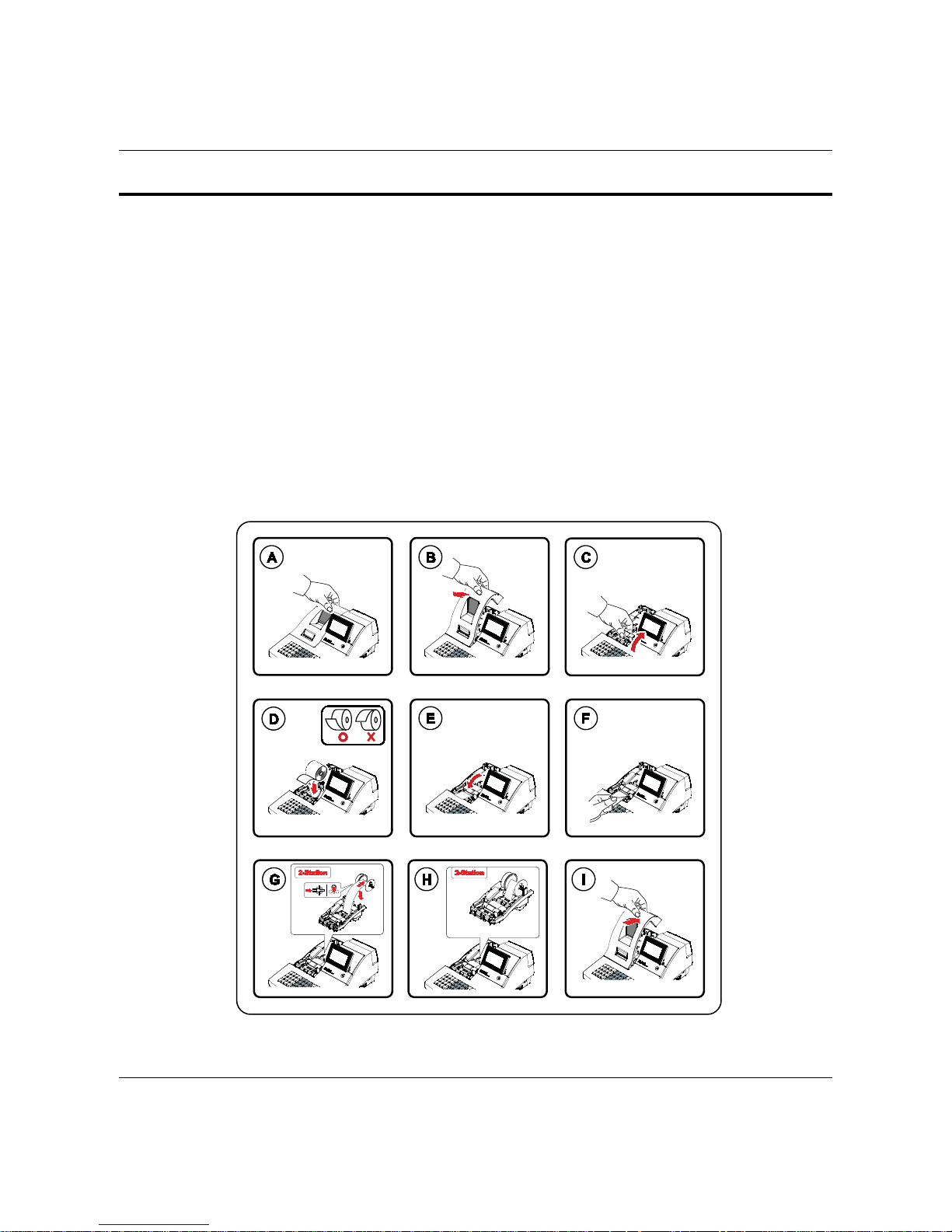
3-2 A. Paper Roll Installation
1. Remove the printer cover. (Fig 3-2 (A),(B))
2. Open the housi ng c over. (F ig 3-2 (C) )
3. Insert t he paper roll as shown. (Fig 3- 2 (D))
4. Be sure to note the correct direction that the paper comes off the rol l. (F ig 3-2 (D) )
5. Pull out a smal l amount of paper as shown. Then close the housing cov er. (Fig 3-2 (E))
6. Passing the l eading edge of t he paper thr ough the cutter slot. Tear off the ex c ess paper.(Fig 3-2(F) )
7. In case of 2station feed the leading edge of t he paper in about 150m m and f ol d the t i p i n 20m m . I nsert the
leading edge of the paper into the sl ot on the Spool W inding. (Fig 3-2(G) )
8. Insert t he Spool W inding i n 2~3 tur ns and place it on the Paper Suppl y. If it loosen, tur n to ti ghten i t. (Fi g
3-2(H))
9. Replace the printer c over. (F ig 3-2 (I))
Figure 3-2 Paper Installation

3 Installation and Operation
SAM4S NR-500 SERIES 3-3
3-2 B. RS-232C Serial Cable Installation
1.Connect the RS-232C serial cable to the RS-232C seri al port on the right side of E CR.
2.Secure the serial cable with screws.
3.Connect or the other end of the RS-232C serial Cabl e to your host computer.
Figure 3-3 Cable I nstallation
3-2 C. Options
No. Item Description Remark
1 Water Proof Raised Keyboard (Option)
2 Memory SRAM 4MBITs (4MBITs * 1) (On Main PBA) Factory option
3 Pulley Winding Spool motor & Pulley Factory option
Table 3-1 Option
3-2 D. Supplies
No. Item Description Remark
1 Paper Roll
1EA(1-station)
2 EA (2-sta ti on)
2 Mode Key VD, REG, Z, P, C
3 User Manu al 1 EA
4 Spool 1 EA (2-station only)
Table 3-2 Supplies

3 Installation and Operation
3-4 SAM4S NR-500 SERIES
3-3 Operation
Note: Before using t his Electronic Cash Register ( E CR) for the first t ime, leave it powered ON in t he REG mode
for a at l east 24 hours. Thi s allows the MS-Lithium Rechargeable battery, which maintains t he ECR’s
memor y while the power is OFF, to full y c har ge.
3-3 A. Mode Switch
The position of the Mode Key determ ines the action of t he E CR. The modes are as shown in Table 3-3.
Figure3-4 Mode Switch Table3-3 Mode Switch Function
The mode switch can be used to access the fol lowing key lock posi tions.
KEY Accessible Position Remark
VOID VOID, OFF, Register(REG), Manager(X)
REG OFF, Reg ister(REG)
Z VOID, OFF, Register(REG), Manager(X), Clear Totals(Z)
P VOID, OFF, Register(REG), Manager(X), Clear Totals(Z), Program(PGM)
C
VOID, OFF, Register(REG), Manager(X), Clear Totals(Z), Program(PGM), Service
Mode(S)
ALL POSITIONS
Table3-4 Key Function
Note : The Key can be removed from the key lock in the OFF or REG position.
Mode Function
VOID Use to void (correct) items outside of a sale.
OFF The Register is inoperable.
REG Use for norm al registrations.
X Use to read registe r reports an d perform o ther manager functions.
Z Use to read register reports and reset totals to zero.
PGM Use to program the register.
S
Use for H/W tests and special setting. The S position is hidden
position reserved for dealer access.

3 Installation and Operation
SAM4S NR-500 SERIES 3-5

3 Installation and Operation
3-6 SAM4S NR-500 SERIES
3-3 B. Key Board Matrix
1 32
4 65
7 98
DETL
FEED
ERROR
CORR
LEVEL2
PRICE
INQ
VOID
X/TIME
RETURN
NOSALE
0
.
00
CLEAR
LEVEL1
CANCEL
%1
5
8
10
11
9
6
12
7
1
4
2
3
RA
(PAGE
˨
)
CHARGE1
(˦)
CHECK
(
˨
)
PO
(PAGE
˦
)
CASH
CONV1
SUB
TOTAL
RCPT
FEED
SERVICE
RCPT
ON/OFF
CHECK#
PLU
Figure3-5 Raised Keyboard (NR- 510R / NR-520R)
27 45 39 33 3 21 15 9 51
#NOSALE
57
26 44 38 32 2 20 14 8 50
RCPT
ON/OFF
56
28 46 40 34 4 22 16 10 52
52 43 37 31 1 19 13 7 49
RCPT
FEED
55
VOID
58
29 47 41 35 5 23 17 11 53
RETURN
59
30 48 42 36 6 24 18 12 54
CANCEL
60
87
PLU
CLEAR
RA
(PAGE
˦
)
DETL
FEED
ERROR
CORR
54
21
000
CHARGE1
(˦)
9
%1X/TIME
CLERK
PO
(PAGE
˨
)
CHECK
(˨)
6
SBTL
3
CASH
.
Figure3-6 Flat Keyboard (NR-510 / NR- 520)

3 Installation and Operation
SAM4S NR-500 SERIES 3-7
3-3 C. Initial Clear
The init ial clear f unction allows you to exi t any register activ ity and retur n to a beginni ng or cleared state.
Any transaction that is in progress will be exited and totals for t hat transaction will not be updated.
1.Move to the PROGRAM MODE.
2.Turn the power switch loc ated on the right si de of the register to the OFF position.
3.Pr ess and hold t he k ey posi tion where the SUBTOTAL key is located on the default keyboard layout.
8
5
11
10
12
7
9
6
4
1
3
2
RA
CHARGE1
(˦)
CHECK
(
˨
)
PO
CASH
CONV1
SUB
TOTAL
51
VOID
57
50
#NOSALE
56
52
49
FEED
55
RETURN
58
53
ERROR
CORR
59
54
CANCEL
60
87
PLU
CLEAR
RA1
RECEIPT
ON/OFF
54
21
000
CHARGE1
(˦)
9
%1X/TIME
CLERKPO1
CHECK
(˨)
6
SBTL
3
CASH
.
Figure3-7 I nitial Clear Key for NR-510R/NR-520R F igure3-8 Ini tial Cl ear K ey for NR-510/NR- 520
4.Whi le continuing to hold the SUBTOTAL k ey, turn the power switch to the ON positi on. When the “INITIAL
CLEAR” message displays release the SUBTOTAL key.
5.Pr ess the CASH key.
6. Press the CASH key. The message "INITIAL CLEAR OK” prints when the initial clear is complete. To
resume operati ons, y ou will need to sign on a clerk.
ARE YOU SURE?
Y=CASH N=CLEAR
INITIAL CLEAR
ENTER CASH KEY

3 Installation and Operation
3-8 SAM4S NR-500 SERIES
3-3 D. All Clear
This step insures that the cash register i s clear ed of any t otals or progr am m ing. Af ter t hi s procedure, t he cash
register is ready for programming and oper ation.
WARNING: This is a one time procedu re. Do not repeat this p rocedure after the cash register is
programmed, it causes all programs an d totals to b e erased and to b e default.
Note : You need “ C Key ” to execute a SERVICE M ODE.
1.Move to the SERVICE MODE.
2.Turn the power switch loc ated on the right si de of the register to the OFF position.
3.Pr ess and hold t he key position where the A(CHECK) key i s l oc ated on the default keyboard layout.
4. Continue to hold the appropriate key while turning the power switch to the ON position. The message
“RAM ALL CLEAR" displays.
5.Pr ess the upper left k ey of t he keyboard, then the l ower left key, then the upper r ight key, and f i nally press
the lower right k ey.
3
A
4
1
2
Figure3-9 <Raised Keyboard – NR-510R / NR-520R>
1
2
3
A
4
.
Figure3-10 <Flat Keyboard – NR-510 / NR-520>

3 Installation and Operation
SAM4S NR-500 SERIES 3-9
6.T he S E RVICE M ODE m enu displays. The RAM Clear pr oc edur e is complete and the receipt prints.
Figure3-11 A ll Clear K ey S equenc e & P r int Sheet
2014/05/12 MON 09:00
* * * * * * * * * * * * * * * *
MEMORYALL C LEAR OK
* * * * * * * * * * * * * * * *
MEMORY ALLOC A TION
RAM 8Mbits OK
RAM 1 OK
RAM 2 OK
TTL AVAIL : 851968 Bytes
TTL USED : 327850 Bytes
================
VERSION INFORMAT ION
= = = = = = = = = = = = = = = =
VERSION : NR-500 : STD 00.001
CHECKSUM : 084F
BOOT/APP : BFBC/4893
PLUs USED : 60/2000
KEYBOARD : 90 KEYs
03.27 2014
CLERK 00 No.000001 00000

3 Installation and Operation
3-10 SAM4S NR-500 SERIES
3-3 E. Self Test
Before the test. You will find ‘SELF TEST’ menu.
1. Move to the SERVICE MODE.
2. Press the ‘1’ to select ‘SELF TEST’.
3-3 E-(a) Test Printer
1. From the SELF TE S T menu, Pr ess ‘2’ to select PRINTER.
2. From the PRINTER menu, Press ‘1’ to select PRINT T EST.
3. After printing, The drawer is opened. Then the printer test i s finished.
4. Press the ‘CLEAR’ key to return to S E LF TEST menu.
3-3 E-(b) Test Display
1. From the SELF TEST m enu, Press ‘3’to select DISPLAY.
2. From the DISPLAY menu, Press ‘1’ to select LCD TEST.
3. Press the ‘CASH’ key 2 times to finish LCD TEST.
4. Press the ‘CLEAR’ key to ret ur n to SELF TEST menu.
3-3 E-(c) Test Key Board
1. From the SELF TEST m enu, Press ‘4’to select KEYBOARD.
2. From the KEYBOARD menu, Press ‘1’ to select KEYBOARD TEST.
3. Press any key you want on the key board.
4. The key name of pressed key will be showed on the LCD.
5. Press the ‘CLEAR’ key to return to SE LF TEST menu.
3-3 E-(d) Test Mode Switch
1. From the SELF TEST m enu, Press ‘4’to select KEYBOARD.
2. From the KEYBOARD menu, Press ‘2’ to select MODE KEY TEST.
3. Turn the mode switch to any posit ion.
4. The corresponding Mode name will be showed on the LCD.
5. Press the ‘CLEAR’ key to return to SE LF TEST menu.
3-3 E-(e) Test SERIAL1 (COM1)
1. From the SELF TEST menu, Pr ess ‘5’ to select INTERFACE.
2. Install the serial loop back test jig. (S hor t “pin 2 , 3” , ” pin 4 , 6” ) of DSUB connector.
3. From the INTERFACE menu, Press ‘1’ to select SERIAL 1.
4. If error occ ur s, the message “ ** NG ** “ i s di spl ay ed on LCD and the Buzzer beep.
5. Press the ‘CLEAR’ key to return to SE LF TEST menu.
3-3 E-(f) Test SERIAL2 (COM2)
1. From the SELF TEST menu, Pr ess ‘5’ to select INTERFACE.
2. Install the serial loop back test j ig. (Short “ pin 3 , 4” , ” pin 2 , 8” ) of RJ-45 connector.
3. From the INTERFACE menu, Press ‘2’ to select SERIAL 2.
4. If error occ ur s, the message “ ** NG ** ” i s di spl ay ed on LCD and the Buzzer beep.
5. Press the ‘CLEAR’key to return to SELF TEST menu.
SELF TEST
1. BATCH TEST
2. PRINTER
3. DISPLAY
4.KEYBOARD
5.INTERFACE
6.RTC
Figure3-11 SELF TEST MENU

3 Installation and Operation
SAM4S NR-500 SERIES 3-11
3-3 E-(g) Test SERIAL3 (COM3)
1. From the SELF TEST menu, Pr ess ‘5’ to select INTERFACE.
2. Install the serial loop back test j ig. (Short “ pin 3 , 4” , ” pin 2 , 8” ) of RJ - 45 connector.
3. From the INTERFACE menu, Press ‘3’ to select S E RIAL 3.
4. If error occ ur s, the message “ ** NG ** ” is displayed on LCD and the Buzzer beep.
5. Press the ‘CLEAR’ key to return to SE LF TEST menu.
3-3 E-(h) USB HOST TEST
1. From the SELF TEST menu, Pr ess ‘5’ to select INTERFACE.
2. Put the USB Memory Stick to the USB Host port.
3. From the INTERFACE menu, Press ‘3’ to select USB HOST.
4. If USB i s OK , “ ** OK ** “ message will be displayed.
5. Press the ‘CLEAR’key to return to SELF TEST menu.
Note : When the ports is unconnected with the cable , the Error occur.
3-3 E-(i) EXTERNAL SD TEST
1. From the SELF TEST menu, Pr ess ‘5’ to select INTERFACE.
2. Put the External SD card.
3. From the INTERFACE menu, Press ‘4’ to select EXTERNAL SD.
4. If EXTERNAL SD card is OK, “ ** OK ** “ message will be displayed.
5. Press the ‘CLEAR’ key to retur n to SELF TEST m enu.
3-3 E-(j) MICRO SD TEST
1. From the SELF TEST menu, Pr ess the ‘5’ to select INTERFACE.
2. Put the MICRO SD card.
3. From the INTERFACE menu, Press ‘5’ to selec t MICRO SD.
4. If M ICRO SD card i s OK , “ ** OK ** “ message will be displayed.
5. Press the ‘CLEAR’ key to return to S E LF TEST menu.

3 Installation and Operation
3-12 SAM4S NR-500 SERIES
3-3 F. Flash ROM Updated by SD
The NR-500 Series Flash ROM program is contained in a binary file. This file contains both the Boot
program area and t he Appli c ation program ar ea.
1. Copy binary file to the root of the SD card. : SD:/update/
2. Insert the SD card int o the register. (The S D slot is l ocated inside the printer compartment . Remov e
the security screw and open the flap securi ng the SD slot. Insert the SD card unti l you hear a click sound
and the SD card is l oc k ed in.)
Boot Area Update
3. At the NR-500 Series, move to the SERVICE MODE.
4. Press the ȡ key and theȣ key to select menu and press the CASH key to confirm. Select the
7.PROGRAM BACKUP menu.
5. Select the 1.SD menu.
6. Select the 6.BOOT UP SD menu.
7. After a short pause, the register will display confirmation of the successful download with the message
“DOWNLOAD 100 % FINISHED! !.
8. Turn the ECR power switch OFF/O N and proceed direc tly to t he next step: Application Update.
ProgramArea Update
9. Set the SERVICE MODE.
10. Press the upper right key and the lower right key. A rapid beep-beep- beep sound will be heard. Release
the upper right k ey and the lower right k ey.
11. Press the ȡ key and theȣ key to select m enu and press the CASH key to confirm. Select the 2.SD
CARD menu.
12. The display will flash (Current program is being erased), after a few seconds, the display will continue to
flash, but at a slower rate. T his continues for about 1-m inute while the new program is being l oaded.
When the load is complete, a rapid beep-beep-beep sound will be heard again the display will stop
flashing and display a blue color to c onfirm update com pletion.
13. Power the register OFF. The FLASH RO M update is complete.
14. Remove the SD card from t he r egister.
15. Perform a memory all clear on the ECR. The ECR is now ready to program or to load a prev iously
saved end-user program.
3-3 G. Flash ROM Updated by PC
Update Files
To complet e the fir mware update, you will be supplied with the following files:
x DownLoad.exe (The update ut ility program)
x Binary file
PC Connection Cable
YOU MUST USE Port #1. Use the following cable:
x P ar t # 522120 (Register DB-9MF COM 1 to PC DB- 9F)
Boot Area Update
1. Connect the Serial Cable From ECR to PC.
2. At the register, move to t he SERVICE MODE.
 Loading...