

Page 1
SAGEM
MF 3725
User Manual
S
Page 2

WELCOME
You have just acquired a new generation communications terminal from SAGEM and we congratulate
you on your choice. This multi-function terminal will meet all your professional requirements.
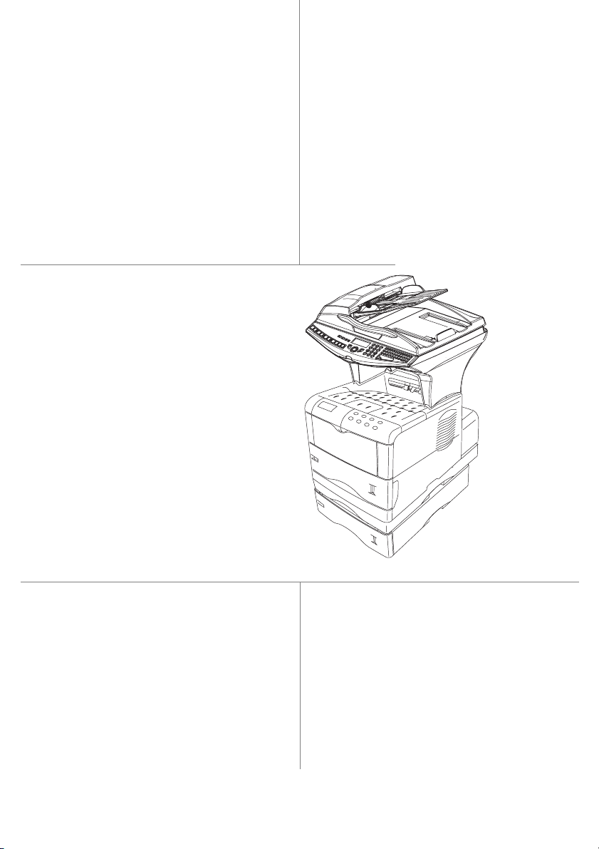
This User's Manual present the model in the range:
Model Equipement
• Duplex unit scanner colour
• 28 ppm Black & White laser printer
MF 3725
It combines power, user-friendliness and simplicity thanks to its navigator, its multitask access and its
direct access directory.
Denpending on model, you can also print to PCL® 6 and KPDL/SGScript 3 formats (emulation of
Postscript® level 3 language).
We strongly recommend that you take the time to read this manual so that you can get the most out of
your terminal's many features. Please read the safety instructions carefully (see the Safety chapter on
page 8-1).
• Front/back module
• Connection Kit PC
• LAN 10/100 Base T
List of accessories
The following additional accessories are proposed for the Fax Laser range:
• Directory card.
• 500-page paper tray.
• Companion Suite Pro PC Kit.
1
Consumables
To refer to the last page of this user manual for the references.
1. The list of accessories is subject to change without prior notice.
Page 3
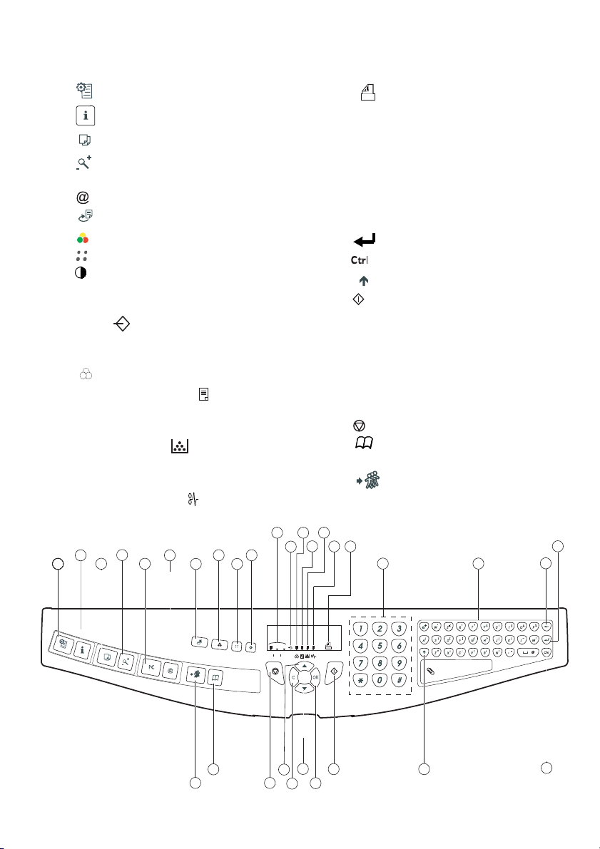
Scanner console
Fine
Sfine
Photo
1. Key :
2. Key :
3. Key :
4. Key :
5. Key
6. Key :
7. Key :
8. Key :
9. Key :
10. Key :
11.
Scan resolution (Fine (Fin), SFine (Super Fin),
Photo)
stops current printing.
help in terminal use.
local photocopy.
reduce or enlarge.
PC
: scan to PC / scan to FTP / scan to Disk
scan to e-mail (sending of Internet fax).
double sided printing
selection of colour mode
scan resolution
contrast setting
.
.
.
.
12. Icon "Ligne" :
* On : communication in progress.
* Flashing : communication setting up.
13. Icon :
14.
Recto/Verso print indicated
color mode selected
.
:
* On : duplex mode activated.
* Out : printing mode deactivated.
15. Indicator reserve "Toner" :
On : end of toner
Flashing : near the end of toner
16.
Indicator printer paper jam
,
.
.
17. Icon
fax reception icon reception
:
* On : reception possible.
* Flashing : non-printed document(s) in memory
or being received.
* Out : reception impossible.
18.
Digital keyboard.
19.
Alphabetical keyboard
Í
:
20. Key
deletes the character to the left of the
.
cursor
21. Key :
22. Key :
23. Key
24. Key :
25. Key
26. Key :
downwards
27. Key
input or line feed
access to special characters
:
Shift.
send fax
.
OK
:
validates displayed selection
access to menu and browsing in menus
.
.
.
.
C
:
return to previous menu and correction of
text
28. Key :
29. Key :
30. Key :
31. Key :
browsing in menus upwards
stops current operation
access to directory and quick dial
.
numbers
multiple contact sending (fax,
.
.
e-mail).
1
PRINT
11
13
15
14
4
2
3
COPY
COPY
5
6
SCAN
8
9
7
30
31
12
10
Fine
Sfine
Photo
28
29
16
17
18
26
24
25
27
23
19
21
20
22
Page 4
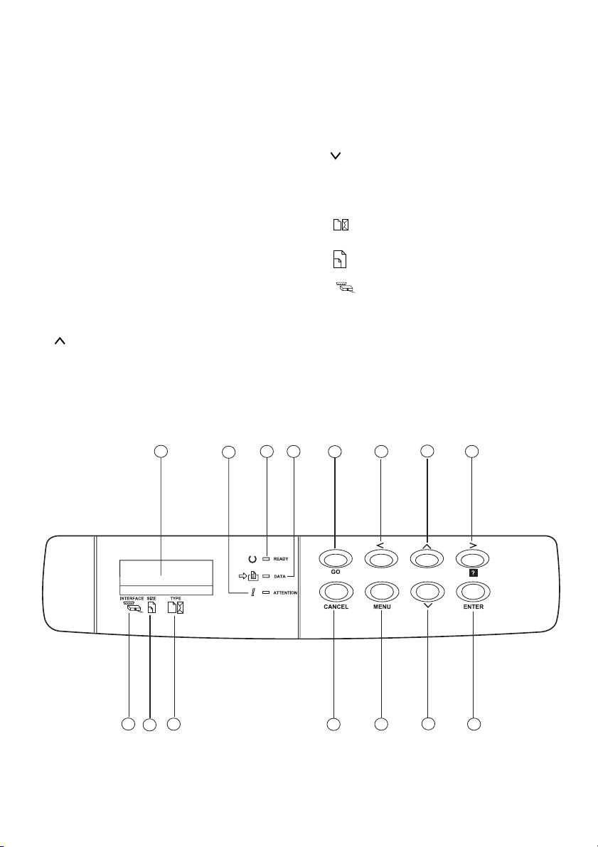
Print console
1. The console's LCD screen.
WARNING
2.
indicator:
On: A problem or error (e.g. a paper jam) has occurred.
Blinking: The printer requires maintenance or is
warming up.
3.
READY
indicator:
On: The printer is ready. It prints out any data it receives.
Blinking: An error has occurred.
Off: The printer is idle. The data has been received but
not printed out (see GO key).
DATA
4.
indicator:
On: The data has been processed or stored on the
memory card,
Blinking: Data transfer in progress.
5.
GO
key: Used to take the printer into or out of idle
mode.
6. < key: Used to navigate the submenus and make certain
settings.
7. key: Used to navigate the menus and to increase
numerical values.
1
3 4
2
8. > key: Used to navigate the submenus, make certain
settings and display help messages when certain errors
occur.
ENTER
9.
key: Confirms the numerical values and other
selections.
10. key: Used to navigate the menus and to devease
numerical values.
MENU
11.
12.
key: Used to access or exit the printer's menu.
CANCEL
key: Used to cancel a print job.
TYPE
13. indicator: Shows the paper type used in the tray.
SIZE
14. indicator: Shows the paper size used in the tray.
INTERFACE
15. indicator: Shows the interface being used (PAR,
USB, OPT and --).
5
6
7
8
15
13
14
12
11
10
9
Page 5

Contents
CONTENTS
1INSTALLATION 1-1
Installing your terminal 1-1
Installation requirements 1-1
Unpacking the components 1-4
Unpacking the additional paper tray (depending on option) 1-4
Unpacking the front/back module 1-5
Unpacking the scanner 1-6
Unpacking the printer 1-7
Description 1-8
Installing the terminal 1-9
Installing the removable components 1-24
Installing the scanner document feeder 1-24
Adjusting the original document output tray 1-25
Loading paper 1-25
Loading the multipurpose tray 1-28
Installing Consumables 1-30
Wall connections 1-33
Lan connections 1-33
Power line connection and switch on 1-33
Configuring the printer driver 1-33
Getting startedDirectoryMaintenanceSafety ContentsInstallationPrint function
Setting your
machine
2GETTING STARTED 2-1
Navigation methods 2-1
Presentation 2-1
Access to functions 2-3
Guide to function list 2-5
Print console navigation basics 2-8
Navigating the menus 2-8
Access to functions 2-9
Guide to functions 2-10
3SETTING YOUR MACHINE 3-1
Main settings 3-1
Before transmission 3-2
Before reception 3-3
Technical parameters 3-5
Local Area Network settings 3-6
Local network settings 3-6
Print function settings 3-8
Remote configuration 3-10
Fax Server (depending on option) 3-10
Message service and the Internet 3-12
Initialisation parameters 3-12
Settings 3-14
I
Operation
Page 6

Network Connection 3-17
Deactivating the Internet function 3-18
4DIRECTORY 4-1
Creating subscribers record 4-2
Adding a record 4-2
Creating subscribers lists 4-4
Adding a list 4-4
Adding or deleting a number from the list 4-5
Consulting a record or a list 4-5
Modifying a record or a list 4-6
Deleting a record or a list 4-6
Printing the directory 4-6
Importing a directory 4-6
The file structure 4-7
Procedure 4-7
Exporting a directory 4-8
LDAP server 4-8
Configuration 4-9
Accessing server contacts 4-9
Adding a server contact to the local directory 4-9
5OPERATION 5-1
Sending 5-1
Document depositing 5-1
Choosing the resolution/contrast 5-2
Dialling 5-3
Transmitting Over the Fax Server (depending on option) 5-5
Transmission over the Internet 5-5
Transmission waiting queue 5-9
Cancelling a transmission in progress 5-10
Reception 5-10
Copying 5-10
Local copy 5-11
Specific copy settings 5-13
Other functions 5-15
Logs 5-15
Printing the functions list 5-15
Printing the machine settings 5-16
Counters 5-16
Lock 5-16
Scan to PC (depends on model) 5-18
Contents
6PRINT FUNCTION 6-1
Using the console 6-1
The console 6-1
Printing test pages 6-4
II
Page 7

Contents
Paper size and type settings 6-5
Pagination 6-11
Interface 6-16
Configuring the printer 6-17
7MAINTENANCE 7-1
Maintenance 7-1
General 7-1
Replacing the consumables (toner and drum) 7-2
Cleaning 7-10
Servicing 7-11
Scanner calibration 7-11
Incidents 7-11
Printer incidents 7-12
Scanner incidents 7-15
Miscellaneous incidents 7-17
Storage 7-17
Packing and transporting the unit 7-17
Specifications 7-20
8SAFETY 8-1
Getting startedDirectoryMaintenanceSafety ContentsInstallationPrint function
Setting your
machine
III
Operation
Page 8

Contents
The mark attests that the products comply with the essential requirements of Directive R&TTE 1999/05/EC.
For user safety, in accordance with Directives 73/23/EC. For electromagnetic interference, in accordance with Directive
89/336/EC.
The manufacturer declares that the products are manufactured in accordance with ANNEX II of Directive R&TTE 1999/
5/EC.
IV
Page 9
1INSTALLATION
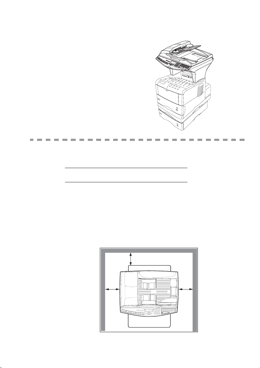
20 cm (40 cm with front/back module)
30 cm
30 cm
INSTALLING YOUR TERMINAL
INSTALLATION REQUIREMENTS
A proper location helps to ensure that your printer provides you with the long service life for which
it is designed. Double-check to make sure that the location you select has the following
characteristics.
• Choose a location that is well ventilated.
• Make sure you do not obstruct the ventilation grilles located on the left and right-hand sides of
the unit and at the rear of the Front/Back module. If there is a wall nearby when you install the
unit, make sure you install the terminal at the distances shown in the illustration below in order
to make it easier to open the various covers.
20 cm (40 cm with front/back module)
30 cm
1-1
30 cm
Page 10

• Make sure there is no chance of ammonia or other organic gasses being generated in the area.
• The grounded power outlet (refer to the safety instructions in the Safety section) you plan to connect to for power should be nearby and not obstructed.
• Make sure that the printer is not exposed to direct sunlight.
• Avoid areas in the direct airflow of air conditioners, heaters, or ventilators and areas subject to
temperature and humidity extremes.
• Choose a sturdy, level surface where the printer will not be exposed to strong vibration.
• Keep the printer away from any objects that might block its heat vents.
• Do not locate the printer near curtains or other combustible objects.
• Choose an area where there is no possibility of the printer being splashed with water or other
liquids.
• Make sure that the surrounding area is clean, dry, and free of dust.
Operational precautions
Note the following important precautions whenever using the printer.
Operating Environment
The following describes the operating environment required when using the printer:
•Temperature:
10°C to 35°C (50°F to 95°F) with fluctuation of 10°C (18°F) per hour.
• Humidity:
20% to 80% (no condensation) with fluctuation of 20% per hour.
Terminal
The following describes precautions for using the terminal.
• Never switch the power to the terminal off and never open the covers while the unit is printing.
• Never turn the terminal off or open any of its covers during a print operation.
• Never place flammable gasses, liquids or objects that generate magnetic forces near the terminal.
• When unplugging the power cord, always grasp the plug and never pull on the cord. A damaged
cord creates the danger of fire or electrical shock.
• Never touch the power cord when your hands are wet. Doing so creates the danger of electrical
shock.
• Always unplug the power cord before moving the terminal. Failure to do so can damage the
power cord, creating the danger of fire or electrical shock.
• Always unplug the power cord if you do not plan to use the terminal for a long time.
• Never try to remove any secured panel or cover. The terminal contains high-voltage circuit which
creates the danger of electrical shock when exposed.
• Make sure that the power to the printer is switched off before connecting or disconnecting an
interface lead to the printer (use a shielded interface lead).
• Never try to modify the terminal. Doing so creates the danger of fire or electrical shock.
• Never place any heavy objects on the power cord, pull on it or bend it. Doing so creates the danger of fire or electrical shock.
• Always make sure the terminal is not placed on the electrical cord or the communications cables
of any other electrical equipment. Also make sure that cords and cables do not get into the terminal’s mechanism. Any of these conditions create the danger of malfunction and fire.
Installation
1-2
Page 11

Installation
• Always take care that paper clips, staples, or other small pieces of metal do not get into the
terminal through its vents or other openings. Such objects create the danger of fire or electrical shock.
• Do not allow water or other liquids to spill on or near the terminal. Fire or electrical shock
can occur should water or liquid come into contact with the terminal.
• Should liquid or any piece of metal accidently get inside the printer, immediately turn it off,
unplug the power cord, and contact your dealer. Failure to take this immediate action creates
the danger of fire or electrical shock.
• Whenever the terminal emits unusually high amounts of heat, smoke, an unusual odor, or
noise, immediately turn it off, unplug it, and contact your dealer. Failure to take this immediate action creates the danger of fire or electrical shock.
• Avoid using the terminal during an "electrical storm" as this may involve a risk of electric
shock caused by the lightning.
• Paper for printer: do not use paper previously printed by your terminal or any other
printer: the ink or toner deposited on that paper might damage the printing system of
your terminal.
Caution - Be sure to locate the terminal in a well-ventilated location. A minimal amount of
ozone is generated during normal operation of this terminal. Because of this, an unpleasant odor
may result when the printer is used for extensive printing in a poorly ventilated area. For a
comfortable, healthy, and safe operation, be sure to locate the terminal in a well-ventilated area.
Getting startedDirectoryMaintenanceSafety ContentsInstallationPrint function
Setting your
machine
1-3
Operation
Page 12
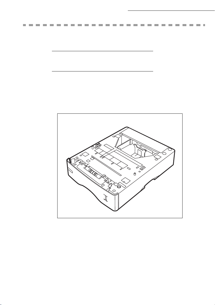
UNPACKING THE COMPONENTS
UNPACKING THE ADDITIONAL PAPER TRAY
(DEPENDING ON OPTION)
Take the additional tray out of its box.
Remove the protective side sections in the box.
Remove the plastic bag from the additional tray.
Installation
To install the additional tray please see the paragraph on Installing the terminal, page 1-9.
1-4
Page 13
Installation
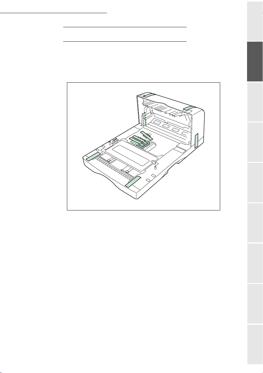
UNPACKING THE FRONT/BACK MODULE
Remove the front/back module from its box.
Remove the protective side sections.
Remove the plastic bag from the front/back module.
Getting startedDirectoryMaintenanceSafety ContentsInstallationPrint function
Setting your
machine
To install the front/back module, please see the paragraph on Installing the front/back
module on top of the additional trays (depending on model or option), page 1-9.
1-5
Operation
Page 14
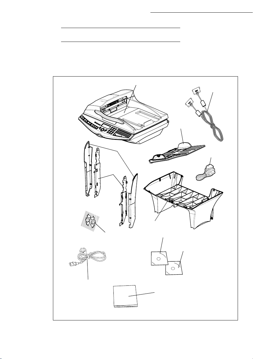
UNPACKING THE SCANNER
Take the scanner module and its accessories out of the box.
Remove the plastic bag from the scanner.
Check that you have all the components listed below.
Scanner
Installation
Centronics lead
Document
feeder
Mains power cord
(model depending
on country)
Cable holder
Feet
Interface
Cable fasteners
Mains extension
lead
Interface
User guide / Printing kit CD-ROM
Companion Suite Pro CD-ROM
(depending on model)
Installation guide
1-6
Page 15
Installation
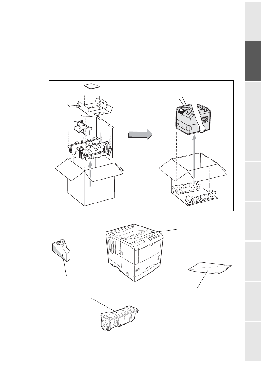
UNPACKING THE PRINTER
Take the printer and its accessories out of the box.
Remove the plastic bag from the printer.
Check that you have all the components illustrated below.
Getting startedDirectoryMaintenanceSafety ContentsInstallationPrint function
Setting your
machine
Waster Toner Box
Toner drum/cartridge
1-7
Printer
A plastic sachet used
to store the developer
(see packing procedure)
Operation
Page 16
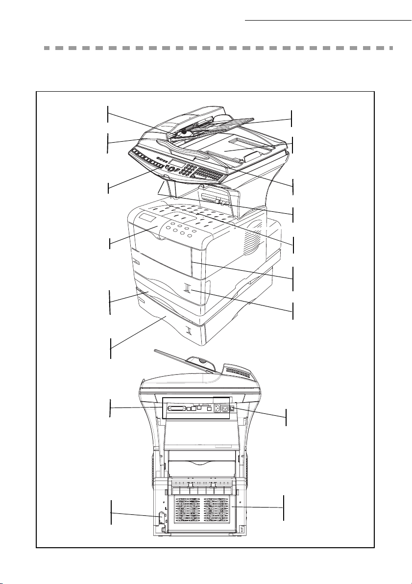
DESCRIPTION
Installation
Adjustable
paper guide
Scroll scanner
(ADF)
Scanner console
Print console
Rear front/back
module cover
Addional paper
tray (optional)
Document feed
tray for scanning
Original document
output stacker
Access handle
Flatbed scanner
Chip card reader
Printer
output stacker
Manual paper
feed tray
Printer paper feed tray
Mains connection
Mains / LAN/ USB/
lead outlets
On/Off
button
Front/back module
rear cover
1-8
Page 17
Installation
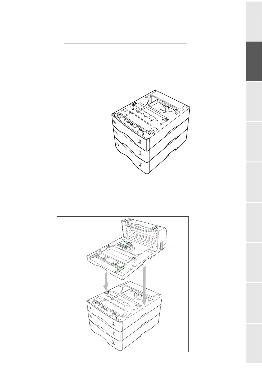
INSTALLING THE TERMINAL
Installing the additional paper tray
You can install up to 3 additional paper trays.
Note: stacking paper feeders. (When installing multiple paper feeders).
Getting startedDirectoryMaintenanceSafety ContentsInstallationPrint function
Setting your
machine
Installing the front/back module on top of the additional trays (depending on model or option)
Install the front/back module on top of the additional tray (optional).
1-9
Operation
Page 18
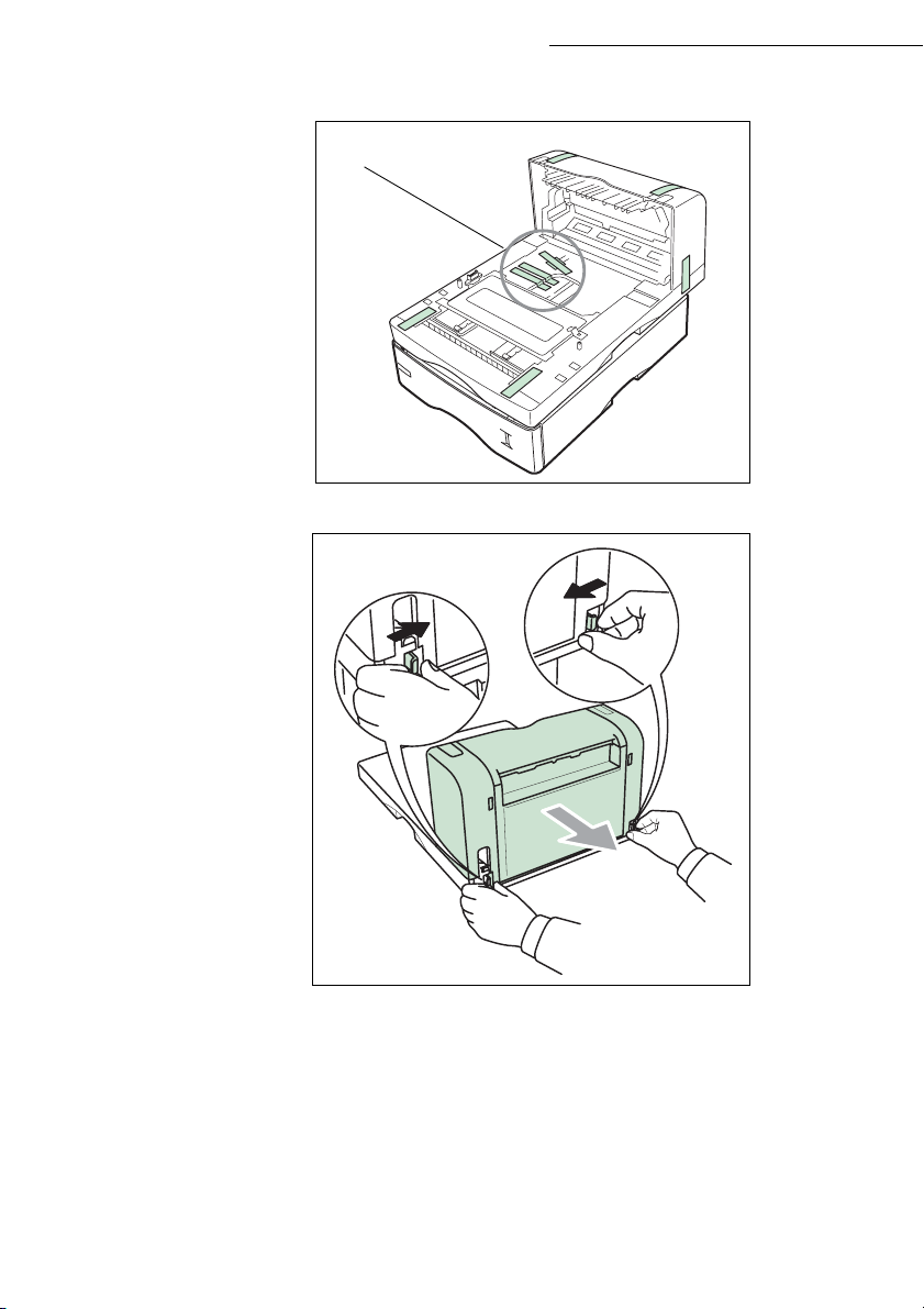
Installation
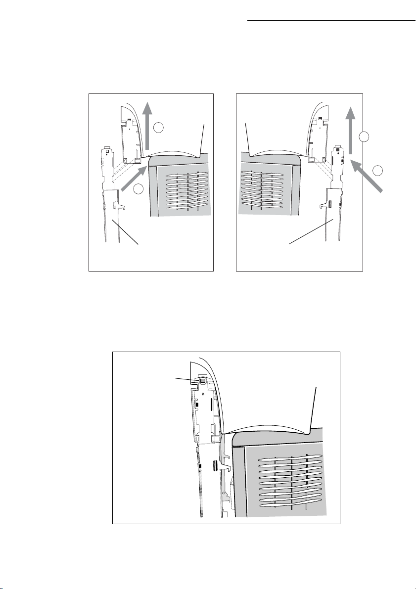
Remove the plug (A) and all the strips of fixing tape stuck onto the front/back module.
A
Remove the front/back module's rear cover by pressing it inwards (see illustration below).
1-10
Page 19
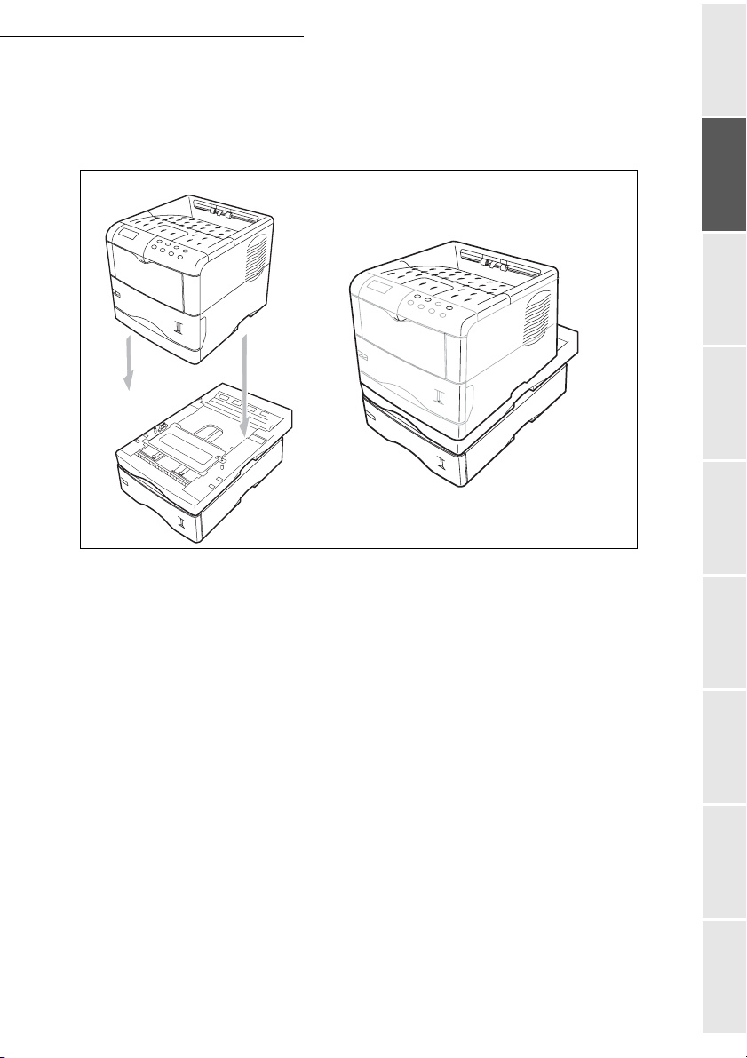
Installation
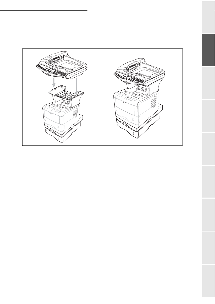
Installing the printer on top of the front/back module
Place the printer on top of the front/back module and lay it down onto this module.
Getting startedDirectoryMaintenanceSafety ContentsInstallationPrint function
Setting your
machine
1-11
Operation
Page 20
Installing the feet on the scanner/printer interface
Position the scanner/printer interface unit on top of the printer, around 3 centimetres back from
the rear.
Installation
Left
2
1
Left interface
foot
Right
Right interface
foot
2
1
Insert the scanner/printer interface feet into the slots provided for this purpose, located on both
sides at the rear of the scanner/printer interface, both of the feet have a fool-proofing device and
can only be fitted in a single place.
Once both of the feet have been positioned in their respective slots, press upwards until they clip
and then lock into place (see illustration below).
Clipping area
1-12
Page 21
Installation
Installing the scanner on top of the scanner/printer interface
Place the terminal's scanner on top of the scanner/printer interface and then lay it down.
Getting startedDirectoryMaintenanceSafety ContentsInstallationPrint function
Setting your
machine
1-13
Operation
Page 22
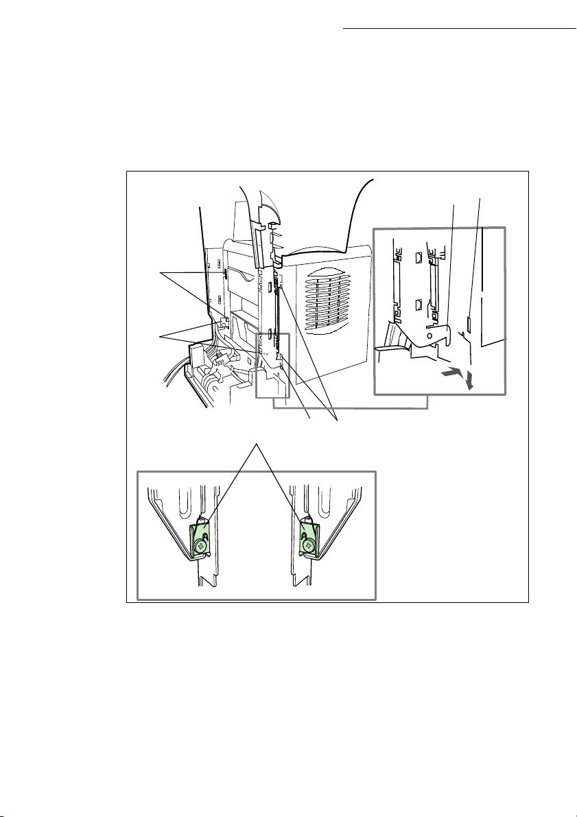
Fitting the scanner interface to the printer
Lift up the scanner/printer interface unit and then position the 4 locking tabs (B) opposite the 4
slots (A) located on the left and right-hand side at the rear of the printer. Insert the 4 tabs into
these slots then press downwards so that the unit is properly fixed onto the printer.
After fixing the unit onto the printer, make sure that the two blades on the positioning latches (C)
are in a vertical position, if not turn them so that they are in the correct position.
A
C
B
Installation
A
B
C
1-14
A
Page 23
Installation
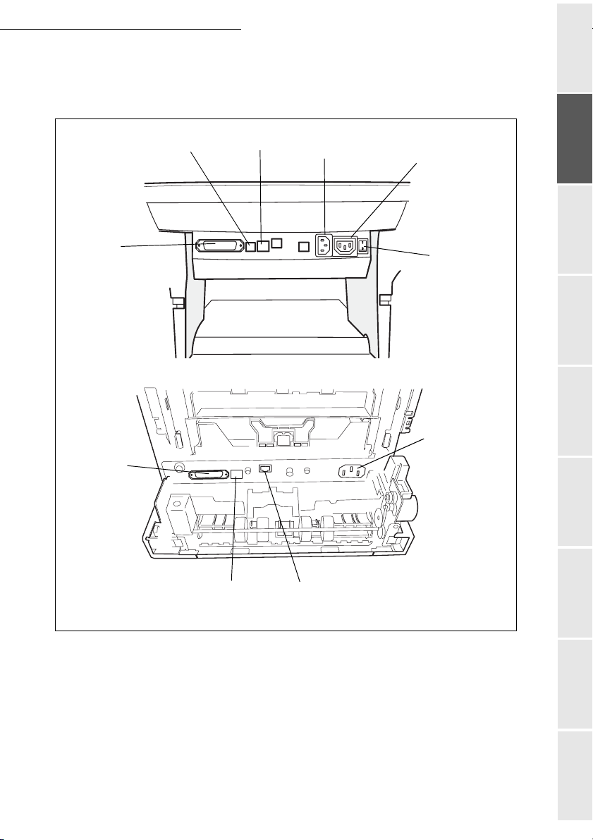
Terminal connections
If you stand at the rear of the unit you will be able to see all the available connections.
Parrallel
port
Parrallel
port
USB
Port
LAN
socket
Mains socket
Mains extension
socket
On / Off switch
Mains extension
socket
Getting startedDirectoryMaintenanceSafety ContentsInstallationPrint function
Setting your
Operation
machine
USB
Port
LAN
socket
1-15
Page 24
Installation
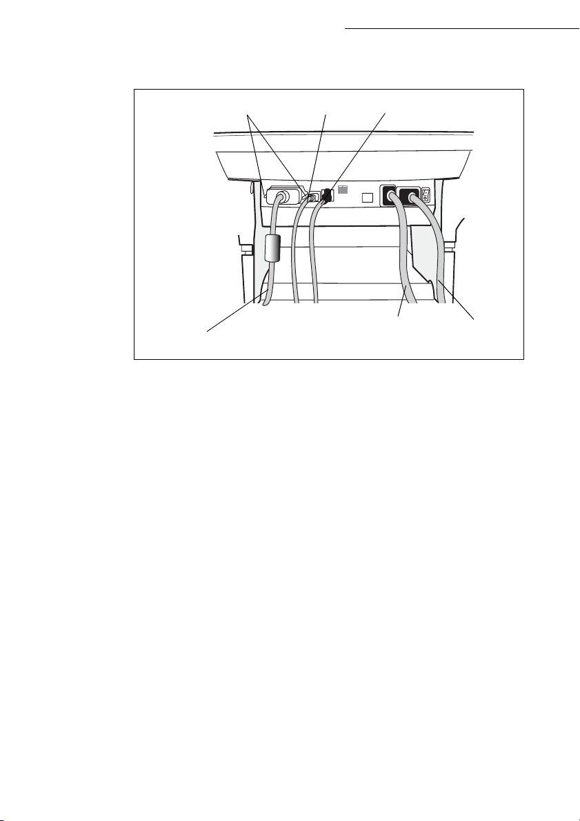
Connect your terminal's leads as shown below. Do not forget to lock the Centronics lead into
place using the 2 metal clips.
Locking clips
USB lead LAN lead
(not supplied)
(not supplied)
Centronics
lead
Mains
extension lead
scanner
mains
load
1-16
Page 25
Installation
Connecting up the scanner/printer/front/back module
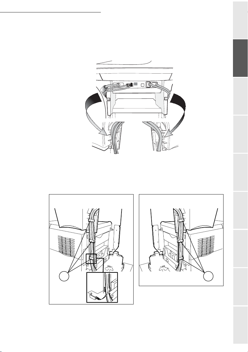
Once the various leads have been connected, position them by inserting them into the
sockets provided for this purpose in the scanner/printer interface's two side feet as shown
below.
After carefully pushing the various leads into their respective sockets, clip the fasteners (A)
onto the scanner/printer interface feet supplied with the scanner (6 cable fasteners), see
illustrations below.
Getting startedDirectoryMaintenanceSafety ContentsInstallationPrint function
Setting your
machine
A
Left
Right
Operation
A
1-17
Page 26
Installing the cable holders
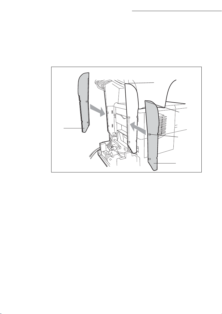
Clip the 2 cable holders (see illustration below) onto the scanner/printer interface feet to hide the
leads inside the feet.
Start by fitting the right-hand holder. Position the upper part of the holder (A) underneath the
interface (B). Bring the lower part of the holder (C) against the foot making sure that the middle
clip (D) is in the right position. Clip the whole unit together.
A
Installation
B
A
D
Then fit the left-hand holder in the same way.
1-18
C
Page 27
Installation
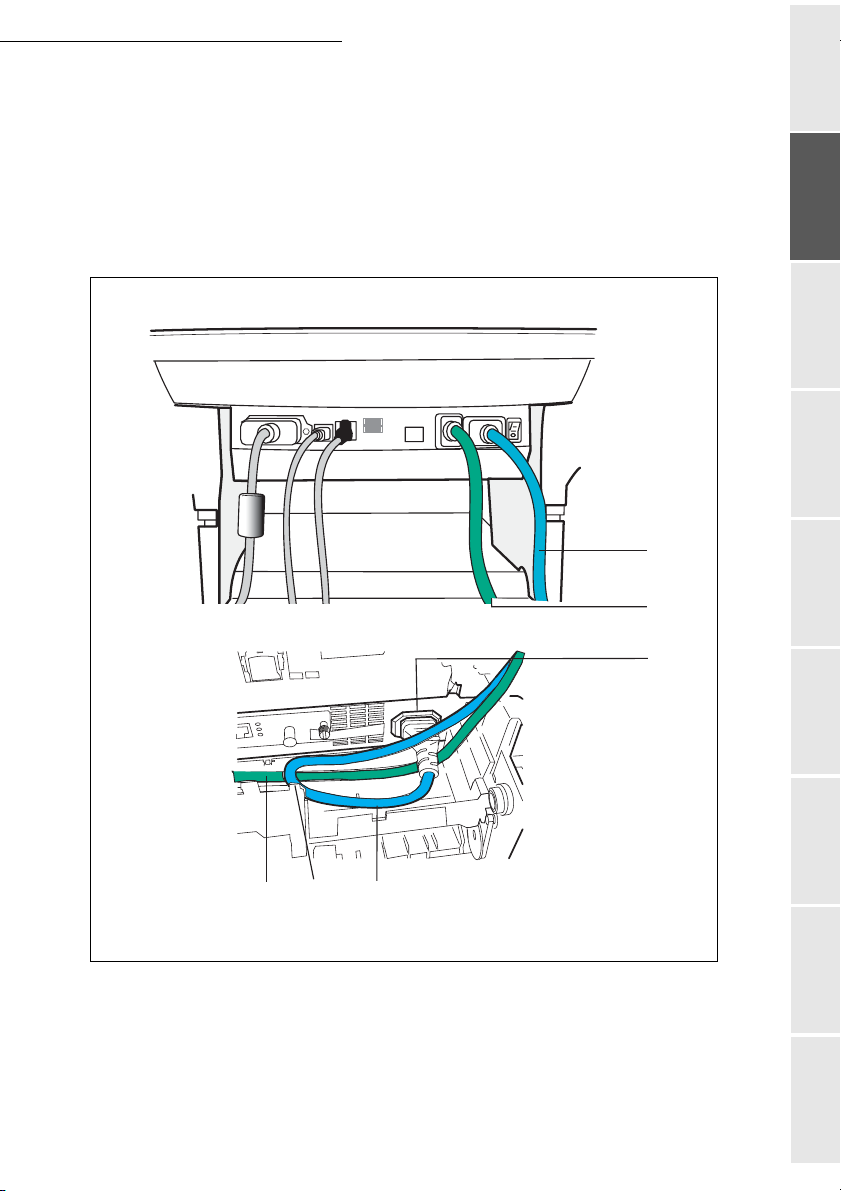
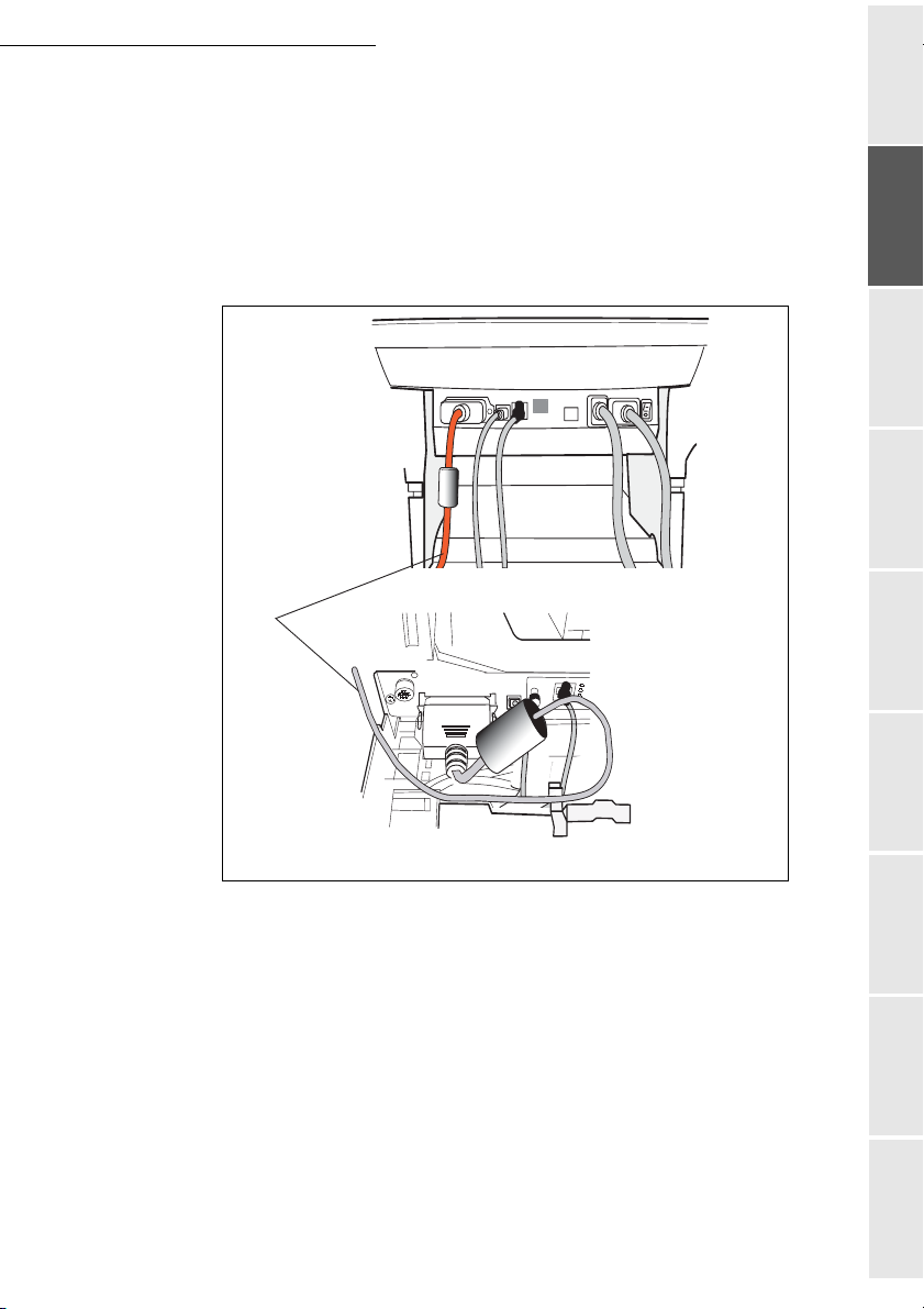
Connecting the scanner's mains lead to the printer
Connect the end of the male/female mains lead (A) to the printer's male connector (E).
Pass the scanner's mains lead (B) from underneath the printer's mains lead (A) see
illustrations below.
Make a loop with the mains lead (A) by inserting it into the grommet (D), see illustrations
below.
Getting startedDirectoryMaintenanceSafety ContentsInstallationPrint function
machine
Setting your
A
B
E
Operation
D
A
1-19
B
Page 28
Connecting the printer's LAN and USB leads
Connect the printer's LAN lead (C) and USB lead (B) as shown in the illustration below.
A
B
C
Installation
1-20
Page 29
Installation
A
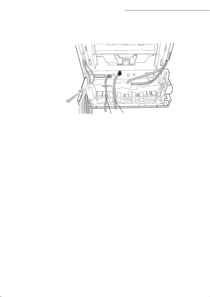
Connecting the scanner's parallel port to the printer
Connect the end of the lead (A) to the parallel port connector located on the left-hand side
at the back of the printer and lock it into place with the 2 metal tabs.
Pass the USB and LAN leads underneath the parallel lead (A).
Position the lead (A) on the bottom of the front/back module by running it over the mains
lead and the scanner line lead as shown in the illustrations below.
Getting startedDirectoryMaintenanceSafety ContentsInstallationPrint function
Setting your
machine
Operation
1-21
Page 30
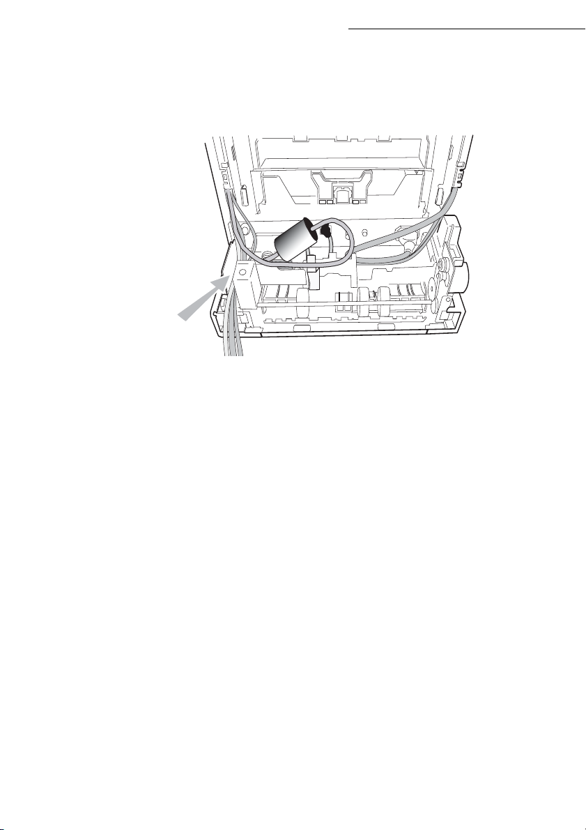
Taking the various leads out of the terminal
Once you have connected all of the terminal's leads, push them into the slot (A) provided for this
purpose on the left of the front/back module, see illustration below.
A
Installation
1-22
Page 31

Installation
Fitting the front/back module cover
Remove the two flaps (A) from the rear front/back module cover.
A
Pass the leads (mains scanner, USB and LAN) through the hole (B) which is provided for
this purpose, located on the left-hand side at the rear of the front/back module cover.
Fix the rear front/back module cover into place by clipping to its base. Make sure that the
2 clips (C) are properly locked into place.
A
Getting startedDirectoryMaintenanceSafety ContentsInstallationPrint function
machine
Setting your
Operation
B
C
1-23
Page 32

Installation
INSTALLING THE REMOVABLE COMPONENTS
This section tells you how to install the terminal's removable components.
INSTALLING THE SCANNER DOCUMENT FEEDER
Fix the document feeder into place by clicking its two tabs into the appropriate holes (A) on the
terminal.
A
1-24
Page 33

Installation
ADJUSTING THE ORIGINAL DOCUMENT
OUTPUT TRAY
Depending on the format of the document to be scanned - A4 or LGAL (LEGAL) adjust
the paper stop.
Getting startedDirectoryMaintenanceSafety ContentsInstallationPrint function
Setting your
machine
LOADING PAPER
Remove the printer paper tray.
Push the lower tray downwards until it clicks into place.
1-25
Operation
Page 34

Installation
Turn the format dial so that the desired format appears in the paper format window.
Note: If the paper format dial is set to OTHER you will need to adjust the paper format on the printer's control panel.
See the user guide.
Paper format
selector
Paper format
indicator
Adjust the paper guides to the paper format by lifting the lever (A) located on the left-hand guide.
A
1-26
Page 35

Installation
Adjust the stop which is located at the rear of the tray by pulling the lever upwards.
B5A4
Place the paper into the tray. Be careful to slide the stack under the 2 hooks located at the
bottom of the tray (A).
Getting startedDirectoryMaintenanceSafety ContentsInstallationPrint function
Setting your
machine
A
Caution - Never exceed the loading limits shown on the tray, the tray is designed to hold
500 sheets of 80g/m² paper.
Caution - Never add paper to the tray while the machine is printing.
Kinds of paper which the printer will take:
Printer paper tray 60 to 105 g/m
Manual feeder 60 to 200 g/m
2
2
Close the printer paper tray back up again.
1-27
Operation
Page 36

Installation
LOADING THE MULTIPURPOSE TRAY
If you are printing onto special paper such as 60 to 200 g/m2 maximum colour paper or transparent film
(laser printer-compatible), you should use the multipurpose tray which will hold up to 100 sheets of
paper (A4).
Open the multipurpose tray cover.
1-28
Page 37

Installation
Put the paper support into place.
Adjust the width between the guides according to the type of paper you are using.
A4
B5
LTR
A5
Getting startedDirectoryMaintenanceSafety ContentsInstallationPrint function
Setting your
machine
Put the paper in.
Operation
1-29
Page 38

Installation
INSTALLING CONSUMABLES
Open the printer top cover (A) all the way.
(A)
With the label side down, thoroughly shake the new toner container (B) (in the direction of the
arrow) ten times or more to ensure that the toner is evenly distributed inside.
1-30
(B)
Page 39

Installation
Carefully remove the protective seal [orange colored (C)] from the new toner container and
then install the container into the printer.
(C)
Push firmly on the top of the toner container at the positions marked PUSH HERE until
you hear it click into place.
Getting startedDirectoryMaintenanceSafety ContentsInstallationPrint function
Setting your
machine
Close the printer top cover.
Operation
1-31
Page 40

Installation
First open the left cover (D) on the left side of the printer.
(D)
Open the cap of the new waste toner box (E). Insert the new waste toner box as shown in the
figure. The box will be locked when it fits into place.
(E)
Close the left cover.
1-32
Page 41

Installation
WALL CONNECTIONS
Caution - Make sure that the On/Off switch is in the 0 (Off) position.
LAN CONNECTIONS
Connect the end of the LAN lead (supplied by your network administrator) into your
terminal's local network socket (please see the paragraph on Terminal connections,
page 1-15, for instructions on how to connect the scanner).
Note: the printer and the scanner may have a LAN connection. If you only have one connection, you will need a hub
or a switch.
Getting startedDirectoryMaintenanceSafety ContentsInstallationPrint function
POWER LINE CONNECTION AND SWITCH ON
Caution - Refer to safety procedures in the chapter on Safety.
Connect the end of the terminal's scanner mains lead to the mains socket on the wall (see
the paragraph on Terminal connections, on page 1-15, for instructions on how to connect
the scanner).
Set the printer's On/Off switch to the "I" (On) position then do the same with the scanner's
switch.
After a few seconds, when the printer has warmed up, the date and time will appear. To adjust the
language and time of your terminal, please see the paragraph on Setting your machine, page 3-1.
CONFIGURING THE PRINTER DRIVER
If you install the additional paper tray or the front/back module when the printer driver is already
installed, you will need to configure the printer driver on your PC.
Click on the START button, select CONTROL PANEL and then click on PRINTERS.
Right click on the MFK28 icon then choose "Properties".
Click on the peripheral's PROPERTIES tab.
Check the boxes for the options you have installed.
machine
Setting your
Operation
1-33
Page 42

Installation
1-34
Page 43

2GETTING STARTED
NAVIGATION METHODS
PRESENTATION
The navigator gives you access to the menus visible on screen.
The navigator
This navigator has 4 keys and allows you to move within the menus available on your machine.
2-1
Page 44

Moving within the menus
Function Use key Symbol used
Getting started
Enter the main menu or select the next line
in a menu.
Enter the main menu or select the previous
line in a menu.
Confirm entry and go to the following
menu.
Return to the previous menu.
Confirm and exit from the current menu.
Exit without confirming from the current
menu.
Moving within a data entry field
OK
C
Move to the right.
Move to the left.
To Use key Symbol used
2-2
Page 45

Getting started
To Use key Symbol used
Confirm your entry.
Delete a character by moving the cursor to
the left.
Confirm your entry and return to the initial
screen.
The display screen
The screen has two lines of 16 characters.
The cursor shows the line you selected.
1DIRECTORY
2 SETUP
For menus with more than two choices, use the arrows
next (hidden) lines of the menu (3,4, etc.).
ACCESS TO FUNCTIONS
Access to functions may be achieved in two ways.
• Menu-driven access.
• Direct function access.
OK
C
or of the navigator to obtain the
Getting
Setting your
DirectoryMaintenanceSafety ContentsInstallationPrint function
Operation
started
machine
Menu-driven access
You can print the guide to find out the number of a function by pressing the key or by
scrolling through the menus, as indicated below.
Press the key, the functions menu appear.
Use the or navigator arrows to move the cursor in front of the required function.
3FAX
5 PRINT
Validate your choice by pressing OK.
2-3
Page 46

When in the selected menu, use the or navigator arrows to move the cursor in front
of the required sub-function.
51 FUNCTIONS LIST
52 LOGS
Validate your choice by pressing OK.
Caution - The Duplex version cannot be used to print the guide. Therefore it can only be printed on
one side.
Direct access by number
You may print the functions list ( 51 OK) to find out the number of a function.
From the stand-by mode:
Press the key, enter the number of the required function and validate your choice by
pressing OK.
Getting started
2-4
Page 47

Getting started
GUIDE TO FUNCTION LIST
MAIN MENU 1: DIRECTORY
Fonctions Description de la fonction Page
11 OK - NEW CONTACT Enter a new contact in the directory p. 4-2
12 OK
- NEW LIST Enter a relay broadcast list p. 4-4
- MODIFY Modify a record or a list p. 4-6
13 OK
- CANCEL Delete a record or a list p. 4-6
14 OK
15 OK
- PRINT Print the directory p. 4-6
- SAVE/LOAD Store the directory on a chip card
16 OK
161 OK S
162 OK L
17 OK
18 OK
19 OK
191 OK A
192 OK I
193 OK P
194 OK DN
195 OK P
A.Inaccessible if Menu 91 SUPPLIER is on WITHOUT ACCESS
AVE Save the directory to a chip card
OAD Load the directory from a chip card
- IMPORTATION Enable directory importation by e-mail
- EXPORTATION Export the directory by e-mail
- LDAP SERVER Access to a directory server p. 4-9
DRESSE IP address or server name p. 4-9
DENTIFIER Connection identifier p. 4-9
ASSWORD Connection password p. 4-9
BASE Search database p. 4-9
ORT Connection port p. 4-9
A
A
p. 4-8
p. 4-7
started
Getting
machine
Setting your
MAIN MENU 2: SETUP
Functions Function description Page
21 OK - DATE/TIME Enter the date and the time p. 3-2
22 OK
24 OK
- NUMBER / NAME Enter your name and your number p. 3-2
- RECEPTION Reception settings
EC. PAPER Accept reception without paper p. 3-4
BR OF COPIES Number of copies of received documents p. 3-4
UPLEX Received fax printing in Recto /Verso mode p. 3-4
DJUST PAGE Adapt the print scaling p. 3-4
- NETWORKS Setting networks
REFI X Dialing prefix activation p. 3-4
OCAL NETWORK LAN prameters settings (depending of model)
ONFIGURATION Sélect configuration mode p. 3-6
DRESSE Fax IP address p. 3-7
UBNET MASK. Subnet mask p. 3-7
ATEWAY Gateway #1 address p. 3-7
DRESSE Fax IEEE address p. 3-7
ETBIOS 1 NetBIOS name 1 p. 3-7
ETBIOS 2 NetBIOS name 2 p. 3-7
OM LOGIN Domain login parameters for the Scan to Disk function p. 3-8
SER User name for login on the local network p. 3-8
ASSWORD Password for login on the local network p. 3-8
OM. NAME Domain name of the local network p. 3-8
2-5
241 OK R
242 OK N
244 OK D
245 OK A
25 OK
252 OK P
253 OK L
2531 OK C
2532 OK IP A
2533 OK S
2534 OK G
2535 OK IEEE A
2536 OK N
2537 OK N
2538 OK SRV. WINS 1 Address of the NetBIOS name server 1 p. 3-7
2539 OK SRV. WINS 2 Address of the NetBIOS name server 2 p. 3-8
254 OK D
2541 OK U
2542 OK P
2543 OK D
DirectoryMaintenanceSafety ContentsInstallationPrint function
Operation
Page 48

Getting started
MAIN MENU 2: S
ETUP
Functions Function description Page
29 OK - TECHNICALS Technicals parameters p. 3-5
20 OK
203 OK L
- GEOGRAPHICAL Geographical settings p. 3-2
ANGUAGE Choice of language
p. 3-2
MAIN MENU 3: FAX
Functions Function description Page
38 OK - FAX ANSW. Control of fax answering machine p. 3-3
39 OK
391 OK A
392 OK
393 OK C
- REROUTING Rerouting of received messages p. 5-4
CTIVATION Rerouting activation p. 5-4
DESTINATION Choice your destination p. 5-4
OPY Printing activation of rerouting fax p. 5-4
MAIN MENU 5: PRINT
Functions Function description Page
51 OK - FUNCTIONS LIST Function list printing p. 5-15
52 OK
53 OK
54 OK
55 OK
- LOGS Print TX and RX logs p. 5-15
- DIRECT ORY Print the directory p. 4-6
- SETUP User parameters printing p. 5-16
- COMMANDS Commands list printing (see 65 OK)
MAIN MENU 6: COMMANDS
Functions Function description Page
61 OK - PERFORM Perform a command p. 5-9
62 OK
63 OK
64 OK
65 OK
- MODIFY Update of command p. 5-9
- CANCEL Delete a command p. 5-9
- PRINT Printing of a document in wait queue p. 5-10
- PRINT LIST Printing of the command list p. 5-10
MAIN MENU 8: ADVANCED FCT
Functions Function description Page
80 OK - CALIBRATION Scanner calibration p. 7-11
- LOCK Activate an access limitation lock p. 5-17
81 OK
811 OK L
812 OK L
813 OK L
814 OK L
82 OK
821 OK S
822 OK R
823 OK S
824 OK D
825 OK P
83 OK
831 OK C
833 OK L
OCKING CODE Locking code p. 5-17
OCK KEYBD. Activate keyboard lock p. 5-17
OCK NUMBER Activate dialling lock p. 5-17
OCK PARAMETERS Activate Internet settings lock p. 5-18
- COUNTERS See the activity counters p. 5-16
ENT PAGES Printed pages counter p. 5-16
ECEIVED PG Local copies counter p. 5-16
CANNED PAGE Sent pages counter p. 5-16
UPLEX SCAN Received pages counter p. 5-16
RINTED PG Printed pages counter p. 5-16
- FAX SERVER Fax server settings
ONNECT TYPE Connection type choice p. 3-10
OCK Defining and activating an access limiting lock p. 3-11
2-6
A
p. 3-10
Page 49

Getting started
MAIN MENU 8: A
DVANCED FCT
Functions Function description Page
834 OK FAX -SERVER NAME Fax server name p. 3-11
835 OK IP A
836 OK D
84 OK
841 OK R
842 OK Z
843 OK A
844 OK O
845 OK C
846 OK L
847 OK B
85 OK
851 OK P
852 OK P
853 OK P
854 OK S.F
855 OK F
86 OK
DRESS Fax server IP adress p. 3-11
OMAIN NAME Fax server domain name p. 3-11
- COPY CIS scanner settings p. 5-13
ESOLUTION Resolution type choice p. 5-13
OOMING Zoom setting p. 5-13
SSEMBLED Assembled or not copy choice p. 5-13
RIGIN Origin setting p. 5-13
ONTRAST Contrast setting p. 5-13
UMINOSITY Luminosity setting p. 5-14
INDING Binding type choice p. 5-14
- SCAN. & PRINT Réglages imprimante p. 5-14
APER Type of paper choice p. 5-14
APER TRAY Paper tray choice p. 5-14
APER SAVE Paper save activation mode p. 5-14
MARGINS Set margins p. 5-14
LATBED MARG Sheet-feed scanner margins setting p. 5-15
- CONSUMABLES Consumables status p. 7-2
A. Depending on option
MAIN MENU 9: INTERNET
Functions Function description Page
91 OK - SUPPLIER Choix du fournisseur d’accès p. 3-18
92 OK
- INIT. ETHERNET Initialisationof your Provider
921 OK M
9211 OK I
9212 OK P
9213 OK E-
922 OK S
ESS. SERV p. 3-12
DENTIFIER Message service identifier
ASSWORD Message service password
MAIL ADR Message service E-Mail address
ERVERS SMTP, POP3 and DNS parameters p. 3-13
9221 OK SMTP SMTP server
9232 OK POP3 POP3 server
9233 OK DNS 1 Primary DNS
9224 OK DNS 2 Primary DNS
923 OK SMTPA
9231 OK A
93 OK
- IMMED ACCES
- SETTINGS
94 OK
UTHENT. SMTP authentification access parameters p. 3-13
CTIVATION SMTP authentification activation
Immediat access to ISP
Internet settins
A
941 OK CONNEC. TYPE Select connection type p. 3-15
942 OK S
943 OK P
944 OK D
945 OK E-
946 OK P
95 OK
96 OK
END TYPE Select transmission type p. 3-15
ERIOD Select the period of connection p. 3-15
EPOSIT NOTI Select to print a deposit notice p. 3-16
MAIL ADDR Choose the address to which an e-mail will be sent p. 3-16
RINT Print Internet settings p. 3-16
- E-MAIL
- TRI MAILS
Send an E-Mail
Select the reception type
A
A.These menus will appear only with valid ISPN setting
A
A
A
p. 3-12
p. 3-18
p. 5-6
p. 3-16
Getting
Setting your
DirectoryMaintenanceSafety ContentsInstallationPrint function
Operation
started
machine
2-7
Page 50

PRINT CONSOLE NAVIGATION BASICS
NAVIGATING THE MENUS
Control panel keys
The keys on the console are used to configure the printer. Some keys also have secondary functions.
Getting started
GO
Note: Any settings made using these keys affect only the current interface.
Key Function
• Connects and disconnects the printer.
GO
• Prints and then ejects a page.
• Cancels specific errors.
• Cancels a print job.
• Reinitialises the numerical values or cancels a configuration procedure.
• Stops the alarm sound triggered by an error.
• If you press this key during mode selection: the configuration ends and
the printer returns to Ready.
• Selects the emulation, font and character encoding, in order to read a
CompactFlash card, etc.
Used to access a section or to enter numerical values. The > and < keys are
used to access or exit a subsection in some of the control procedures.
Used to access a section or to enter numerical values. The > and < keys are
used to access or exit a subsection in some of the control procedures.
ENTE
?
R
Used in the same way as the < key in the mode selection function.
2-8
Page 51

Getting started
Key Function
• Used in the same way as the > key in the mode selection function.
• Displays on-line help messages on the screen when there is a paper
jam:
If you press this key when the printer is
tions about the on-line help messages.
If you press this key when the on-line help is displayed:
the on-line help is cancelled.
Confirms the numerical values and other selections.
ENTE
?
R
ACCESS TO FUNCTIONS
Ready : it displays explana-
started
Getting
This section explains how to use the menu selection system. The MENU key on the operator
console allows you to use the menu to configure or adapt the printer environment, making settings
such as the number of copies to be made, the emulation, etc. depending on your own specific
needs. You can make these settings when the printer screen shows Ready.
Note: The printer applies the most recent settings sent from the application software or from the printer driver,
and these always take priority over any settings made from the operator console.
To navigate vertically within the functions, use the and keys (access the menu shown by
repeatedly pressing one of the keys).
To navigate horizontally within the functions, use the > and < keys. To change or confirm the
configuration of a component, press the ENTER key.
Printing out the menu guide
The list of menus may vary according to which options you have installed.
You can print out the print menu guide by moving within the menus as shown below.
MENU - - PRINT MENU STRUCTURE
Press ENTER, a blinking "?" appears.
Press ENTER again to start printing.
Setting your
DirectoryMaintenanceSafety ContentsInstallationPrint function
Operation
machine
2-9
Page 52

Getting started
GUIDE TO FUNCTIONS
Functions Description of the function Page
- PRINT MENU MAP Print out the menu guide p. 2-10
- PRINT STATUS PAGE Print out the printer configuration p. 6-4
- INTERFACE p. 6-16
ARALLEL Parallel interface configuration
P
USB USB interface configuration p. 6-16
O
PTIONAL Network interface configuration p. 6-16
ETWARE Turn this menu on if you are using the Netware
N
TCP/IP Turn this menu on if you are using the TCP/IP protocol
THERTALK Turn this menu on if you are networking with a
E
O
PT. STATUSPAGE When this menu is turned on, the network
- EMULATION Select emulation type p. 6-11
- FONT p. 6-13
F
ONT SELECT Select font
ODE SET Select character encoding
C
IST OF INTERNAL FONTS List of available fonts
L
- PAGE SET
COPIES Set the number of copies to be made p. 6-14
RIENTATION Choose the paper orientation p. 6-14
O
LF A
CTION Action following a line break p. 6-17
CTION Action following a carriage return p. 6-18
CR A
IDE A4 Optimise the number of characters per line p. 6-18
W
- PRINT QUALITY Sets the print quality
- OPT. ROM
- RAM DISK :ODE
- MEMORY CARD
- PAPER HANDLING
ODE Image antialiasing mode p. 6-15
KIR M
RAFT MODE Draft mode p. 6-16
D
R
ESOLUTION Choose resolution type p. 6-16
RINT DENSITY Choose print density p. 6-18
P
MP TRAY MODE Multipurpose tray operating mode p. 6-10
RAY SIZE Choose the paper format in the multipurpose tray p. 6-7
MP T
RAY TYPE Choose the paper type in the multipurpose tray p. 6-10
MP T
C
ASSETTE 1 TYPE Choose the paper type in tray 1 p. 6-8
ASSETTE 2 TYPE Choose the paper type in tray 2 (depending on option) p. 6-8
C
EED SELECT Choose the source tray p. 6-10
F
D
UPLEX MODE Switch front/back mode on
TACK SELECT
S
OVERRIDE A4/LT Force the printing of letter documents in A4 format p. 6-11
T
YPE ADJUST
PAPER WEIGHT Choose the paper weight p. 6-9
protocol
Macintosh
configuration page is printed out at the same time as
the printer status page.
2-10
Page 53

Getting started
Functions Description of the function Page
DUPLEX PATH
RESET TYPE
- LIFE COUNTERS Number of pages printed counter p. 6-18
- OTHERS
MSG LANGUAGE Choose the language in which messages will be
displayed
F
ORM FEED Set the time before printing out an incomplete page. p. 6-19
LEEP TIMER Set the time before entering standby mode p. 6-19
S
LEEP MODE Switch the standby mode on p. 6-19
S
P
RINT
PRINTER RESET Reinitialise the settings to their default values p. 6-19
ESOURCE PROT. Save downloaded PCL6 parameters p. 6-19
R
B
UZZER Turn the error alarm on or off p. 6-20
UTO CONTINUE Continue printing after error p. 6-20
A
UTO CONTINUE TIMER Waiting time before continuing p. 6-20
A
F
INISHING Manage front/back errors p. 6-21
UPLEX
D
SERVICE p. 6-21
P
RINT Print out the status page or log
EVELOPER
D
DRUM-CTRL
D
RUM
p. 6-18
started
Getting
machine
Setting your
2-11
DirectoryMaintenanceSafety ContentsInstallationPrint function
Operation
Page 54

Getting started
2-12
Page 55

3SETTING YOUR
Fine
Sfine
Photo
MACHINE
MAIN SETTINGS
At machine powerup, the screen displays:
FRI 31 DEC 23:59
PLEASE WAIT
Fine
Sfine
Photo
You have to set the date and time, language parameter and verify the other parameters listed
below.
3-1
Page 56

BEFORE TRANSMISSION
Date/Time
At any moment you may change the date and time on your fax machine.
To change the date and time:
Enter the numbers of the required time and date one after another,
(for example November 8 2004 at 9h33, press 0811040933) and press OK to confirm.
Your terminal number/your name
Setting your machine
21 OK - SETUP / DATE/TIME
Your fax will print out your fax number on each document it transmits if you save this number and if
the machine is set to
page 3-5).
To save your fax number and your name:
SENDING HEADER (please see the paragraph on Technical parameters,
The number field appears and press OK to confirm.
Enter your name (20 characters max) then press OK to confirm.
Geographical settings
Language
This setting enables you to choose a language other than that imposed by the COUNTRY setting.
To select the language:
Select the required option and press the OK key to confirm.
Local prefix
The prefix is to define when your terminal is localized on a local area network and that you send
documents via a compatible fax server.
Programming your fax with the local prefix consists of two steps:
• defining the minimal size (or equal) of the company’s outside numbers,
• defining the outgoing local prefix of the network. This prefix will automatically be added as soon
as an external number is dialled.
Caution - If you define a local prefix, do not add it to the numbers stored in the directory, it will be
automatically dialled with each number.
22 OK - SETUP / NUMBER / NAME
203 OK - SETUP / GEOGRAPHICAL / LANGUAGE
3-2
Page 57

Setting your machine
Defining the minimal size and the local prefix
252 OK - SETUP / NETWORKS / PREFIX
You can change the default value for the minimal size of the company’s outside numbers
and validate with OK. The minimal size will range between 1 and 30.
Enter the outgoing local prefix of the company’s telephone network (maximum
5 characters) and validate with OK.
BEFORE RECEPTION
Fax answering machine
The Fax answering machine allows you to keep confidential documents in storage and to avoid
printing them as you receive them.
The "Fax Messages" indicator light lets you know the state of your Fax answering machine:
• Light on: the answering machine is on.
• Blinking: your fax has documents in storage or is in the process of receiving faxes.
• Light off: memory full, the terminal cannot receive any more documents.
You can assure document confidentiality by using the 4 digit access code. Once saved, you will
require this access code for:
• printing fax messages in memory,
• activate or deactivate the fax answering machine.
SommaireInstallation
Getting startedDirectoryMaintenanceSafety ContentsInstallationPrint function
Setting your
machine
Saving an access code
383 OK - FAX / FAX ANSW. / ANSWER CODE
Enter the code (4 digits) and confirm with OK.
Activating or deactivating the answering machine
382 OK - FAX / FAX ANSW. / ACTIVATION
If you saved an access code for your fax answering machine, enter it and validate with OK.
Select the required option WITH or WITHOUT answering machine and confirm you choice
with OK.
Print fax messages stored in the memory
381 OK - FAX / FAX ANSW. / PRINT
If you have defined an access code for your fax answering machine, enter it and press OK.
Documents received and stored in the memory are printed.
3-3
Operation
Page 58

Reception without paper
Your fax offers you the possibility to either accept or refuse document reception if your printer is
unavailable (no paper...).
If your fax printer is unavailable, you may choose between two modes of reception:
• reception mode
• reception mode
To select the reception mode:
WITHOUT PAPER, your fax saves the incoming messages in the memory,
WITH PAPER, your fax refuses all incoming subscribers.
241 OK - SETUP / RECEPTION / REC. PAPER
Select the option WITH PAPER or WITHOUT PAPER and confirm your choice with OK.
Remark : Paper out is indicated by a beep and a message on the screen.
Received faxes are then stored in memory (icon "Fax messages" flashing) to be printed as soon as you add paper
into the feeder.
Number of copies
You may print incoming documents more than once (1 to 99).
To set the number of each document received:
242 OK - SETUP / RECEPTION / NBR OF COPIES
Enter the wanted number of copies and confirm with OK.
At each document reception, your fax will print the number of copies requested.
Setting your machine
Duplex printing
This function is only available if you have previously installed the duplex module and the additional
paper tray at the back of your terminal.
After installing the Duplex module at the back of your multi-function terminal, you can print faxes
received in two ways:
• SINGLE SIDED
• DOUBLE SIDED
All faxes received are printed according to the mode selected from the menu, no matter how the duplex
key is set.
To select the fax print mode :
Select the required option SINGLE SIDED or DOUBLE SIDED and validate your choice with
the OK key.
Adjust to page
This option allows you to print out documents automatically adjusting them to the page format.
To turn adjust to page mode on:
Select the WITH option and confirm your choice using the OK key.
244 OK - SETUP / RECEPTION / DUPLEX
245 OK - SETUP / RECEPTION / ADJUST PAGE
3-4
Page 59

Setting your machine
TECHNICAL PARAMETERS
As delivered your fax is preset by default. However, you may adjust it to meet your requirements
by resetting the technical parameters.
To set the technical parameters:
29 OK - SETUP / TECHNICALS
Select the desired parameter and confirm with OK.
With the keys or , modify the parameter settings by following the table below and
press OK.
P a r a m e t e r S e t t i n g S i g n i f i c a t i o n
1 - SCANNING
MODE
8 - ECO ENERGY
10 - RX HEADER
1 - NORMAL
2 - FINE
3 - SFINE
4 - PHOTO
1 - WITHOUT
2 - DELAY 5 MIN
3 - DELAY 15 MIN
4 - DELAY 30 MIN
5 - DELAY 60 MIN
1 - WITH
2 - WITHOUT
Default value of the scan mode resolution for the documents
to be transmitted.
Choosing the printer standby delay: the printer will switch to
standby after a delay (in minutes) of NON-operation or during
the period of time of your choice.
If this parameter is on, all documents received by your fax
will include the subscriber’s header with his name, number (if
available) fax print date and the page number.
SommaireInstallation
Getting startedDirectoryMaintenanceSafety ContentsInstallationPrint function
Setting your
machine
70 - NET VALID
74 - ERASE
MAILBOX
76 - ATTACHMENT
FORMAT
06:01 TO 21:59
1 - WITH
2 - WHITHOUT
1 - IMAGE
2 - PDF
This parameter lets you modify the period when the fax
connects automatically to the Internet.
This menu is available only if the connection type is set to
PERIODIC ( 941).
When the fax machine receives an e-mail with an attachment
and cannot open it, it erases the message from the ISP MBX,
prints and transmits with a notice of uncomprehension to the
message sender.
At E-mail reception, the fax does not destroy the MBX
message, it prints a notice of uncomprehension asking you
to recuperate this message with your computer equipment.
This parameter is useful only if you have PC equipment. The
memory capacity is limited, you need to empty your MBX or
else new messages may not be received.
Default format of document sent on the Internet :
PDF : monochrome or colour
IMAGE : monochrome (TIFF) or colour (JPEG)
3-5
Operation
Page 60

P a r a m e t e r S e t t i n g S i g n i f i c a t i o n
Setting your machine
77 - LAN SPEED
80 - TONER SAVE
AUTO
100 FULL
100 HALF
10 FULL
10 HALF
1 - WITH
2 - WHITHOUT
To define the communication speed of the peripheral units in
relation to the implemented Local Area Network (LAN).
Makes printing lighter to save toner cartridge ink
LOCAL AREA NETWORK SETTINGS
Your terminal is a new generation machine that will be part of your local network just like a PC. Its
built-in local network access card will enable you to send documents through an SMTP/POP3 local
message server (internally or externally, depending on the settings of your message server).
To benefit from all the available network options, you should make the following settings, described in
the sections below:
• local network settings, to introduce your fax machine into your local network.
• message service settings, for all your faxes and E-mails to be automatically managed by your
message server.
Caution - Although rather simple, network settings sometimes require a sound knowledge of your
own computer configuration. If that is administrated by anyone in your company, we recommend you
ask that person for the settings described below.
LOCAL NETWORK SETTINGS
Automatic configuration
We recommend that you carry out a manual configuration of your terminal. The automatic
configuration of the local network settings may be considered, if your local network features a DHCP
or BOOTP server that can dynamically assign addresses to the peripheral devices present on the LAN.
To automatically configure the local network settings:
2531 OK - SETUP / NETWORKS / LOCAL NETWORK / CONFIGURATION
Choose AUTOMATIC and press OK to confirm. The terminal scans the local network for a DHCP
or BOOTP server that can assign it its settings dynamically (the message
displayed).
Once the message SELF-CONF has disappeared, check for the IP Address, Sub-network mask
and Gateway address. If these are missing, you should carry out a manual configuration (see
below).
SELF-CONF is
3-6
Page 61

Setting your machine
Manual configuration
To configure your terminal manually, you should obtain the usual information used to set a
peripheral device (IP address, sub-network mask, network and gateway address).
To configure the local network setting manually:
2531 OK - SETUP / NETWORKS / LOCAL NETWORK / CONFIGURATION
Choose MANUAL and press OK to confirm.
IP address
2532 OK - SETUP / NETWORKS / LOCAL NETWORK / IP ADRESSE
Enter the IP address of your terminal and press OK to confirm.
Sub-network mask
2533 OK - SETUP / NETWORKS / LOCAL NETWORK / SUBNET MASK.
Enter the sub-network mask of your terminal and press OK to confirm.
Gateway address
2534 OK - SETUP / NETWORKS / LOCAL NETWORK / GATEWAY
Enter the IP address of the network gateway and press OK to confirm.
IEEE address (or Ethernet address) or MAC address
2535 OK - SETUP / NETWORKS / LOCAL NETWORK / IEEE ADRESSE
The Ethernet card of your terminal already has an unmodifiable, yet consultable, IEEE address.
SommaireInstallation
Getting startedDirectoryMaintenanceSafety ContentsInstallationPrint function
Setting your
machine
NetBIOS
The NetBIOS name, which can be used with the network options, are used to identify your
terminal machine from a PC connected to a local network (for instance with the name
"IMP-NETWORK-1"
2536 OK - SETUP / NETWORKS / LOCAL NETWORK / NETBIOS 1
2537 OK - SETUP / NETWORKS / LOCAL NETWORK / NETBIOS 2
Enter the selected name (15 characters max) and press OK to confirm.
The WINS1 and WINS2 servers, used with the network options, allow access to terminals on
other sub-networks by means of their NetBIOS name.
These two addresses must be filled in for the Scan To Disk function.
2538 OK - SETUP / NETWORKS / LOCAL NETWORK / SRV. WINS 1
2539 OK - SETUP / NETWORKS / LOCAL NETWORK / SRV. WINS 2
Enter the IP address of each server, then validate with OK.
Remark : If the terminal is set up in Automatic configuration mode (2531), these addresses can be filled in auto-
matically by certain DHCP servers.
3-7
Operation
Page 62

Setting your machine
Case of connection to a domain (for instance with Windows NT,
2000 or XP)
The terminal can identify itself on the local network by using the parameters of a user account, before
it can, among others, archive documents by means of the Scan to Disk function.
Once these parameters have been filled in, they will be used by default, if you do not declare a user
name and password when using the function.
Login user name
2541 OK - SETUP / NETWORKS / DOM LOGIN / USER
Enter the user name for login on the local network, then validate with OK.
Login password
2542 OK - SETUP / NETWORKS / DOM LOGIN / PASSWORD
Enter the password for login on the local network, then validate with OK.
Nom de domaine
2543 OK - SETUP / NETWORKS / DOM LOGIN / DOM. NAME
Enter the domain name of the local network, then validate with OK.
PRINT FUNCTION SETTINGS
The printer can be connected to the local network as it has its own IP address.
Updating network settings
The print console allows you to:
• turn TCP/IP, NetWare and EtherTalk on or off
• turn DHCP on or off
• enter the IP address, the subnet mask address and the default gateway address.
To check or change the network card settings:
Press the MENU key.
Repeatedly press the or keys until INTERFACE appears.
One of the interface names below appears, showing that it is the current interface.
•P
ARALLEL (default setting)
•USB
• Optional (when the network card is installed)
Press ENTER, a blinking "?" appears.
3-8
Page 63

Setting your machine
Repeatedly press the keys or until OPTIONAL appears.
NTER.
Press E
Press the > key.
This example shows how to switch the TCP/IP protocol on to connect the terminal to the
network. You can switch Netware or EtherTalk on in the same way.
If TCP/IP is OFF. Press E
Press E
NTER again.
NTER, a blinking "?" appears. Select ON using the or keys.
Automatically configuring IP settings
You can make these settings when the TCP/IP protocol is on. We recommend that you manually
configure your terminal. However, local network settings can be automatically configured if you
have a DHCP or BOOTP server on your local network which can dynamically distribute
addresses to peripherals on the LAN.
To automatically configure network local settings:
MENU - - INTERFACE > - - TCP/IP > DHCP
Press ENTER, a blinking "?" appears.
Select ON using the or , then press ENTER.
Press the MENU key.
Switch your terminal off and then back on again. You have now finished configuring the
IP address
Manually configuring IP settings
SommaireInstallation
Getting startedDirectoryMaintenanceSafety ContentsInstallationPrint function
Setting your
machine
You can make these settings when the TCP/IP protocol is on.
To configure your terminal manually, you will need the usual information for setting up a
peripheral (IP address, subnet mask and gateway address).
To manually configure network local settings:
MENU - - INTERFACE > - - TCP/IP > DHCP
Check that DHCP is set to OFF. If not press ENTER, then select OFF with the or . keys
NTER.
Press E
Press .
Press ENTER to enter the IP address. A cursor (_) starts to flash in the right-hand segment
(3 figures). Press the key to increment the value and the key to decrement it. Once
you have set the value for the right-hand segment, press the < key to place the cursor in the
next segment. Again, press the key to increment the value and the key to decrement
it. Proceed in the same way for all of the segments. Press E
been set up.
NTER once all the segments have
Press .
Enter the subnet mask address in the same way as for the IP address.
Press .
Enter the gateway's IP address in the same way as for the IP address.
3-9
Operation
Page 64

Press the MENU key.
Switch your terminal off and then back on again. You have now finished configuring the IP
address.
Remark : Other print-related settings are described in the Print Functions chapter.
REMOTE CONFIGURATION
You can configure the same settings either remotely or locally.
System requirements
To remotely configure your machine you will need:
• a Web browser (preferably Internet Explorer version 4),
• to make the Local Network settings for your machine (IP address, subnet mask, etc.). You should
ask your network administrator for these settings. Once you have this information, please see the
paragraph on Local network settings, page 3-6 on how to fill out the necessary fields.
Accessing the Web Server
Open a Web browser from a PC registered on the network.
Enter the IP address of the terminal you want to configure in the Address field.
Confirm by pressing ENTER.
The welcome window is displayed, choose the interface language.
Change the settings of your choice on the screen then confirm.
Setting your machine
FAX SERVER (DEPENDING ON OPTION)
You can send telecopies to a fax machine which is compatible with your terminal. This typ e of emission
is only possible if a fax server is installed on your LAN network, and if the "Fax Server" function is
activated on your terminal (menu 83).
Access to Connexion Type
831 OK - ADVANCED FCT / FAX SERVER / CONNECT TYPE
Select one of the following connection option: DISABLE, EMAIL or DIRECT then validate by
pressing the OK key.
3-10
Page 65

Setting your machine
Locking Fax Server Parameters
This function allows you to lock the fax server access.
833 OK - ADVANCED FCT / FAX SERVER / LOCK
Entering the access locking code
8331 OK - ADVANCED FCT / FAX SERVER / LOCK / LOCKING CODE
Enter your previous four-digit interlock code on the keypad and validate by pressing the
OK key.
Enter the new four-digit interlock code and validate by pressing the OK key.
Confirm the new four-digit interlock code and validate by pressing the OK key.
Activate the access locking
8332 OK - ADVANCED FCT / FAX SERVER / LOCK / VER. ACCES
Enter your interlock code and validate by pressing the OK key.
Using the or keys of the navigator, choose the WITH option.
Validate by pressing the OK key.
Setting the Fax Server Name
834 OK - ADVANCED FCT / FAX SERVER / FAX-SERVER NAME
Enter the name of the fax server.
Validate by pressing the OK key.
Setting the Fax Server IP adress
835 OK - ADVANCED FCT / FAX SERVER / IP ADRESS
Enter the IP adress of the fax server.
Validate by pressing the OK key.
SommaireInstallation
Getting startedDirectoryMaintenanceSafety ContentsInstallationPrint function
Setting your
Operation
machine
Setting the Fax Server Domain Name
836 OK - ADVANCED FCT / FAX SERVER / DOMAIN NAME
Enter the Domain Name of the fax server.
Validate by pressing the OK key.
3-11
Page 66

Setting your machine
MESSAGE SERVICE AND THE INTERNET
Your terminal lets you send and receive documents and E-mails from subscribers throughout the world
over the Internet.
An E-mail is an electronic message sent over the Internet, to an E-mail address (which is a personal
Internet mailbox).
Access to the Internet is possible thanks to the local network settings.
Before worldwide transmission, you must:
• check that all initialisation parameters correspond to those provided by the network adminis-
trator,
• perform the proper settings, if needed, for the Internet connection.
You may then connect yourself to the Internet to send and receive fax-Internet or E-mails. Both
operations will be performed during a connection.
INITIALISATION PARAMETERS
You must define or, at least check all parameters needed to identify yourself with the local network.
Your network administrator will provide you with these parameters.
The parameters are divided in 3 categories:
• message service, allows you to define the message service identifier, the message service password and the E-Mail address,
• servers, allows you to identify the name of the OP address of Internet SMTP providers (send) and
POP3 (MBX reception) and the address of DNS 1 and DNS 2 servers. The server address is made
up of 4 groups of 3 digits maximum, separated by dots.
• SMTP Authentification, used to activate the authentification protocol when the SMTP server
used requests this to end e-mails.
Access to connection and message service parameters
91 OK - INTERNET / SUPPLIER
Select LOCAL NETWORK to show the connection parameters and validate by pressing the
OK key.
Choosing
Enter Email IDENTIFIER, press OK.
Enter Email PASSWORD, press OK.
Enter E-MAIL ADR, press OK.
NO ACCESS disables access to Internet functions OK.
921 OK - INTERNET / INIT. ETHERNET / MESS. SERV
3-12
Page 67

Setting your machine
Access to servers parameters
922 OK - INTERNET / INIT. ETHERNET / SERVERS
Enter SMTP, press OK.
Enter POP3, press OK.
Enter DNS 1 (primary), press OK.
Access to the authentification SMTP parameters
923 OK - INTERNET / INIT. ETHERNET / SMTPAUTHENT.
In the ACTIVATION menu, select WITH to activate SMTP authentification then validate with
OK key.
In the PARAMETERS menu, select ID.MESS.SERV to keep the same identification
parameters as in the messaging service or AUTHENT. SPEC. to define other identification
parameters, then validate with Access to SMTP authentification parameters by pressing OK key.
When you select AUTHENT. SPEC, carry out the two following operations
Enter the IDENTIFIER then validate with OK key.
Enter the PASSWORD then validate with OK key.
Sample local network settings for the terminal
Your access provider should give you the following information:
CONNECTION IDENTIFIER: demo jt12
CONNECTION PASSWORD: *****
E-MAIL ADDRESS: demo2@company.com
SERVER:
SMTP mail.company.com
POP mail.company.com
DNS 1 103.195.014.001
DNS 2 103.195.014.002
Non-functional data given by way of example.
SommaireInstallation
Getting startedDirectoryMaintenanceSafety ContentsInstallationPrint function
Setting your
Operation
machine
3-13
Page 68

You should then complete the following MENUS on your fax machine:
91 SUPPLIER LOAL NETWORK
MESS. SERV
9211 EMAIL ID demo jt 12
9212 EMAIL PASSWORD *****
9213 E-MAIL ADR demo2@gofornet.com
SERVERS
9221 SMTP mail.gofornet.com
9222 POP3 mail.gofornet.com
9223 DNS 1 103.195.014.001
9224 DNS 2 103.195.014.002
SMTP AUTHENT.
9231 ACTIVATION WITHOUT
Your terminal is now configured.
Setting your machine
SETTINGS
The settings are divided into several categories:
•the standard settings define the connection type and frequency to the Internet as well as the
transmission type for your documents,
•the E-mail sorting defines treatment for all stored E-mail messages received.
3-14
Page 69

Setting your machine
Standard settings
Your machine has two types of settings that let you define:
• The type and frequency of the connection to your ISP.
SET TIMES
PERIODIC
ON DEMAND
A. To avoid Internet access saturation, the automatic connection will occur in reality 12 minutes,
give or take, around the requested time.
• Type of transmission over the Internet.
IMMEDIATE
DURING
CONNECTIONS
At any moment you may print the settings of your machine to know their status.
Selecting the connection type
Select one of the connection options among SET TIMES, PERIODIC or ON DEMAND and
press OK to confirm.
an Internet connection is established every day at
9:00 am, 12:30 am and 5:00 pm
an Internet connection is established every 3 hours1.
(default value)
an Internet connection is established at your request by
IMMED. ACCESS (please see the paragraph on Network
Connection, page 3-17)
document transmission will occur immediately at each
transmission request
transmissions will only occur at p rogrammed connections
SET TIMES or PERIODIC TYPE
A
941 OK - INTERNET / SETTINGS / CONNEC. TYPE
SommaireInstallation
Getting startedDirectoryMaintenanceSafety ContentsInstallationPrint function
Setting your
machine
Selecting the transmission type
942 OK - INTERNET / SETTINGS / SEND TYPE
Select one of the send options IMMEDIATE or DURING CNX then press OK to validate.
Changing the connection period (PERIODIC type)
943 OK - INTERNET / SETTINGS / PERIOD
With the PERIODIC mode, enter the new connection period by means of the numerical
keypad (between 00:01 am and 11:59 pm) and press OK to confirm.
An Internet connection will be established every three hours (default value).
Changing the connection hours (PUNCTUAL type)
943 OK - INTERNET / SETTINGS / PERIOD
With the PUNCTUAL mode, use the or navigator arrows to position the cursor under
the digit that needs to be changed. Enter the new hour(s) period by means of the numerical
keypad (between 00:01 am and 11:59 pm) and press OK to confirm.
3-15
Operation
Page 70

Selecting the print mode for the deposit notice
944 OK - INTERNET / SETTINGS / DEPOSIT NOTI
Select one of the deposit notice options WITH, WITHOUT, ALWAYS or ON ERROR and press OK
to confirm.
Choosing the address to which an e-mail will be sent
945 OK - INTERNET / SETTINGS / E-MAIL ADDR
ENTER THE E-MAIL ADDRESS THEN CONFIRM USING THE OK KEY.
Printing the Internet settings
946 OK - INTERNET / SETTINGS / PRINT
The Internet settings are printed.
These settings may also be printed together with all the other settings of your machine (please see the
paragraph on Printing the machine settings, page 5-16).
Mail sorting
This function lets you choose the mode for all Internet documents stored in your mail box.
You have three choices:
F@X ONLY, lets you poll and print E-Mails in your machine.
•
PC ONLY, lets you keep your E-Mails in you mailbox for later use with a computer (no E-Mail
•
poll),
SHARE PC lets you:
•
- if your PC and fax have two different addresses, transfer all mails or only those with attachments
to a PC,
- if your PC and fax share the same address, use the fax as a printer for E-Mails for the PC.
Setting your machine
96 OK - INTERNET / TRI MAI LS
F@X Only mode
Select option F@X ONLY and press OK to confirm.
All E-Mails are polled and printed.
PC Only mode
Select option PC ONLY and press OK to confirm.
The E-mails are neither polled nor printed and they may be used with a computer.
At each connection, the number of E-mails in your mailbox is displayed on the screen.
Share PC mode
Select option SHARE PC and press OK to confirm.
You may choose to transfer your E-mails to a PC or use the fax as an E-mail printer.
3-16
Page 71

Setting your machine
To transfer the E-Mails to a PC:
Select option WITH PC TRANS. and press OK to confirm.
Enter the E-Mail address of the computer you wish to transfer your E-Mail and press OK
to confirm.
Select your option from the table below and press OK to confirm.
Menu Description
SEND ALL MAILS All E-Mails are sent to the PC.
UNUSABLE ATTAC
To use the fax as an E-Mail printer:
The fax machine polls and prints the usable E-mails and transfers to
the PC mailbox all the E-mails containing attachments it cannot use.
Select option W/O PC TRANS and press OK to confirm.
Select your option from the table below and validate with OK.
Menu Description
DELETE MAILS
SAVE MAILS The E-mails opened and read by the fax are not erased.
The E-mails opened and read by th e fax (w/o attachment) are erased
after the fax has printed.
SommaireInstallation
Getting startedDirectoryMaintenanceSafety ContentsInstallationPrint function
Setting your
machine
At each connection, the number of E-mails still present in your mailbox are displayed on the
screen.
NETWORK CONNECTION
An Internet connection is made with an ISP. It allows both document sending and reception while
connected.
A connection takes place the following way:
• Send to one or more of your subscriber’s Internet mailboxes, all fax-Internet documents
waiting for transmission.
If you are sending to a computer, the transmitted fax will be received as an attachment to an
E-Mail.
• Reception of all fax-Internet and E-Mails deposited in your personal Internet mailbox.
You may connect either immediately or automatically depending on the time periods defined.
The triggering of a programmed Internet connection depends on the standard settings of your
machine.
3-17
Operation
Page 72

Immediate connection to the Internet
There are two methods to immediately connect to the Internet:
Access through the menu:
Direct access:
Press the key twice.
Programmed connection
An automatic connection to the Internet depends on how your machine is programmed and more
particularly on the standard settings (please see the paragraph on Standard settings, page 3-15).
DEACTIVATING THE INTERNET FUNCTION
If you do not wish to use the Internet functions:
Select NO ACCESS in the ISP list and confirm with OK.
Setting your machine
93 OK - INTERNET / IMMED ACCES
91 OK - INTERNET / SUPPLIER
3-18
Page 73

4DIRECTORY
Your fax lets you create a directory by memorising subscriber records and subscriber lists.
• Your machine can store up to 500 subscriber records with names and phone numbers.
• You may also group several names to build a subscriber list with up to 32 subscriber lists.
A subscriber list is made from the subscriber records already stored.
For all subscriber records or subscriber lists you may:
•create
•consult
• modify contents
•delete
• print the directory
You may save and if needed load your directory. To proceed, you need to contact your reseller and
purchase the optional "Directory card". This gives you access to functions 161 and 162 (please see
the paragraph on Guide to function list, page 2-5). To proceed, you need to contact your reseller and
purchase the optional kit "save".
4-1
Page 74

Directory
CREATING SUBSCRIBERS RECORD
For each contact record, complete the fields listed below. Only fields with the Name and Telephone
number have to be completed:
•Contact NAME,
• TEL and fax number of contact,
• E-mail address, example: dupont@messagerie.com,
or
• FTP address, example: 134.1.22.9,
or
• network sharing address: an IP address (for example 134.1.22.10) or NetBIOS name (for example PC1015687).
Remark : If you have not entered an e-mail address, then you have the possibility of entering an FTP address (for archiving
Remark : If a contact has the two fields TEL and E-MAI L completed, the validation key ( or ) will define whether
purposes).
If you have entered neither an E-MAIL address nor an FTP address, you can enter a network sharing address for
archiving (address of the terminal on which the directory is shared).
• FORMAT: by default, the attachment is PDF or Image (.tiff or .jpeg)
• RECORD NUMBER: this number is automatically allocated by the fax (you can, none the less,
modify it). It gives you quick access to the directory,
• RATE send fax you can choose for each contact the minimum send rate for faxes you send to him.
Available rates are 2400, 4800, 7200, 9600, 12000, 14400 and 33600 bits per second. The maximum speed can be used if the telephone line is of good quality, meaning appropriate, without
echo.
the document is sent by telephone network or via the internet.
ADDING A RECORD
Your fax has just created a new record, fill in it by first entering your subscriber’s name then
validate with OK.
To associate an e-mail address:
Remark : you can stop the list creation at any time by pressing .
Enter the person’s fax number and press OK to confirm.
Enter the E-Mail address of your subscriber and press OK to confirm.
Your subscriber’s ID number will automatically appear on the screen, if you wish to modify this
number you may do so by choosing another free number and validate with OK.
4-2
11 OK - DIRECTORY / NEW CONTACT
Page 75

Directory
Select the option WITH assigned key if you want to assign a letter (shortcut key) to your
subscriber. The first available letter appears by default. If you want to change it, scroll the
letters by menas of the
or keys, and press OK to confirm.
If need be, select the appropriate transmission speed to send your faxes, and confirm your
choice by pressing the OK key.
To associate an FTP address:
Do not enter the e-mail address.
Enter the FTP address of the contact, then validate with OK key (for example: 134.1.22.9).
Enter the FTP user name (for example: Durand).
Enter the PASSWORD of the FTP user.
If necessary, enter the file destination directory (when this field is not completed, the files
are stored directly under the root) of the FTP server (for example: server name / Durand).
Define the attachment format (Image or PDF) OK.
A number allocated to your contact will be automatically displayed on the screen. If you
do not want to use this number, it can be modified by entering another number, then
validating with OK key.
Select the option WITH the associated key if you want to associate a letter (shortcut key)
with your contact. The first letter free is displayed by default. If you want to modify this,
scroll through the alphabet by using keys
OK key.
or , then validate your choice with the
Select, if necessary, the appropriate send rate for a fax intended for your contact, then
validate your choice with the OK key.
Getting startedDirectoryMaintenanceSafety ContentsInstallationPrint function
Setting your
machine
Or, to create a shortcut to a network sharing address:
Do not enter an e-mail address or an FTP address.
Enter the IP address or the NetBIOS name of the contact for the Scan to Disk function, then
validate with the OK key (for instance: 134.1.22.10).
Enter the domain name followed by the user name for login on the network, and separated
by \ (for instance : Domain\UserName).
Enter the password for login on the network.
Enter the file destination directory.
Define the format of the attachment (Image or PDF) and validate with OK.
A number is attributed to your contact and appears automatically on the screen. If this
number does not suit you, you can modify it by entering another unused number and
validating it with the OK key.
Select the option WITH shortcut key if you want to link a letter (shortcut key) to your
contact. By default, the first available letter is shown. If you want to change it, scroll
through the alphabet by means of the
or key, then validate with the OK key.
4-3
Operation
Page 76

If required, select the appropriate transmission rate for faxes to your contact, and validate your
selection with the OK key.
CREATING SUBSCRIBERS LISTS
A subscriber list is made from the subscriber records already stored.
For each list fill in the following lines:
NAME of the list
•
NUMBER ASSIGNED to the list, this number is automatically assigned by the fax. It allows quick
•
access to the answering machine
LIST COMPOSITION, its lists the ID numbers assigned to the subscribers records included in the
•
list
LIST NUMBER, a number lets you identify the list filed under (L).
•
A list may include both fax and internet subscribers.
The same subscriber may be included in different lists.
Caution - It is impossible to add one subscriber list to another subscriber list.
ADDING A LIST
Directory
To add a list:
12 OK - DIRECTORY / NEW LIST
Your fax machine has just created a new list, fill it in by first entering the name of this list then
confirm with OK.
Remark : You can stop a list or record creation at any time by pressing . Also, you do not have to complete all the list
characteristics as you create it; you can save the list as it is by pressing .
The empty field ENTER ABR. NUM. appears, you must fill in the ID numbers assigned to the subscriber
records included in this list.
There are three ways detailed in the table below, to choose and add one or more subscribers to
your list. Then confirm your choice by pressing OK.
From ... Procedure
With the alphanumeric keypad enter the first
subscriber’s name
subscriber’s ID number
subscribers directory
4-4
letters of your subscriber’s name and continue
until the whole name is displayed on the screen.
Enter directly the subscriber’s ID number.
Press key then select by means of the
or keys.
Page 77

Directory
For every subscriber included in the list repeat the above step then validate with OK.
Remark : you can stop record creation at any time by pressing .
The list ID number will automatically appear on the screen, if you wish to modify this
number you may do so by choosing another free number and validate with OK.
Press to confirm your entry.
ADDING OR DELETING A NUMBER FROM THE LIST
13 OK - DIRECTORY / MODIFY
Select the subscriber list (L) by means of the or keys and validate your choice
with OK.
Press OK to display the ENTER ABR. NUM. field, and add or delete the subscriber as
shown in the table hereafter:
To ... Procedure
Enter the subscriber ID number you wish to add and confirm
add
with OK.
Repeat this step for each added subscriber you want to add.
Getting startedDirectoryMaintenanceSafety ContentsInstallationPrint function
Setting your
machine
Place the keys or , on the number you wish to delete.
delete
Press key C to delete the number assigned to the list.
Repeat these 2 steps for each subscriber you wish to delete from the
list.
Confirm the new list by pressing key .
CONSULTING A RECORD OR A LIST
Press key .
The directory appears in alphabetical order.
Select the subscriber record or subscriber list (L) you wish to consult.
4-5
Operation
Page 78

Directory
MODIFYING A RECORD OR A LIST
13 OK - DIRECTORY / MODIFY
The directory appears in alphabetical order.
Use the or keys to select the subscriber list (L) you wish to modify and press OK to
confirm.
Modify the line or lines in the subscriber record or subscriber list and confirm each modification
with OK.
Remark : You may confirm your modification by pressing key , but you will exit the menu and may not be able to
modify the following lines.
DELETING A RECORD OR A LIST
14 OK - DIRECTORY / CANCEL
The directory appears in alphabetical order.
Use the or keys to select the subscriber record or subscribers list (L) you wish to delete
and confirm with OK.
Press again OK to confirm your deleting.
The record or list is deleted from the directory.
PRINTING THE DIRECTORY
You may print all the numbers stored in the directory, including all the existing subscriber
records or subscriber lists.
To print the directory:
15 OK - DIRECTORY / PRINT
The directory is printed in alphabetical order.
IMPORTING A DIRECTORY
You can import an existing directory of contacts into your fax machine as an electronic file. This file
must be in a specific format and must not comprise more than 500 entries.
The process of importing a directory uses electronic mail as the transfer mechanism. The electronic file
containing the directory is received and processed as an e-mail attachment.
Caution - Importing a new directory completely overwrites any existing directory entries.
4-6
Page 79

Directory
THE FILE STRUCTURE
The electronic file containing the data in the directory must be structured into lines or records
each comprising five fields separated from one another by a unique character (a tab stop, a
comma or a semi-colon). The lines themselves are separated by a line break (carriage return).
Fields Contents
Name
Fax number
E-mail
address
Shortcut key A capital letter (A to Z), unique to the directory, which is associated with a
Reserved Nothing must be entered in this field.
A unique identifier in your directory, up to 20 characters long. This field is
mandatory; the name should not include the field separator character.
Your contacts’ fax number, without spaces or dots, can be up to 30 characters
long (including any * and # characters). This field may be left empty, for
instance, in the case of contacts to whom you only send e-mails.
Your contacts’ e-mail address. Can be up to 80 characters long, but must not
comprise the field separator character. Any other characters may be used in this
field, which can also be left blank.
specific contact and enables quick selection. As with the two previous fields,
this field can be left blank.
Caution - You must enter a value for at least one of the E-mail address fields. To enter a blank
line, key in four field separator characters in a row.
For example:
Smith;jsmith@isp.co.uk;J;;
O'Connor;d.oconnor@hello.net;U;;
Remark : @ alone is the indication that no associated key is assigned to the entry.
Getting startedDirectoryMaintenanceSafety ContentsInstallationPrint function
Setting your
Operation
machine
Caution - You must always enter the field separator character, even if one or more of the fields
are left blank. In the example above, which uses a semi-colon as a separator, the entry for
« Jones » lacks both E-mail address and shortcut key.
PROCEDURE
To import a directory:
17 OK - DIRECTORY / IMPORTATION
Select WITH to authorise the importation of a directory.
4-7
Page 80

Create your directory on a PC in a file whose structure corresponds to that set out above. In order
to be recognised as a directory, the file name must include the word directory and must have a
.csv extension. For example: smithdirectory01.csv, jonesdirectory.csv, or simply
directory.csv.
Create an e-mail addressed to your fax E-mail address, attach the file to it, and send your
message via your mail server.
Your fax will receive the e-mail containing the directory when it connects to the mail server, and
will automatically import the attached file into its directory.
Repeat the procedure as many times as required, for instance to update all the LAN faxes on your
network with the same directory.
Caution - Importing a new directory completely overwrites any existing directory entries on the fax
machine. Once your fax machine has a complete directory, we advise you to disable importing in order
to protect the data already on the fax.
To disable importing:
17 OK - DIRECTORY / IMPORTATION
Select WITHOUT to prevent users from importing a directory.
EXPORTING A DIRECTORY
Directory
You may also export a directory from a fax machine as a text file, and send it to any mail client (be it
PC or fax based), in the form of an e-mail attachment entitled directoryxxx.csv.
To export the directory:
18 OK - DIRECTORY / EXPORTATION
Key in the e-mail address of the PC or other fax machine to which you want to export the
directory. You may export a directory to several fax machines simultaneously (please see the
paragraph on Dialling, page 5-3).
Confirm by pressing OK.
Repeat the procedure as many times as required, for instance to update all your fax machines or
send the same file to several PC users on your local network.
LDAP SERVER
The LDAP server allows you to access a directory server, for contacts or lists of contacts (maximum
500 recipients).
The LDAP function can be switched on only once there are at least 50 free entries in the unit's local
directory. If this is not the case a message will ask you to delete the necessary number of entries.
4-8
Page 81

Directory
CONFIGURATION
191 OK - DIRECTORY / LDAP SERVER / ADRESSE IP
Enter the IP address or the server name and press the OK key to confirm..
192 OK - DIRECTORY / LDAP SERVER / IDENTIFIER
Enter the identifier for connecting to the server and press the OK key to confirm.
193 OK - DIRECTORY / LDAP SERVER / PASSWORD
Enter the password for connecting to the server and press the OK key to confirm.
194 OK - DIRECTORY / LDAP SERVER / DN BASE
Enter the database name and press the OK key to confirm.
195 OK - DIRECTORY / LDAP SERVER / PORT
Enter the port number for connection to the server and press the OK key to confirm.
ACCESSING SERVER CONTACTS
When the LDAP function on your terminal is switched on, you can send documents or e-mails to
contacts in the server's directory.
This is what happens when you search for a contact: when you enter the first letter of the
recipient's name, all the entries in the server's directory which begin with this letter will be
alphabetically added to the local ones.
Getting startedDirectoryMaintenanceSafety ContentsInstallationPrint function
Setting your
machine
If there are too many entries on the server, a message will ask you to enter more of the letters in
the name to refine the search.
Note: If a list contains too many recipients, a message will inform you that the list cannot be used.
ADDING A SERVER CONTACT
TO THE LOCAL DIRECTORY
On the Change menu:
13 OK - DIRECTORY / MODIFY
Use the or arrows to select the server contact to add to the local directory and press
the OK key to confirm.
Change the desired field(s) in the contact's file and press the OK key to confirm each
change.
When you reach the last setting: choose the Local option instead of Remote and press the
OK key to confirm.
4-9
Operation
Page 82

Directory
Note: You can confirm your changes by pressing the key, but in that case you exit the menu and you do not have
access to the following fields.
4-10
Page 83

5OPERATION
SENDING
Documents sent over the Internet are first memorised and sent at the time of network connection.
You can send black and white documents (TIFF format or PDF) or colour documents (JPEG format
or PDF).
DOCUMENT DEPOSITING
Scanner
From the automatic feeder tray
Paper guides
PAGE 1
Caution -
Remark : Since the addressee’s number is generally on the document to be transmitted, you may also dial before positio-
ning the document.
If you put the documents to send upside down, the contact will receive a blank page.
5-1
Place your original documents in the
document feeder:
- face printed on the top,
- first page under the stack.
Set the paper guide to the document
width.
Once the operation is over, take your
original documents back from the
document exit tray.
Page 84

From the flat scanner
Operation
CHOOSING THE RESOLUTION/CONTRAST
Resolution
You have 4 modes for document transmission.
The mode choice depends on the type of document to be transmitted:
• Normal mode, to be used for good quality documents, without drawings or small details
• Fine mode, symbolised by Fine at the bottom of the display screen. To be used for documents
with drawings or small characters
• Super Fine mode, symbolised by SFine at the bottom of the display screen. To be used for documents with very fine or small character drawings
• Photo mode symbolised by Photo at the bottom of the display screen. To be used for photographic documents
To select the resolution mode:
Press key as many times as necessary to select the required mode. A icon on the screen
shows the current mode.
Scanner origin
Using the handle, lift up the document
feeder tray.
Put your document, with the printed face
down on the scanner window. The
scanner origin is located at your end, to
the left, as shown opposite.
Once the operation is complete, lift the
document feeder tray and recover your
document.
5-2
Page 85

Operation
Contrast
You can set the contrast if your document is too light or too dark. If the document is light, you
must raise the contrast and if it is dark, you must reduce it.
To set the contrast:
Press as many times as necessary to choose the desired contrast, as shown by the
position of a cursor.
DIALLING
From the directory
Dialling alphabetically
Enter the first letter of your subscriber’s name with the alphanumeric keypad, then add the
remaining letters until your subscriber’s name is complete.
Assigned number dialling
Press key
Your fax lists the subscribers records and lists in the Directory in alphabetical order,
then
use keys or of the navigator to scroll all subscribers for choice, and choose the
required subscriber or subscriber list.
or
Press key
Then press the letter assigned to the subscriber (please see the paragraph on
11 OK - DIRECTORY / NEW CONTACT, page 4-2)
The screen displays the corresponding name.
or
Enter the subscriber or subscriber list assigned number.
The screen displays the name of the subscriber or subscriber list assigned to this number.
Using the last number dialled key
Getting startedDirectoryMaintenanceSafety ContentsInstallationPrint function
Setting your
Operation
machine
You can redial one number among the ten last numbers you just dialled before.
Press the key.
The display show the last Email adress that has been used.
Use the or keys of the navigator to select an other Email adress.
5-3
Page 86

Operation
To multiple numbers
You may dial to send a document simultaneously to multiple call numbers.
Caution - This may be achieved only if the machine is parametered to send from the memory.
Enter the fax or E-mail address, or use the Directory (refer to above paragraphs).
Press key and enter the number of the second subscriber or second subscriber list
Repeat this last step for all subscribers or subscriber lists (maximum 10 subscribers or subscriber
lists).
Confirm the last subscriber by pressing OK, or .
Rerouting
This function is used to reroute faxes received to a directory contact. To use this function, you have to
perform two operations: set the rerouting address of the fax and activate rerouting.
Activate rerouting
391 OK - FAX / REROUTING / ACTIVATION
Using the keys or within the navigator select option >>3911 WITH.
Confirm with the OK key.
Remark : If the function WITHOUT is selected the menus 392 and 393 will not be included in the functions overview,
when it is printed out.
Set the re-direction contact.
392 OK - FAX / REROUTING / DESTINATION
Using the keys or within the navigator select the subscriber from the directory (If the
directory is empty the display will show DIRECTORY EMPTY). Enter the number of the
subscriber manually or store the name and related number in the directory. (please see the
paragraph on Creating subscribers record, page 4-2).
Remark : You may forward a fax to the e-mail address of the subscriber stored in your directory if the fax is not available.
The Fax will then be sent as an attachment in the pre-defined file format (page 3-10 for the configuration of the
attachment files format).
393 OK - FAX / REROUTING / COPY
Using the keys or within the navigator select the COPY option (local printout of the
information relayed to your system) either WITH or WITHOUT.
Confirm with the OK key.
5-4
Page 87

Operation
TRANSMITTING OVER THE FAX SERVER
(DEPENDING ON OPTION)
You can send telecopies to a fax machine which is compatible with your terminal. This type of
emission is only possible if a fax server is installed on your LAN network, and if the "Fax Server"
function is activated on your terminal (menu 83).
Position the document (please see the paragraph on Document depositing, page 5-1).
Enter the fax number or choose your dialling mode (please see the paragraph on Dialling,
page 5-3) then press .
At the end of transmission, the initial screen is displayed.
TRANSMISSION OVER THE INTERNET
Sending a black and white document to an E-Mail address
Position the document (please see the paragraph on Document depositing, page 5-1).
Press the key and enter the recipient’s E-mail address
or choose your dialling mode (please see the paragraph on Dialling, page 5-3).
Adjust the contrast and the resolution if necessary (please see the paragraph on Choosing
the resolution/contrast, page 5-2).
Press the key.
If your contact has a PC, he will receive an E-mail to which your fax is attached in monochrome
PDF or TIFF format, depending on the format choice you made.
If your subscriber has an Internet fax, he will receive a paper fax.
Getting startedDirectoryMaintenanceSafety ContentsInstallationPrint function
Setting your
Operation
machine
Sending a colour document to an E-mail address
Position the document (please see the paragraph on Document depositing, page 5-1).
Press the key and enter the addressee’s E-mail address
or choose your dialling mode (please see the paragraph on Dialling, page 5-3).
Adjust the contrast and the resolution if necessary (please see the paragraph on Choosing
the resolution/contrast, page 5-2).
Press the key.
The document is scanned and memorised, it will be sent at the time of Internet connection.
If your contact has a PC, he will receive an E-mail to which your fax is attached in colour PDF
or TIFF format, depending on the format choice you made.
If your subscriber has an Internet fax, he will receive a paper fax.
5-5
Page 88

Sending a typed message to an E-Mail address
You can send a typed message to an E-mail mailbox. You can also add an attachment to this keypad
message (the attachment is a scanned paper document).
Access through the menu.
Direct access.
Press key .
Then, to send to E-mail address.
Enter the addressee’s E-mail address or choose your dialling mode (please see the paragraph on
Dialling, page 5-3).
Enter the address of who you want to receive a copy of the document (CC:), and press OK to
confirm.
Enter the object for mail (80 characters max.) and press OK.
Enter the text with the alphabetical keypad (100 lines of 80 characters) and confirm with OK.
To go to the next line, use key .
Then, you can choose between two options:
Send the typed mail directly. Press OK, the mail is memorised and will be sent at the next
Internet connection, validate by pressing the key.
Your subscriber will receive an E-mail.
Operation
95 OK - INTERNET / E-MAIL
Add an attachment (scanned document) to your mail:
Select the scanner to use to scan your document. SCANNER ADF (scroll scanner) or FLAT
SCANNER (please see the paragraph on Description, page 1-8).
Validate with OK key.
Select B&W SCAN to send a black and white document or COLOR SCAN to send a color
document, and validate with OK key (this setting can be changed at any time during the send
procedure, using the colour key).
Enter the name of the attachment and validate with OK key.
If necessary, change the attachment format: PDF or IMAGE and validate with OK key.
If you have started to scan with the flat scanner, the unit will scan the other pages. Put your
second page to scan, select NEXT and validate with OK.
Press key @.
Set contrast and resolution if necessary (please see the paragraph on Choosing the resolution/
contrast, page 5-2).
Press key .
The document is scanned and the mail sent to memory. It will be sent during the next connection to the
Internet.
5-6
Page 89

Operation
Your contact will receive an E-mail with an attachment.
Scan to FTP
The scan to FTP function enables you to put your TIFF, JPEG and PDF files in an FTP server,
for example, for archiving.
To connect to the FTP server, you must know the name of the FTP user and the PASSWORD.
When sending files, the machine connects to the FTP server using the defined connection
parameters.
Simply put the file in an FTP server:
Put the document in one of the scanners (please see the paragraph on Document
depositing, page 5-1).
Press key PC. A choice screen is displayed.
Select Scan to FTP with keys or then press OK key.
Enter the FTP address of the server or select it from the directory by pressing the key.
Enter the name of the FTP user (operation prohibited when the address is in the directory).
Enter the password of the FTP user (operation not necessary when the address is selected
in the directory).
Select the scanner to use to scan the document, SCANNER ADF (scroll scanner) or FLAT
SCANNER.
Validate with OK key.
Select B&W SCAN to send a document in black and white or COLOR SCAN to send a
document in colour. Validate with OK key (this setting may be changed at any time during
the send procedure with the colour key).
Enter the name of the attachment and validate with OK key.
Remark : To avoid "name collisions", a suffix is automatically added to the name that was entered, and incremented
as necessary. If you entered DOCUMENT as the file name, you will find the file archived as, for instance,
DOCUMENT000016.pdf.
If necessary, change the attachment format: PDF or IMAGE et validate with OK key.
If you have started to scan with the flat scanner, the unit will scan the other pages. Put your
second page to scan, select NEXT and validate with OK.
Multi-contact sending
Getting startedDirectoryMaintenanceSafety ContentsInstallationPrint function
Setting your
Operation
machine
Multi-contact sending is not possible with the key dedicated to this function.
To make this type of send, you have to create a group containing exclusively the FTP addresses.
Then carry out the same operations as for sending to one address, except that you select an FTP
address group in the directory, and not a single address.
5-7
Page 90

Operation
Scan to Disk
The Scan to Disk function allows you to place your TIFF, JPEG and PDF files in a shared
directory, on your PC for instance.
To access the shared folder you have to supply a user name and password for login on the
network.
When files are to be sent, the machine connects itself to the terminal on which the directory is
shared (for instance your PC) using the defined login parameters.
Basic recording of a file in the shared directory:
Place a document in one of the scanners please see the paragraph on Document depositing,
page 5-1).
Press the PC key. A selection screen is displayed.
Select Scan to Disk with the or key, then press the OK key.
Enter the network sharing address, i.e., the address of the terminal on which the directory is
shared and the name of the shared directory (for instance 134.1.22.10\DirectoryName), or select
an entry in the directory by pressing the key.
Enter the network login user name (this operation is inhibited if the address in in the directory).
Enter the network login password (this operation is not necessary if the address is selected in the
directory).
Select B&W SCAN to send a black-and-white document or COLOR SCAN to send a colour
document, then validate with the OK key (this setting can be changed at any time during the send
procedure with the colour key).
Enter the name of the attachment and validate with the OK key.
Remark : To avoid "name collisions", a suffix is automatically added to the name that was entered, and incremented as
necessary. If you entered DOCUMENT as the file name, you will find the file archived as, for instance,
DOCUMENT000016.pdf.
If necessary, change the attachment format (PDF or IMAGE) and validate with the OK key.
If you are using the flat-bed scanner, you can scan more than one page. Place the next page on
the scanner, select NEXT and validate with OK.
Multi-contact transmission
Multi-contact transmission (transmission to several destinaries at the same time) is not possible
by means of the key dedicated to this function.
To perform this kind of transmission, you first need to create a group that contains only the
shared addresses.
Next, perform the same operations as for a transmission to a single address, but instead of
selecting a single address, select a group of shared addresses in the directory.
5-8
Page 91

Operation
TRANSMISSION WAITING QUEUE
This function lets you obtain a recap of all documents queuing, for transmission, including those
in deposit or in delayed transmission, etc.
It allows you to:
• consult or modify the waiting queue. In this waiting queue the documents are coded the following way:
Order number in the queue / document status / subscriber’s telephone number.
Documents may have the following status:
- TR: ongoing commands
- CNX: Internet connection
- NET: transmission
• immediately perform a transmission from the waiting queue
• print a document in storage, waiting to be transmitted or in deposit
• print the waiting queue, to get the status of each document in the queue, by either:
- queue order number
- document name or number
- number of pages of the document
- document size (percentage of space stored in memory)
• cancel a transmission request in the waiting queue.
Getting startedDirectoryMaintenanceSafety ContentsInstallationPrint function
Setting your
machine
Immediately perform transmission from the waiting queue
61 OK - COMMANDS / PERFORM
Select the document in the waiting queue and confirm your choice with OK or to
immediately perform the selected transmission.
Consult or modify the waiting queue
62 OK - COMMANDS / MODIFY
In the waiting queue select the required document and confirm your choice with OK.
You may now modify the parameters of the given document then confirm your
modifications by pressing key .
Deleting a transmission on hold
63 OK - COMMANDS / CANCEL
In the waiting queue select the desired document and confirm your choice with OK.
5-9
Operation
Page 92

Printing a document in waiting or in deposit
64 OK - COMMANDS / PRINT
In the waiting queue select the desired document and confirm your choice with OK.
Print the waiting queue
65 OK - COMMANDS / PRINT LIST
A document called ** COMMAND LIST ** is printed.
CANCELLING A TRANSMISSION IN PROGRESS
Cancelling a transmission in progress is possible whatever the type of transmission but varies
depending on whether the transmission is a single call number or a multi-call number.
• For a single call number from the memory, the document is erased from the memory.
• For a multi-call number, only the call number in progress at the time of the cancellation is erased
from the transmission queue.
To cancel transmission in progress
Press key .
A message will ask you to confirm cancellation by pressing the key a second time.
Press key to confirm cancellation in progress.
If your machine is set to print a transmission report, it will print that the communication was cancelled
by the user.
Operation
RECEPTION
Whatever the document received, reception is automatic at each network connection.
Incoming documents other than fax files (Word process file, CAD, etc.) may not be opened by your
terminal. However, you may keep this (or these) document(s) in your Internet mailbox until computer
use or automatic transfer (please see the paragraph on Main settings, page 3-1).
COPYING
Your fax offers to print out one more copies of one or more pages.
You can also make copies in tiled or poster mode. The tiling function allows you to print a number of
pages imported from the ADF scanner onto a page, at a reduced scale (there are 2 modes available:
2 scanned pages onto a sheet or 4 scanned pages onto a sheet).
5-10
Page 93

Operation
Standard copy
The poster function allows you to do the opposite; in other words you can print a scanned page
onto a number of pages (there are 2 modes available: 1 scanned page onto 4 pages or 1 scanned
page onto 9 pages).
If the front/back module (depending on model) is installed on your terminal you can make
photocopies in front/back mode.
LOCAL COPY
Position the document (please see the paragraph on Document depositing, page 5-1).
Press key twice.
Duplex photocopies (depending on model)
This function is available for photocopying if you have previously installed the duplex
module and an additional paper tray at the rear of your terminal.
Remark : This duplex module only works with A4 (210 x 297 mm) format paper.
Press once,the key.
When the duplex mode is activated, a pictogram is shown on the screen.
Remark : The internal memories of your terminal can be printed one side only, except in PAPER SAVE mode.
The features available are described in the following table:
ORIGINAL FORMAT ➨ FINAL FORMAT
DUPLEX/DUPLEX ➨ DUPLEX/DUPLEX
ONE SIDE ➨ DUPLEX/DUPLEX
DUPLEX/DUPLEX ➨ ONE SIDE
ONE SIDE ➨ ONE SIDE
Getting startedDirectoryMaintenanceSafety ContentsInstallationPrint function
Setting your
Operation
machine
"Sophisticated" copy
Position the document (please see the paragraph on Document depositing, page 5-1).
Press key .
Enter the required number of copies and confirm with the OK key.
5-11
Page 94

Operation
Using the keys or select the scan modes
SIDE->DUPLEX or DUPLEX->SIDE or SIDE->SIDE and confirm with the OK key.
1
DUPLEX->DUPLEX (Front/Rear) or
Using the keys or select the resolution: ULTRA FAST, FAST, QUALITY or PHOTO and
confirm with the OK key.
Choose one of the tiling (see examples below) print options (ADF scanner): 1 page onto 1, 2
pages on 1 or 4 pages onto 1 or one of the poster printing options: 1 page to 1, 1 page to 4 or
1 page to 9 (flatbed scanner) using the
TILED copy
Scanned pages
1 pages onto 1
1
1
2 pages onto 1
2
1
2
3
4
4 pages onto 1
or keys, then press the OK key to confirm.
POSTER copy
Output Output
1
2
1
12
3
4
Scanned pages
A
A
A
1 page to 1
A
1 page to 4
1 page to 9
Using the keys or select the degree of contrast and confirm with the OK key.
Using the keys or select the degree of brightness and confirm with the OK key.
Using the keys or or the numeric key pad or eventually the key dedicated for zoom set
up the degree of zoom between
25% TO 400% and confirm with the OK key.
Select the collation mode COPY ASSEMBLED or NOT ASSEMBLED and confirm with the OK
key.
Using the keys or or the numerical key pad select the required base values and confirm
with the OK key.
Using the keys or select the type of paper NORMAL PAPER or THICK and confirm with
the OK key.
Using the keys or select the required paper tray, AUTOMATIC TRAY, UPPER TRAY or
LOWER TRAY and confirm with the OK key.
1. If you have previously installed the duplex module at the bac k of your terminal
5-12
Page 95

Operation
When the copy quality is no longer satisfactory, you can perform a calibration. To do so, please
see the paragraph on Scanner calibration, page 7-11.
Moreover, a high number of controls let you improve the copy quality.
Scanner settings
SPECIFIC COPY SETTINGS
841 OK - ADVANCED FCT / COPY / RESOLUTION
The RESOLUTION parameter adjusts the photocopying resolution. Select HIGH
SPEED, QUALITY or Photo resolution using keys
with the OK key.
842 OK - ADVANCED FCT / COPY / ZOOMING
The ZOOM setting is used to reduce or enlarge part of the document by choosing the
original and the zoom value to apply to the document, 25 to 400 %. Enter the zoom value
required using the keys of the digital key pad. Validate the choice with the OK key.
843 OK - ADVANCED FCT / COPY / ASSEMBLED
The ASSEMBLED parameter is used to define the choice of your printer outputs; either
assembled or not assembled. Validate the choice with the OK key.
or , then validate the choice
Getting startedDirectoryMaintenanceSafety ContentsInstallationPrint function
Setting your
machine
844 OK - ADVANCED FCT / COPY / ORIGIN
If you wish, you can change the origin of the scanner.
By entering new values of X and Y given in mm (X < 210 and Y < 286), you will move the
scanning zone as shown on the figure below.
scanned area
y
x
TOP OF SHEET
Top view: scanned side down
END OF SHEET
Select the X and Y coordinates with keys or .
Set the required coordinates with the numeric keypad or or .
Confirm your setting by pressing key OK.
845 OK - ADVANCED FCT / COPY / CONTRAST
The CONTRAST parameter is used to select the photocopy contrast. Adjust the contrast
using keys
and, then validate the choice with the OK key.
5-13
Operation
Page 96

You can also directly adjust the desired contrast using the key, press this key several times
until the required adjustment is obtained without using
846 OK - ADVANCED FCT / COPY / LUMINOSITY
845.
The LUMINOSITY parameter is used to make your original document lighter or darker. Adjust
the brightness required using keys
and , then validate the choice with the OK key.
847 OK - ADVANCED FCT / COPY / BINDING
The BINDING parameter is used to choose the long or short side according to the type of binding
of your document. Make your choice using keys
OK key.
and , then validate the choice with the
Caution - All settings made using this menu become default settings of the machine.
85 OK - ADVANCED FCT / SCAN. & PRINT
Use keys or of the browser to scroll the setting described below that you want to modify.
Validate your setting by pressing the OK key.
851 OK - ADVANCED FCT / SCAN. & PRINT / PAPER
Select NORMAL or THICK paper using keys and.
Validate your setting by pressing the OK key.
Remark : 1) Wh en THICK paper type is selected, the print speed is slowed down.
2) Use the manual feeder for paper with a weight greater than 90 g/m
Operation
2
.
852 OK - ADVANCED FCT / SCAN. & PRINT / PAPER TRAY
Select the paper tray that you want to use; AUTOMATIC, LOWER or UPPER using keys and
.
Validate by pressing the OK key.
853 OK - ADVANCED FCT / SCAN. & PRINT / PAPER SAVE
This function prints all your documents duplex.
Remark : This function requires the prior installation on the rear of your machine of the duplex module and the additional
paper tray (option or depending on model).
Select WITH or WITHOUT using keys and.
Validate by pressing the OK key.
854 OK - ADVANCED FCT / SCAN. & PRINT / S.F MARGINS
If you want to offset the side margins of your document to the left or to the right when scanning with
your scroll scanner.
Adjust the offset of the left/right margins (in 0.5mm steps mm) using keys and .
5-14
Page 97

Operation
Validate by pressing the OK key.
855 OK - ADVANCED FCT / SCAN. & PRINT / FLATBED MARG
If you want to offset the side margins of your document to the left or to the right when scanning
with your flat scanner:
Adjust the offset of the left/right margins (in 0.5mm steps mm) using keys and .
Validate by pressing the OK key.
OTHER FUNCTIONS
LOGS
The incoming and outgoing logs list the last 30 transmissions (incoming and outgoing) made by
your machine.
An automatic print out will take place after every 30 transmissions. However, you may request a
print out at any time.
Each log (incoming or outgoing) contains a table with the following information:
• date and time of the incoming or outgoing document
• subscriber’s number or E-mail address
• transmission mode (Norm, Fine, SFine or Photo)
• number of pages sent or received
• call duration
• incoming or outgoing results: noted
• reason for call error
To print the logs:
The incoming and outgoing logs are printed on the same page.
PRINTING THE FUNCTIONS LIST
CORRECT if properly transmitted
52 OK - PRINT / LOGS
Getting startedDirectoryMaintenanceSafety ContentsInstallationPrint function
Setting your
Operation
machine
You may print the functions list of your fax machine at any time.
To print the functions list:
51 OK - PRINT / FUNCTIONS LIST
5-15
Page 98

Operation
PRINTING THE MACHINE SETTINGS
At any moment, you may print the list of your fax’s parameter settings to control any changes possibly
made to the default parameters.
Printing the machine settings:
54 OK - PRINT / SETUP
Your fax prints the list of stored parameters.
COUNTERS
At any time, you may consult the activity counters of your machine.
To get access to the counters of the machine:
82 OK - ADVANCED FCT / COUNTERS
These counters indicate the number of:
• transmitted pages
821 OK - ADVANCED FCT / COUNTERS / SENT PAGES
• received pages
822 OK - ADVANCED FCT / COUNTERS / RECEIVED PG
• scanned pages
823 OK - ADVANCED FCT / COUNTERS / SCANNED PAGE
• scanned sheets
824 OK - ADVANCED FCT / COUNTERS / DUPLEX SCAN
• printed pages
825 OK - ADVANCED FCT / COUNTERS / PRINTED PG
LOCK
There are restrictions to the use of your fax:
• To lock the printing of received documents (please see the paragraph on Fax answering
machine, page 3-3)
• locking the keyboard
• locking the numbers
• locking the Internet settings.
5-16
Page 99

Operation
Entering the locking code
The operator access parameters are confidential; they are protected by a four-digit interlock code
that the authorised operators must know.
To access the locking code:
811 OK - ADVANCED FCT / LOCK / LOCKING CODE
Enter your four-digit interlock code on the keypad.
Confirm by pressing OK.
Confirm the interlock code by entering the code one more time.
Press OK to confirm.
Remark : when a code is already registered, the machine asks you to give the former code before allowing you to
modify it.
Locking the keyboard
Getting startedDirectoryMaintenanceSafety ContentsInstallationPrint function
This function allows you to prevent access to non-authorised persons. An access code must be
entered each time a person wants to use the machine.
To access the keypad unlocking menu:
812 OK - ADVANCED FCT / LOCK / LOCK KEYBD.
Enter the four-digit interlock code.
Press key OK to confirm.
With keys or of the navigator, select the option WITH.
Press key OK to confirm.
Remark : after each operation, the machine interlocks automatically.
Locking the numbers
This function locks dialling and the numerical keypad is disabled. Transmissions are only
possible from numbers included in the directory.
You can still send mails by typing in the addressee’s address (if this has no numbers in it).
To access the number interlocking option:
813 OK - ADVANCED FCT / LOCK / LOCK NUMBER
Enter the four-digit interlock code with the keypad.
Press key OK to confirm.
With keys or of the navigator, select the option DIRECT ONLY.
Press key OK to confirm.
machine
Setting your
Operation
Locking the Internet settings
This function prevents access to all the Internet settings of menu 9.
5-17
Page 100

Operation
As a matter of fact, any untoward change to these settings might result in repeated connection failures.
You can still send documents to an E-mail address (
To access the Internet settings locking menu:
814 OK - ADVANCED FCT / LOCK / LOCK PARAMETERS
95) and get connected ( 93).
Enter the four-digit locking code with the numerical keypad.
Press OK to confirm.
With keys or , select the option WITH.
Press OK to confirm.
SCAN TO PC (DEPENDS ON MODEL)
Remark : your machine is provided with a Scan to PC key. This key activates, first of all, the SCAN -TO - PC, function,
which associated with the Companion Suite Pro kit makes it possible to send an opening notice of a scan function
of a PC connected to your machine. For more information, refer to the User Manual provided with your PC Kit
(Companion Suite Pro).
5-18
 Loading...