

Page 1
All parts of this document are the property of Saeco International Group.
All rights reserved. This document and all the information herein is provided without liability deriving from
any errors or omissions. Furthermore, no part may be reproduced, used or collected with the exception
of that authorised in writing or in accordance with a contractual agreement.
Service Manual
Revision 01 Jan 2013
Page 2

Page
1. Introduction
1.1 Documentation required 1
1.2 Tools and equipment required 1
1.3 Material 1
1.4 Safety warnings 1
1.5 Service Policy 2
1.6.1 External machine parts in manual machine 3
1.6.2 Internal machine parts in manual machine 4
1.7.1 External machine parts in Estrosa and Carezza 5
1.7.2 Internal machine parts in Estrosa and Carezza 6
2. Technical specifi cations
2.1 Technical specifi cations 1
2.2 Descaling frequency 1
2.3 Specifi cation for the measurement of the coffee products temperature. 2
3. User instructions
3.1 Operation, cleaning and maintenance 1
4. Operating logic
4.1.1 Water circuit 1
4.1.2 Exploded view of a water circuit in Estrosa and Carezza 2
4.1.3 Exploded view of a water circuit 3
4.1.4 Hydraulic diagram in Estrosa and Carezza 4
4.1.5 Hydraulic diagram 5
4.2.1 Wiring diagram in Estrosa and Carezza 6
4.2.2 Wiring diagram 7
4.2.3 Electrical diagram 7
4.3 Filter holder 8
4.4 Spherical cappuccino maker and nozzle 8
4.5 Flow meter 9
4.6 Anti-scale fi lter 9
5. Troubleshooting
5.1. Test Mode in Estrosa and Carezza 1
5.2. Causes and solutions 2
6. Standard inspections
6.1 Repair schedule 1
6.2 Service schedule 1
6.3 Final inspection 2
Contents
SAECO MANUAL MACHINES
Page 3

Page
7. Disassembly
7.1.1. Outer elements 1
7.1.2 Controls support 2
7.1.3 Boiler support 2
7.1.4 Pump 2
7.1.5 Boiler thermostats 3
7.1.6 Boiler 3
7.1.7 Shower and valve 3
7.1.8 Steam pipe 3
7.2.1 Outer elements Carezza/Estrosa 4
7.2.2 Pump Estrosa/Carezza 5
7.2.3 Boiler support assembly Estrosa/Carezza 5
7.2.4 Steam knob Estrosa/Carezza 5
7.2.5 Steam pipe Estrosa/Carezza 5
7.2.6 CPU/power card Estrosa/Carezza 6
7.2.7 Keyboard card Estrosa/Carezza 6
7.2.8 Filterholder locking ring Estrosa/Carezza 7
7.3 Un/installing Oetiker clamps 8
8. Notes
SAECO MANUAL MACHINES
Page 4

SAECO MANUAL MACHINES
CHAPTER 1
INTRODUCTION
Page 5
MANUAL MACHINES 01 INTRODUCTION
SAECO Page / 06
1.1 Documentation required
The following documentation is required for repairs:
• Instruction booklet of the specifi c model
• Technical documentation for specifi c model (diagrams, exploded view, sympton cure and
service manual)
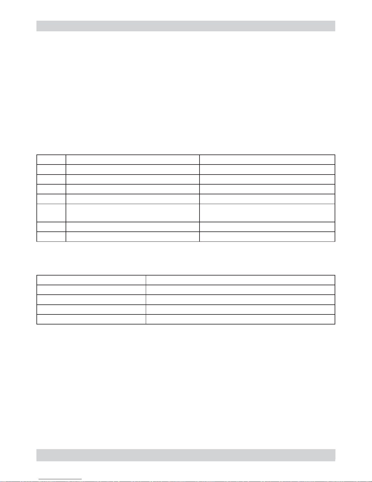
1.2 Tools and equipment required
Besides standard equipment, the following tools are required:
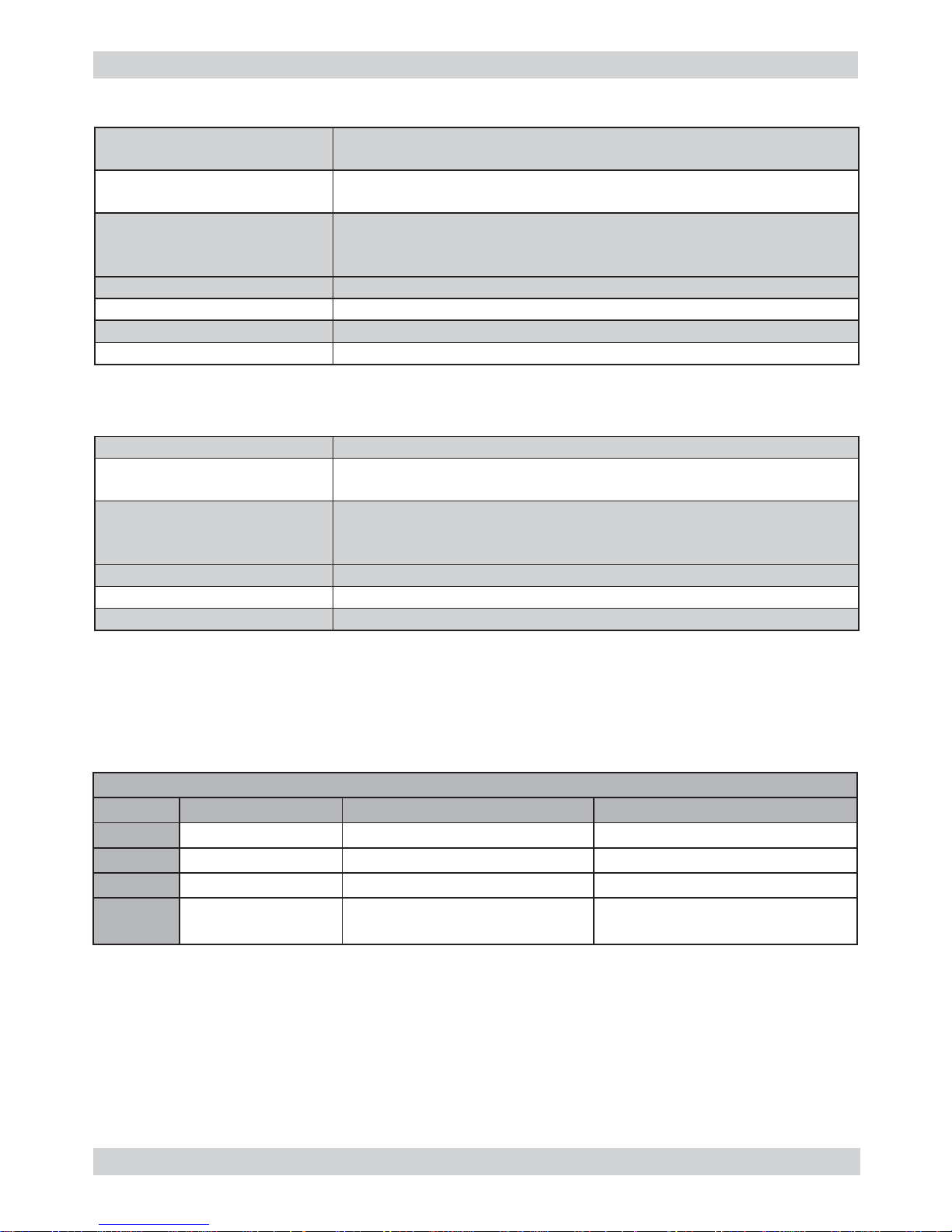
Qty. Description Notes
1 Screwdriver
1 Pliers for Oetiker clamps
1 AC - DC - Vdc tester
1 Digital thermometer Scale Limit > 150°C
1 SSC (Saeco Service Center) Programmer
(for programming and diagnosis mode)
1 Allen wrench
1 Hexagonal spanner
1.3 Material
Description Notes
Thermal grease Thermal resistance > 200°C
Descaler Saeco descaler
Degreaser Personal choice
Silicone grease Safe to use with food
1.4 Safety warnings
It is recommended to consult this Service manual of the machine before implementing any operation.
Comply with all applicable standards relating to the repair of household appliances.
Always disconnect the power plug from the mains before beginning repairs on the machine.
Simply turning off the main switch is not suffi ciently safe to prevent electrical discharges.
This household appliance is rated as insulation class I.
On completion of the repairs, insulation and dielectric rigidity tests must be performed.
01
Page 6
MANUAL MACHINES 01 INTRODUCTION
SAECO Page / 06
02
Components Assembly use Single components available
COFFEE
GRINDER
Only for OOW repairs
YES, to consult the specifi c exploded-view of the
machine or of the Coffee Grinder on website
BREWING
UNIT
Only for OOW repairs
YES, to consult the specifi c exploded-view of the
machine or of the Brewing unit on website
BOILER Only for OOW repairs
YES, to consult the specifi c exploded-view of the
machine on website
GEAR
MOTOR
Only for OOW repairs
YES, to consult the specifi c exploded-view of the
machine on website
FILTER
HOLDER
Only for OOW repairs
YES, to consult the specifi c exploded-view of the
machine on website
MILK
CARAFE
Only for OOW repairs
YES, to consult the specifi c exploded-view of the
machine on website
THERMAL
CARAFE
Only for OOW repairs
YES, to consult the specifi c exploded-view of the
Thermal Carafe on website
MILK ISLAND Only for OOW repairs
YES, to consult the specifi c exploded-view of the
Milk Island on website
1.5 Service POLICY grid as used for coffee machine
List of principal assembly present in all our coffee machines
For IN WARRANTY repairs is mandatory to use the single components (not the assembly) avai-
lable in the exploded views of the coffee machines or of the specifi c components. If you fi nd the
information “SEE THE EXPLODED VIEW E........” in the assembly description fi eld, it means that
the single components of the assembly are available in the other pages of the exploded view. It’s
possible to use the assembly only if there is a specifi c Symptom Cure that include this possibility
or when the single components are not available for the order.
Page 7
MANUAL MACHINES 01 INTRODUCTION
SAECO Page / 06
03
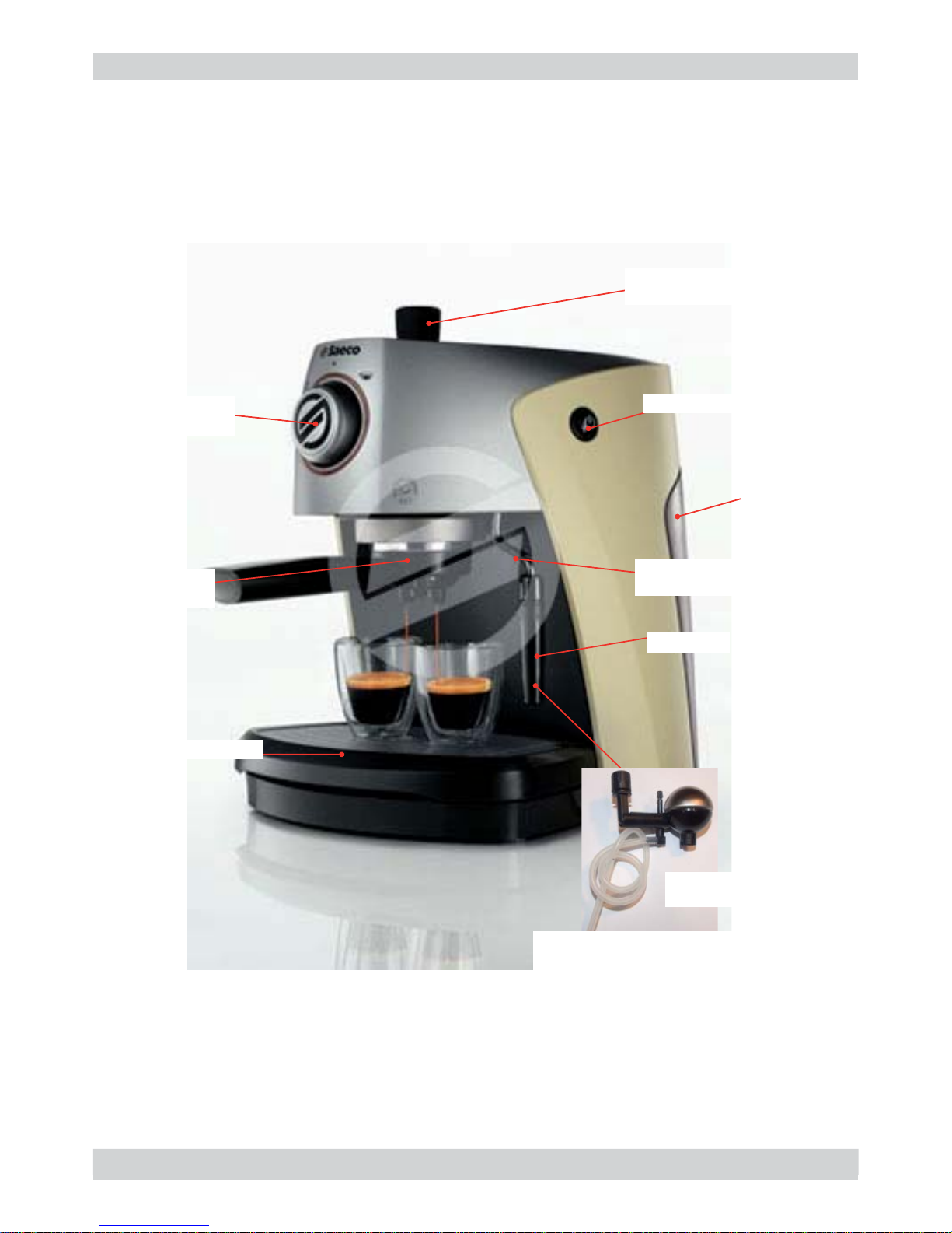
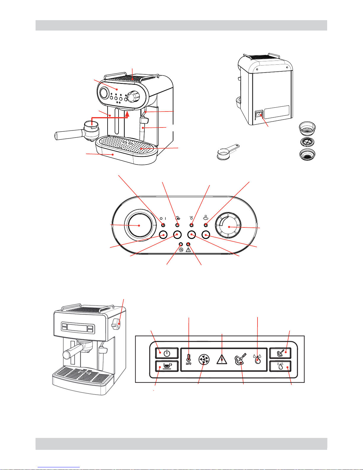
1.6.1 External machine parts in manual machine
Water tank
ON/OFF switch
Hot water/steam
dispensing pipe
Hot water/steam
dispensing knob
Nozzle
Drip tray+grille
Pressurised
fi lter holder
Selection
knob
Some machines have the spherical
cappuccino maker instead of the
nozzle
Spherical
Cappuccino maker
Page 8
MANUAL MACHINES 01 INTRODUCTION
SAECO Page / 06
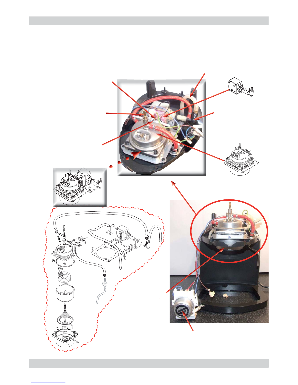
1.6.2 Internal machine parts in manual machine
04
Boiler assembly
Pump assembly
Overpressure
valve
Hot water/Steam
opening - closing
knob rod
Thermal protector
Overpressure
relief valve
Thermostats
Selection knob
Filter holder ring
Page 9
MANUAL MACHINES 01 INTRODUCTION
SAECO Page / 06
05
1.7.1 External machine parts in Estrosa and Carezza
Control panel
Hot water /steam
dispensing pipe
1/2 cup fi lter
Coffee measure
Power cable
connector
Water temperature
thermometer
Steam button
Rinsing button
Led “Allarm”
Led “Descaling”
On/Off button
Coffee button
Led machine “ON”
Led “Temperature”
Led “Rinsing”
Led “Steam”
Knob
Hot water /steam
Support for cups
Drip-tray
Water
tank
Cappuccinatore
Grille
Filter holder
pressurised
Led
“Descaling”
Led
“Steam”
Led
“Rinsing”
Led
““Alarm”
Led
“Temperature”
Coffee button
Rinsing button
Steam button
ON/OFF button
Knob
Hot water /steam
Page 10
MANUAL MACHINES 01 INTRODUCTION
SAECO Page / 06
BOILER
FLOW SELECTOR
FAUCET
Filter holder
pressurised
Boiler
1.7.2 Internal machine parts in Estrosa and Carezza
Coffee
Hot water/steam
Water
tank
Pump
Boiler
Hot water/steam
Cold water
Diagram hydraulic circuit
06
Page 11

SAECO MANUAL MACHINES
CHAPTER 2
TECHNICAL SPECIFICATIONS
Page 12
MANUAL MACHINES 02 TECHNICAL SPECIFICATIONS
SAECO Page / 02
2.1. Technical specifi cations
Technical specifi cations Estrosa and Carezza
2.2. Descaling frequency
Safety system: 2 one-shot thermostats (127°C and 95°C) 1 thermal protector >
184°C
Coffee heat exchanger
output: Stainless steel
(230/120 V~) 1000 W – for coffee, hot water and steam
dispensing
Pump Ulka Type EP5/S GW approx. 13-15 bar with reciprocating piston
and 120°C cutout 48 W, 230V, 50 Hz, 120V, 60Hz 100V, 50/60 Hz
and Defond A2P03 220-240V 53W
Overpressure valve: Opening at approx. 16-18 bar
Water fi lter: In tank
Flow meter assembly Only in the single versions with the coffee amount setting
Consumption: During the heading phase of 8,2A, during the brewing phase 8,5A
Safety system: 2 one-shot thermostats 190°
Coffee heat exchanger
output: Stainless steel
1900 W 230V – for coffee, hot water and steam dispensing
Pump Ulka Type EP5/S GW approx. 13-15 bar with reciprocating piston
and 120°C cutout 48 W, 230V, 50 Hz, 120V, 60Hz 100V, 50/60 Hz
and Defond A2P03 220-240V 53W
Overpressure valve: Opening at approx. 16-18 bar
Water fi lter: In tank
Consumption: During the heading phase of 8,2A, during the brewing phase 8,5A
01
Descaling frequency
Hardness
Water hardness Without anti-scale fi lter With anti-scale fi lter
1 Soft (up to 7°dH) 240 litres (480,000 pulses) 480 litres (960,000 pulses)
2 Medium (7° - 14°dH) 120 litres (240,000 pulses) 240 litres (480,000 pulses)
3 Hard (15° - 21°dH) 60 litres (120,000 pulses) 120 litres (240,000 pulses)
4 Very hard
(over 21°dH)
30 litres (60,000 pulses) 60 litres (120,000 pulses)
Page 13
MANUAL MACHINES 02 TECHNICAL SPECIFICATIONS
SAECO Page / 02
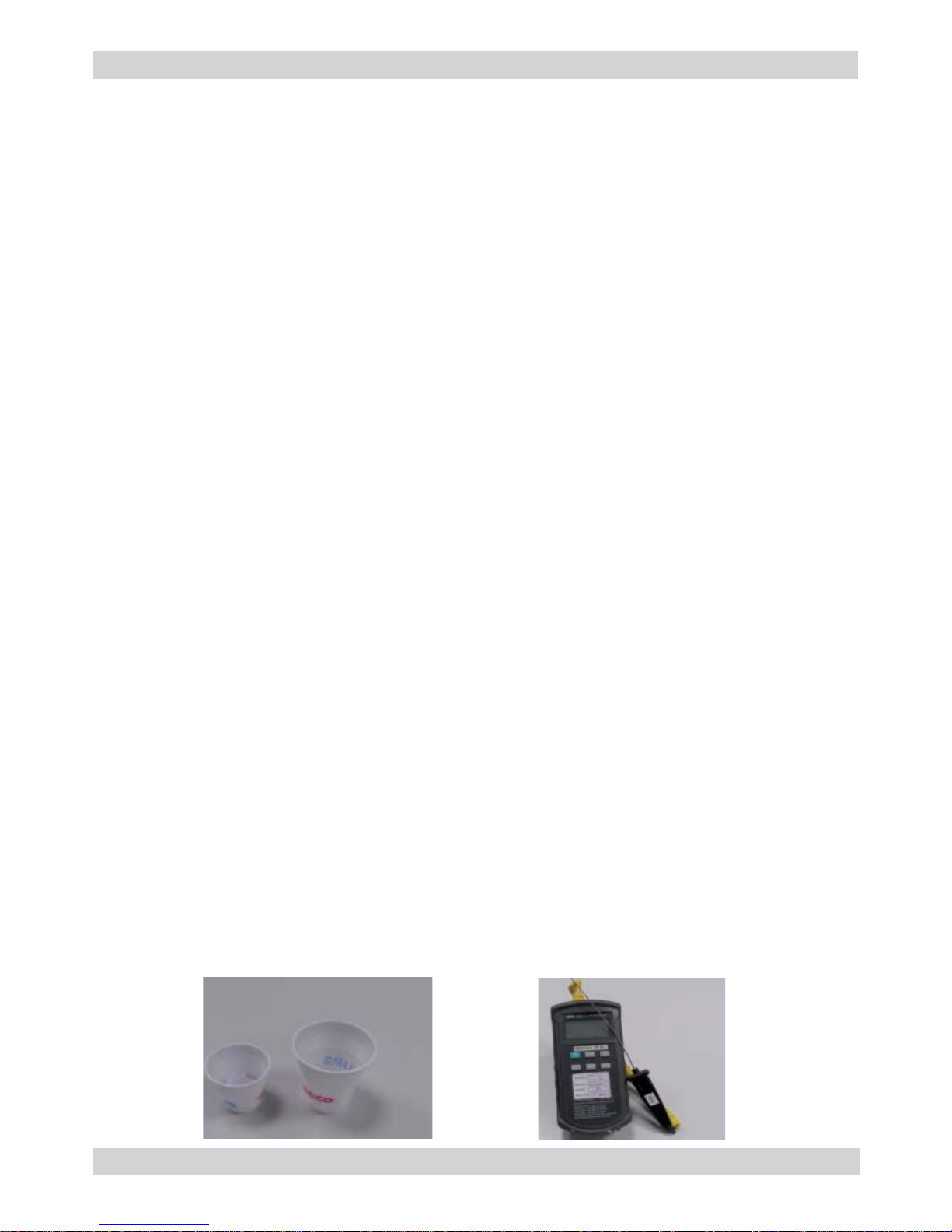
2.3. Specifi cation for the measurement of the coffee products temperature.
The temperature is infl uenced by the fl ow from the dispenser and stratifi cation of temperatures in
the glass. In order to consider these phenomena and to introduce measures that allow comparisons in controlled conditions, below guidelines must be followed:
Conditions:
a) Water temperature in tank: 23°C (+/-2°C).
b) It must be used a plastic cup (see picture N°1).
c) It must be used a thermocouple thermometer (e.g. type K - see picture N°2).
d) The coffee machine is tested without any change of parameters or calibrations, which may
affect the temperature of products, so the measurement of temperature must be done with
machine in default factory setting.
Procedure:
1. The temperature must be measured in the cup, immediately after dispensing. Cup has to be
placed on a non-metal surface using a thermocouple thermometer.
2. The temperature in the cup is measured by immersing the probe of the thermometer up to
touch the bottom.The probe then must be moved in a circular motion for 5/6 rotations. At the
of the rotations, stop in the center of the cup.
3. The highest temperature measured during the rotations is the value we are searching for, and
that must be reported;
4. Test measurement: from end of dispensing to the end of rotations must be completed within 12
seconds.
Limits of acceptability
The acceptance limits are divided by features and products and are the following:
Espresso Coffee Italy Q.ty 25/40 gr.
Temperature of 1st product 69°C ≤ 85°C
Temperature of 2nd product 72°C ≤ 85°C
Coffee Q.ty 70/120 gr.
Temperature of 1st product 69°C ≤ 85°C
Temperature of 2nd product 72°C ≤ 85°C
Picture 1
Picture 2
02
Page 14

SAECO MANUAL MACHINES
CHAPTER 3
USER INSTRUCTIONS
Page 15

MANUAL MACHINES 03 USER INSTRUCTIONS
SAECO Page / 01
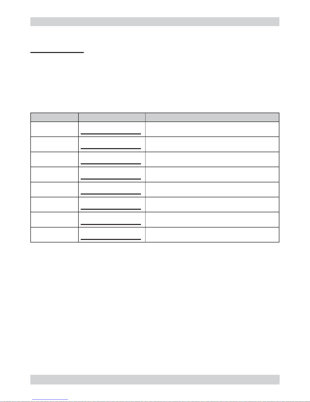
3.1 Operation, cleaning and maintenance
CLEANING AND TECHNICAL ASSISTANCE
A Empty the drip tray As necessary (fl oat)
B Clean the water tank Weekly
C Clean the fi lter holder As necessary
D Clean the casing As necessary
E Descaling cycle If signalled
01
Descaling frequency
Hardness
Water hardness Without anti-scale fi lter With anti-scale fi lter
1 Soft (up to 7°dH) 240 litres 480 litres
2 Medium (7° - 14°dH) 120 litres 240 litres
3 Hard (15° - 21°dH) 60 litres 120 litres
4 Very hard
(over 21°dH)
30 litres 60 litres
Operating the machine
1 Fill the water tank
2
Fill the coffee bean
container
3 Switch on the appliance
4
Press to switch on the
machine
/
5 Heating The heating phase begins, wait for it to fi nish
6 Machine ready The machine is ready to dispense beverages
Page 16

SAECO MANUAL MACHINES
CHAPTER 4
OPERATING LOGIC
Page 17

MANUAL MACHINES 04 OPERATING LOGIC
SAECO Page / 09
WATER TANK
FLOW METER
BOILER
STOPCOCK
THERMOSTATS
HOT WATER/STEAM
DISPENSING PIPE
DISPENSING COFFEE
FILTER HOLDER
PUMP
OVERPRESSURE VALVE
4.1.1 Water circuit
Various types for water circuit
01
- COLD WATER
- HOT WATER/STEAM
- HOT WATER
Coffee
Pump
Boiler
Hot water/steam
Water
tank
P.S.: Only the single coffee machines have a fl ow meter, which can set and save the amount
of dispensed coffee via the control board.
Page 18

MANUAL MACHINES 04 OPERATING LOGIC
SAECO Page / 09
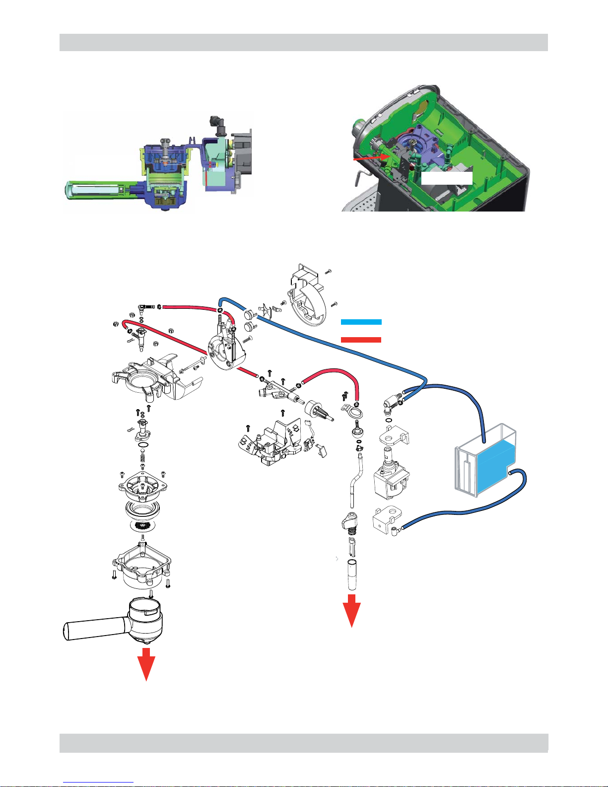
02
4.1.2 Exploded view of a water circuit in Estrosa and Carezza
THERMOSTATS
HOT WATER/STEAM
DISPENSING PIPE
PUMP
BOILER
OVERPRESSURE
VALVE
Page 19

MANUAL MACHINES 04 OPERATING LOGIC
SAECO Page / 09
4.1.3 Exploded view of a water circuit
03
THERMOSTATS
HOT WATER/STEAM
DISPENSING PIPE
OVERPRESSURE
VALVE
PUMP
BOILER
Page 20

MANUAL MACHINES 04 OPERATING LOGIC
SAECO Page / 09
4.1.4 Hydraulic diagram in Estrosa and Carezza
04
Page 21

MANUAL MACHINES 04 OPERATING LOGIC
SAECO Page / 09
4.1.5 Hydraulic diagram
05
Page 22

MANUAL MACHINES 04 OPERATING LOGIC
SAECO Page / 09
4.2.1 Wiring diagram in Estrosa and Carezza
06
Page 23

MANUAL MACHINES 04 OPERATING LOGIC
SAECO Page / 09
07
4.2.2 Wiring diagram
4.2.3 Electrical diagram
Page 24

MANUAL MACHINES 04 OPERATING LOGIC
SAECO Page / 09
4.4 Spherical cappuccino maker and nozzle
08
HOT WATER/STEAM
PIPE FITTING
STEAM
STEAM
HOT WATER/STEAM
PIPE FITTING
AIR FLOW
ADJUSTMENT
NEEDLE
MILK
FROTHED
MILK
STEAM
4.3 Filter holder
Pressurised and mechanical
fi lter holder
Standard
fi lter holder
Page 25

MANUAL MACHINES 04 OPERATING LOGIC
SAECO Page / 09
Anti-scale fi lter
Function:
• Reduced limescale deposits that take longer to form.
• Improved water quality.
• Better taste due to ideal water hardness
Descaling duration / effi ciency:
• - 10° dH
• 60 litres
• 2 months
To obtain a linear characteristic of its effectiveness,
throughout the duration of the descaling process, the
water is split according to the degree of hardness in a
three-phase by-pass (A, B and C).
See small picture.
Bypass
4.6 Anti-scale fi lter
09
4.5 Flow meter
1) upper body
2) fl ow meter
3) magnet
4) O-ring seal
5) lower body
A) Board
The water enters, hits against the blades of the fl ow
meter, causing it to turn.
The magnet passes beneath the board and transmits
the number of revs to it, which in turn transmits it to
the main board
Water inlet
Water outlet
1
4
5
3
A
2
Page 26

SAECO MANUAL MACHINES
CHAPTER 5
TROUBLESHOOTING
Page 27

MANUAL MACHINES 05 TROUBLESHOOTING
SAECO Page / 02
01
5.1 Test Mode in Estrosa and Carezza
ENTER IN TEST MODE:
The entering in Test mode is possible only disconnecting the machine from the main plug,
opening the steam knob and pressing the coffee button and the rinsing button at the
same time, connecting the machine to the main plug and keep pressed the buttons for 3
seconds.
After 3 seconds the Led Alarm and Led Descale turn on and the thermometer (only Gaggia
version)will move to reache the zero to confi rm the entering in TEST MODE.
TEST MODE:
At this point at every button presion will be associate the turning on of one Led and the turning
on of a load for 3 seconds. In this mode it is possible to do the machine steam out.
• ON/OFF button turn on Heater and Led ON for 3 seconds (only in Gaggia machine).
• Coffee button turn on Led coffee and move the Motor for 3 seconds.
• Rinsing button turn on Led Rinsing and Pump. Pressing again the Rinsing button the
pump will turn off.
• Steam button turn on the Led Steam.
STEAM OUT:
• Push contemporarily ON/OFF button and STEAM button will turn on Led ON and the
Led Steam.
• Keep the button pressed for 3 seconds.at the end of this time the 2 led will turn off and
Led Steam starts blinking indicating that the heater is going in steam temperature.
• During the warming up some water will fl ows out from the steam tube.
• When the heater reach the steam temperature no more power is given to the heater.
The Led Steam stop blinking and stays on for 5 seconds to guarantee that the heater is
empty of water.
• At the end of the 5 seconds the Led Steam turn off to allow the user to test the next ma
chine.
• At the end of this action the machine is empty and at the fi rst power on, the circuit rechar
ge is needed.
EXIT FROM TEST MODE:
From the test mode is possible to exit only disconnecting the machine from the main plug.
Page 28

MANUAL MACHINES 05 TROUBLESHOOTING
SAECO Page / 02
02
FAULT POSSIBLE CAUSES SOLUTION
The machine does not
switch on
No power supply Check the electrical circuit
The machine does not warm
up
The thermostats have intervened
The power supply does not reach
the boiler
Replace the thermostats (if of the
One shot type)
If they are manual, reset them
If they are automatic, they are
reset automatically
Check the electrical connections
The pump is very noisy
There is no water in the tank
The pump has disengaged from
the supports
The silicone pipe that carries the
water from the tank to the pump is
pinched or blocked
Fill the tank
Insert the pump into the supports
once again
Check the water circuit
The coffee is too cold
The fi lter holder is not inserted for
the pre-heating process
The cups are cold
Run hot water through the fi lter
holder
Pre-heat the cups with hot water
The milk does not froth
The milk is not suitable (powdered
or skimmed milk)
Dirty nozzle or Cappuccino maker
Use whole milk
Carefully clean the nozzle or the
cappuccino maker with water
The coffee flows too quickly
and does not form the cream
Little coffee in the filter holder
Grinding level too coarse
There is a missing component in
the filter holder
Increase the quantity
Use a different mixture
Verify that all the components are
in place and installed correctly
The coffee does not flow or
it flows in drops
Grinding level too fi ne
The coffee is pressed too much in
the fi lter holder
Too much coffee in the filter holder
Blocked water channels
Blocked filter in the filter holder
Use a different mixture
Agitate the coffee
Reduce the amount of coffee
Descale the machine
Carefully clean the fi lter
The coffee does not flow from
the edges
The fi lter holder has been
inserted incorrectly into the coffee
dispensing unit
The upper border of the fi lter
holder is dirty
The seal of the boiler is dirty or
worn
Too much coffee in the fi lter holder
Insert the fi lter holder correctly
Clean the edges of the fi lter holder
Clean or replace the seal
Reduce the amount of coffee
P.S.: Refi ll the water circuit when the machine is fi rst used as well as when the water in the tank
fi nishes.
5.2 Causes and solutions
Page 29

SAECO MANUAL MACHINES
CHAPTER 6
STANDARD INSPECTIONS
Page 30

MANUAL MACHINES 06 STANDARD INSPECTIONS
SAECO Page / 02
Action
1 Visual inspection (damage during transport)
2 Machine data check (plate)
3 Functional check / problem analysis
4 Opening the machine
5 Visual inspection
6 Functional tests
7 Repairing the faults encountered
8 Checking any modifi cations (view info, etc.)
9 Service activities in accordance with the operating schedule
10 Internal cleaning
11 Functional test with the machine open
12 Assembly
13 Final inspection test
14 Draining the circuit (in winter)
15 External cleaning
16 Insulation test HG 701 (dielectric)
17 Documentation
S Replacement P Cleaning
ES Visual inspection TR Noise test
D Descaling cycle R Adjustment
CF Functional check
Component Action Support/tool
Water fi lter P/S/CF
Water tank lip seal S/CF
Pipes, fi ttings and Oetiker clamps ES/CF
Hot water/steam circuit pump ES/TR/CF
Water circuit D/CF Saeco descaler
Wiring ES/CF
6.2. Service schedule
6.1. Repair schedule
01
Page 31

MANUAL MACHINES 06 STANDARD INSPECTIONS
SAECO Page / 02
Test Procedure
Support/
tool
Standard Tolerance
Coffee
2-3 Coffees for
adjustment purposes
Measuring
beaker
Noise Standard
Amount of
cream
Blow into the cup until
the cream separates
The cream should
come together
again completely
Cream colour Hazel brown
Hot water Dispense water
Steam Dispense steam
6.3. Final inspection
02
Page 32

SAECO MANUAL MACHINES
CHAPTER 7
DISASSEMBLY
Page 33

MANUAL MACHINES 07 DISASSEMBLY
SAECO Page / 08
7.1.1. Outer elements
Upper cover
RIGHT and LEFT side covers
Remove the water tank, the water drip tray, the
grille and the steam knob.
Loosen the screws as shown on the front
and rear part of the machine
Lift the cover and loosen the screws as shown
Remove the side covers
by lifting them upwards
LEFT side cover
(note the hooks
of the cover)
RIGHT side cover. Remove the connection of the
on/off switch from the cover
01
RIGHT
Page 34

MANUAL MACHINES 07 DISASSEMBLY
SAECO Page / 08
02
Remove the knob by
pulling it outwards
Remove the electrical connections
and the two bright indicators
Loosen the overpressure valve
Remove the pump from the supports
Remove the water connections and loosen the screws as shown
Loosen the screws as shown
to remove the rotating switch
7.1.2 Controls support
7.1.3 Boiler support
7.1.4 Pump
Page 35

MANUAL MACHINES 07 DISASSEMBLY
SAECO Page / 08
03
Loosen the screw as shown
Loosen the screws as shown
Loosen the screw as shown
Loosen the
screw of the
valve holder
Check the condition of the
shower, valve holder screw,
channels (holes not blocked)
and verify there is no limescale
on any of the parts
Shower
Loosen the screws as shown
Check the internal condition of the boiler
(limescale, any breakages, condition of the
O-ring seal, etc.)
When putting back the thermostats,
always apply conductive paste for the
thermostat to adhere perfectly to the
boiler
7.1.8 Steam pipe
7.1.5 Boiler thermostats
7.1.6 Boiler
7.1.7 Shower and valve
Page 36

MANUAL MACHINES 07 DISASSEMBLY
SAECO Page / 08
04
7.2.1 Outer elements Carezza / Estrosa
Remove the water tank, the water drip
tray, the grille, the steam knob and pannarello.
steam knob
pannarello
water tank
water drip tray
and grille
Upper cover
LEFT and RIGHT side covers
Loosen the screws as shown on the rear part of the
machine and lift the cover
Remove the posterior
cover lifting it upwards
Loosen the screws as shown
Remove the covers as in the pictures
Pump
Page 37

MANUAL MACHINES 07 DISASSEMBLY
SAECO Page / 08
Loosen the screws
Loosen the screws
Loosen the screws
Loosen the screws to remove the steam pipe
Remove the pump from the supports as the picture
Remove the water and electric connections
Remove the water and
electric connections
Remove the water connections
7.2.2 Pump Esrosa/Carezza
7.2.3 Boiler support assembly Esrosa/Carezza
7.2.4 Steam knob Esrosa/Carezza
7.2.5 Steam pipe Esrosa/Carezza
05
Page 38

MANUAL MACHINES 07 DISASSEMBLY
SAECO Page / 08
7.2.6 CPU/power card Estrosa/Carezza
7.2.7 Keyboard card Estrosa/Carezza
Estrosa
Carezza
Loosen the screws as shown
Loosen the screws as shown
Loosen the screws as shown
Loosen the screws, the electric connection and remove front panel as
shown
Loosen the screws, the electric
connection and remove front
panel as shown
Remove the knob
Hot
water /steam
Remove the electric connections
06
Page 39

MANUAL MACHINES 07 DISASSEMBLY
SAECO Page / 08
7.2.8 Filterholder locking ring Estrosa/Carezza
Loosen the screws
Loosen the bolt
Remove the cover pulling
it down
Remove the water
connections
07
Page 40

MANUAL MACHINES 07 DISASSEMBLY
SAECO Page / 08
1) Boiler connection
2) Other connections
Replacing the pipes
1) Use a suitable pair of pliers to
remove the clamp (as shown in the
picture)
2) Tighten the clamp as shown in the
pictures
7.3 Un/installing Oetiker clamps
1
1
2
2
08
Page 41

SAECO MANUAL MACHINES
CHAPTER 8
NOTES
Page 42

MANUAL MACHINES 08 NOTES
SAECO Page / 01
01
 Loading...