

Saeco Atlante 500, Atlante 700 Use And Maintenance Manual
Vending Machine
UK
WARNING: This instruction manual is intended exclusively for specialized personnel.
USE AND MAINTENANCE
English
2
MAIN PARTS
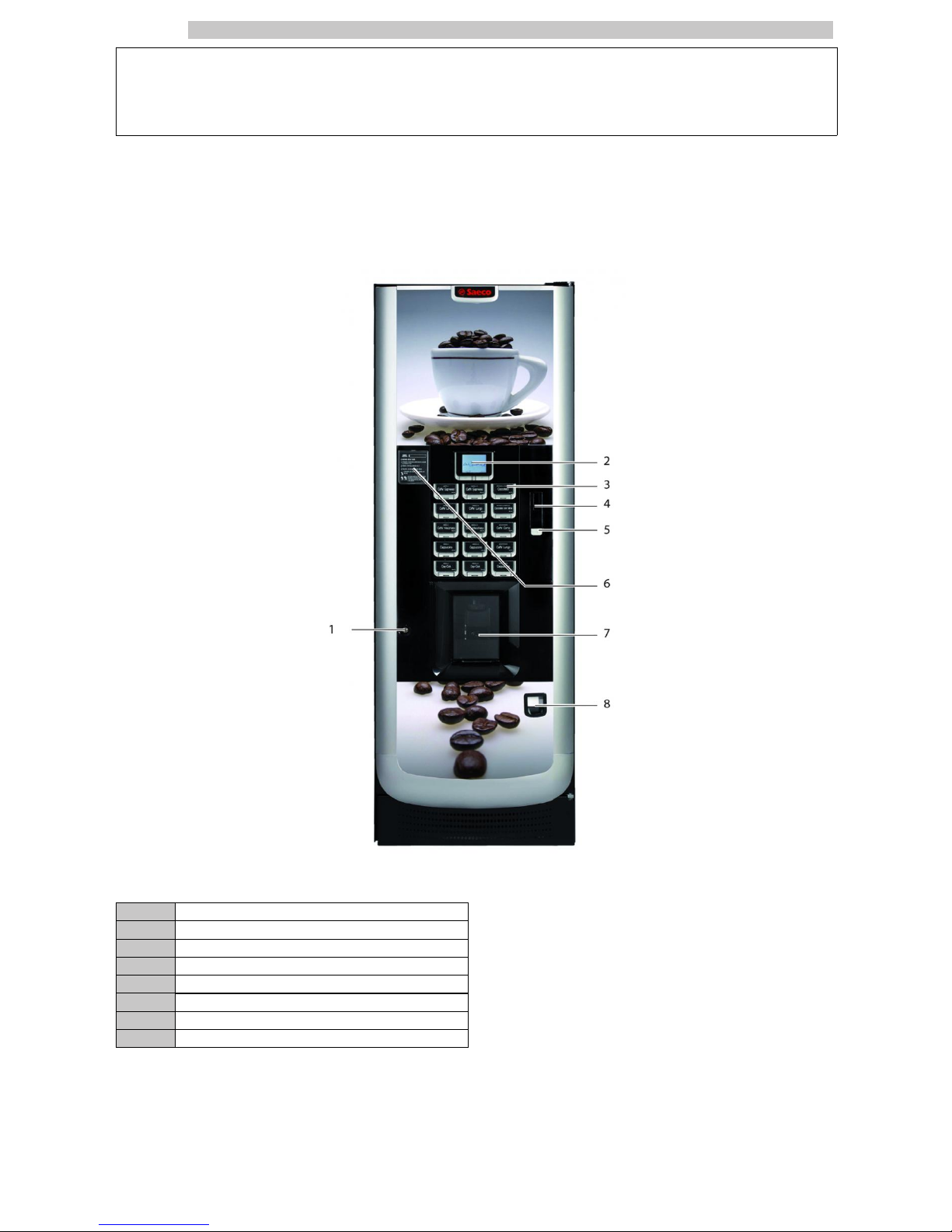
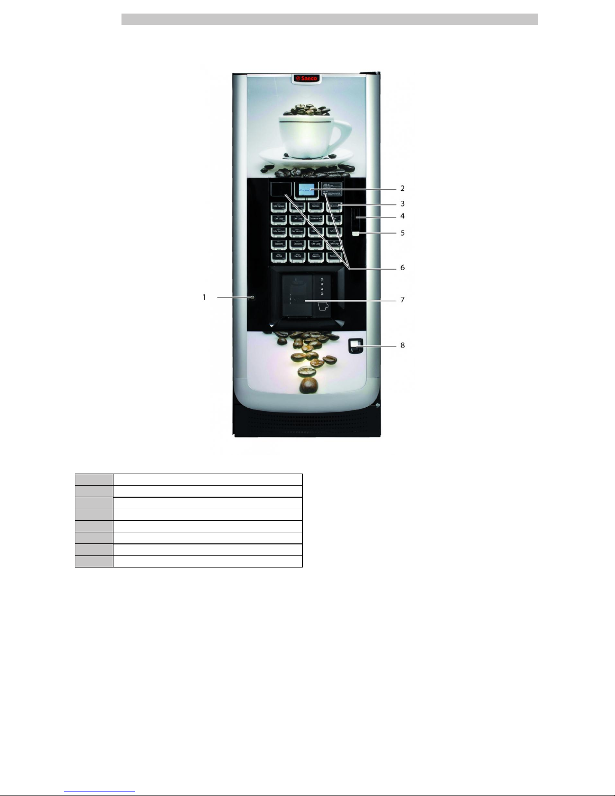
ATLANTE 500 MAIN PARTS
1 Door lock
2 Display
3 Product keypad
4 Coin slot
5 Coin return button
6 Instruction plate
7 Dispensing outlet door
8 Coin return slot
English
3
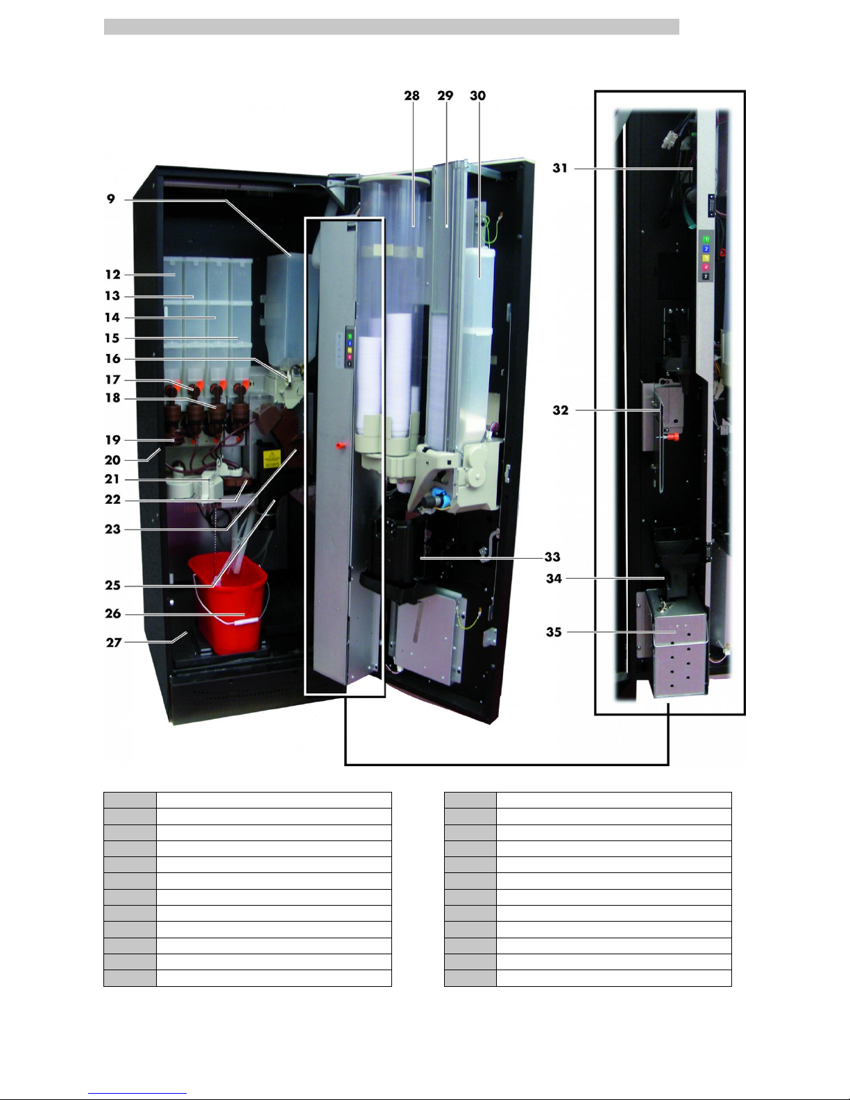
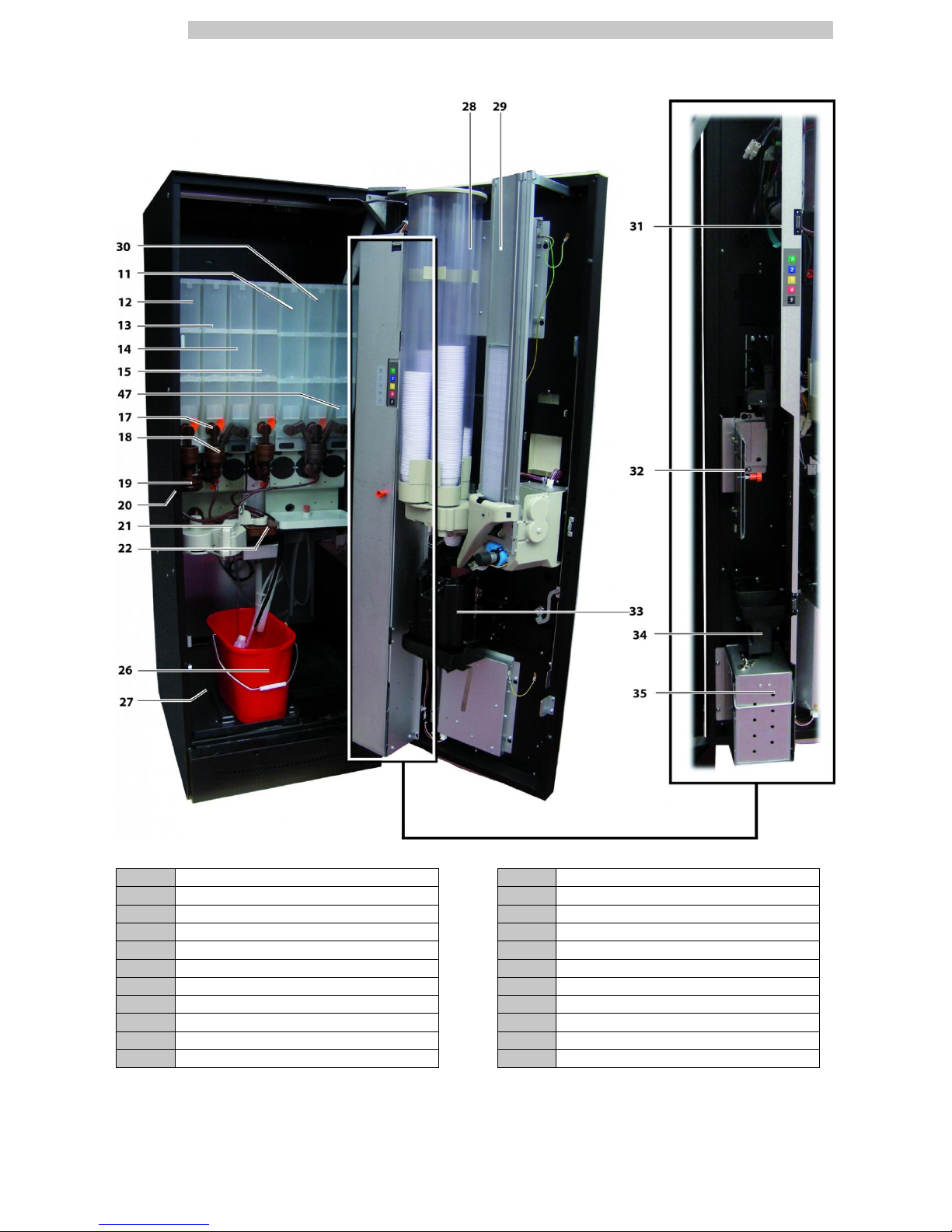
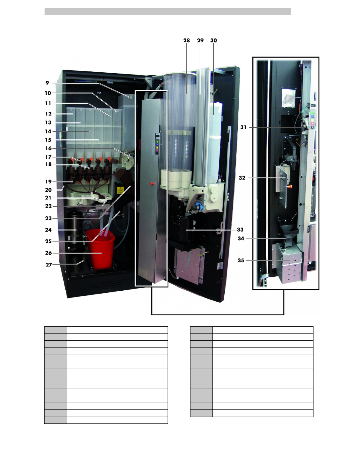
ATLANTE 500 1 GRINDER VERSION MAIN PARTS
9 Coffee bean hopper C 23 Coffee Group
12 Container 1 (instant products) 25 Coffee ground channel
13 Container 2 (instant products) 26 Fluid discharge tank
14 Container 3 (instant products) 27 Collecting tray
15 Container 4 (instant products) 28 Cup dispenser
16 Coffee grinder 29 Stirrer dispenser
17 Instants opening 30 Sugar container
18 Mixer 31 CPU card
19 Spiral mixer 32 Change-giving coiner support
20 Safety switch 33 Dispensing outlet
21 Dispensing arm 34 Coin return duct
22 Drip Tray 35 Coin box set
English
4
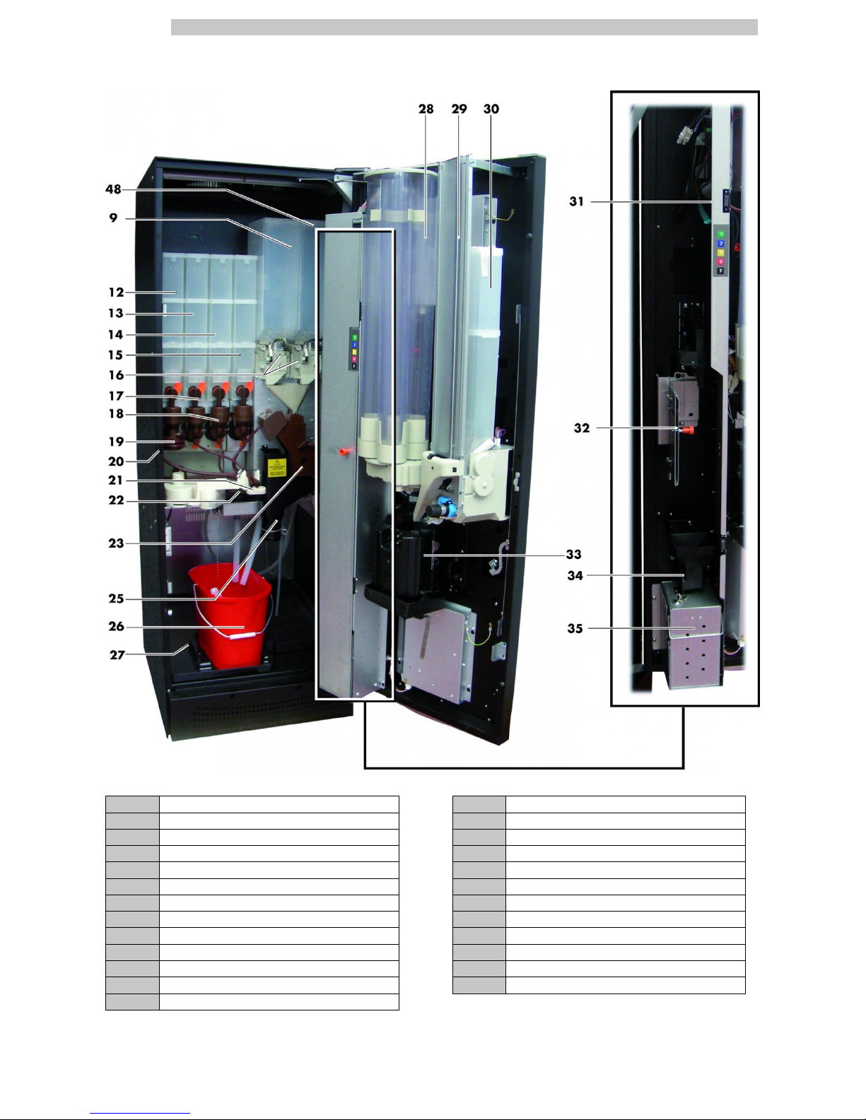
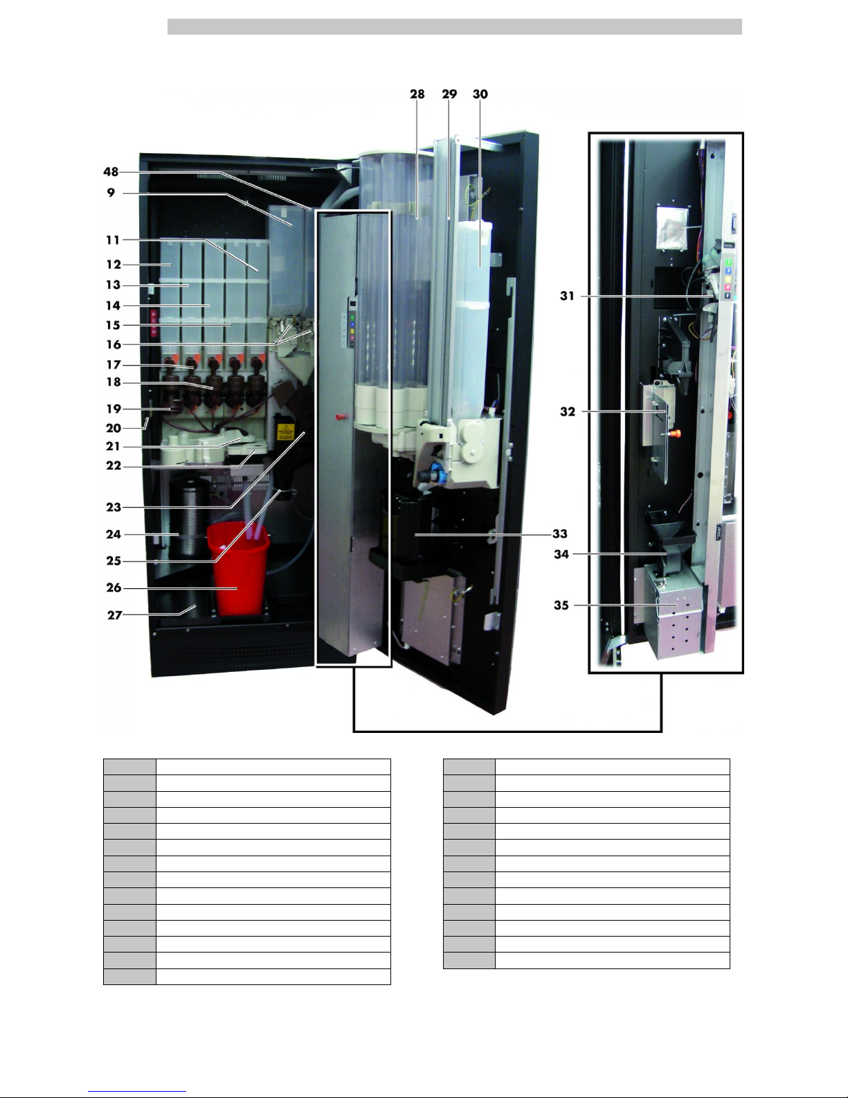
ATLANTE 500 2 GRINDER VERSION MAIN PARTS
9 Coffee bean hopper C 25 Coffee ground channel
12 Container 1 (instant products) 26 Fluid discharge tank
13 Container 2 (instant products) 27 Collecting tray
14 Container 3 (instant products) 28 Cup dispenser
15 Container 4 (instant products) 29 Stirrer dispenser
16 Coffee grinder 30 Sugar container
17 Instants opening 31 CPU card
18 Mixer 32 Change-giving coiner support
19 Spiral mixer 33 Dispensing outlet
20 Safety switch 34 Coin return duct
21 Dispensing arm 35 Coin box set
22 Drip Tray 48 Coffee bean hopper K
23 Coffee Group
English
5
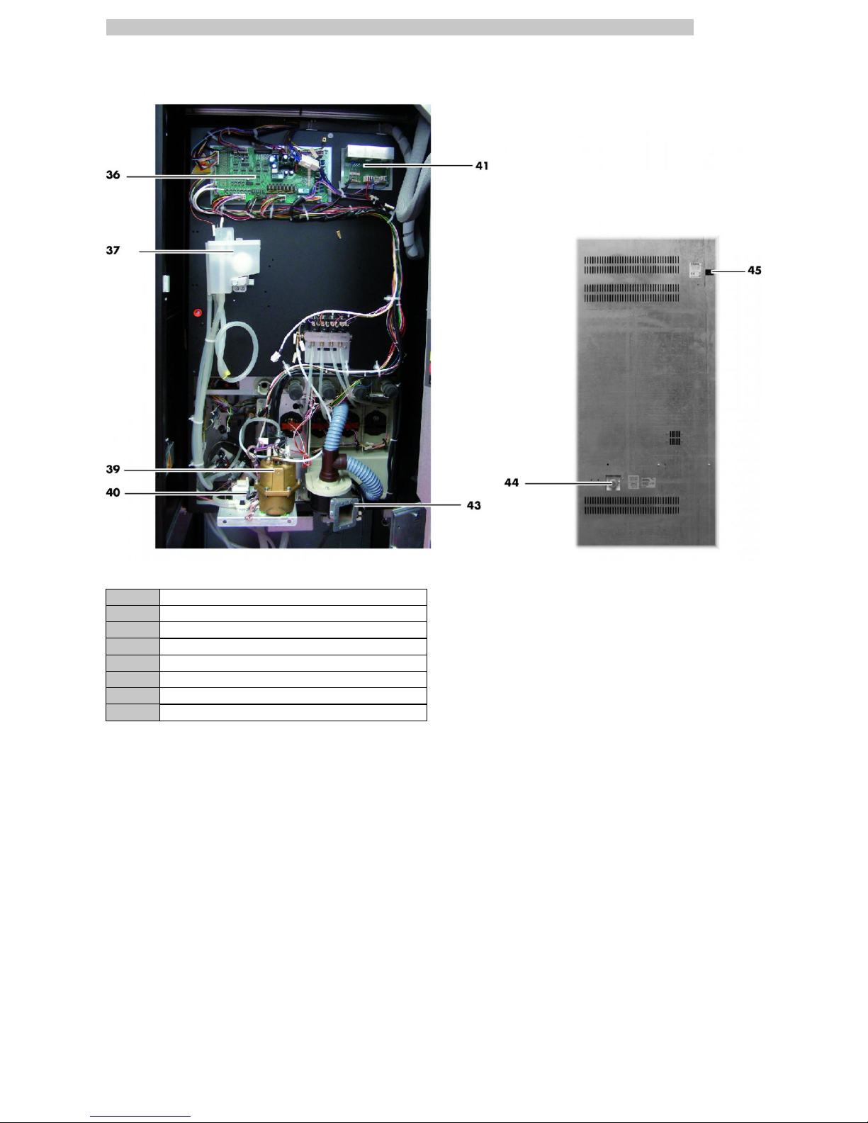
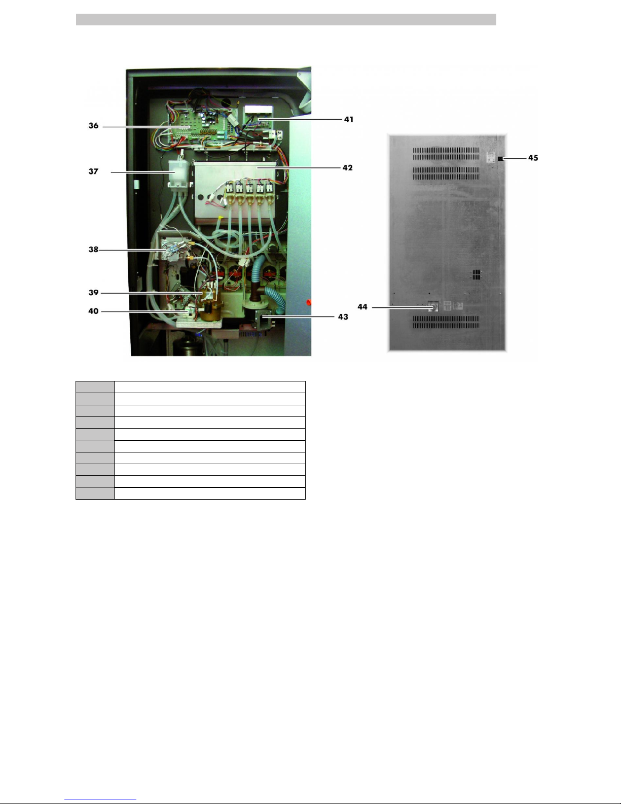
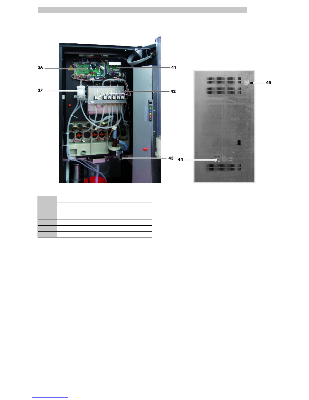
ATLANTE 500 1 & 2 GRINDER VERSION MAIN PARTS
36 Power Board
37 Air break device
39 Coffee boiler
40 Pump
41 Triac board
43 Suction unit
44 Water connection coupling
45 Power cord socket
English
6
ATLANTE 500 INSTANT VERSION MAIN PARTS
11 Container 5 (instant products) 26 Fluid discharge tank
12 Container 1 (instant products) 27 Collecting tray
13 Container 2 (instant products) 28 Cup dispenser
14 Container 3 (instant products) 29 Stirrer dispenser
15 Container 4 (instant products) 30 Sugar container
17 Instants opening 31 CPU card
18 Mixer 32 Change-giving coiner support
19 Spiral mixer 33 Dispensing outlet
20 Safety switch 34 Coin return duct
21 Dispensing arm 35 Coin box set
22 Drip Tray 47 Container 7 (instant products)
English
7
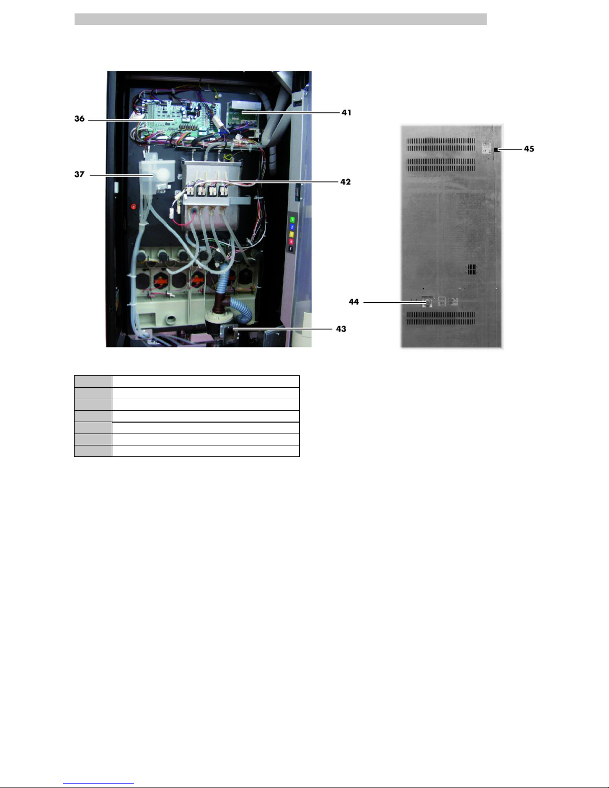
ATLANTE 500 INSTANT VERSION MAIN PARTS
36 Power Board
37 Air break device
41 Triac board
42 Instant product boiler
43 Suction unit
44 Water connection coupling
45 Power cord socket
English
8
ATLANTE 700 MAIN PARTS
1 Door lock
2 Display
3 Product keypad
4 Coin slot
5 Coin return button
6 Instruction plate
7 Dispensing outlet door
8 Coin return slot
English
9
ATLANTE 700 1 GRINDER VERSION MAIN PARTS
9 Coffee bean hopper C 23 Coffee Group
10 Container 6 (instant products) 24 Descaler device
11 Container 5 (instant products) 25 Coffee ground channel
12 Container 1 (instant products) 26 Fluid discharge tank
13 Container 2 (instant products) 27 Collecting tray
14 Container 3 (instant products) 28 Cup dispenser
15 Container 4 (instant products) 29 Stirrer dispenser
16 Coffee grinder 30 Sugar container
17 Instants opening 31 CPU card
18 Mixer 32 Change-giving coiner support
19 Spiral mixer 33 Dispensing outlet
20 Safety switch 34 Coin return duct
21 Dispensing arm 35 Coin box set
22 Drip Tray
English
10
ATLANTE 700 2 GRINDER VERSION MAIN PARTS
9 Coffee bean hopper C 24 Descaler device
11 Container 5 (instant products) 25 Coffee ground channel
12 Container 1 (instant products) 26 Fluid discharge tank
13 Container 2 (instant products) 27 Collecting tray
14 Container 3 (instant products) 28 Cup dispenser
15 Container 4 (instant products) 29 Stirrer dispenser
16 Coffee grinder 30 Sugar container
17 Instants opening 31 CPU card
18 Mixer 32 Change-giving coiner support
19 Spiral mixer 33 Dispensing outlet
20 Safety switch 34 Coin return duct
21 Dispensing arm 35 Coin box set
22 Drip Tray 48 Coffee bean hopper K
23 Coffee Group
English
11
ATLANTE 700 1 & 2 GRINDER VERSION MAIN PARTS
36 Power Board
37 Air break device
38 Steam boiler
39 Coffee boiler
40 Pump
41 Triac board
42 Instant product boiler
43 Suction unit
44 Water connection coupling
45 Power cord socket
English
12
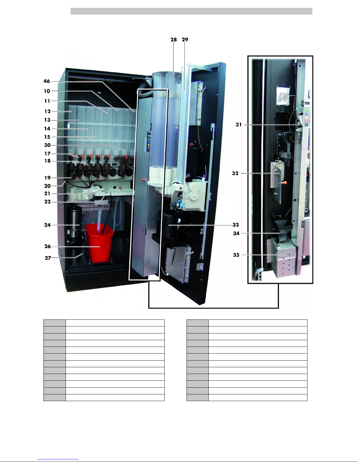
ATLANTE 700 INSTANT VERSION MAIN PARTS
10 Container 6 (instant products) 24 Descaler device
11 Container 5 (instant products) 26 Fluid discharge tank
12 Container 1 (instant products) 27 Collecting tray
13 Container 2 (instant products) 28 Cup dispenser
14 Container 3 (instant products) 29 Stirrer dispenser
15 Container 4 (instant products) 30 Sugar container
17 Instants opening 31 CPU card
18 Mixer 32 Change-giving coiner support
19 Spiral mixer 33 Dispensing outlet
20 Safety switch 34 Coin return duct
21 Dispensing arm 35 Coin box set
22 Drip Tray 46 Container 8 (instant products)
English
13
ATLANTE 700 INSTANT VERSION MAIN PARTS
36 Power Board
37 Air break device
41 Triac board
42 Instant product boiler
43 Suction unit
44 Water connection coupling
45 Power cord socket

English
14
CONTENTS
MAIN PARTS
2
1 INTRODUCTION TO THE MANUAL
15
1.1 INTRODUCTION
15
1.2 SYMBOLS USED
15
2 INFORMATION ON THE VENDING
MACHINE
16
2.1 INFORMATION FOR THE MAINTENANCE
TECHNICIAN
16
2.2 DESCRIPTION AND INTENDED USE
16
2.3 VENDING MACHINE IDENTIFICATION
17
2.4 ATLANTE 500 TECHNICAL SPECIFICATIONS
18
2.5 ATLANTE 700 TECHNICAL SPECIFICATIONS
19
3 SAFETY
20
3.1 INTRODUCTION
20
3.2 GENERAL SAFETY REGULATIONS
20
3.3 OPERATORS' REQUIREMENTS
20
3.4 SAFETY DEVICES
21
3.5 RESIDUAL RISKS
21
4 HANDLING AND STORAGE
22
4.1 UNLOADING AND HANDLING
22
4.2 STORAGE
22
5 INSTALLATION
23
5.1 WARNING
23
5.2 UNPACKING AND POSITIONING
23
5.3 USE OF DIFFERENT-SIZED STIRRERS
24
5.4 LABEL APPLICATION
25
5.5 FITTING THE COFFEE GROUNDS BAG
32
5.6 FITTING THE PAYMENT SYSTEMS
33
5.7 CONNECTION TO WATER MAINS
33
5.8 CONNECTION TO THE ELECTRIC NETWORK
34
6 DESCRIPTION OF CONTROLS FOR ATLANTE
500
35
6.1 DISPLAY
35
6.2 KEYPAD
35
6.3 KEY DESCRIPTION IN STANDARD OPERATION
MODE
35
6.4 CPU CARD KEYS
35
6.5 5-BUTTON KEYPAD
36
7 DESCRIPTION OF CONTROLS FOR ATLANTE
700
37
7.1 DISPLAY
37
7.2 KEYPAD
37
7.3 KEY DESCRIPTION IN STANDARD OPERATION
MODE
37
7.4 CPU CARD KEYS
37
7.5 5-BUTTON KEYPAD
37
8 SUPPLY AND STARTING UP
38
8.1 CONTAINER CONFIGURATION
38
8.2 INSTANT PRODUCT SUPPLY
39
8.3 SUGAR SUPPLY
39
8.4 COFFEE BEAN SUPPLY
39
8.5 DOSE CALIBRATION
39
8.6 COFFEE GRINDING CALIBRATION
40
8.7 SETTING THE WATER CAPACITY FOR INSTANT
PRODUCT SOLENOID VALVES
40
8.8 STIRRER SUPPLY
40
8.9 CUP SUPPLY
41
8.10 FIRST START-UP OF THE VENDING MACHINE
41
8.11 WATER CIRCUIT FILLING
41
8.12 CLEANING THE PARTS IN CONTACT WITH
FOODSTUFFS
42
8.13 USE OF THE VENDING MACHINE
42
9 PROGRAMMING AND MAINTENANCE
MENU
43
9.1 KEY DESCRIPTION OF PROGRAMMING AND
MAINTENANCE PHASES
43
9.2 PROGRAMMING MENU
43
9.3 MAINTENANCE MENU
67
9.4 MACHINE READY / FREE BUTTON
71
9.5 RESET
71
10 OPERATION AND USE
72
10.1 BEVERAGE SELECTION
72
10.2 SNACK PRODUCTS
72
11 CLEANING AND MAINTENANCE
73
11.1 GENERAL NOTES FOR CORRECT OPERATION
73
11.2 CLEANING AND SCHEDULED MAINTENANCE
73
11.3 NON-SCHEDULED MAINTENANCE
80
11.4 PROGRAMMING KEY
81
11.5 SOFTWARE UPDATE
82
12 TROUBLESHOOTING
84
13 STORAGE DISPOSAL
88
13.1 CHANGE OF LOCATION
88
13.2 INACTIVITY AND STORAGE PERIODS
88
14 INSTRUCTIONS FOR END-OF-LIFE
DISPOSAL TREATMENT
89
14.1 INFORMATION FOR THE USER
89
English
1
15
1 INTRODUCTION TO THE MANUAL
1.1 Introduction
This publication is an integral part of the vending
machine and must be read carefully to ensure the
machine is used correctly and in compliance with
essential safety requirements.
This manual contains the technical information
required for the correct use, installation, cleaning, and
maintenance of the vending machine.
Always refer to this publication before carrying out any
operation.
Manufacturer: SAECO Vending S.p.A.
Località Casona, 1066 40041 Gaggio Montano
Bologna, Italy
This publication should be kept carefully, together with
the vending machine throughout its operational life,
even in case of changes of ownership.
If this manual is damaged or lost, a copy may be
requested from the manufacturer or the technical
service by indicating the data contained on the data
plate on the rear side of the vending machine.
All the images in this manual refer to the ATLANTE 700
model.
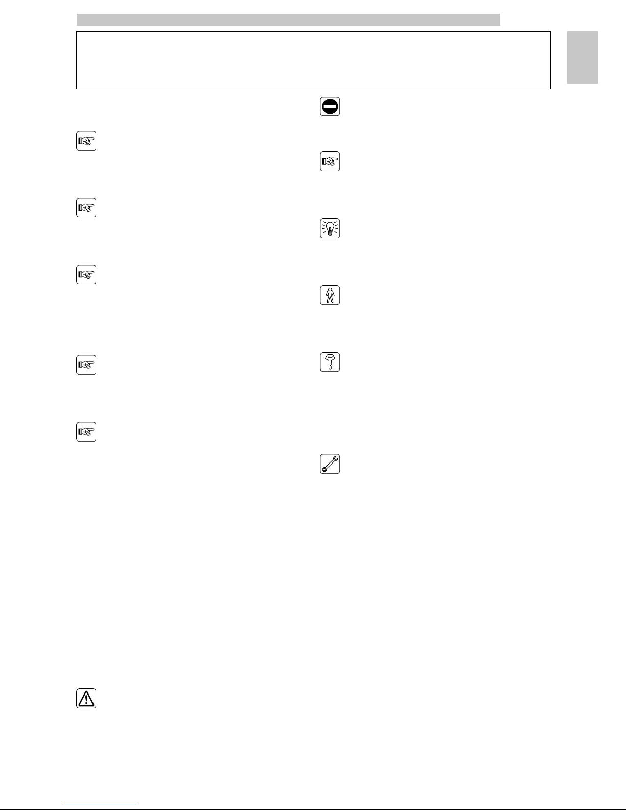
1.2 Symbols used
This publication contains various warnings which indicate
different degrees of danger or skills required.
The symbol is integrated with a message suggesting use
procedures or actions and providing useful information for
the correct operation of the machine.
Warning
Indicates dangerous situations for the users, supply
operators and maintenance technicians dealing either with
the vending machine or the product to be dispensed.
Prohibition notice
It is used to highlight actions/operations not to be
performed.
Important
Indicates the operations for keeping the vending machine
in good working order.
Recommended solutions
Indicates alternative procedures that make the
programming and/or maintenance operations quicker.
User
Indicates the user of the vending machine. This person is
not authorized to carry out any cleaning or maintenance
operation.
Supply operator
Indicates operations to be carried out only by personnel in
charge of supplying and cleaning the vending machine.
Maintenance operations requiring a Maintenance Technician are
not to be performed by the supply operator.
Maintenance Technician
Indicates operations to be carried out by qualified personnel in
charge of maintenance.
The Maintenance Technician is the only person authorized to
keep the MICROSWITCH ENABLING KEY, by which the
security systems can be disabled.
English
2
16
2 INFORMATION ON THE VENDING MACHINE
2.1 Information for the
Maintenance Technician
The vending machine must be installed in a well-lit, dry
area, away from bad weather and dust, on a floor
suitable to support its weight.
To guarantee the correct operation and reliability over
time, the following is recommended:
• ambient temperature: from +1°C to +25°C;
• maximum humidity: 90% (not condensed).
For special installations not covered in this publication,
please contact the dealer or the local importer. If this is
not possible, please contact the Manufacturer directly.
The technical service is available for any explanation or
information regarding the correct operation of the vending
machine and to satisfy any request for spare parts supply
or technical assistance.
The Maintenance Technician must carefully read and
respect the safety warnings contained in this manual so
that every intervention concerning installation, starting up,
use and maintenance will be safely carried out.
It is the Maintenance Technician’s absolute responsibility
to give the keys to access the inside of the vending
machine to another operator (Supply Operator), provided
that the Maintenance Technician bears full responsibility
for all work carried out.
This manual is an integral part of the machine and must be
always read carefully before performing any operation.
2.2 Description and intended use
The vending machine is intended for automatic distribution of
coffee and hot beverages (decaffeinated coffee, cappuccino,
chocolate, etc.) and is programmable for every single type of
dispensing dosage. The instant products must be consumed
immediately, and cannot be preserved for a long time.
Any other use is to be considered improper and therefore
dangerous.
Do not place any product inside the vending machine which
may be dangerous as a result of unsuitable temperatures.
Improper use of the vending machine invalidates all
warranties. The Manufacturer declines any liability for
damage to property or injury to persons.
Improper use also includes:
• any use of the vending machine other than the intended use
and/or according to procedures which are not described in this
publication;
• any intervention on the vending machine which differs from the
instructions given in this publication;
• any alteration of components and/or safety devices without prior
consent of the Manufacturer or carried out by personnel not
authorized for such operations;
• any location of the vending machine not provided in this manual.
English
2
17
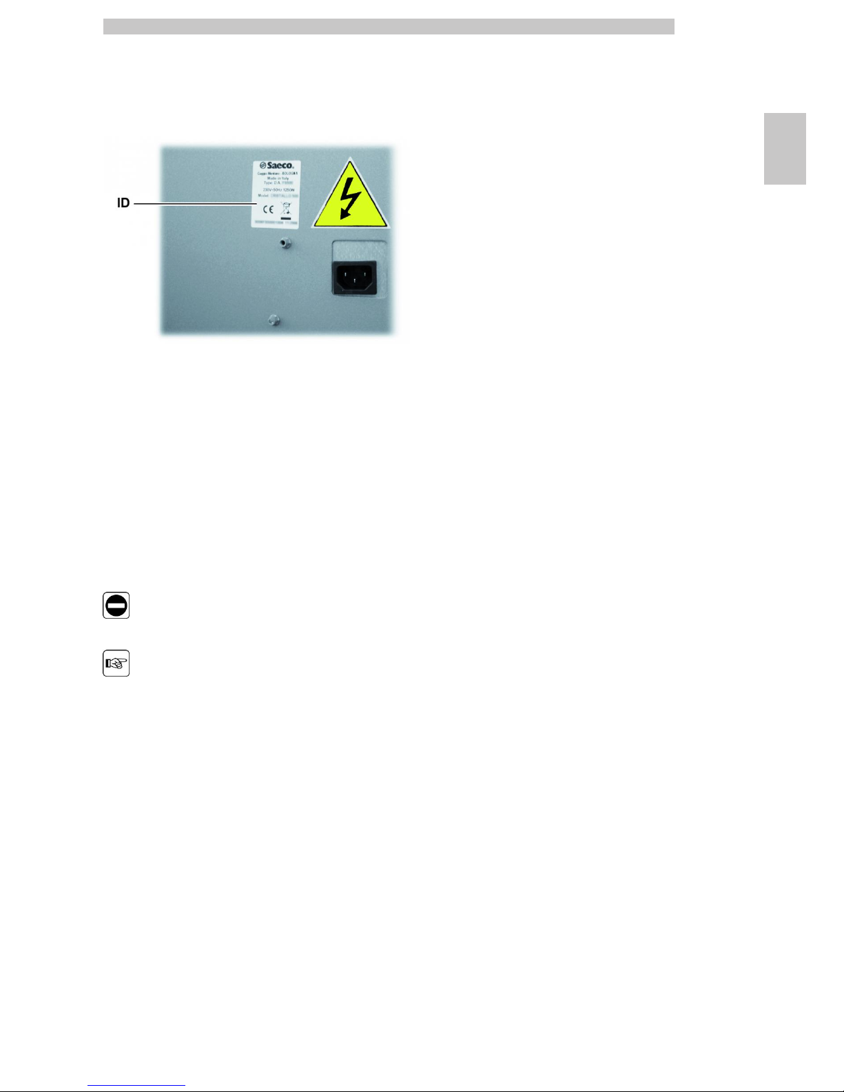
2.3 Vending Machine Identification
The vending machine is identified by the name, model and serial
number which can be found on the relevant data plate.
ID Data plate
The following data can be found on the plate:
• name of Manufacturer;
• marks of compliance;
• model;
• serial number;
• year and month of manufacture;
• supply voltage (V);
• supply frequency (Hz);
• electrical power consumption (W).
It is strictly forbidden to tamper with or modify the
data plate.
When contacting the technical service, always refer to
this plate by indicating the technical data shown on it.
English
2
18
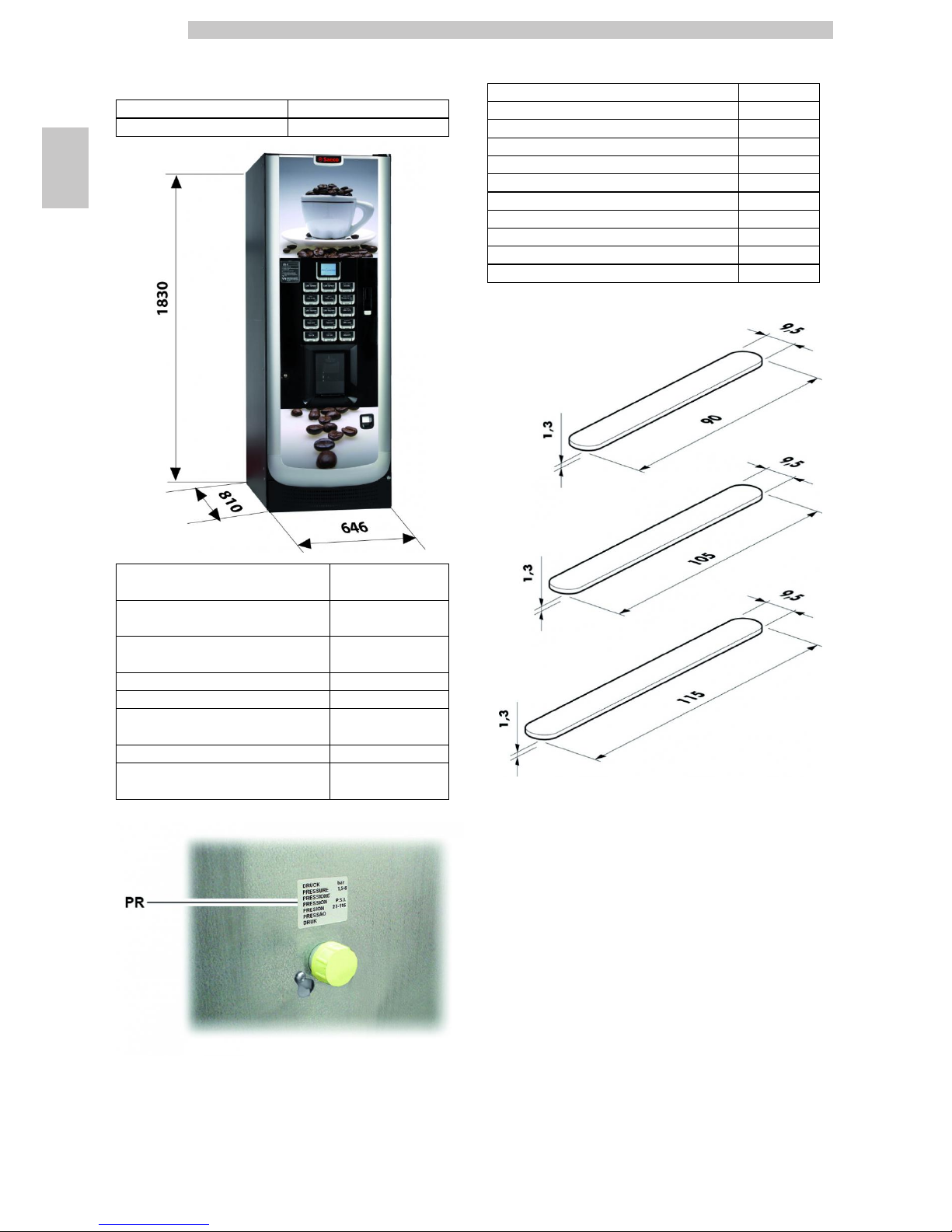
2.4 ATLANTE 500 Technical
Specifications
Dimensions (w x h x d) 646 x 1830 x 810 mm
Weight 162 kg
Power consumption see data plate
Supply voltage see data plate
Electric voltage frequency see data plate
Power cord length 2500 mm
Water mains connection 3/4"
Min. water inlet pressure
0,15 MPA (1,5
bar)
Max. water inlet pressure 0,8 MPA (8 bar)
A-Weighted sound pressure level less than 70 dB
PR
Data plate showing minimum and maximum
water supply pressure
Container capacity
Coffee beans (1 Grinder model) 3,5 kg
Coffee beans (2 Grinders model) 2,6 + 2,6 kg
Freeze-dried coffee (Instant Model) 1,2 kg
Decaffeinated coffee 1 kg
Hot Chocolate 3 kg
Milk 2,5 kg
Lemon tea 3 kg
Barley 1 kg
Sugar 3 kg
Cups N° 550
Stirrers N° 550
Stirrer size
English
2
19
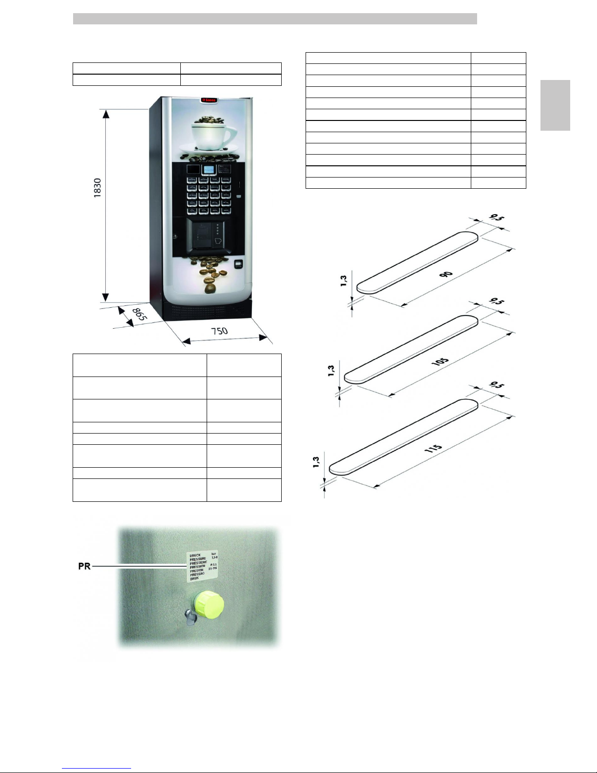
2.5 ATLANTE 700 Technical
Specifications
Dimensions (w x h x d) 750 x 1830 x 865 mm
Weight 184 kg
Power consumption see data plate
Supply voltage see data plate
Electric voltage frequency see data plate
Power cord length 2500 mm
Water mains connection 3/4"
Min. water inlet pressure
0,15 MPA (1,5
bar)
Max. water inlet pressure 0,8 MPA (8 bar)
A-Weighted sound pressure level less than 70 dB
PR
Data plate showing minimum and maximum
water supply pressure
Container capacity
Coffee beans (1 Grinder model) 4,2 kg
Coffee beans (2 Grinders model) 3,5+ 3,5 Kg
Freeze-dried coffee (Instant Model) 1,2 kg
Decaffeinated coffee 1 kg
Hot Chocolate 3 kg
Milk 2,5 kg
Lemon tea 3 kg
Barley 1 kg
Sugar (Espresso version, 1 and 2 grinders) 4,5 kg
Sugar (Instant version) 4 Kg
Cups N° 700
Stirrers N° 550
Stirrer size
English
3
20
3 SAFETY
3.1 Introduction
In compliance with the Low Tension Directive 2006/95/EC
(which replaces the directive 73/23/EEC and following
amendments) and CE Marking Directive 93/68/EEC,
SAECO Vending has drawn up a technical file of the
ATLANTE 500 and ATLANTE 700 vending machine held
at its plants. The following regulations were taken into
account during the design phase:
- EN 55014 - EN 61000-4-4
- EN 6100-3-2 - EN 61000-4-5
- EN 61000-3-3 - EN 61000-4-11
- EN 61000-4-2 - EN 60335-2-75
- EN 61000-4-3 - EN 60335-1
3.2 General safety regulations
It is forbidden to:
• tamper with or disable the safety systems installed on the
vending machine;
• carry out maintenance on the vending machine without
unplugging it first;
• install the vending machine on the outside. It is advisable to place
it in a dry place where the temperature does not drop below
1°C, in order to prevent any possible freezing.
• use the vending machine for purposes other than those indicated
in the sale contract and in this publication;
• connect the appliance to the mains using multi-sockets or
adapters;
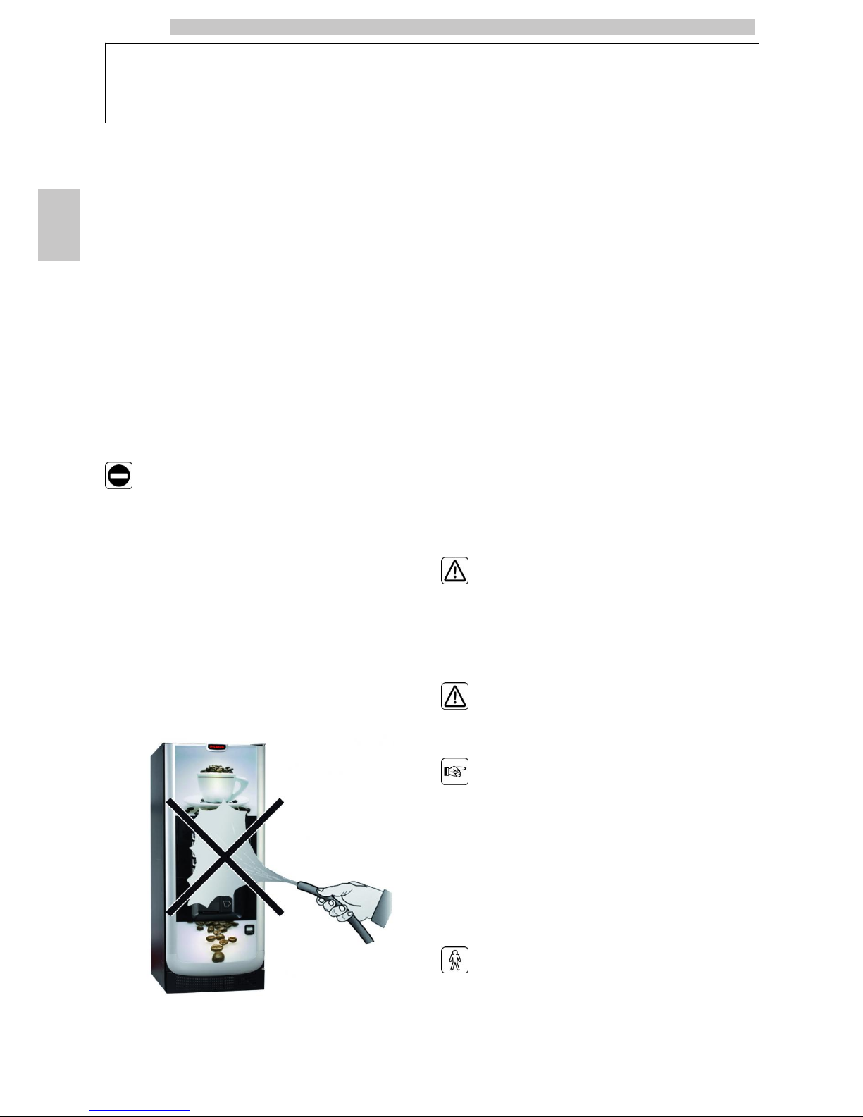
• use water jets to clean the vending machine.
It is compulsory to:
• check the electrical power line for conformity;
• use original spare parts;
• read the instructions contained in this publication and in the
enclosed documents carefully;
• use personal protection devices during installation, testing and
maintenance operations;
• Use a new gasket kit every time you disconnect and then
connect again the machine to the water supply.
Precautions for preventing human errors:
• make the operators aware of safety issues;
• handle the vending machine, either packaged or unpackaged, in
safe conditions;
• have a thorough knowledge of the installation procedures, its
operation and limits;
• dismantle the vending machine in safe conditions, in accordance
with the environmental protection and health and safety laws in
force.
To prevent machining residues from coming into
contact with the beverages, dispense about 0.5 l water
for each dispensing path before definitely starting the
vending machine. The dispensed beverages can be
consumed only after performing this operation.
In case of failure or malfunctioning, please refer only to
the qualified personnel of the technical service.
The Manufacturer declines any liability for any damage
caused to property or injury caused to persons as a
result of failure to observe the safety regulations
described here.
3.3 Operators' requirements
Three operators with different skills are required in order
to guarantee the safety of the vending machine:
User
Access to the internal part of the vending machine is
forbidden to the user.
English
3
21
Supply operator
The Maintenance Technician assigns the safekeeping of the
access key to the Supply operator who is in charge of
product supply, external cleaning, and starting up /
stopping of the vending machine.
The Supply Operator is not authorized to carry out
operations which are indicated as being the duties of
the Maintenance Technician in this publication.
Maintenance Technician
The Maintenance Technician is the only person authorized to intervene
and start programming procedures, and perform adjusting, setting up and
maintenance operations on the vending machine.
Access to the service area is restricted to persons having knowledge
and pratical experience of the appliance, in particular as far as safety
and hygiene are concerned.
3.4 Safety devices
The vending machine is equipped with:
• a safety switch which cuts out the voltage to all the inside
components any time the front door is opened.
• a safety switch located on the dispensing outlet door,
which blocks the nozzle arm cycle whenever the door is
opened.
IS Safety switch
Maintenance Technician
In case of programming or setting up operations only the
Maintenance Technician can intervene by inserting the
relevant key into the safety switch and resetting the
voltage even if the door is open.
This operation, necessary for starting up the vending
machine, disables the safety system.
It must therefore be carried out by qualified personnel
(Maintenance Technician) aware of the risks resulting
from the presence of live or moving components.
3.5 Residual risks
The dispensing outlet is protected by the door interlocked
by the safety switch.
If it is opened during the brewing cycle, mechanical
movement is blocked, but if brewing has already started, it
continues up to the end of the cycle.
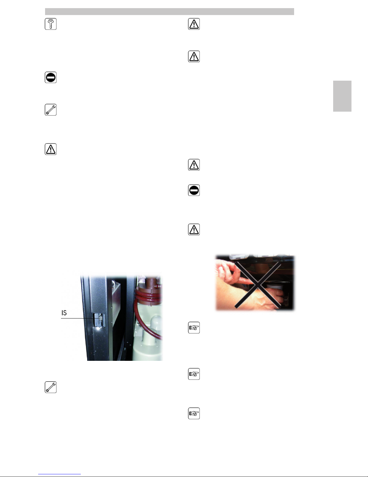
Risk of scalding if hands are placed inside the outlet
during brewing.
It is forbidden to open the door and take out the cup
or put hands inside the outlet during dispensing,
before the brewing cycle is complete.
Before removing the cup from the outlet, please wait
for the message “REMOVE CUP” on display.
If the outlet door is opened during the brewing cycle,
the message “CLOSE SERVICE DOOR” will be
displayed; the nozzle arm stops and will not restart
until the door is closed.
It is not possible to brew further beverages if the
previous cup is not taken out (see the “Dispensing
outlet microswitch” menu item).
Before brewing another beverage, check that the
previous one has been taken out and that the cup
support is empty.
English
4
22
4 HANDLING AND STORAGE
4.1 Unloading and handling
Unloading and handling operations after transportation
must be carried out only by qualified personnel and using
suitable equipment.
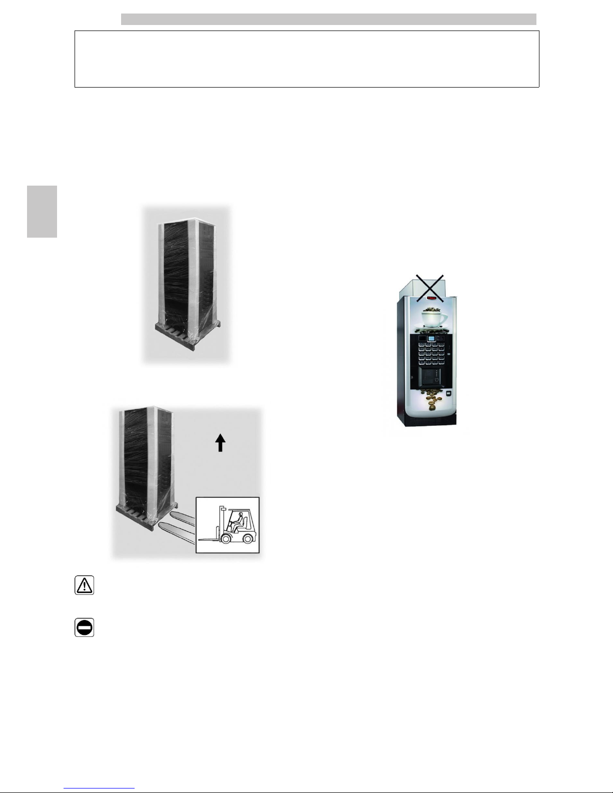
The vending machine is placed on a pallet, protected by a
sack, by a shrink film and four angle bars.
Use a fork-lift to unload the vending machine from the
transport vehicle.
The vending machine must always be kept in the
upright position.
Avoid:
• dragging the vending machine;
• overturning or laying the vending machine flat during
transport and handling;
• shaking the vending machine;
• lifting the vending machine with ropes or cranes;
• leaving the vending machine exposed to the elements, in
humid areas or close to heat sources.
4.2 Storage
If the vending machine is not installed immediately, it
should be stored in a sheltered area, conforming to the
following instructions:
• the packaged vending machine must be stored in a closed,
dry area at a temperature between 1°C and 40°C;
• do not put other appliances or boxes on the vending
machine;
• it is always good practice to protect the vending machine
from any deposits of dust or other material.
English
5
23
5 INSTALLATION
5.1 Warning
The vending machine cannot be installed outdoors;
avoid placing it in areas where the temperature is less
than 1°C or more than 25°C and in particularly dump
or dusty areas.
Before unpacking, check that the installation area complies
with the following specifications:
• the power socket must be located in an easily accessible
area, not more than 1.5 meters away;
• the socket voltage must comply with that on the
identification plate;
• the surface or floor must NOT have a gradient of more
than 2°.
The vending machine must be installed on a flat
surface.
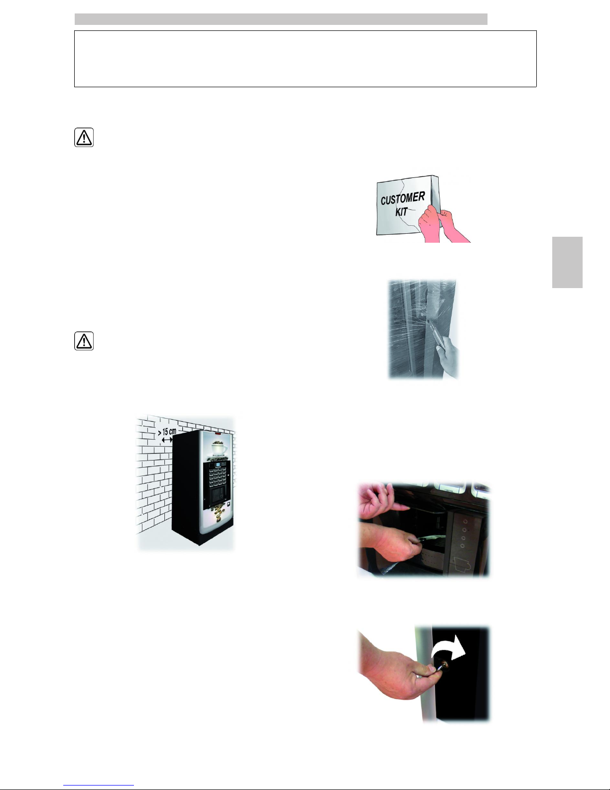
If the vending machine needs to be positioned close to a
wall, it is necessary to leave a space of at least 15 cm
between the back and the wall in order to keep the air
outlet grille free.
5.2 Unpacking and positioning
On receipt of the vending machine make sure that it has
not been damaged during transportation and that package
has not been tampered with or that internal parts have not
been removed.
A bag, called “CUSTOMER KIT”, is supplied with the
vending machine. It contains the following items:
• Instruction booklet
• Power cord
• Door safety microswitch disabling keys (Maintenance
Technician)
• Product labels and prices
• Instruction plate
• Coin box labels.
Remove the transparent protective film and the four angle
bars.
If damage of any kind is found, the courier must be
informed and notice must be given to the importer or the
seller immediately.
If these are not in the purchaser’s country, please contact
the manufacturing company directly.
Take the key from the dispensing outlet.
Insert the key into the lock, turn clockwise and open the
door.
English
5
24
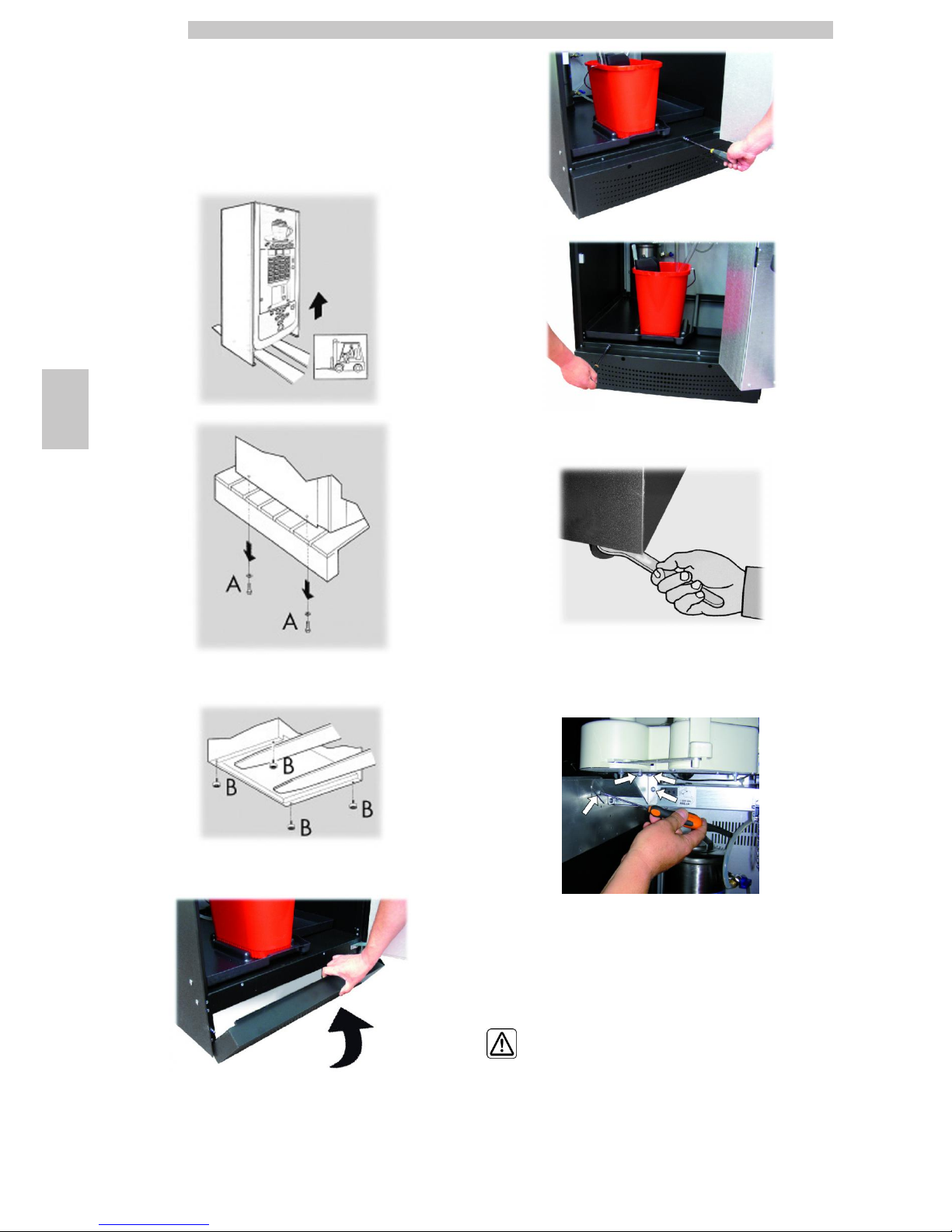
From the discharge tank, take out the accessory packet
containing the following items:
- 4 feet;
- 1 key for the brew group.
Lift the pallet in a way that the four fixing A screws can be
removed.
Screw the four supporting feet B.
Assemble the base by tightening the two screws as shown in the figure.
Adjust the levelling using the relevant feet.
Before operating the machine, unscrew the 4 screws to remove the
central plate support bracket.
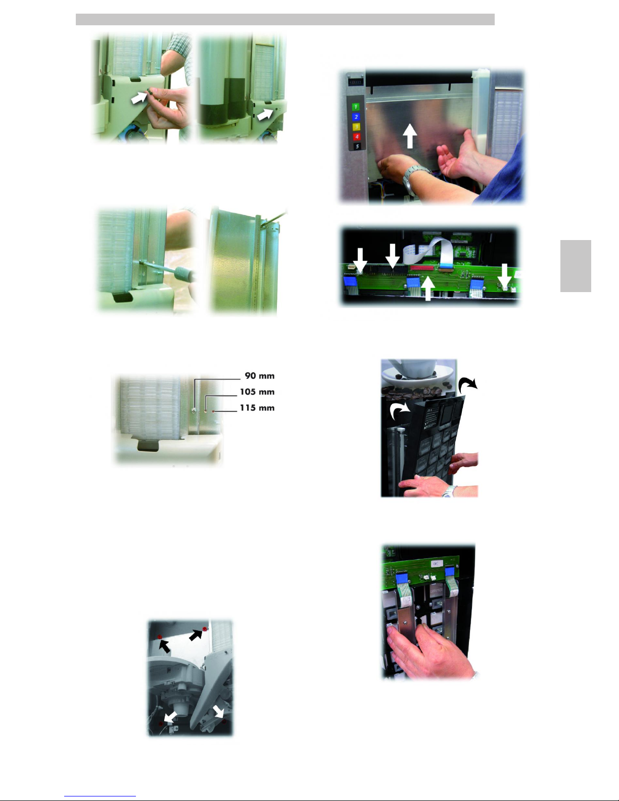
5.3 Use of different-sized stirrers
The vending machine is delivered with the stirrer set
designed for use of 90 mm stirrers.
If 90 mm stirrers are used, make sure that the rubber
pin is inserted in the hole.
English
5
25
To substitute the 90 mm stirrers with those of 105 mm or
115 mm proceed as follows:
• Unfasten the two screws fixing the stirrer guide;
• Move the stirrer guide into the hole corresponding to the
desired dimension and tighten the two screws.
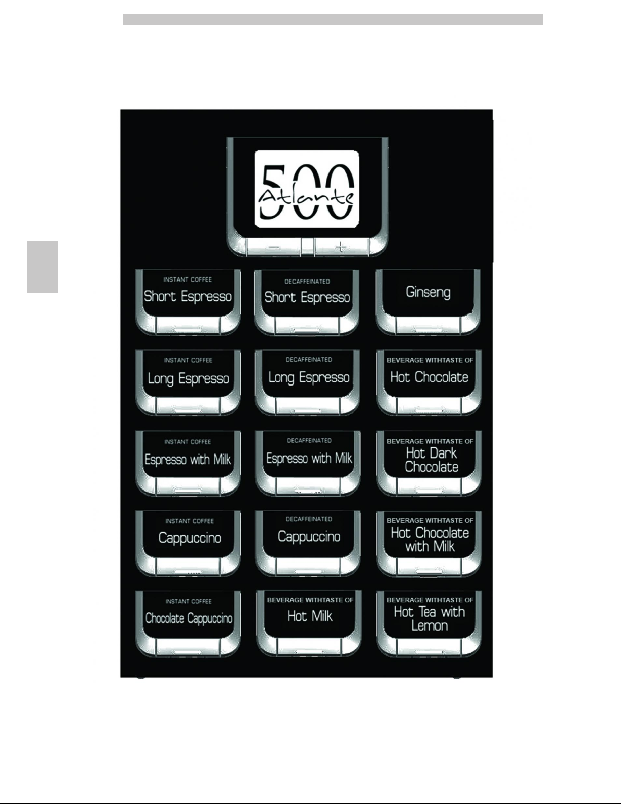
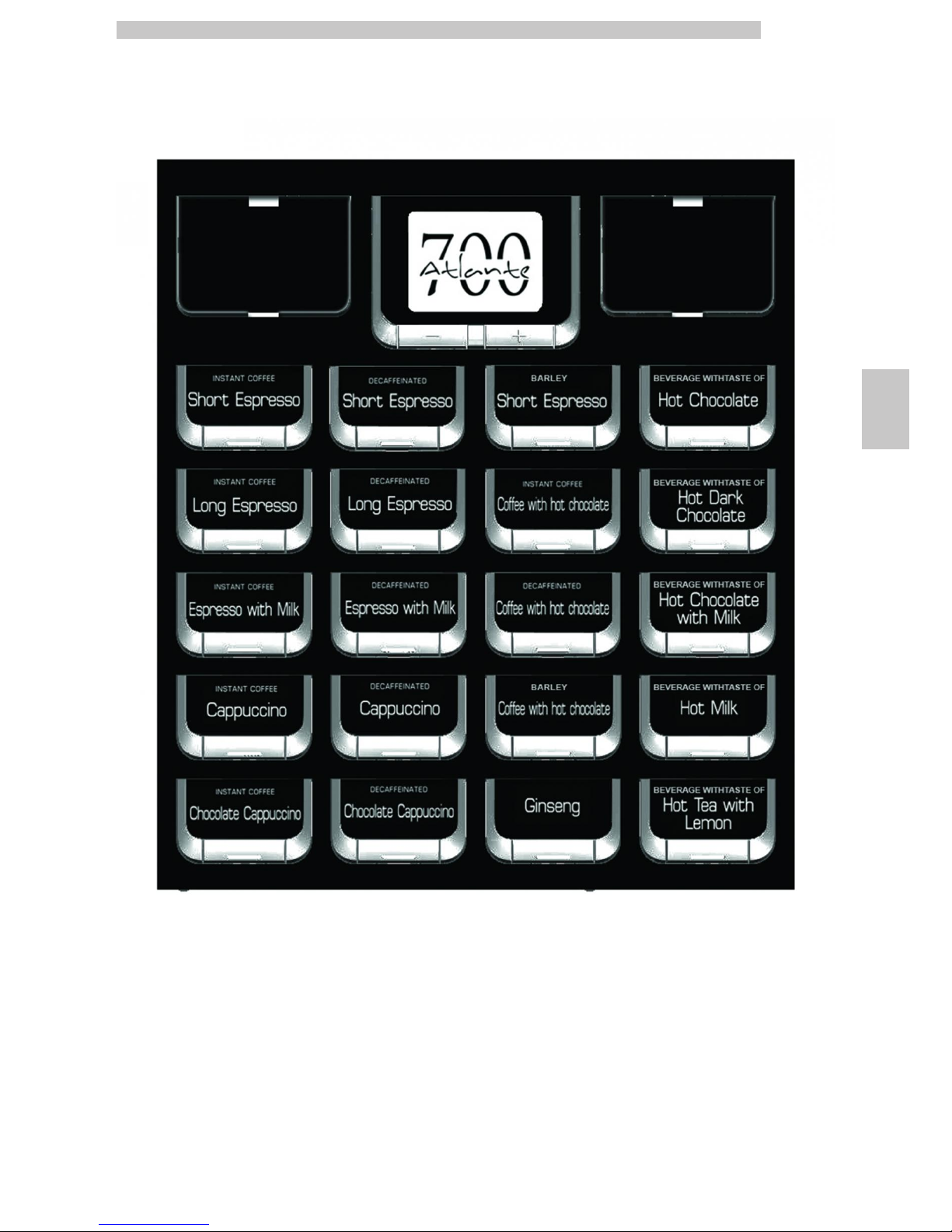
5.4 Label application
5.4.1 Product labels
Remove the cup dispenser and unscrew the 4 knobs
holding the keypad panel in place.
Remove the protection and disconnect the connectors.
Withdraw the keypad panel.
Insert the product labels.
Check the exact position of the labels against the selection
key.
English
5
26
Standard product configuration
Atlante 500 Instant
English
5
27
Standard product configuration
Atlante 700 Instant

English
5
28
Standard product configuration
ATLANTE 500 1 macina
 Loading...