

Page 1

OWNER’S OPERATING MANUAL
TRIMMING AND ROUTING KIT
MODEL EVT400K
1N.
1
/
2
1
SPECIFICATIONS :
Input................................ 400 watt
No Load Speed ...............30,000 min
-1
Max. Cutter Diameter ......6.35 mm
Weight .............................1.75 kg
THANK YOU FOR BUYING A RYOBI TRIMMING AND ROUTING KIT
Your new trimming and routing kit has been engineered and manufactured to Ryobi's high standard for
dependability, ease of operation and operator safety. Properly cared for, it will give you years of rugged,
trouble free performance.
CAUTION: Carefully read through this entire owner's manual before using your
trimming and routing kit.
Pay close attention to the Rules for Safe Operation, Warnings, and Cautions.
If you use your trimming and routing kit properly and only for what it is intended, you will enjoy years of
safe, reliable service.
Thank You again for buying Ryobi tools.
SAVE THIS MANUAL FOR FUTURE REFERENCE.
DOUBLEDOUBLE
DOUBLE
DOUBLEDOUBLE
INSULATEDINSULATED
INSULATED
INSULATEDINSULATED
N197
Page 2

RULES FOR SAFE OPERATION
The purpose of safety rules is to attract your attention to
possible dangers. The safety symbols and the explanations
with them, require your careful attention and understanding.
The safety warnings do not by themselves eliminate any
danger. The instr uction or warnings they give are not
substitutes for proper accident prevention measures.
SAFETY ALERT SYMBOL. Indicates caution
or warning. May be used in conjunction with
other symbols or pictures.
WARNING: Failure to obey a safety warning can
result in serious injury to yourself or to others.
Always follow the safety precautions to reduce
the risk of fire, electric shock and personal injury.
WARNING: Do not attempt to operate this tool
until you have read thoroughly and understood
completely, safety rules, etc. contained in this
manual. Failure to comply can result in
accidents involving fire, electric shock or serious
personal injury. Save owners manual and
review frequently for continuing safe operation
and instructing others who may use this tool.
The operation of any tool can
result in foreign objects being
thrown into your eyes, which can
result in severe eye damage.
Before beginning power tool
goggles or safety glasses with side shields and a full
face shield when needed. We recommend Wide Vision
Safety Mask for use over eyeglasses or standard safety
glasses with side shields.
1. KNOW YOUR POWER TOOL. Read owners manual
carefully. Learn its applications and limitations as well as
the specific potential hazards related to this tool.
2. GUARD AGAINST ELECTRICAL SHOCK BY
PREVENTING BODY CONTACT WITH GROUNDED
SURFACES. For example, pipes, radiators, ranges,
refrigerator enclosures.
3. KEEP WORK AREA CLEAN. Cluttered areas and
benches invite accidents.
4. AVOID DANGEROUS ENVIRONMENT. Don't use power
tools in damp or wet locations or expose to rain. Keep
work area well lit.
5. KEEP CHILDREN AND VISITORS A WAY. Visitors should
wear safety glasses and be kept a safe distance from
work area. Do not let visitors contact tool or extension
cord.
6. STORE IDLE TOOLS. When not in use, tools should be
stored in a dry and high or locked-up place, out of reach
of children.
7. DON'T FORCE TOOL. It will do the job better and safer
at the rate at which it was designed.
8. USE RIGHT TOOL. Don't force small tool or attachment
to do the job of a heavy duty tool. Don't use tool for
purpose not intended.
operation, always wear safety
Page 2
9. DRESS PROPERLY. Do not wear loose clothing or
jewellery. They can be caught in moving parts. Rubber
gloves and non-skid footwear are recommended when
working outdoors. Also wear protective hair covering to
contain long hair.
10.ALWAYS WEAR SAFETY GLASSES. Everyday
eyeglasses have only impact resistant lenses, they are
not safety glasses.
11. PROTECT Y OUR LUNGS. Wear a dust mask if operation
is dusty.
12.PROTECT YOUR HEARING. Wear hear ing protection
during extended periods of operation.
13.DON'T OVERREACH. Keep proper footing and balance
at all times. Do not use tool on a ladder or unstable
support. Secure tools when working at elevated levels.
14.MAINTAIN TOOLS WITH CARE. Keep tools sharp and
clean for better and safer performance. Follow
instructions for lubricating and changing accessories.
15.REMOVE ADJUSTING KEYS AND WRENCHES. Form
a habit of checking to see that keys and adjusting
wrenches are removed from tool before turning it on.
16.NEVER USE IN AN EXPLOSIVE ATMOSPHERE.
Normal sparking of the motor could ignite fumes.
17.KEEP HANDLES DRY, CLEAN AND FREE FROM OIL
AND GREASE. Always use a clean cloth when cleaning.
Never use brake fluids, gasoline, petroleum based
products, or any strong solvents to clean your tool.
18.STAY ALERT AND EXERCISE CONTROL. Watch what
you are doing and use common sense. Do not operate
tool when you are tired. Do not rush operation of tool.
19.CHECK DAMAGED PARTS. Before further use of the
tool, a guard or any other part that is damaged should
be carefully checked to determine that it will operate
properly and perform its intended function. Check for
alignment of moving parts, binding of moving parts,
breakage of parts, mounting and any other conditions
that may affect its operation. A guard or any other part
that is damaged should be properly repaired or replaced
by an authorised service centre.
20.DO NOT USE TOOL IF SWITCH DOES NOT TURN IT
ON AND OFF. Have defective switches replaced by
authorised service centre.
21.DO NOT OPERATE THIS TOOL WHILE UNDER THE
INFLUENCE OF DRUGS, ALCOHOL OR ANY
MEDICATION.
22.THE APPLIANCE IS NOT INTENDED FOR USE BY
YOUNG OR INFIRM PERSONS WITHOUT
SUPERVISION. YOUNG CHILDREN SHOULD BE
SUPERVISED TO ENSURE THAT THEY DO NOT PLAY
WITH THE APPLIANCE.
SAVE THESE INSTRUCTIONS
FOR FUTURE REFERENCE
Due to continued product
refinement policy, product features
and specifications can and will
change without notice. Check
current features and specifications
with your retailer.
Page 3
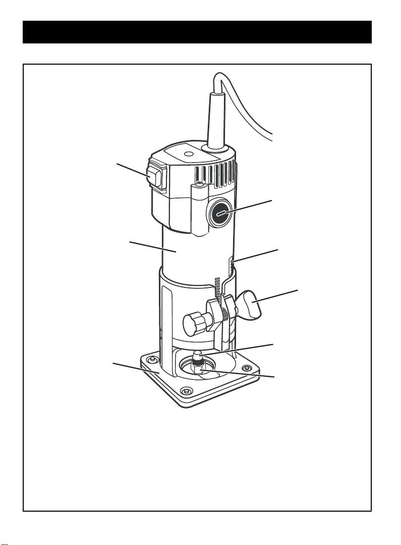
FEATURES
1
3
4
2
1. On/ Off Switch
2. Base
3. External Brush Cap
4. Motor Housing
Page 3
1N.
1
/
2
1
7
8
5
6
5. Collet
6. Collet Nut
7. Depth Of Cut Scale
8. Wing Bolt
Page 4

APPLICATIONS
You may use the trimming and routing kit for the
purposes listed below:
Routing all types of timber.
Cabinet making, trimming counter tops and finishing
work.
Trimming wood and plastics.
ASSEMBLY
WARNING:
Your trimming and routing kit should never be
connected to a power supply when you are
assembling parts, making adjustments,
installing or removing cutters, or when not in
use. Disconnecting your trimmer will prevent
accidental starting that could cause serious
injury.
WARNING:
Do not use cutters with undersized shanks.
Undersized shanks will not tighten properly
and could be thrown from tool causing injury.
WARNING:
Do not use cutters that are larger in diameter
than the opening in trimmer base. Use of
such cutters will come in contact with the
trimmer base and damage both the cutter
and trimmer base. Possible loss of control or
create other hazardous conditions that could
cause possible serious personal injury.
INSTALLING/REMOVING CUTTERS (Fig. 1)
UNPLUG YOUR TRIMMER.
ASSEMBLY
If installing a cutter for the first time, it can be installed
once the collet nut is loose. If changing cutters, cutter
will easily slip from collet after loosening collet nut.
The collet is machined to precision tolerances to fit
cutters with 6.35 mm diameter shanks.
With your trimmer still upside down on a workbench,
insert shank of cutter into collet. The shank of your
cutter should be close to but not touching the bottom of
the collet. This allows for expansion when the cutter
gets hot.
Tighten the collet nut securely by turning clockwise
with the wrench provided.
WARNING:
If collet nut is not tightened securely, cutter
may come out during use, causing serious
personal injury.
WARNING:
Avoid open area of trimmer base. Serious
personal injury will result from contact with a
rotating cutter.
Wrench On
Collet Nut
Cutter
Wrench On
Spindle Flats
WARNING:
Failure to unplug your trimmer could result in
accidental starting causing serious injury.
Place your trimmer upside down on a workbench in
order to gain easy access to the spindle and collet nut.
Place the small end of one of the wrenches provided
on the spindle flats. This will hold the spindle
stationary.
Place the large end of the other wrench provided onto
the collet nut. Rotate wrench counterclockwise to
loosen collet nut.
WARNING:
If you are changing a cutter immediately after
use, be careful not to touch the cutter or collet
with your hands or fingers. They may get burnt
due to the heat buildup from cutting.
Always use the wrench provide.
TO SET THE DEPTH OF CUT (Fig. 2)
UNPLUG YOUR TRIMMER
WARNING:
Failure to unplug your trimmer could result in
accidental starting causing serious injury.
Loosen the wing bolt and move the base until the tip of
cutter touches the work surface. The depth of cut is
zero at this point.
Position your trimmer so that the cutter can extend
below the sub base for desired depth of cut setting.
Move the base to obtain the desired depth of cut. The
distance the cutter moves will be indicated on the
depth of cut scale. Each mark on the scale indicates a
1.6 mm change in depth setting. Indicator points are
located on the base.
Securely tighten the wing bolt.
Page 4
Fig. 1
Page 5

CHANGING THE ROTATION SPEED (FIG. 7)
Depth of
Cut Scale
CM
1N.
1
1
/
2
1N.
1
/
2
1
2
1
3
OPERATION
CIRCUMFERENCE CUTTING (Fig. 4 - 6)
By installing the straight fence and connector you can
make a circumference cut. Available radius cuts, shown
from bit to central hole.
Minimum radius: 70mm
Maximum radius: 220mm
Attention: The straight fence is unable to cut a radius
between 172mm and 186mm.
Wing Bolt
Fig. 2
OPERATION
WARNING:
Always wear safety goggles or safety glasses
with side shields when using your trimmer.
Failure to do so could result in dust,
shavings, chips, loose particles
objects being thrown into your eyes resulting
in possible serious injury. If the operation is
dusty, also wear a face or dust mask.
WARNING:
When turning your trimmer ON, be prepared
for start-up torque. Always have a firm grasp
of your trimmer before starting. Because of
the high cutter speed rotation your trimmer
has a tendency to twist, jerk or grab in your
hands during start-up. If not prepared, this
can cause a loss of control resulting in
possible serious injury.
STRAIGHT FENCE (Fig. 3)
It is helpful to use the straight fence when trimming the
straight edge or engraving a groove.
Tighten the screw to install straight fence. Loosen the
wing bolt to adjust the required distance between bit and
fence. Then tighten the bolt. Keep the fence even with the
workpiece edge when cutting and moving the tool.
Screw
Fence
Wing Bolts
or foreign
Fig. 3
Wing Bolt
Washer
Center Hole
Bolt
Correctly aline the fence central hole to the required
circle’s center. Pushing a nail, with a diameter no more
than 6mm into the hole, to firmly fix the fence. Move the
tool around the nail in a clockwise direction.
Fence
Connector
Fig. 4
Fig. 5
Nail
Center Hole
Fence
Fig. 6
ADJUSTING THE GUIDE (Fig. 7 & 8)
It is much easier to use the adjusting guide for curve
cutting and trimming. Move the guide along the curved
edge.
Tighten the screw to install the adjusting guide on the tool
base plate. Loosen the wing bolt to adjust the guide.
Then tighten the screw firmly to fix the adjusting guide at
a required distance.
Install the guide into the base by bolt A. Adjust the
distance between the bit and base by bolt B, then fasten
by bolt C.
Page 5
Page 6

OPERATION
Bolt A
Bolt C
Bolt B
Fig. 7
When using the tool, please keep the guide mounted on
the workpiece edge.
Bit
Workpiece
Guide
Fig. 8
DEPTH OF CUT (Fig. 9)
As previously mentioned, the depth of cut is important
because it affects the rate of feed which, in turn, affects
the quality of a cut (and also, the possibility of damage to
your trimmer motor and cutter). A deep cut requires a
slower feed than a shallow cut and a too deep cut will
cause you to slow the feed so much that the cutter is no
longer cutting.
Making a deep cut is never advisable. The smaller cutters
especially those only 1.6 mm in diameter are easily
broken when subjected to too much side thrust. A
large cutter may not break, but if the cut is too deep
a rough cut will result and it may be very difficult
to guide and control the cutter as desired. For these
reasons, we recommend that you do not exceed 3 mm
depth of cut in a single pass, regardless of the cutter size
or the softness or condition of the workpiece. This will
result in a higher quality cut.
To make deeper cuts it is therefore necessary to make as
many successive passes as required, lowering the cutter
3 mm for each new pass. In order to save time, do all the
cutting necessary at one depth setting, before lowering
the cutter for the next pass. This will also ensure a
uniform depth when the final pass is completed.
WARNING:
If desired depth of cut is greater than can be
safely cut in one pass, make cuts in two or
more passes.
Depth
of Cut
1ST.Pass
Trimmer Feed
Direction
Trimmer Feed
Direction
Grains First
1ST.
Pass
2ND.
Pass
DIRECTION OF FEED AND THRUST (Fig. 10)
The trimmer motor and cutter revolve in a clockwise
direction. This gives the tool a slight tendency to twist (in
your hands) in a counterclockwise direction, especially
when the motor starts.
Because of the extremely high speed of cutter rotation
during “proper feeding” operation, there is very little
kickback under normal conditions. However, should the
cutter strike a knot, hard grain, foreign object etc, that
would affect the normal progress of the cutting action,
there will be a slight kickback — sufficient to spoil the
trueness of your cut if you are not prepared. Such a
kickback is always in the direction opposite to the
direction of cutter rotation.
To guard against such kickback, plan your setup and
direction of feed so that you will always be thrusting the
tool to hold it against whatever you are using to guide the
cut in the same direction that the leading edge of the
cutter is moving. In short, the thrust should be in a
direction that keeps the sharp edges of the cutter
continuously biting straight into new (uncut) timber.
Trim End
Page 6
Width
of Cut
2ND.Pass
Fig. 9
Direction
Trimmer Feed
Bit
Rotation
Fig. 10
Page 7

MAINTENANCE
WARNING:
When servicing use only identical Ryobi
replacement parts. Use of any other parts may
create a hazard or cause product damage.
BRUSH REPLACEMENT (Fig. 11)
Your trimmer has externally accessible brush
assemblies that should periodically be checked for
wear. Proceed as follows when replacement is
required:
UNPLUG YOUR TRIMMER.
WARNING:
Failure to unplug your trimmer could result in
accidental starting causing serious injury.
Remove the brush cap with a flat blade screwdriver.
Brush assembly is spring loaded and will pop out when
you remove the brush cap.
Remove
Check for wear. If worn, always replace in pairs. DO
Make sure curvature of brush matches curvature of
Make sure the brush cap is oriented correctly (straight)
the brush assembly (brush and spring).
NOT replace one side without replacing the other.
Reassemble using new brush assemblies.
motor and that the brush moves freely in the brush tube.
and replace.
Tighten the brush cap securely. DO NOT over tighten.
PROPER CARE OF CUTTERS
Get faster more accurate cutting results by keeping
cutters clean and sharp. Remove all accumulated pitch
and gum from cutters after each use.
When sharpening cutters, sharpen only the inside of the
cutting edge. Never grind the outside diameter. Be sure
when sharpening the end of a cutter to grind the
clearance angle the same as originally ground.
PROPER CARE OF COLLET
From time to time, it also becomes necessary to clean
your collet and collet nut. To do so, simply remove collet
nut from the collet and clean the dust and chips that have
Collected. Then return the collet nut to its original position.
GENERAL
Avoid using solvents when cleaning plastic parts. Most
plastics are susceptible to damage from various types of
commercial solvents and may be damaged by their use.
Brush Cap
Brush
Brush Cap
Assembly
1N.
1
/
2
1
Brush
Assembly
Fig. 11
WARNING:
Do not at anytime let brake fluids, fuel,
petroleum-based products, penetrating oils,
etc. come in contact with plastic parts. They
contain chemicals that can damage,
or destroy plastic.
weaken
Use clean cloths to remove dirt, carbon dust, etc.
When electric tools are used on fibreglass boats, sports
cars, wallboard, spackling compounds or plaster, it has
been found that they are subject to accelerated wear and
possible premature failure, as the fiberglass chips and
grindings are highly abrasive to bearings, brushes,
commutators, etc. Consequently it is not recommended
that this tool be used for extended work on any fiberglass
material, wallboard, spackling compounds or plaster.
During any use on these materials, it is extremely
important that the tool is cleaned frequently by blowing
with an air jet.
WARNING:
Always wear safety goggles or safety
glasses with side shields during power tool
operation or when blowing dust. If operation
is dusty, also wear a dust mask.
LUBRICATION
All of the bearings in this tool are lubricated with a
sufficient amount of high grade lubricant for the life of the
unit under normal operating conditions. Therefore, no
further lubrication is required.
Page 7
Page 8

RYOBI TECHNOLOGIES A USTRALIA PTY. L TD .
GUARANTEE
Subject to the guarantee condition below, this Ry obi tool
(hereinafter called “the product”) is guaranteed by Ryobi
(hereinafter called “the Company”) to be free from
defects in material or workmanship for a period of 24
months from the date of original purchase covering
both parts and labour. Under the terms of this
guarantee, the repair or replacement of any part shall
be the opinion of the Company or its authorised agent.
Should service become necessary during the warranty
period, the owner should contact the Authorised Ryobi
Retailer from whom the Product was purchased, or the
nearest Company Branch Office. In order to obtain
guarantee service, the owner must present the sales
docket and Guarantee Certificate to confirm date of
purchase. This product is sold b y the dealer or agent as
principal and the dealer has no authority from the
Company to give any additional guarantee on the
Company’s behalf except as herein contained or herein
referred to.
Guarantee Conditions
This guarantee only applies provided that the Product
has been used in accordance with the manufacturer’ s
recommendations under normal use and reasonable
care (in the opinion of the Company) and such
RYOBI TECHNOLOGIES AUSTRALIA PTY. LTD.
SYDNEY: 359-361 Horsley Road, Milperra, N.S.W. 2214.
Tel: (02) 9792 9888 - Fax: 1800 807 993 - www.ryobi.com.au
BRISBANE: All enquiries Tel : 1300 361 505
TOWNSVILLE: All enquiries Tel : 1300 361 505
MELBOURNE: 960 Stud Road, Rowville,Vic. 3178
AUCKLAND: 503 Mt Wellington Highway, Mt Wellington, N.Z.
Tel: (09) 573 0230 - Free Call: 0800 279 624 - Fax: (09) 573 0231 - www.ryobi.co.nz
A.B.N. 98 002 277 509
Contact during normal business hours.
RYOBI NEW ZEALAND PTY. LTD.
Contact during normal business hours.
guarantee does not cover damage, malfunction or
failure resulting from misuse, neglect, abuse, or used
for a purpose for which it was not designed or is
not suited and no repairs, alterations or
modifications have been attempted by other than
an Authorised Service Agent. This guar antee will not
apply if the tool is damaged by accident or if repairs
arise from normal wear and tear.
The Company accepts no additional liability pursuant
to this guarantee for the costs of travelling
or transportation of the Product or parts to and from
the service dealer or agent - such costs are not included
in this guarantee.
Certain legislation, including the T r ade Practices Act,
1974 (as amended) and other state and territorial laws
give rights to the buyer and impose liability on the seller
in certain circumstances. Nothing herein shall hav e the
effect of excluding, restricting or modifying any
condition, guarantee, right or liability imposed, to the
extent only that such exclusion, restriction or
modification would render any term herein void.
HOBART:
All enquiries Tel : 1300 360 216
ADELAID: All enquiries Tel : 1300 360 216
33-35 Sorbonne Cres., Canning Vale,W.A. 6155.
PERTH:
Tel : (08) 9455 7775
This Guarantee Form Should Be Retained By The Customer At All Times
For your record and to assist in establishing date of purchase (necessary for in-guarantee service)
please keep your purchase docket and this for m completed with the following particulars.
Purchased From
Address Of Dealer
Date Model No Serial No
Present This Form With Your Purchase Docket When Guarantee Service Is Required.
 Loading...