

ERT1250RG / ERT1250VN
PLUNGE ROUTER
OWNER’S OPERATING MANUAL
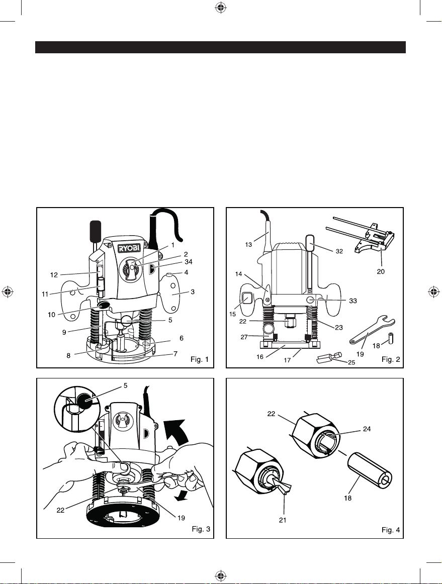
1. Speed selection sight window
2. Variable speed control
3. Handle
4. Lock-off button
5. Spindle lock button
6. Parallel guide lock knob
7. Chip shield
8. Depth stop
9. Depth stop bar
10. Depth stop bar lock knob
11. Depth zero reset indicator
12. Scale
13. Power cord
DESCRIPTION
14. Plunge lock lever
15. Switch
16. Router base
17. Sub-base
18. Collet adaptor
19. Spanner (23.8 mm)
20. Parallel guide
21. Cutter
22. Collet nut
23. Threaded post
24. Collet
25. Router bits
26. Workpiece
27. Dust port
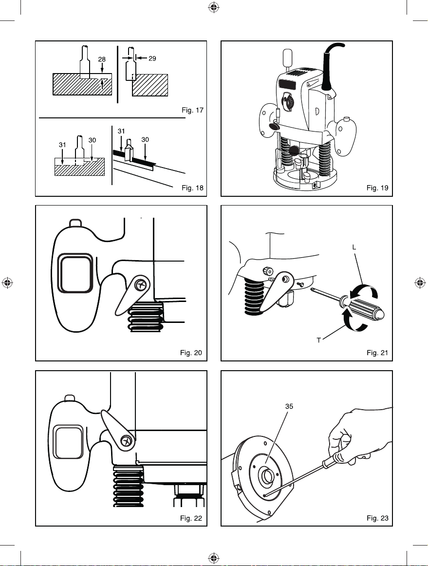
28. Depth of cut
29. Width of cut
30. First pass
31. Second pass
32. Fine height adjuster knob
33. Fine height adjuster quick
release button
34. Live tool indicator
35. Template guide
36. Screw
37. Locking anchor
33
26
37
27

Important!
It is essential that you read the instructions in this manual before
operating this machine.
Subject to technical modifications.

GENERAL POWER TOOL SAFETY WARNINGS
WARNING
Read all safety warnings and all instructions. Failure
to follow the warnings and instructions may result in
electric shock, fi re and/or serious injury.
Save all warnings and instructions for future
reference.
The term “power tool” in the warnings refers to your
mains-operated (corded) power tool or battery-operated
(cordless) power tool.
1. WORK AREA SAFETY
a. Keep work area clean and well lit. Cluttered or
dark areas invite accidents.
b. Do not operate power tools in explosive
atmospheres, such as in the presence of
flammable liquids, gases, or dust. Power tools
create sparks which may ignite the dust or fumes.
c. Keep children and bystanders away while
operating a power tool. Distractions can cause
you to lose control.
2. ELECTRICAL SAFETY
a. Power tool plugs must match the outlet. Never
modify the plug in any way. Do not use any
adaptor plugs with earthed (grounded) power
tools. Unmodifi ed plugs and matching outlets will
reduce risk of electric shock.
b. Avoid body contact with earthed or grounded
surfaces such as pipes, radiators, ranges and
refrigerators. There is an increased risk of electric
shock if your body is earthed or grounded.
c. Do not expose power tools to rain or wet
conditions. Water entering a power tool will
increase the risk of electric shock.
d. Do not abuse the cord. Never use the cord for
carrying, pulling or unplugging the power tool.
Keep cord away from heat, oil, sharp edges
or moving parts. Damaged or entangled cords
increase the risk of electric shock.
e. When operating a power tool outdoors, use an
extension cord suitable for outdoor use. Use of
a cord suitable for outdoor use reduces the risk of
electric shock.
f. If operating power tools in a damp location
is unavoidable, use a residual current device
(RCD) protected supply. Use of an RCD reduces
the risk of electric shock.
3. PERSONAL SAFETY
a. Stay alert, watch what you are doing and
use common sense when operating a power
tool. Do not use a power tool while you are
tired or under the influence of drugs, alcohol
or medication. A moment of inattention while
operating power tools may result in serious
personal injury.
b. Use personal protective equipment. Always
wear eye protection. Protective equipment such
as dust mask, non-skid safety shoes, hard hat, or
hearing protection used for appropriate conditions
will reduce personal injuries.
c. Prevent unintentional starting. Ensure the
switch is in the off-position before connecting
to power source and/or battery pack, picking
up or carrying the tool. Carrying power tools with
your fi nger on the switch or energising power tools
that have the switch on invites accidents.
d. Remove any adjusting key or wrench before
turning the power tool on. A wrench or a key left
attached to a rotating part of the power tool may
result in personal injury.
e. Do not overreach. Keep proper footing and
balance at all times. This enables better control
of the power tool in unexpected situations.
f. Dress properly. Do not wear loose clothing or
jewellery. Keep your hair, clothing and gloves
away from moving parts. Loose clothes, jewellery
or long hair can be caught in moving parts.
g. If devices are provided for the connection of
dust extraction and collection facilities, ensure
these are connected and properly used. Use of
dust collection can reduce dust-related hazards.
4. POWER TOOL USE AND CARE
a. Do not force the power tool. Use the correct
power tool for your application.
power tool will do the job better and safer at the
rate for which it was designed.
b. Do not use the power tool if the switch does not
turn it on and off. Any power tool that can not be
controlled with the switch is dangerous and must
be repaired.
c. Disconnect the plug from the power source
and/or the battery pack from the power tool
before making any adjustments, changing
accessories, or storing power tools. Such
preventive safety measures reduce the risk of
starting the power tool accidentally.
d. Store idle power tools out of the reach of
children and do not allow persons unfamiliar
with the power tool or these instructions
to operate the power tool. Power tools are
dangerous in the hands of untrained users.
e. Maintain power tools. Check for misalignment
or binding of moving parts, breakage of parts
and any other condition that may affect the
power tools operation. If damaged, have the
power tool repaired before use. Many accidents
are caused by poorly maintained power tools.
f. Keep cutting tools sharp and clean. Properly
maintained cutting tools with sharp cutting edges
are less likely to bind and are easier to control.
1
The correct

g. Use the power tool, accessories and tool bits
etc., in accordance with these instructions and
in the manner intended for the particular type
of power tool, taking into account the working
conditions and the work to be performed. Use
of the power tool for operations different from
intended could result in a hazardous situation.
5. SERVICE
a. Have your power tool serviced by a qualified
repair person using only identical replacement
parts. This will ensure that the safety of the power
tool is maintained.
SPECIAL SAFETY RULES
a. Hold tool by insulated gripping surfaces when
performing an operation where the cutting tool
may contact hidden wiring or its cord. Contact
with a “live” wire will make exposed metal parts of
the tool “live” and shock the operator.
b. Know your power tool. Read operator’s manual
carefully. Learn its applications and limitations, as
well as the specifi c potential hazards related to
this tool. Following this rule will reduce the risk of
electric shock, fi re, or serious injury.
c. Always wear safety glasses. Everyday
eyeglasses have only impact-resistant lenses;
they are NOT safety glasses. Following this rule
will reduce the risk of serious personal injury.
d. Protect your lungs. Wear a face or dust mask
if the operation is dusty. Following this rule will
reduce the risk of serious personal injury.
e. Protect your hearing. Wear hearing protection
during extended periods of operation. Following
this rule will reduce the risk of serious personal
injury.
f. Inspect tool cords periodically and, if damaged,
have them repaired at your nearest factory service
center or other authorised Service Organisation.
g. Constantly stay aware of cord location.
Following this rule will reduce the risk of electric
shock or fi re.
h. Check damaged parts. Before further use of the
tool, a guard or other part that is damaged should
be carefully checked to determine that it will
operate properly and perform its intended function.
Check for alignment of moving parts, binding of
moving parts, breakage of parts, mounting, and
any other conditions that may affect its operation.
A guard or other part that is damaged should be
properly repaired or replaced by an authorised
service center. Following this rule will reduce the risk
of shock, fi re, or serious injury.
i. Do not abuse cord. Never carry the tool by the
cord or yank it to disconnect it from the receptacle.
Keep cord away from heat, oil, and sharp edges.
Following this rule will reduce the risk of electric
shock or fi re.
j. Inspect for and remove all nails from lumber
before routing. Following this rule will reduce the
risk of serious personal injury.
k. Drugs, alcohol, medication. Do not operate tool
while under the infl uence of drugs, alcohol, or any
medication. Following this rule will reduce the risk
of electric shock, fi re, or serious personal injury.
l. Save these instructions. Refer to them frequently
and use them to instruct others who may use this
tool. If you loan someone this tool, loan them these
instructions also.
m. This product is not intended for use by
persons (including children) with reduced
physical, sensory or mental capabilities, or
lack of experience and knowledge, unless they
have been given supervision or instruction
concerning use of the product by a person
responsible for their safety. Children should be
supervised to ensure that they do not play with
the product.
n. Keep children and visitors away. Visitors should
wear safety glasses and be kept at a safe distance
from work area. Do not let visitors come in contact
with the tool or the extension cord.
o. Complies with AS/NZS 60745.
p. It is recommended that this tool always be supplied
via a residual current device with a rated residual
current of 30mA or less.
WARNING
Some dust created by power sanding, sawing, grinding,
drilling, and other construction activities contains
chemicals known to cause cancer, birth defects or other
reproductive harm.
Some examples of these chemicals are:
lead from lead-based paints
crystalline silica from bricks and cement and
other masonry products
arsenic and chromium from chemically-treated
lumber
Your risk from these exposures varies, depending on
how often you do this type of work. To reduce your
exposure to these chemicals, work in a well ventilated
area, and work with approved safety equipment, such
as those dust masks that are specially designed to fi lter
out microscopic particles.
SYMBOL
Safety Alert
V Volts
Hz Hertz
Alternating Current
W Watts
2

nₒ No-load speed
n Rated speed
min־¹ Revolutions or reciprocations per minute
Conformity
Double insulation
Wear ear protection
Wear eye protection
Please read the instructions carefully before
starting the product.
Waste electrical products should not be
disposed of with household waste. Please
recycle where facilities exist. Check with your
Local Authority or retailer for recycling advice.
Recycle raw materials instead of disposing
of as waste. The machine, accessories and
packaging should be sorted for environmentalfriendly recycling.
SPECIFICATIONS
Voltage 240 V 50 Hz
No load speed 14000-31500 min־¹
Input power 1250 W
Plunge depth 55 mm
Collet size 6.35 mm or 12.7 mm
Peak horsepower 1.5 HP
Net weight 4.5 kg
APPLICATIONS
Use your router only for the purposes listed below:
routing grooves, shaping edges, freehand designs,
etc., in wood
chamfering, rabbeting, dadoing, and dovetailing in
wood
routing edges on laminates
FEATURES
Your plunge router is a versatile woodworking tool that
will give you years of trouble-free performance. It is
engineered with the professional in mind, but its ease
of operation allows the amateur to produce work that is
beautiful and precise. As the name implies, your plunge
router can be used for making plunge cuts in workpieces,
routing grooves, edge routing, routing circles, and
freehand routing.
When used with recommended accessories, such as
depth adjustment knob, and straight guide; it becomes
even more versatile. Various types of cutters, both with
and without roller bearings as guides, also add to the
versatility of this tool.
HEAVY DUTY MOTOR
Your router has a powerful motor with sufficient power to
handle tough routing jobs. It delivers 1.5 horsepower for
heavy duty performance.
CHIP SHIELD
A plastic chip shield has been provided on the base of
your router for protection against fl ying dust and chips. It is
designed to fi t the front opening of the router base.
SPINDLE LOCK
The spindle lock secures the spindle so that only one
wrench is needed to loosen collet nut and change cutters.
To operate, push the button whilst loosening the collet.
NOTE: Do not run router with spindle lock engaged or use
as a brake to stop the router.
VARIABLE SPEED
Your router has advanced electronic features, designed to
assist you in getting the maximum use from your router.
By making proper speed selections, your router can be
adjusted to specifi c routing needs.
The variable speed control allows the router to develop a
no load speed that can be adjusted from 14,000 to 31,500
min־¹. The variable speed control selector is conveniently
located on the front of the router.
The electronic feature of your router introduces the
fl exibility of adjusting the motor speed to required job
conditions. An electronic speed control module senses
the load applied to the motor, and increases or decreases
motor voltage to compensate for and maintain desired
RPM. Speed can be set according to the approximate
cutter diameter you will be using and to the hardness of
the material being cut. The best cuts are made when the
cutter is fed through material at the proper rate of feed.
PLUNGE LOCK LEVER
Your router has a plunge lock lever that allows for free
plunging. This feature is very useful when used with the
fine height adjuster quick release mechanism. Unlocking
the plunge lock lever and releasing the fine height adjuster
allows for a smooth, precise plunging action. Once you
reach the desired depth of cut, simply lock the plunge lock
lever. The cutter will then be secured at the desired depth
of cut. After extended use, the plunge lock may wear. If
this happens, you can easily adjust the lever.
3

To adjust plunge lock lever
See fi gure 21.
Unplug the tool.
WARNING
Failure to unplug the tool could result in accidental
starting, causing serious injury.
Make sure lever is in locked position.
Remove (L) the screw supporting the plunge lock
lever.
Remove the lever.
Place the lever back in the original locked position.
Replace (T) the screw.
Check for free plunge with lever rotated to unlocked
position. If router does not plunge freely, reposition
lever.
Plunge lock lever shown after extended wear
See fi gure 20.
Plunge lock lever shown in original locked position
See fi gure 22.
TEMPLATE GUIDE
See fi gure 23.
The template guide can be fi tted to the base of the router
to accurately duplicate curves and other complex shapes.
These shapes can be easily made by using a jigsaw to cut
out a template. Fix the guide to the base of the router by
removing the 3 screws retaining the dust extraction port,
placing the guide in the recess provided in the base and
replacing the screws. The dust extraction port must be in
place when fi tting the guide to hold the screws.
The guide protrudes below the bottom of the base allowing
the router to follow the template, which must be securely
fi xed to the workpiece and a fi rm pressure applied to the
router at all times to ensure that the edge of the guide
accurately follows the template.
The template must be at least 5 mm thick to allow for the
protrusion of the guide. Allowance must also be made in
the template for the distance between the cutting edge of
the bit and the outside edge of the template guide.
ERGONOMIC DESIGN
The design of this tool provides for easy handling. It is
designed for comfort and ease of grasp when operating in
different positions and at different angles.
ELECTRICAL CONNECTION
Your router has a precision built electric motor. It should
only be connected to a power supply of the type specifi ed
on the rating plate of the machine, AC only. Do not operate
this tool on direct current (DC). A voltage drop of more than
10 percent will cause a loss of power and overheating.
If your tool does not operate when plugged into an outlet,
double-check the power supply.
DOUBLE INSULATION
Double insulation is a concept in safety in electric power
tools, which eliminates the need for the usual threewire
grounded power cord. All exposed metal parts are isolated
from the internal metal motor components with protecting
insulation. Double insulated tools do not need to be
grounded.
WARNING
The double insulated system is intended to protect
the user from shock resulting from a break in the tools
internal wiring. Observe all normal safety precautions to
avoid electrical shock.
IMPORTANT
Servicing of a tool with double insulation requires
extreme care and knowledge of the system and should
be performed only by a qualifi ed service technician. For
service, we suggest you return the tool to your nearest
authorised service center for repair.
WARNING
Do not attempt to modify this tool or create accessories
not recommended for use with this tool. Any such
alteration or modifi cation is misuse and could result
in a hazardous condition leading to possible serious
personal injury.
ADJUSTMENTS
WARNING
The tool should never be connected to a power supply
when you are assembling parts, making adjustments,
installing or removing cutters, or when not in use.
Disconnecting the tool will prevent accidental starting
that could cause serious injury.
CUTTER INSTALLATION
See fi gure 3 and 4.
Unplug the tool.
WARNING
Failure to unplug the tool could result in accidental
starting, causing serious injury.
4

CAUTION
To prevent damage to the spindle or spindle lock,
always allow motor to come to a complete stop before
engaging the spindle lock.
Remove chip shield from router base.
Depress spindle lock.
Lay router down on workbench in order to gain easy
access to collet nut.
Place the spanner provided onto collet nut and turn
counterclockwise to loosen.
WARNING
If you are changing a cutter immediately after use, be
careful not to touch the cutter or collet with your hands
or fi ngers. They will get burned because of the heat
buildup from cutting. Always use the wrench provided.
Install cutter once collet nut is loose. If changing cutters,
cutter will easily slip from collet after loosening collet
nut. For example: The collet is machined to precision
tolerances to fit cutters with 12.7 mm diameter shanks.
To use cutters with 6.35 mm diameter shanks, insert
the 6.35 mm collet adaptor into the 12.7 mm collet.
Insert shank of cutter until shank bottoms out, then pull
it out 1.6 mm to allow for expansion when the bit gets
hot.
Tighten the collet nut securely by turning clockwise
with the spanner provided.
Release spindle lock.
Replace chip shield.
WARNING
If the collet nut is not securely tightened, the cutter may
detach during use causing serious personal injury.
WARNING
Do not use cutters with undersized shanks. Undersized
shanks will not tighten properly and could be thrown
from the tool causing injury.
WARNING
Do not use cutters that are larger in diameter than the
opening in router base. Use of such cutters will come
in contact with the router base and damage both the
cutter and router base. This situation could also cause
possible loss of control or create other hazardous
conditions that could cause possible serious personal
injury.
DEPTH OF CUT
When routing a groove that is too deep to safely cut in one
pass, it is best to make the cut in several passes.
We recommend that cuts be made at a depth not
exceeding 3.2 mm and that several passes be made to
reach deeper cuts.
Proper depth of cut depends on several factors such as
horsepower of the router motor, type of cutter being used
and the type of wood being routed. A lightweight, low
horsepower router is designed for making shallow cuts.
A router with high horsepower rating can safely cut
deeper. For example: small bits, such as veining bits
with 1.6 mm cutting diameters, are designed to remove
only small amounts of wood. Large bits, such as straightfl ute bits, are made to remove larger amounts of wood in
a single pass. Cuts can be made deeper in soft woods,
such as white pine, than in tough hardwoods, like oak or
maple. Based upon these considerations, choose a depth
of cut that will not place excessive strain on router motor.
If you fi nd that extra force is needed or that the motor
speed slows down considerably, turn off the router and
reduce the depth of cut. Then, make the cut in two or more
passes.
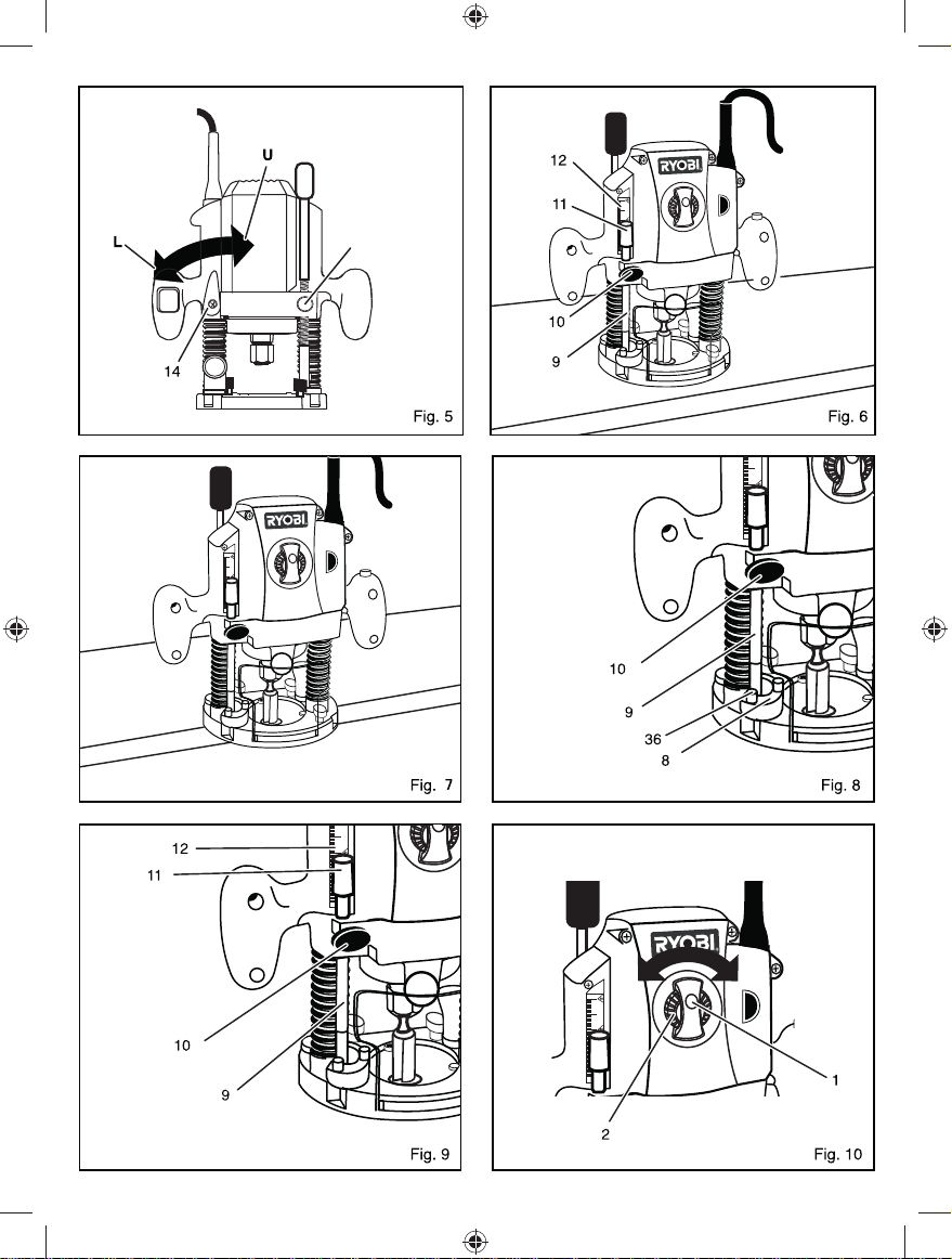
TO ADJUST DEPTH OF CUT
See fi gure 5 - 7.
Loosen the stop bar.
Unlock the plunge lock lever by turning it counter
clockwise.
Lower the router body until the cutter is in contact with
the workpiece.
Lock the depth stop at the right height.
Set the exact depth of cut using the graduation. The
distance between the stop bar and screw of the depth
stop is setting plunge depth.
Tighten the stop bar lock knob to set depth of plunge.
DEPTH STOP
See fi gure 8 - 9.
The depth stop can be used to set three different
depths. This is particularly useful for deep cut,
performed in steps.
If required, set all three screws.
VARIABLE SPEED CONTROL SELECTOR
See fi gure 10.
Your router has a variable speed control selector designed
to allow operator control of speed and torque limits. You
can make speed selections best suited to the type of cut,
the material being cut, and the size of bit being used.
The variable speed control selector allows you to adjust
router speed from 14,000 to 31,500 min־¹. There is a
six-step scale on the variable speed control selector. To
increase the speed and torque of your router, turn the
variable speed control selector to a higher setting. Turn to
5

a lower setting to decrease speed and torque.
NOTE: If you do not want to use the variable speed control
selector, turn it to the highest possible setting, and the
feature will not be active.
We suggest that you practice with the variable speed
feature of your router before installing a cutter and making
cuts in wood.
ZERO RESET INDICATOR
The zero reset indicator allows you to use the scale
provided on the housing to make quick depth of cut
changes to existing depth of cut settings. Choose a
reference point on the scale and slide the zero reset
indicator up or down the scale the distance required
for new depth of cut. Then change stop bar position by
loosening lock knob and adjusting stop bar until red line
on zero reset indicator moves back to reference point.
Tighten the lock knob securely to lock stop bar in new
position. The cutter position will now increase or decrease
the exact distance the stop bar was adjusted.
NOTE: Each mark on the inch scale indicates 1.6 mm.
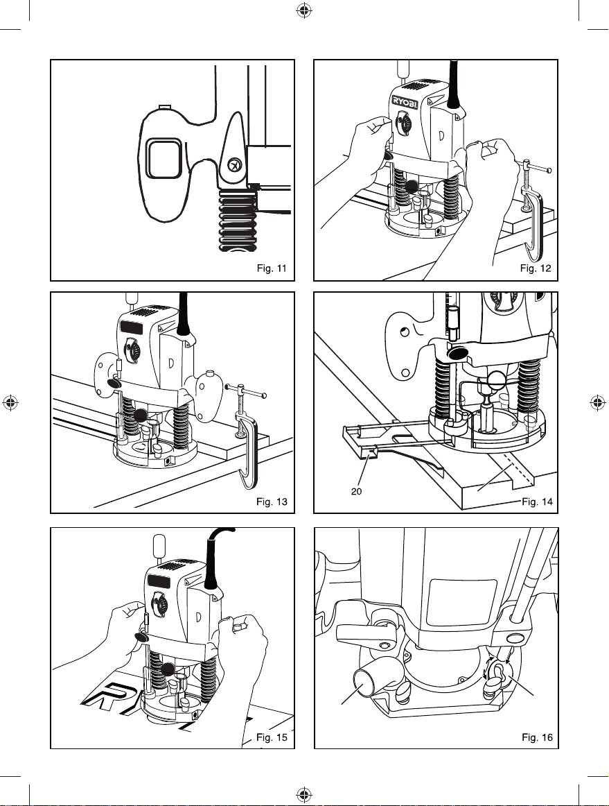
OPERATION
SWITCH
See fi gure 11.
To turn the router on, press the lock-off button and
squeeze the switch. To turn the router off, release both
the switch and lock-off button.
CAUTION
We suggest that you practice with the tool before
installing a cutter and making cuts in wood.
ROUTING
See fi gure 12.
For ease of operation and maintaining proper control, your
router has two handles, one on each side of the router
base. When using your router, hold it fi rmly with both
hands.
Before starting the router, unplug it and make sure the
cutter is securely tightened in collet nut and that depth of
cut is properly set.
Plug the router into a power supply, turn it on, and let the
motor build to its full speed, then gradually plunge or feed
the cutter into the workpiece. Do not let the cutter contact
the workpiece before turning on the router and allowing it
to develop to full speed.
Remain alert and watch what you are doing. Do not
operate the router when fatigue or under the influence of
drugs, alcohol or any medication.
ROUTING GROOVES
See fi gure 13.
When routing across the face of boards, set the router at
desired depth of cut, place the edge of the router base
against the workpiece, and turn on the router. Slowly feed
the cutter into the workpiece along the desired line of cut.
WARNING
If the desired depth of cut is greater than can be safely
cut in one pass, make cuts in two or more passes.
When routing straight cuts across stock, clamp a straightedge to the workpiece to use as a guide. Position the
straight-edge parallel to the line of cut and offset the
distance between the cutting edge of the cutter and the
edge of the router base. Hold the router base against the
straight-edge and rout the groove.
When routing a groove wider than the diameter of the
cutter, clamp a straight-edge on both sides of the cutlines.
Position both guides parallel to the desired line of cut
and space equal distances from the desired edges of the
groove. Rout along one guide, then reverse direction and
rout along the other guide. Clean out any remaining waste
in the center of the groove by freehand.
FITTING AND ADJUSTING THE PARALLEL GUIDE
See fi gure 14.
Insert the parallel guide into the hole of the router
base.
Draw a cutting line on the workpiece.
Lower the router body until the cutter is in contact with
the workpiece.
Position the router on the cutting line. The outer cutting
edge of the cutter must coincide with the cutting line.
Without moving the router, push the guide to the edge
of the workpiece before tightening the lock knob.
ROUTING BY FREEHAND
See fi gure 15.
When using freehand, your plunge router becomes a
fl exible and versatile tool. This fl exibility makes it possible
to easily rout signs, relief sculptures, etc. There are two
basic techniques for freehand routing:
routing letters, grooves, and patterns into wood
routing out the background, leaving the letters or
pattern raised above the surface
When freehand routing, we suggest the following:
draw or layout the pattern on workpiece
choose the appropriate cutter
NOTE: A core box or V-groove bit is often used for routing
letters and engraving objects. Straight bits and ball mills
are often used to make relief carvings. Veining bits are
used to carve small, intricate details.
Route the pattern in two or more passes. Make the first
pass at 25% of the desired depth of cut. This process
6

will provide better control as well as being a guide for
the next pass.
Do not rout deeper than 3.2 mm per pass or cut.
Follow these directions when routing by freehand:
Choose the appropriate cutter, set desired depth of
cut, carefully check set-up, and secure workpiece.
Make a test cut in a scrap piece of wood from the
same workpiece if possible.
Unlock plunge lock lever to raise cutter from any
preset depth of cut. This also permits raising cutter
inside router base.
Place router on workpiece inside pattern to be routed.
Grasp handles securely and press the switch to start
your router.
Let motor build to full speed, then gradually plunge
cutter into workpiece until stop bar comes into contact
with depth stop.
Lock plunge lock lever to secure depth of cut setting.
Begin routing out the pattern, continuing until a
complete pass at this depth of cut has been made.
WARNING
Do not use large router bits for freehand routing. Use
of large router bits when freehand routing could cause
loss of control or create other hazardous conditions that
could cause possible serious personal injury.
Several cuts that require repositioning of router may
be needed for a particular job. If this situation exists,
unlock plunge lock lever to raise cutter inside router
base after each cut, reposition router for next cut,
gradually plunge cutter into workpiece until stop
bar contacts depth stop, lock plunge lock lever and
continue routing.
After all cuts have been made, unlock plunge lock
lever, raise cutter inside router base, remove router
from workpiece, turn off the router, and allow cutter to
come to a complete stop.
ROUTING EDGES
Place router on workpiece, making sure the router bit does
not contact workpiece. Turn router on and let the motor
build to its full speed. Begin your cut, gradually feeding the
cutter into the workpiece.
WARNING
Keep a fi rm grip on the router with both hands at all
times. Failure to do so could result in loss of control
leading to possible serious injury.
Upon completion of cut, turn the motor off and let it come
to a complete stop before removing the router from work
surface.
WARNING
Never pull the router out of work and place upside down
on work surface before the cutter stops.
CONNECTING A DUST EXTRACTOR
See fi gure 16.
A dust extractor hose can be connected to the dust port.
USING THE FINE HEIGHT ADJUSTER
It is used to precisely control the depth of the cutter.
Ensure that the plunge lock is released.
Rotate the knob clockwise to raise the cutter,
anticlockwise to lower the cutter.
When the desired position is reached, re-engage the
plunge lock before use.
LOCKING ANCHOR FOR THREADED FINE HEIGHT
ADJUSTMENT ROD
See fi gure 16.
The locking anchor is located on the base of the router,
it is designed to hold the threaded fi ne height adjustment
rod in place to allow the fi ne height adjustment to operate.
When the fi ne height adjustment is required, release the
fi ne height adjuster quick release button and push down
on the fi ne height adjuster knob so that the bottom of the
threaded rod makes contact with the base and locking
anchor. Make sure the locking anchor is positioned so that
the bottom of the threaded rod goes into the right hand
side of the elongated hole (the larger side of the opening).
Once in place, turn the locking anchor to the right to secure
the threaded rod. To release, turn the locking anchor to
the left and push the fi ne height adjuster quick release
button and pull the fi ne height adjuster knob upwards.
FINE HEIGHT ADJUSTER QUICK RELEASE BUTTON
This disengages the fi ne height adjuster allowing large
adjustments of plunge depth to be quickly made.
To make large adjustments to cutter height, ensure
that the plunge lock is released.
Press the quick release button whilst plunging the
router to the required height.
Release the button, check the height, make fine
adjustments if necessary with the fine height adjuster,
then re-engage the plunge lock before use.
DEPTH OF CUT
The depth of cut is important because it affects the rate of
feed that, in turn, affects the quality of the cut (and also the
possibility of damage to your router motor and bit). A deep
cut requires a slower feed than a shallow one, and a too
deep cut will cause you to slow the feed so much that the
bit is no longer cutting, it is scraping, instead.
Making a deep cut is never advisable. The smaller bits are
easily broken off when subjected to too much side thrust.
A large enough bit may not be broken, but if the cut is too
7

deep, a rough cut will result, and it may be very diffi cult to
guide and control the bit as desired. For these reasons, we
recommend that you do not exceed 3.2 mm depth of cut in
a single pass, regardless of the bit size or the softness or
condition of the workpiece.
To make deeper cuts, it is therefore necessary to make as
many successive passes as required, lowering the bit to
3.2 mm for each new pass. In order to save time, do all the
cutting necessary at one depth setting, before lowering the
bit for the next pass. This will also assure a uniform depth
when the fi nal pass is completed.
LIVE TOOL INDICATOR
This tool features a live tool indicator which illuminates as
soon as the tool is connected to the supply. This warns the
user that the tool is connected and will operate when the
switch is pressed.
MAINTENANCE
WARNING
When servicing, use only identical Ryobi replacement
parts. Use of any other parts may create a hazard or
cause product damage.
GENERAL
Avoid using solvents when cleaning plastic parts. Most
plastics are susceptible to damage from various types
of commercial solvents. Use clean cloths to remove dirt,
carbon dust, etc.
WARNING
Do not at any time let brake fl uids, gasoline, petroleum-
based products, penetrating oils, etc., come in contact
with plastic parts. They contain chemicals that can
damage, weaken or destroy plastic.
LUBRICATION
All of the bearings in this tool are lubricated with a
suffi cient amount of high grade lubricant for the life of
the unit under normal operating conditions. Therefore, no
further lubrication is required.
CUTTERS
Get faster and more accurate cutting results by keeping
cutters clean and sharp. Remove all accumulated pitch
and gum from cutters after each use.
When sharpening cutters, sharpen only the inside of the
cutting edge. Never grind the outside diameter. When
sharpening the end of a cutter, make sure to grind the
clearance angle the same as originally ground.
COLLET
Dust and chips may collect on the collet from time to time,
making it necessary to clean the collet. To do so, remove
the collet assembly and wipe it with a clean dry rag.
Clean the taper in the shaft in the same manner. Never
immerse the collet or end of the shaft in a solvent or in
water. Before replacing the collet assembly, put a drop of
motor oil on the inside of the nut, on the threads of the
shaft, and on the taper in the shaft. Replace the collet
assembly onto the shaft by hand only. Never tighten
the collet nut without a bit in the collet. This action could
permanently damage the collet.
Electric tools used on fi berglass material, wallboard,
spackling compounds, or plaster are subject to
accelerated wear and possible premature failure, as
the fi berglass chips and grindings are highly abrasive to
bearings, brushes, commutators, etc. Consequently, we
do not recommend that this tool be used for extended
work on these types of materials. If, however, you do work
with any of these materials, it is extremely important that
you clean the tool frequently by blowing it with an air jet.
WARNING
Always wear safety goggles or safety glasses with side
shields during power tool operation or when blowing
dust. If operation is dusty, also wear a dust mask.
20120119d3
8


 Loading...