

Page 1

Ruckus Wireless™
SmartCell Gateway™ 200
Getting Started Guide for SmartZone 3.5.1
Part Number 800-71517-001 Rev A
Published June 2017
www.ruckuswireless.com
Page 2

Copyright Notice and Proprietary Information
Copyright 2017. Ruckus Wireless, Inc. All rights reserved.
No part of this documentation may be used, reproduced, transmitted, or translated, in any form or by any means,
electronic, mechanical, manual, optical, or otherwise, without prior written permission of Ruckus Wireless, Inc.
(“Ruckus”), or as expressly provided by under license from Ruckus.
Destination Control Statement
Technical data contained in this publication may be subject to the export control laws of the United States of America.
Disclosure to nationals of other countries contrary to United States law is prohibited. It is the reader’s responsibility to
determine the applicable regulations and to comply with them.
Disclaimer
THIS DOCUMENTATION AND ALL INFORMATION CONTAINED HEREIN (“MATERIAL”) IS PROVIDED FOR GENERAL
INFORMATION PURPOSES ONLY. RUCKUS AND ITS LICENSORS MAKE NO WARRANTY OF ANY KIND, EXPRESS
OR IMPLIED, WITH REGARD TO THE MATERIAL, INCLUDING, BUT NOT LIMITED TO, THE IMPLIED WARRANTIES
OF MERCHANTABILITY, NON-INFRINGEMENT AND FITNESS FOR A PARTICULAR PURPOSE, OR THAT THE
MATERIAL IS ERROR-FREE, ACCURATE OR RELIABLE. RUCKUS RESERVES THE RIGHT TO MAKE CHANGES OR
UPDATES TO THE MATERIAL AT ANY TIME.
Limitation of Liability
IN NO EVENT SHALL RUCKUS BE LIABLE FOR ANY DIRECT, INDIRECT, INCIDENTAL, SPECIAL OR CONSEQUENTIAL DAMAGES, OR DAMAGES FOR LOSS OF PROFITS, REVENUE, DATA OR USE, INCURRED BY YOU OR ANY
THIRD PARTY, WHETHER IN AN ACTION IN CONTRACT OR TORT, ARISING FROM YOUR ACCESS TO, OR USE
OF, THE MATERIAL.
Trademarks
Ruckus Wireless, Ruckus, Bark Logo, BeamFlex, ChannelFly, Ruckus Pervasive Performance, SmartCell, ZoneFlex,
Dynamic PSK, FlexMaster, MediaFlex, MetroFlex, Simply Better Wireless, SmartCast, SmartMesh, SmartSec, SpeedFlex, ZoneDirector, ZoneSwitch, and ZonePlanner are trademarks of Ruckus Wireless, Inc. in the United States and
other countries. All other product or company names may be trademarks of their respective owners.
SmartCell Gateway 200 Getting Started Guide for SmartZone 3.5.1, 800-71517-001 Rev A 2
Page 3

Contents
About This Guide
Document Conventions . . . . . . . . . . . . . . . . . . . . . . . . . . . . . . . . . . . . . . . . . . . . . . . . . . 7
Related Documentation . . . . . . . . . . . . . . . . . . . . . . . . . . . . . . . . . . . . . . . . . . . . . . . . . . 7
Documentation Feedback. . . . . . . . . . . . . . . . . . . . . . . . . . . . . . . . . . . . . . . . . . . . . . . . . 8
1 Preparing to Set Up the SmartCell Gateway 200
Unpacking the Controller . . . . . . . . . . . . . . . . . . . . . . . . . . . . . . . . . . . . . . . . . . . . . . . . 10
Verifying the Package Contents . . . . . . . . . . . . . . . . . . . . . . . . . . . . . . . . . . . . . . . . . . . 10
Rack Mount Kit Contents. . . . . . . . . . . . . . . . . . . . . . . . . . . . . . . . . . . . . . . . . . . . . . . 11
Before You Begin . . . . . . . . . . . . . . . . . . . . . . . . . . . . . . . . . . . . . . . . . . . . . . . . . . . . . . 13
Prepare the Required Hardware and Tools. . . . . . . . . . . . . . . . . . . . . . . . . . . . . . . . . . 13
Get to Know the Physical Features of the Controller. . . . . . . . . . . . . . . . . . . . . . . . . . . 14
2 Mounting and Powering the SCG
Mounting the SCG onto a Server Rack . . . . . . . . . . . . . . . . . . . . . . . . . . . . . . . . . . . . . . 22
What You Will Need . . . . . . . . . . . . . . . . . . . . . . . . . . . . . . . . . . . . . . . . . . . . . . . . . . . . 22
Step 1: Unpack the Rack Mount Kit . . . . . . . . . . . . . . . . . . . . . . . . . . . . . . . . . . . . . . . . 22
Step 2: Separate the Slide Rails into the Inner and Outer Parts . . . . . . . . . . . . . . . . . . . . 23
Step 3: Install the Outer Rail Slides to the Rack Posts. . . . . . . . . . . . . . . . . . . . . . . . . . . 24
Step 4: Fasten the Shoulder Screws to the Server . . . . . . . . . . . . . . . . . . . . . . . . . . . . . 25
Step 5: Install the Inner Rails on the Server . . . . . . . . . . . . . . . . . . . . . . . . . . . . . . . . . . . 26
Step 6: Fasten the Inner Rails to the Server. . . . . . . . . . . . . . . . . . . . . . . . . . . . . . . . . . . 26
Step 7: Attach the Mounting Ears to the Rail Assembly. . . . . . . . . . . . . . . . . . . . . . . . . . 27
Step 8: Slide the Rail Assembly into the Outer Rails and Secure to the Rack . . . . . . . . . 27
Powering On the SCG . . . . . . . . . . . . . . . . . . . . . . . . . . . . . . . . . . . . . . . . . . . . . . . . . . 28
Using AC Power . . . . . . . . . . . . . . . . . . . . . . . . . . . . . . . . . . . . . . . . . . . . . . . . . . . . . 28
Using DC Power . . . . . . . . . . . . . . . . . . . . . . . . . . . . . . . . . . . . . . . . . . . . . . . . . . . . . 30
3 Preparing the Interface Settings and Administrative Computer
Preparing the SCG Interface Settings to Use. . . . . . . . . . . . . . . . . . . . . . . . . . . . . . . . . . 34
IPv6 Address Configuration . . . . . . . . . . . . . . . . . . . . . . . . . . . . . . . . . . . . . . . . . . . . . 34
Preparing the Administrative Computer. . . . . . . . . . . . . . . . . . . . . . . . . . . . . . . . . . . . . . 35
SmartCell Gateway 200 Getting Started Guide for SmartZone 3.5.1, 800-71517-001 Rev A 3
Page 4

4 Running the Setup Wizard and Logging On to the Web Interface
Overview of the SCG Setup Wizard. . . . . . . . . . . . . . . . . . . . . . . . . . . . . . . . . . . . . . . . . 38
Step 1: Start the Setup Wizard and Set the Language . . . . . . . . . . . . . . . . . . . . . . . . . . 38
Step 2: Configure the Management IP Address Settings. . . . . . . . . . . . . . . . . . . . . . . . . 41
Important Notes About Selecting the System Default Gateway . . . . . . . . . . . . . . . . . . 46
Step 3: Configure the Data Plane IP Address Settings . . . . . . . . . . . . . . . . . . . . . . . . . . 47
Step 4: Configure the Cluster Settings . . . . . . . . . . . . . . . . . . . . . . . . . . . . . . . . . . . . . . 48
If This Controller Is Forming a New Cluster. . . . . . . . . . . . . . . . . . . . . . . . . . . . . . . . . . 49
If This Controller Is Joining an Existing Cluster . . . . . . . . . . . . . . . . . . . . . . . . . . . . . . . 51
Step 5: Verify the Settings. . . . . . . . . . . . . . . . . . . . . . . . . . . . . . . . . . . . . . . . . . . . . . . . 52
Connecting Data Blades to the Network . . . . . . . . . . . . . . . . . . . . . . . . . . . . . . . . . . . . . 53
Supported SFP+ Modules . . . . . . . . . . . . . . . . . . . . . . . . . . . . . . . . . . . . . . . . . . . . . . 53
Logging On to the Web Interface . . . . . . . . . . . . . . . . . . . . . . . . . . . . . . . . . . . . . . . . . . 54
5 Configuring the SCG for the First Time
Creating an AP Zone. . . . . . . . . . . . . . . . . . . . . . . . . . . . . . . . . . . . . . . . . . . . . . . . . . . . 57
Configuring AAA Servers and Hotspot Settings. . . . . . . . . . . . . . . . . . . . . . . . . . . . . . . . 67
Creating an AAA Server . . . . . . . . . . . . . . . . . . . . . . . . . . . . . . . . . . . . . . . . . . . . . . . . 67
Creating a Hotspot (WISPr) Service . . . . . . . . . . . . . . . . . . . . . . . . . . . . . . . . . . . . . . . 70
Creating a Registration Rule . . . . . . . . . . . . . . . . . . . . . . . . . . . . . . . . . . . . . . . . . . . . . . 73
Configuring the Rule Priority. . . . . . . . . . . . . . . . . . . . . . . . . . . . . . . . . . . . . . . . . . . . . 74
Defining the WLAN Settings of a Zone . . . . . . . . . . . . . . . . . . . . . . . . . . . . . . . . . . . . . . 75
General Options. . . . . . . . . . . . . . . . . . . . . . . . . . . . . . . . . . . . . . . . . . . . . . . . . . . . . . 76
WLAN Usage . . . . . . . . . . . . . . . . . . . . . . . . . . . . . . . . . . . . . . . . . . . . . . . . . . . . . . . . 76
Authentication Options. . . . . . . . . . . . . . . . . . . . . . . . . . . . . . . . . . . . . . . . . . . . . . . . . 77
Encryption Options . . . . . . . . . . . . . . . . . . . . . . . . . . . . . . . . . . . . . . . . . . . . . . . . . . . 77
Accounting Server (Standard Usage) . . . . . . . . . . . . . . . . . . . . . . . . . . . . . . . . . . . . . . 79
Authentication & Accounting Server (Web Authentication) . . . . . . . . . . . . . . . . . . . . . . 79
Guest Access Portal . . . . . . . . . . . . . . . . . . . . . . . . . . . . . . . . . . . . . . . . . . . . . . . . . . 80
Hotspot Portal . . . . . . . . . . . . . . . . . . . . . . . . . . . . . . . . . . . . . . . . . . . . . . . . . . . . . . . 80
Hotspot 2.0 Profile . . . . . . . . . . . . . . . . . . . . . . . . . . . . . . . . . . . . . . . . . . . . . . . . . . . . 81
WeChat Portal . . . . . . . . . . . . . . . . . . . . . . . . . . . . . . . . . . . . . . . . . . . . . . . . . . . . . . . 81
Options . . . . . . . . . . . . . . . . . . . . . . . . . . . . . . . . . . . . . . . . . . . . . . . . . . . . . . . . . . . . 81
RADIUS Options . . . . . . . . . . . . . . . . . . . . . . . . . . . . . . . . . . . . . . . . . . . . . . . . . . . . . 82
Advanced Options . . . . . . . . . . . . . . . . . . . . . . . . . . . . . . . . . . . . . . . . . . . . . . . . . . . . 83
Verifying That Wireless Clients Can Associate with a Managed AP . . . . . . . . . . . . . . . . . 86
What to Do Next . . . . . . . . . . . . . . . . . . . . . . . . . . . . . . . . . . . . . . . . . . . . . . . . . . . . . . . 87
SmartCell Gateway 200 Getting Started Guide for SmartZone 3.5.1, 800-71517-001 Rev A 4
Page 5

6 Ensuring That APs Can Discover the Controller on the Network
Is LWAPP2SCG Enabled on the Controller? . . . . . . . . . . . . . . . . . . . . . . . . . . . . . . . . . . 89
Obtaining the LWAPP2SCG Application. . . . . . . . . . . . . . . . . . . . . . . . . . . . . . . . . . . . 89
Enabling LWAPP2SCG . . . . . . . . . . . . . . . . . . . . . . . . . . . . . . . . . . . . . . . . . . . . . . . . 89
Method 1: Perform Auto Discovery of the Controller Using the AP Registrar . . . . . . . . . . 90
Configuring the AP Registrar . . . . . . . . . . . . . . . . . . . . . . . . . . . . . . . . . . . . . . . . . . . . 90
Important Notes. . . . . . . . . . . . . . . . . . . . . . . . . . . . . . . . . . . . . . . . . . . . . . . . . . . . . . 91
Completing the AP Registrar Configuration . . . . . . . . . . . . . . . . . . . . . . . . . . . . . . . . . 91
Method 2: Perform Auto Discovery on Same Subnet, then Transfer the AP to Intended
Subnet . . . . . . . . . . . . . . . . . . . . . . . . . . . . . . . . . . . . . . . . . . . . . . . . . . . . . . . . . . . . . . 92
Method 3: Register the Controller with the DNS Server. . . . . . . . . . . . . . . . . . . . . . . . . . 92
Method 4: Configure DHCP Option 43 on the DHCP Server . . . . . . . . . . . . . . . . . . . . . . 95
Method 5: Manually Configure the Controller Address on the AP’s Web Interface . . . . . . 98
What to Do Next . . . . . . . . . . . . . . . . . . . . . . . . . . . . . . . . . . . . . . . . . . . . . . . . . . . . . . . 99
Index
SmartCell Gateway 200 Getting Started Guide for SmartZone 3.5.1, 800-71517-001 Rev A 5
Page 6

About This Guide
This SmartCell Gateway™ 200 Getting Started Guide provides information on how
to set up the SmartCell Gateway 200 (SCG200 or “the controller”) appliance on the
network. Topics covered in this guide include mounting, installation, and basic
configuration.
This guide is intended for use by those responsible for installing and setting up
network equipment. Consequently, it assumes a basic working knowledge of local
area networking, wireless networking, and wireless devices.
NOTE: If release notes are shipped with your product and the information there
differs from the information in this guide, follow the instructions in the release notes.
Most user guides and release notes are available in Adobe Acrobat Reader Portable
Document Format (PDF) or HTML on the Ruckus Wireless Support website at
https://support.ruckuswireless.com/documents.
SmartCell Gateway 200 Getting Started Guide for SmartZone 3.5.1, 800-71517-001 Rev A 6
Page 7

About This Guide
Document Conventions
Document Conventions
Ta bl e 1 and Ta bl e 2 list the text and notice conventions that are used throughout
this guide.
Table 1. Te x t c o n v e n t i o n s
Convention Description Example
monospace
monospace bold
default font bold
italics Screen or page names Click
Table 2. Notice conventions
Notice Type Description
NOTE
CAUTION!
WARNING!
Represents information as it
appears on screen
Represents information that
you enter
Keyboard keys, software
buttons, and field names
Information that describes important features or instructions
Information that alerts you to potential loss of data or potential
damage to an application, system, or device
Information that alerts you to potential personal injury
[Device name]>
[Device name]> set
ipaddr 10.0.0.12
On the Start menu, click All
Programs
Advanced Settings page
appears.
.
Advanced Settings. The
Related Documentation
In addition to this Getting Started Guide, each SmartCell Gateway 200 documen-
tation set includes the following:
• Administrator Guide: Provides detailed information on how to configure the
controller. The Administrator Guide is available for download on the Ruckus
Wireless Support website at http://support.ruckuswireless.com.
• Online Help: Provides instructions for performing tasks using the SCG web
interface. The online help is accessible from the web interface and is searchable.
• Release Notes: Provide information about the current software release, including
new features, enhancements, and known issues.
SmartCell Gateway 200 Getting Started Guide for SmartZone 3.5.1, 800-71517-001 Rev A 7
Page 8

About This Guide
Documentation Feedback
NOTE: For a complete list of documents that accompany this release, refer to the
Release Notes.
Documentation Feedback
Ruckus Wireless is interested in improving its documentation and welcomes your
comments and suggestions. You can email your comments to Ruckus Wireless at:
docs@ruckuswireless.com
When contacting us, please include the following information:
• Document title
• Document part number (on the cover page)
• Page number (if appropriate)
For example:
• SmartCell Gateway 200 Getting Started Guide for SmartZone 3.5.1
• Part number: 800-71517-001
• Page 88
SmartCell Gateway 200 Getting Started Guide for SmartZone 3.5.1, 800-71517-001 Rev A 8
Page 9

Preparing to Set Up the SmartCell Gateway 200
In this chapter:
• Unpacking the Controller
• Verifying the Package Contents
• Before You Begin
1
SmartCell Gateway 200 Getting Started Guide for SmartZone 3.5.1, 800-71517-001 Rev A 9
Page 10

Preparing to Set Up the SmartCell Gateway 200
Unpacking the Controller
Unpacking the Controller
WARNING! The controller is heavy (40 lbs/18.14kg). Two people should work
together to unpack the controller. Ruckus Wireless strongly recommends against
one person attempting to perform this task alone.
Follow these steps to unpack the controller.
1 Open the controller package, and then carefully remove the contents.
2 Return all packing materials into the shipping box, and then put the box away
in a dry location.
3 Verify that all of the items listed in Verifying the Package Contents (below) are
included in the package. Check each item for damage. If any item is damaged
or missing, notify your authorized Ruckus Wireless sales representative
immediately.
Verifying the Package Contents
A complete controller package contains all of the items listed below:
• One controller with two AC/DC power supply units
• One console cable (use only this cable to connect the front or rear serial port via
a laptop/notebook)
• One rack mount kit (see Rack Mount Kit Contents below)
• Service Level Agreement / Limited Warranty Statement sheet
• Regulatory Statement sheet
•This Getting Started Guide
NOTE: The AC power cable (part number 902-0174-XX00, where XX is the two-
character country code) is not supplied with the controller and may be ordered
separately.
SmartCell Gateway 200 Getting Started Guide for SmartZone 3.5.1, 800-71517-001 Rev A 10
Page 11

Preparing to Set Up the SmartCell Gateway 200
Verifying the Package Contents
Rack Mount Kit Contents
The rack mount kit contains the following items:
• Outer rail slide assembly (see A in Figure 1)
• Inner rail slide assembly (see B in Figure 1)
• Plastic bag #1, which contains the following items:
• Four hex head shoulder screws
• Two #10-32 x 3/8” screws
• Two rack mounting ears
• Plastic bag #2, which contains the following items:
• Outer slide rail screws, 8 #8-32 x 1/2 (see D in Figure 1)
• Inner slide rail screws, 8 #6-32 x 1/4 (see D in Figure 1)
• Rack screws, 2 #8-32 x 3/4 (see D in Figure 1)
•The SmartCell Gateway 200 Rack Mount Installation Guide
NOTE: This rack mount kit includes two sets of 8-32 x 1/2” screws. One set of
eight has a larger screw head size than the second set of eight. Use the set of 832 x 1/2” screws that best fits the rack in which you are installing the rail kit.
SmartCell Gateway 200 Getting Started Guide for SmartZone 3.5.1, 800-71517-001 Rev A 11
Page 12
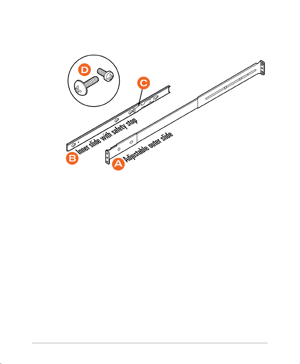
Figure 1. Rail assemblies and rail screws
Preparing to Set Up the SmartCell Gateway 200
Verifying the Package Contents
SmartCell Gateway 200 Getting Started Guide for SmartZone 3.5.1, 800-71517-001 Rev A 12
Page 13

Preparing to Set Up the SmartCell Gateway 200
Before You Begin
Before You Begin
Before installing and setting up the controller, Ruckus Wireless recommends that
you first complete the following pre-installation tasks.
Prepare the Required Hardware and Tools
You must supply the following tools and equipment:
• A switch or router with 10GbE interfaces (for connecting the controller to the
backbone network)
NOTE: A Fast Ethernet or Gigabit switch/router is required to upload management
data, cluster data, and configurations. A 10GBE switch/router is only required if the
customer is going to use tunnels.
• A Phillips #1 screwdriver
• A flat head screwdriver
• An administrative computer (desktop or laptop) running Windows 8/7/Vista/XP
or Mac OS X, containing a minimum RAM of 13G, with a web browser installed
(Google Chrome recommended). Supported web browsers include:
• Google Chrome 15 (and later)
• Safari 5.1.1 (and later)
• Mozilla Firefox 8 (and later)
• Microsoft Internet Explorer 9.0
• A grounded electrical power strip or surge suppressor to protect from circuit
overload
• A standard EIA 19-inch wide rack with an available 2RU space
• Two SFP+ modules (see Supported SFP+ Modules). For a redundant setup, you
will need four SFP+ modules.
NOTE: At the beginning of each procedure, this guide lists the specific tools,
accessories, or equipment that you will need to complete that procedure.
SmartCell Gateway 200 Getting Started Guide for SmartZone 3.5.1, 800-71517-001 Rev A 13
Page 14

Preparing to Set Up the SmartCell Gateway 200
1
2
3 4
Before You Begin
Get to Know the Physical Features of the Controller
The following sections identify the physical features of the controller that are relevant
to the installation and mounting instructions that this guide provides. Before you
begin the installation process, Ruckus Wireless strongly recommends that you
become familiar with these physical features.
Front Panel
Figure 2 shows the SCG front panel with the bezel installed. For descriptions of the
numbered parts, refer to Ta bl e 1 .
Figure 2. SCG front panel with the bezel
Table 1. SCG front panel parts
Number Description
1 Control panel (see Control Panel on the Front Panel)
2 RJ45 serial port (COM2/serial B). Use only the console cable provided to
connect this port via a laptop/notebook.
CAUTION! The SCG has two RJ45 serial ports – one on the front panel
and one on the rear panel. You can only use one of these two ports at any
given time. Using them simultaneously may cause both serial ports to
become unresponsive.
3 Use the USB port to connect a keyboard and mouse. Use a USB stick
(for a fresh installation).
4 Front bezel lock
SmartCell Gateway 200 Getting Started Guide for SmartZone 3.5.1, 800-71517-001 Rev A 14
Page 15

Preparing to Set Up the SmartCell Gateway 200
1
2 3
4
5
Before You Begin
Front Panel Without the Bezel
Figure 3 shows the front panel of the SCG without the bezel. For descriptions of the
numbered parts, refer to Ta bl e 2 .
Figure 3. SCG front panel without the bezel
Table 2. SCG front panel parts (without the bezel)
Number Description
1 ESD ground strap attachment
2 Hard drive bays (the SCG has two 600GB hard drives)
3 Control panel (buttons and status indicators, see Control Panel on the
Front Panel)
4 RJ45 serial port (COM2 / serial B). Use only the console cable provided to
connect this port to another device.
CAUTION! The SCG has two RJ45 serial ports – one on the front panel
and one on the rear panel. You can only use one of these two ports at any
given time. Using them simultaneously may cause both serial ports to
become unresponsive.
5 USB port (not used)
SmartCell Gateway 200 Getting Started Guide for SmartZone 3.5.1, 800-71517-001 Rev A 15
Page 16
Preparing to Set Up the SmartCell Gateway 200
12
11
10
9
8
7
1
2 3 4
5 6
Before You Begin
RJ45 Serial Port Pinouts
The following table shows the pinouts for the RJ45 serial ports on the front and rear
panels.
Table 3. RJ45 serial port pinouts
Pin Signal Name Description
1 SPB_RTS RTS (request to send)
2 SPB_DTR DTR (data terminal ready)
3 SPB_OUT_N TXD (transmit data)
4 GND Ground
5 SPB_RI RI (ring indicate)
6 SPB_SIN_N RXD (receive data)
7 SPB_DCR_DCD Data Set Ready/Data Carrier Detect
8 SPB_CTS CTS (clear to send)
Control Panel on the Front Panel
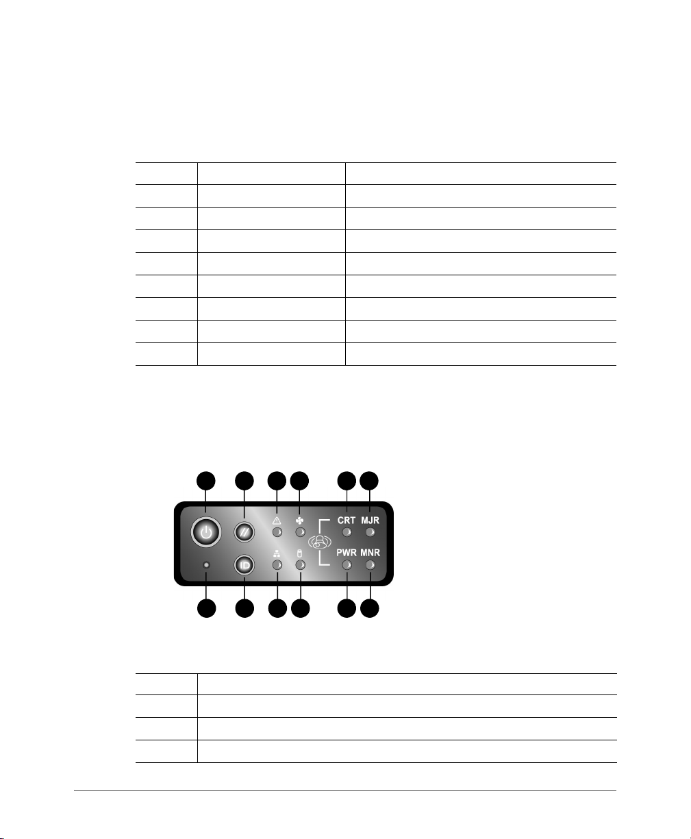
Figure 4 shows the control panel on the front panel of the SCG. For descriptions of
the numbered parts, refer to Tab le 4.
Figure 4. Control panel on the SCG front panel
Table 4. Control panel parts
SmartCell Gateway 200 Getting Started Guide for SmartZone 3.5.1, 800-71517-001 Rev A 16
Number Description
1 Power button
2 System reset button
3 System status LED
Page 17
Preparing to Set Up the SmartCell Gateway 200
1
2
3
4
5
6
7
8 9 10 11
12
Before You Begin
Table 4. Control panel parts (Continued)
Number Description
4 Fan status LED
5 Critical alarm (not implemented in this release)
6 MJR alarm LED (not implemented in this release)
7 NMI pin hole button (factory reset button)
8 Chassis ID button
9 NIC1/NIC2 activity LED
10 HDD activity LED (flashing green: HDD activity; amber: HDD fault; off: no
access or no HDD fault)
11 PWR alarm LED (not implemented in this release)
12 Minor alarm (amber: system unavailable; off: system available)
Rear Panel
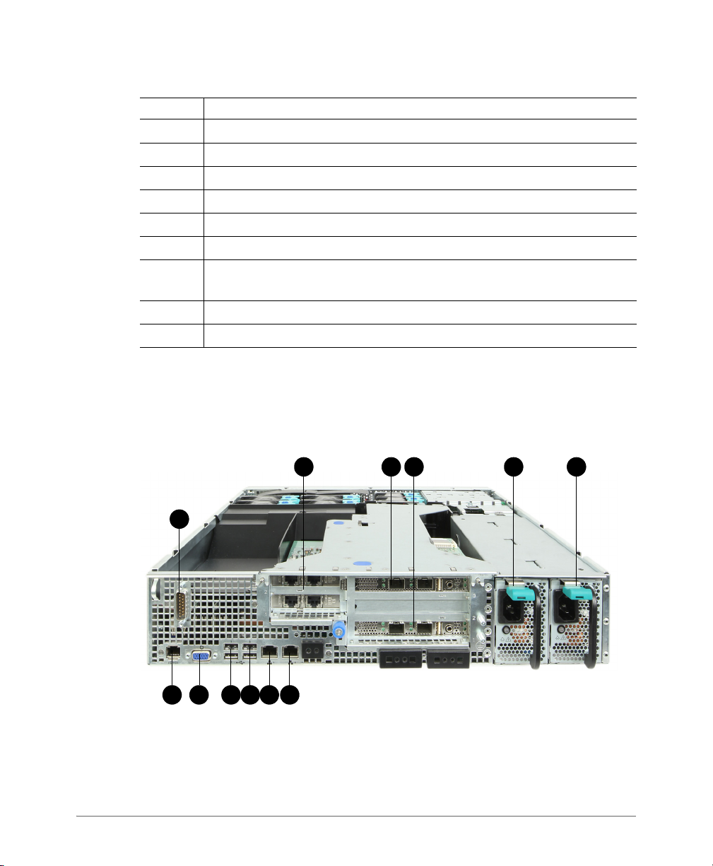
Figure 5 shows the rear panel of the SCG. For descriptions of the numbered parts,
refer to Ta b le 5 .
Figure 5. SCG rear panel
SmartCell Gateway 200 Getting Started Guide for SmartZone 3.5.1, 800-71517-001 Rev A 17
Page 18

Preparing to Set Up the SmartCell Gateway 200
Before You Begin
NOTE: The power supply locations (numbers 5 and 6) are for AC or DC power. AC
power supply is pictured.
Table 5. SCG rear panel parts
Number Description
1 Cable connector
2 Two low-profile PCIe interface cards that include four ports – one for
management traffic and three for redundancy. See Redundant Interfaces
on the SCG.
3 PCIe add-in card slot for DataPlane1
4 PCIe add-in card slot for DataPlane0
5 Power supply 2
6 Power supply 1
7 RJ45 serial port (COM2/serial B). Use only the console cable provided to
connect this port to another device.
CAUTION! The SCG has two RJ45 serial ports – one on the front panel
and one on the rear panel. You can only use one of these two ports at any
given time. Using them simultaneously may cause both serial ports to
become unresponsive.
NOTE: For information on how to access and use the SCG command line
interface, refer to the Command Line Interface Reference Guide.
8 Video connector
9 USB 0 and 1 (#1 on top)
10 USB 2 and 3 (#3 on top)
11 ETH0 GbE NIC for control (between access points and the SCG controller)
traffic
12 ETH1 GbE NIC for cluster traffic
SmartCell Gateway 200 Getting Started Guide for SmartZone 3.5.1, 800-71517-001 Rev A 18
Page 19

Preparing to Set Up the SmartCell Gateway 200
Before You Begin
NIC LEDs on the Rear Panel
Tab le 6 describes the behavior of the NIC LEDs on the rear panel of the SCG.
Table 6. LEDs on the SCG rear panel
LED Color LED State NIC State
Green/amber (left) Off 10Mbps
Green 100Mbps
Amber 1000Mbps
Green (right) On Active connection
Blinking Transmitting or receiving data
SmartCell Gateway 200 Getting Started Guide for SmartZone 3.5.1, 800-71517-001 Rev A 19
Page 20
Preparing to Set Up the SmartCell Gateway 200
ETH2
ETH3
ETH4
ETH5
ETH1
ETH0
Before You Begin
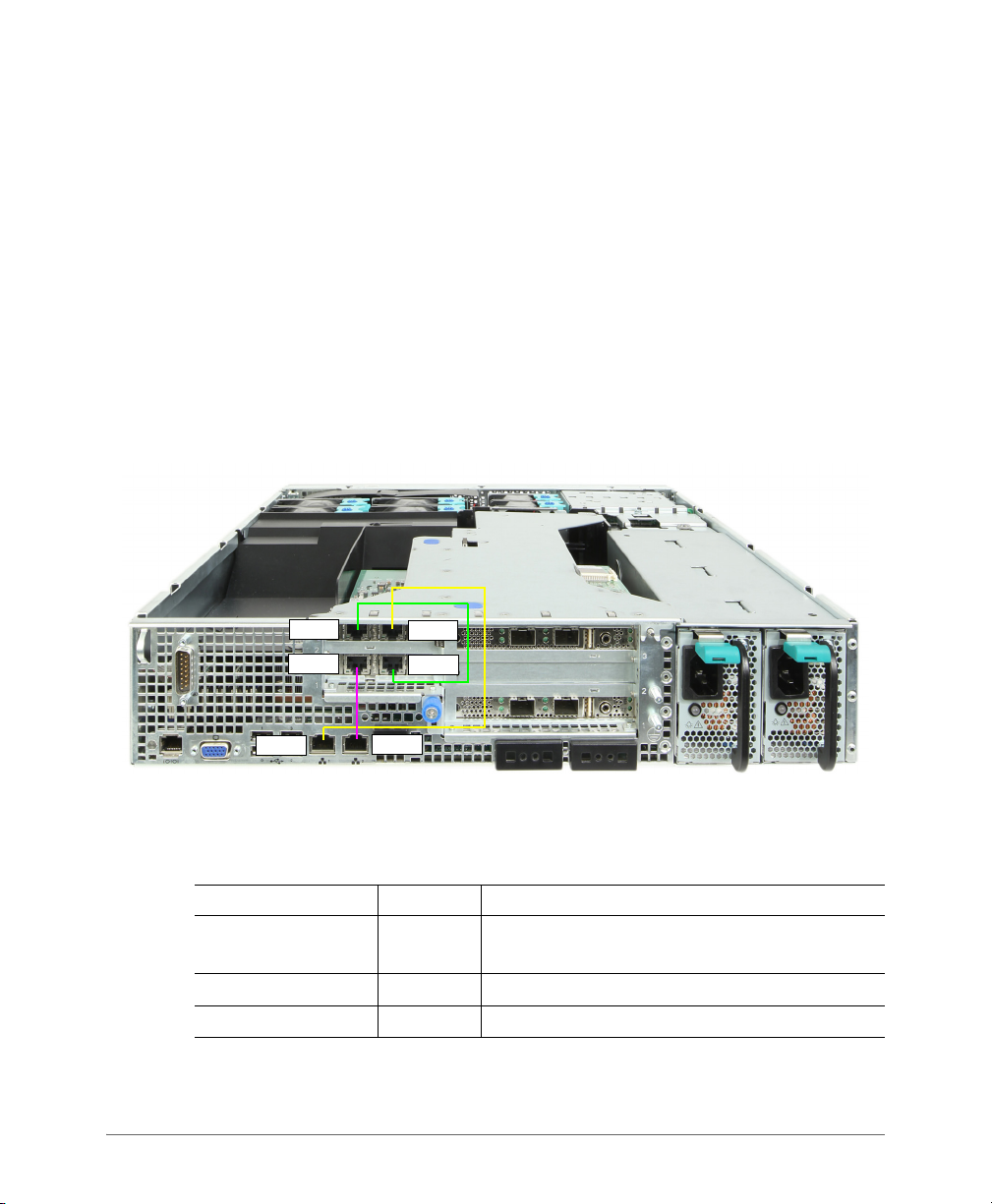
Redundant Interfaces on the SCG
The SCG offers network redundancy options by providing redundant interfaces for
the three traffic types that it handles – control traffic, cluster traffic, and management
traffic. A redundant interface pairs an active interface and a standby interface. When
the active interface fails, the standby interface becomes active automatically and
takes over the job of passing traffic.
To enable a redundant interfaces pair, you need to connect the member ports
(see Ta b le 7 ) to the same router or switch or to two different routers or switches,
depending on the network environment of your organization.
Figure 6 identifies the redundant interface pairs on the rear panel of the SCG and
Tab le 7 lists the member ports of each redundant interface pair.
Figure 6. Redundant interfaces on the SCG
Table 7. Bridge groups, member interfaces, and traffic types
Member Ports Bridge Traffic Type
ETH0 and ETH3 Bridge 0 Control (SSH tunnels between APs and SCG)
traffic
ETH1 and ETH4 Bridge 1 Cluster traffic
ETH2 and ETH5 Bridge 2 Management (web interface) traffic
SmartCell Gateway 200 Getting Started Guide for SmartZone 3.5.1, 800-71517-001 Rev A 20
Page 21

Mounting and Powering the SCG
In this chapter:
• Mounting the SCG onto a Server Rack
• What You Will Need
• Step 1: Unpack the Rack Mount Kit
• Step 2: Separate the Slide Rails into the Inner and Outer Parts
• Step 3: Install the Outer Rail Slides to the Rack Posts
• Step 4: Fasten the Shoulder Screws to the Server
• Step 5: Install the Inner Rails on the Server
• Step 6: Fasten the Inner Rails to the Server
• Step 7: Attach the Mounting Ears to the Rail Assembly
• Step 8: Slide the Rail Assembly into the Outer Rails and Secure to the Rack
• Powering On the SCG
2
SmartCell Gateway 200 Getting Started Guide for SmartZone 3.5.1, 800-71517-001 Rev A 21
Page 22

Mounting and Powering the SCG
Mounting the SCG onto a Server Rack
Mounting the SCG onto a Server Rack
The SCG is a 2U form factor server designed for mounting onto a standard EIA 19”
server rack. The supplied mounting hardware supports mounting on server racks
that are 22.5” to 32.5” deep. For racks of depth less than 22.5”, use the TMLCMOUNT21 rack mount kit (available at Avnet and manufactured by Kontron).
Before installing the SCG appliance onto a server rack, verify that all package
contents (see Unpacking the Controller) are included and ensure that you have
prepared all the required hardware and tools.
What You Will Need
• 3/8-inch hex driver or wrench
• Phillips (crosshead) screwdriver, #1 and #2 bits
• Anti-static wrist strap and conductive foam pad (recommended)
Step 1: Unpack the Rack Mount Kit
Refer to Rack Mount Kit Contents and verify that the rack mount kit contents are
complete.
SmartCell Gateway 200 Getting Started Guide for SmartZone 3.5.1, 800-71517-001 Rev A 22
Page 23
Mounting and Powering the SCG
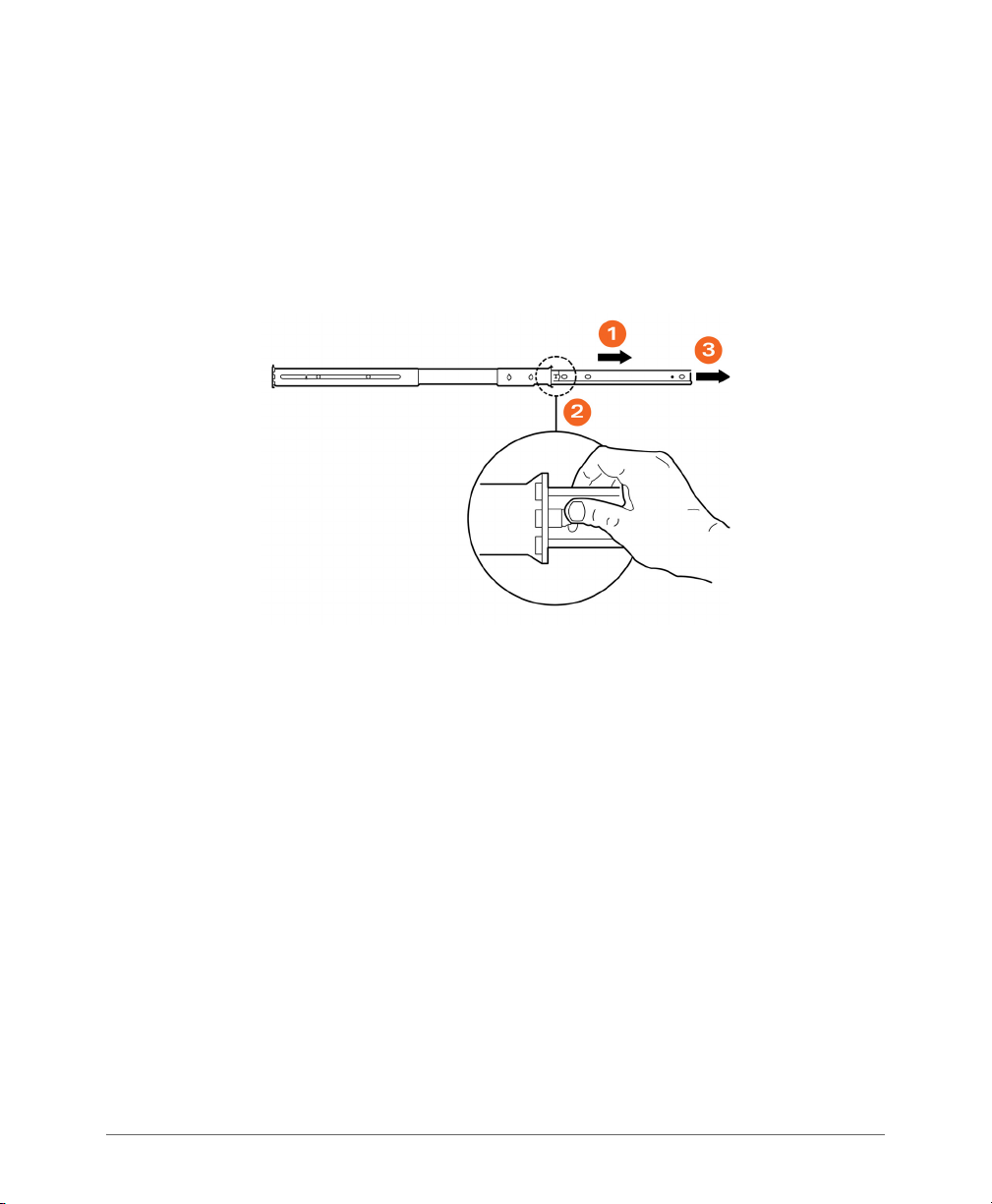
Step 2: Separate the Slide Rails into the Inner and Outer Parts
Step 2: Separate the Slide Rails into the Inner
and Outer Parts
1 Extend the inner rail (see 1 in Figure 7) until it locks.
2 Press down the spring safety lock (see 2 in Figure 7) to release the inner rail.
3 Remove the inner rail from the rail assembly (see 3 in Figure 7).
Figure 7. Separating the slide rails
SmartCell Gateway 200 Getting Started Guide for SmartZone 3.5.1, 800-71517-001 Rev A 23
Page 24

Mounting and Powering the SCG
Step 3: Install the Outer Rail Slides to the Rack Posts
Step 3: Install the Outer Rail Slides to the Rack
Posts
NOTE: The two rail assemblies are NOT interchangeable. Each assembly needs to
be installed into the rack by its orientation (right or left) when standing in front of the
rack. The right rail assembly is identified with a BLUE sticker and the left rail assembly
is identified with a GREEN sticker.
Attach the outer rail slides to the rack posts using two #8-32 x 1/2 screws at the
front posts and two #8-32 x 1/2 screws at the rear posts.
Figure 8. Installing the outer rails
SmartCell Gateway 200 Getting Started Guide for SmartZone 3.5.1, 800-71517-001 Rev A 24
Page 25
Mounting and Powering the SCG
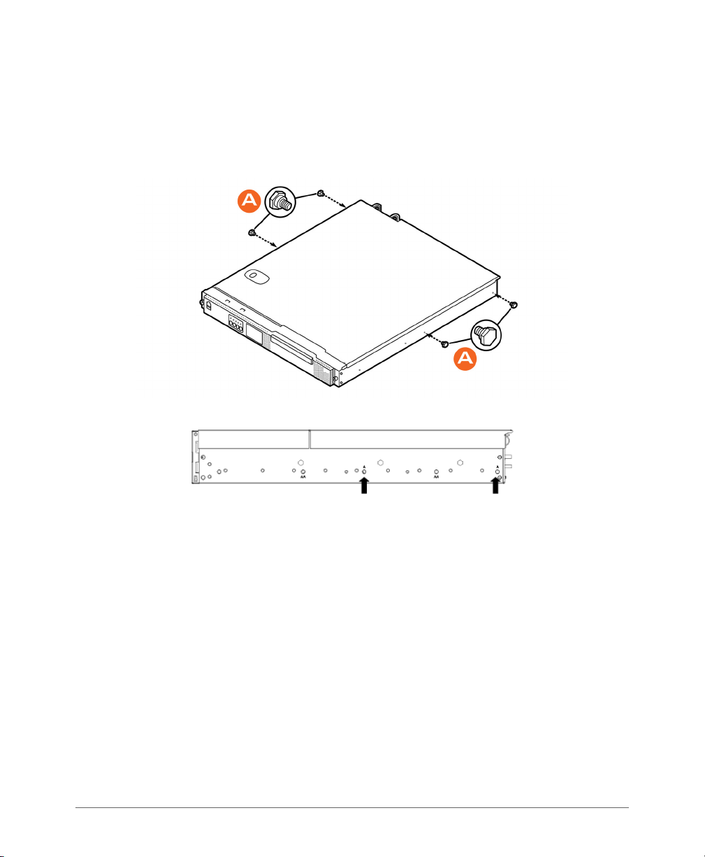
Step 4: Fasten the Shoulder Screws to the Server
Step 4: Fasten the Shoulder Screws to the
Server
Fasten two hex head shoulder screws on each side of the server.
Figure 9. Fastening the shoulder screws
SmartCell Gateway 200 Getting Started Guide for SmartZone 3.5.1, 800-71517-001 Rev A 25
Page 26

Mounting and Powering the SCG
Step 5: Install the Inner Rails on the Server
Step 5: Install the Inner Rails on the Server
Install the inner rails onto the hex head shoulder screws, and then slide the inner
rails forward.
Figure 10. Installing the inner rails
Step 6: Fasten the Inner Rails to the Server
Secure the inner rails with one #6-32 x 1/4 screw for each rail.
Figure 11. Securing the inner rails
SmartCell Gateway 200 Getting Started Guide for SmartZone 3.5.1, 800-71517-001 Rev A 26
Page 27

Mounting and Powering the SCG
Step 7: Attach the Mounting Ears to the Rail Assembly
Step 7: Attach the Mounting Ears to the Rail
Assembly
Attach the rack mounting ears (A) to each side of the server using the #10-32 x 3/
8 screws (B).
Figure 12. Attaching the mounting ears
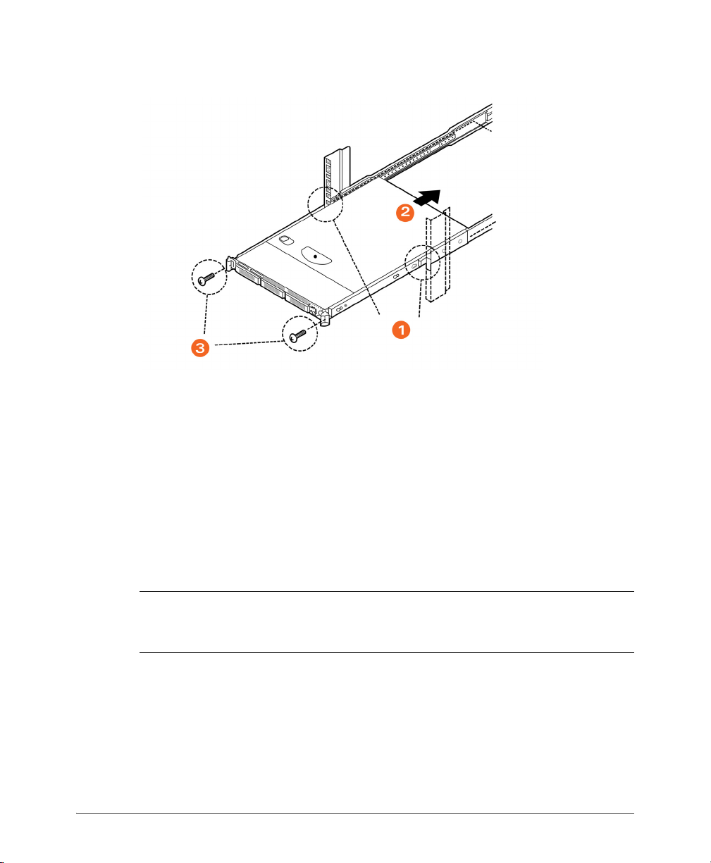
Step 8: Slide the Rail Assembly into the Outer Rails and Secure to the Rack
WARNING! The controller is heavy (40 lbs/18.14kg). Two people should work
together to lift and slide the appliance into the rack. Ruckus Wireless strongly
recommends against one person attempting to perform this task alone.
1 Align the inner rails (attached to the server chassis) with the outer rail assemblies
(attached to the rack).
2 Engage the matching rails, and then slide the server chassis into the rack until
the two spring safety locks snap into position.
3 Press down the two spring safety locks (one on each side). See 1 in Figure 13.
4 Slide the server chassis all the way into the rack. See 2 in Figure 13.
5 Use the rack screws (#8-32 x 3/4) to secure the chassis and rack handles into
the rack. See 3 in Figure 13.
SmartCell Gateway 200 Getting Started Guide for SmartZone 3.5.1, 800-71517-001 Rev A 27
Page 28
Mounting and Powering the SCG
Powering On the SCG
Figure 13. Securing the server to the rack
Congratulations! You have completed mounting the SCG onto your server rack.
Powering On the SCG
The SCG supports both AC and DC power. Refer to the relevant section below for
instructions on how to power on the SCG.
• Using AC Power
• Using DC Power
Using AC Power
NOTE: The AC power cable (part number 902-0174-XX00, where XX is the two-
character country code) is not supplied with the SCG appliance and may be ordered
separately.
Follow these steps to use AC to supply power to the SCG.
1 Connect the AC power cable to the primary power socket (right) on the rear
panel. Optionally, connect a second AC power cable to the backup power socket
(left) on the rear panel.
SmartCell Gateway 200 Getting Started Guide for SmartZone 3.5.1, 800-71517-001 Rev A 28
Page 29

Mounting and Powering the SCG
Primary power
Backup power
Power button
Powering On the SCG
Figure 14. Power sockets on the SCG
2 Connect the other end of the power cable (or cables) to an electrical outlet.
3 Press the Power button on the control panel to power on the SCG. The MNR
LED on the Control Panel turns amber while booting up, and turns off when the
startup is complete.
Figure 15. Power button on the Control Panel
SmartCell Gateway 200 Getting Started Guide for SmartZone 3.5.1, 800-71517-001 Rev A 29
Page 30
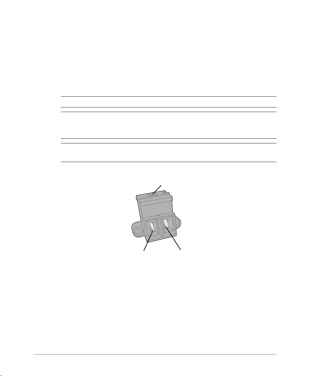
Mounting and Powering the SCG
Screw cover
–+
Powering On the SCG
Using DC Power
The DC power subsystem supports up to two redundant DC power supply units
(PSUs). To remove the PSU, simply press down on the green locking tab while
pulling outward on the PSU handle. To insert the PSU, slide the entire unit (green
locking tab toward the top) fully into the SCG chassis until it locks in place.
If using D C power, connect -4 8V DC input power to the PSU. The DC input polarity
is marked on the DC PSU case. In Figure 16, “-” is on the left and “+” is on the right.
NOTE: Use #14-#10 AWG to the DC input connector.
CAUTION! To avoid the potential for electrical shock and fire hazard, ensure that
the DC wiring to the DC input connectors has adequate circuit protection in
accordance with local electrical codes
NOTE: Information on how to replace the PSU is provided in the SmartCell Gateway
200 Administrator Guide.
Figure 16. DC input connector
Follow these steps to use DC to supply power to the SCG.
1 (When looking at the DC input connector from the angle shown above), slide the
screw cover on the top of the DC input connector to the left to reveal the top
screws.
2 Loosen the screws enough so that the DC input wires can be fully inserted into
the apertures.
3 Insert the “-” wire into the left side aperture, and the “+” wire into the right side.
4 Screw the top screws down until the wires are locked in place.
SmartCell Gateway 200 Getting Started Guide for SmartZone 3.5.1, 800-71517-001 Rev A 30
Page 31

Mounting and Powering the SCG
Powering On the SCG
5 Slide the screw cover back to the right.
6 Apply power to the DC input system. The single LED on the bottom left side of
the power supply module lights green when all power outputs are available.
You have completed supplying power to the SCG using DC.
DC Power Supply Input Voltage and Current Requirements
Tab le 8 lists the DC power supply input voltage and current requirements.
Table 8. DC input voltage and current requirements
DC Input Voltage
Nominal -48Vdc
Minimum -38Vdc
Rated -48Vdc to -60Vdc
Maximum -75Vdc
DC Input Current
Maximum 13A @ -38Vdc
CAUTION! To avoid the potential for an electrical shock hazard, for AC power you
must include a third wire safety ground conductor with the rack installation. For DC
power, the two studs for chassis enclosure grounding must be used for proper safety
grounding. With AC power, if the server power cord is plugged into an outlet that is
part of the rack, then you must provide proper grounding for the rack itself. If the
server power cord is plugged into a wall outlet, the safety ground conductor in the
power cord provides proper grounding only for the server. You must provide
additional, proper grounding for the rack and other devices installed in it.
SmartCell Gateway 200 Getting Started Guide for SmartZone 3.5.1, 800-71517-001 Rev A 31
Page 32

Mounting and Powering the SCG
Powering On the SCG
DC PSU LED
Tab le 9 describes the behavior of the DC PSU LED.
Table 9. DC PSU LED behavior
LED State Description
Off No DC to all power supplies
Amber • No DC to this PSU only (for 1+1 configuration), or;
• Power supply critical event causing a shutdown: failure, fuse
blown (1+1 only), OCP (12V), OVP (12V), fan failed
Blinking Amber Power supply warning events where power supply continues to
operate: high temp, high power/high current, slow fan
Blinking Green DC present / Only 5Vsb on (PS off)
Green Output ON and OK
SmartCell Gateway 200 Getting Started Guide for SmartZone 3.5.1, 800-71517-001 Rev A 32
Page 33

Preparing the Interface Settings and Administrative Computer
In this chapter:
• Preparing the SCG Interface Settings to Use
• Preparing the Administrative Computer
3
SmartCell Gateway 200 Getting Started Guide for SmartZone 3.5.1, 800-71517-001 Rev A 33
Page 34

Preparing the Interface Settings and Administrative Computer
Preparing the SCG Interface Settings to Use
Preparing the SCG Interface Settings to Use
The SCG appliance includes three network interfaces (see Ta bl e 10 ) that need to
be connected to the network for the appliance to work. When you run the SCG
Setup Wizard later in this chapter, you will be required to assign each of these
interfaces on the SCG a separate set of network settings.
CAUTION! When you run the Setup Wizard, you must configure the three SCG
interfaces to be on three different subnets. Failure to do so may result in loss of
access to the web interface or failure of system functions and services.
The following network settings are required:
• IP address: IP address in IPv4. If your network uses IPv6, see IPv6 Address
Configuration for more information.
•Netmask
• Gateway
• Primary DNS server
• Secondary DNS server
Table 10. SCG interfaces
Interface Description
AP/DataPlane Used for AP configuration and client traffic
Cluster Used for cluster traffic
Management (Web) Used for management traffic. The IP address that you assign
to this interface will be the IP address through which you can
access the SCG via SSH or Web GUI.
IPv6 Address Configuration
The controller supports IPv4 and dual IPv4/IPv6 operation modes. If both IPv4 and
IPv6 are used on the network, the controller will keep both IP addresses. APs can
be in V4 or V6 or both based on the zone configuration. By default it will be in IPv4,
and if required you need to enable IPv6. Ruckus ZoneFlex APs operate in dual IPv4/
v6 mode by default, so you do not need to manually set the mode for each AP.
If you enable IPv6, you have the option to manually configure an IP address in IPv6
format (128 bits separated by colons, instead of decimals) or to choose Auto
Configuration. If you choose Manual, you will need to enter values for the IP
address, prefix length and gateway.
SmartCell Gateway 200 Getting Started Guide for SmartZone 3.5.1, 800-71517-001 Rev A 34
Page 35

Preparing the Interface Settings and Administrative Computer
Preparing the Administrative Computer
The DNS address can be configured manually or obtained automatically by the
DHCPv6 client.
Preparing the Administrative Computer
Follow these steps to prepare the administrative computer that you will use to run
the SCG Setup Wizard.
1 On the administrative computer, open the Network Connections (or Network and
Dial-up Connections) control panel according to how your Start menu is set up:
• Start > Settings > Network Connections
• Start > Control Panel > Network and Sharing Center > Change Adapter
Settings
NOTE: This procedure assumes Windows 7 as the operating system. Procedures
for other operating systems are similar.
2 When the Network Connections windows appears, right click the icon for “Local
Area Connection” and click Properties.
3 When the Local Area Connection Properties dialog box appears, click Internet
Protocol Version 4 (TCP/IPv4) from the scrolling list, then and click Properties.
The TCP/IP Properties dialog box appears.
NOTE: Write down all of the currently active settings so you can restore your
computer to its current configuration later (when this process is complete).
SmartCell Gateway 200 Getting Started Guide for SmartZone 3.5.1, 800-71517-001 Rev A 35
Page 36

Preparing the Interface Settings and Administrative Computer
Preparing the Administrative Computer
Figure 17. The Internet Protocol Version 4 (TCP/IP) properties dialog box
4 Select Use the following IP address (if it is not already active) and make the
following entries:
• IP address: 192.168.2.13 (or any address on the 192.168.2.x network other
than 192.168.2.2, which is in use by the SCG)
• Subnet mask: 255.255.255.0
• Default gateway: 192.168.2.2
• Preferred DNS server: 192.168.2.2
5 Leave the Alternate DNS Server field empty.
6 Click OK to save your changes and exit first the TCP/IP Properties dialog box,
then the Local Area Connection Properties dialog box. Your changes are put into
effect immediately.
You have completed preparing the administrative computer.
SmartCell Gateway 200 Getting Started Guide for SmartZone 3.5.1, 800-71517-001 Rev A 36
Page 37

Running the Setup Wizard and Logging On to the Web Interface
In this chapter:
• Overview of the SCG Setup Wizard
• Step 1: Start the Setup Wizard and Set the Language
• Step 2: Configure the Management IP Address Settings
• Step 4: Configure the Cluster Settings
• Step 5: Verify the Settings
• Connecting Data Blades to the Network
• Logging On to the Web Interface
4
SmartCell Gateway 200 Getting Started Guide for SmartZone 3.5.1, 800-71517-001 Rev A 37
Page 38

Running the Setup Wizard and Logging On to the Web Interface
ETH2
Overview of the SCG Setup Wizard
Overview of the SCG Setup Wizard
Follow these steps to run and complete the SCG Setup Wizard.
Step 1: Start the Setup Wizard and Set the Language
Step 2: Configure the Management IP Address Settings
Step 3: Configure the Data Plane IP Address Settings
Step 4: Configure the Cluster Settings
Step 5: Verify the Settings
Step 1: Start the Setup Wizard and Set the
Language
1 Connect one end of an Ethernet cable to ETH2 on the rear panel of the SCG,
and then connect the other end to an Ethernet port on the administrative
computer.
Figure 18. Location of ETH2
2 Start your web browser, and then enter the following in the address bar:
http://192.168.2.2:8443
The SCG Setup Wizard appears, displaying the Language page.
SmartCell Gateway 200 Getting Started Guide for SmartZone 3.5.1, 800-71517-001 Rev A 38
Page 39

Running the Setup Wizard and Logging On to the Web Interface
Step 1: Start the Setup Wizard and Set the Language
Figure 19. The Language page
3 Select your preferred language for the SCG web interface. Available options
include:
•English
• Traditional Chinese
• Simplified Chinese
4 Click Next. The Management IP page appears and displays options for
configuring the network addressing of the following interfaces on the controller:
• Control (AP/DataPlane)
•Cluster
• Management (Web)
SmartCell Gateway 200 Getting Started Guide for SmartZone 3.5.1, 800-71517-001 Rev A 39
Page 40

Running the Setup Wizard and Logging On to the Web Interface
Step 1: Start the Setup Wizard and Set the Language
Figure 20. The Management IP page, showing the Control (AP/DataPlane) tab
SmartCell Gateway 200 Getting Started Guide for SmartZone 3.5.1, 800-71517-001 Rev A 40
Page 41

Running the Setup Wizard and Logging On to the Web Interface
Step 2: Configure the Management IP Address Settings
Step 2: Configure the Management IP
Address Settings
1 In IP Version Support, select one of the following options:
• IPv4 Only: Click this option if you want the controller to obtain an IPv4
address from a DHCP server on the network.
• IPv4 and IPv6: Click this option if you want the controller to obtain both IPv4
and IPv6 addresses from DHCP and DHCPv6 servers on the network.
2 Configure the IP address settings of the Control (AP/DataPlane) interface.
a Under the IPv4 section, click Static, and then enter the network settings that
you want to assign to the AP/DataPlane interface, through which client traffic
and configuration data are sent and received.
NOTE: Although it is possible to use DHCP to assign IP address settings to the
Control interface automatically, Ruckus Wireless strongly recommends assigning a
static IP address to this interface.
WARNING! You must configure the three interfaces to be on three different
subnets. Failure to do so may result in loss of access to the web interface or failure
of system functions and services.
The following network settings are required (others are optional):
- IP address
-Netmask
- Default gateway
b If you clicked IPv4 and IPv6 at the beginning of this procedure, under the
IPv6 section, click Auto Configuration if you want the controller to obtain its
IP address from Router Advertisements (RAs) or from a DHCPv6 server on
the network. If you want to manually assign the IPv6 network address, click
Static, and then set the values for the following:
- IP address (IPv6): Enter an IPv6 address (global only) with a prefix length
(for example, 1234::5678:0:C12/123). Link-local addresses are
unsupported.
- Gateway: Enter an IPv6 address (global or link-local) without a prefix
length. Here are examples:
• Global address without a prefix length: 1234::5678:0:C12
• Link-local address without a prefix length: fe80::5678:0:C12
SmartCell Gateway 200 Getting Started Guide for SmartZone 3.5.1, 800-71517-001 Rev A 41
Page 42

Running the Setup Wizard and Logging On to the Web Interface
Step 2: Configure the Management IP Address Settings
c Click the Cluster tab when done.
Figure 21. The Cluster tab
3 On the Cluster tab, click Static under the IPv4 section, and then enter the
network settings that you want to assign to the cluster interface, through which
cluster data will be sent and received.
NOTE: Although it is possible to use DHCP to assign IP address settings to the
Cluster interface automatically, Ruckus Wireless strongly recommends assigning a
static IP address to this interface.
WARNING! You must configure the three SCG interfaces to be on three different
subnets. Failure to do so may result in loss of access to the web interface or failure
of system functions and services.
The following network settings are required (others are optional):
• IP address
•Netmask
• Default gateway
Click the Management (Web) tab when done.
SmartCell Gateway 200 Getting Started Guide for SmartZone 3.5.1, 800-71517-001 Rev A 42
Page 43

Running the Setup Wizard and Logging On to the Web Interface
Step 2: Configure the Management IP Address Settings
Figure 22. The Management (Web) tab
4 On the Management (Web) tab, configure the IP address settings of the
management interface.
a Under the IPv4 section, click Static, and then enter the network settings that
you want to assign to the AP/DataPlane interface, through which client traffic
and configuration data are sent and received.
NOTE: Although it is possible to use DHCP to assign IP address settings to the
Control interface automatically, Ruckus Wireless strongly recommends assigning a
static IP address to this interface.
WARNING! You must configure the three interfaces to be on three different
subnets. Failure to do so may result in loss of access to the web interface or failure
of system functions and services.
The following network settings are required (others are optional):
- IP address
-Netmask
- Default gateway
SmartCell Gateway 200 Getting Started Guide for SmartZone 3.5.1, 800-71517-001 Rev A 43
Page 44

Running the Setup Wizard and Logging On to the Web Interface
Step 2: Configure the Management IP Address Settings
b If you clicked IPv4 and IPv6 at the beginning of this procedure, under the
IPv6 section, click Auto Configuration if you want the management (web)
interface to obtain its IP address from Router Advertisements (RAs) or from
a DHCPv6 server on the network. If you want to manually assign the IPv6
network address, click Static, and then set the values for the following:
- IP address (IPv6): Enter an IPv6 address (global only) with a prefix length
(for example, 1234::5678:0:C12/123). Link-local addresses are
unsupported.
- Gateway: Enter an IPv6 address (global or link-local) without a prefix
length. Here are examples:
• Global address without a prefix length: 1234::5678:0:C12
• Link-local address without a prefix length: fe80::5678:0:C12
5 At the bottom of the screen (see Figure 23), select the interface that you want
to set as the default system gateways for IPv4 and IPv6 (if enabled), and then
type the primary and secondary DNS server addresses.
NOTE: The appropriate interface to use as the default system gateway depends
on the topology of your network. See Important Notes About Selecting the System
Default Gateway for more information.
Figure 23. Select the IPv4 (and IPv6, if enabled) default system gateway
SmartCell Gateway 200 Getting Started Guide for SmartZone 3.5.1, 800-71517-001 Rev A 44
Page 45

Running the Setup Wizard and Logging On to the Web Interface
Step 2: Configure the Management IP Address Settings
6 Check the network settings that you have configured on the Control, Cluster,
and Management tabs and the default gateway that you have selected. Verify
that they are all correct.
7 Click the Apply to continue. The controller validates and applies the network
settings that you have configured.
Figure 24. The controller validates and applies the network settings you have configured
CAUTION! It may take the controller up to 15 minutes to activate its interfaces. If
an error message appears after you apply the network interface settings, wait at
least 15 minutes, and then try again.
NOTE: If the controller is unable to validate the network settings that you configured,
an error message appears. If this happens, check the network settings that you
configured and verify that you are able to connect to the IP address that you assigned
to the Management (Web) interface.
8 Update the IP address settings of the administrative computer with the same
subnet settings that you assigned to the Management (Web) interface
(see Step 4).
Continue to Step 3: Configure the Data Plane IP Address Settings.
SmartCell Gateway 200 Getting Started Guide for SmartZone 3.5.1, 800-71517-001 Rev A 45
Page 46

Running the Setup Wizard and Logging On to the Web Interface
Step 2: Configure the Management IP Address Settings
Important Notes About Selecting the System Default Gateway
Depending on your network topology, you may select either the Management or
Control interface as the system default gateway.
• If all of the managed APs are located in different locations on the Internet, the
controller may not know all of the IP subnets of these APs. In this case, the
control interface should be set as the default system gateway of the controller
and you will need to add a static route to reach the management network.
• If all of the managed APs belong to a single subnet or to multiple subnets on
which you can set the route statically, then you can set the management interface
as the default gateway users can set default system gateway of the controller
and set static routes for the controller to reach all of its managed APs.
SmartCell Gateway 200 Getting Started Guide for SmartZone 3.5.1, 800-71517-001 Rev A 46
Page 47

Running the Setup Wizard and Logging On to the Web Interface
Step 3: Configure the Data Plane IP Address Settings
Step 3: Configure the Data Plane IP Address
Settings
1 On the DataPlane0 and DataPlane1 tab, configure the IP address settings of
DataPlane0 and DataPlane1, respectively.
NOTE: Although it is possible to use DHCP to assign IP address settings to the
data plane interfaces automatically, Ruckus Wireless strongly recommends
assigning static IP address to these interfaces.
The following network settings are required:
• IP address
•Netmask
• Default gateway
Figure 25. The DataPlane IP page
2 Click Next to continue. The Cluster Information page appears.
SmartCell Gateway 200 Getting Started Guide for SmartZone 3.5.1, 800-71517-001 Rev A 47
Page 48

Running the Setup Wizard and Logging On to the Web Interface
Step 4: Configure the Cluster Settings
Step 4: Configure the Cluster Settings
The actions that you need to perform in this step depends on whether you are
creating a new cluster (with this controller as the first node) or you are setting up
this controller to join an existing cluster.
• If This Controller Is Forming a New Cluster
• If This Controller Is Joining an Existing Cluster
NOTE: A SmartCell Gateway (SCG) 200 unit can only form a cluster with other
SmartCell Gateway 200 units. It cannot join a cluster of SmartZone (SZ) 100 units
(and vice versa).
Figure 26. The Cluster Information page
SmartCell Gateway 200 Getting Started Guide for SmartZone 3.5.1, 800-71517-001 Rev A 48
Page 49

Running the Setup Wizard and Logging On to the Web Interface
Step 4: Configure the Cluster Settings
If This Controller Is Forming a New Cluster
Follow these steps if you want to use this controller to create a new cluster.
1 On the Cluster Information page, configure the following settings:
• Cluster Setting: Select New Cluster.
• Cluster Name: Type a name that you want to assign to this new cluster.
• Controller Name: Type a name for the controller in this new cluster. The
Controller/Node name can be different for each.
• Controller Description: Type a description for the controller.
• NTP Server: Type the address of the NTP server from which members of the
cluster will obtain and synchronize time. The default NTP server is
pool.ntp.org.
• AP Conversion: Select the check box if you want ZoneFlex APs that are in
factory default settings to be converted to SmartZone APs automatically
when they are connected to the same subnet as the controller.
CAUTION! Before continuing, verify that the cluster settings are correct. Once the
cluster is created, you will be unable to edit its settings without rebuilding the cluster
from scratch.
2 Click Next to continue to the next Setup Wizard page. The Administrator page
appears.
3 On the Administrator page, configure the web interface and CLI passwords. All
fields are required.
• Admin Password: Type a password that you want to use to access the web
interface.
• Confirm Password: Retype the password above to confirm.
• Enable Password: Type a password that you want to use to enable CLI
access to the controller.
• Confirm Password: Retype the password above to confirm.
4 Click Next to continue. The Confirmation page appears and displays all the
controller settings that you have configured using the Setup Wizard.
Continue to Step 5: Verify the Settings.
SmartCell Gateway 200 Getting Started Guide for SmartZone 3.5.1, 800-71517-001 Rev A 49
Page 50

Running the Setup Wizard and Logging On to the Web Interface
Step 4: Configure the Cluster Settings
Figure 27. Set the web interface and command line interface passwords
SmartCell Gateway 200 Getting Started Guide for SmartZone 3.5.1, 800-71517-001 Rev A 50
Page 51

Running the Setup Wizard and Logging On to the Web Interface
Step 4: Configure the Cluster Settings
If This Controller Is Joining an Existing Cluster
If this is not the first cluster on the network, you can set up this controller to join an
existing cluster.
CAUTION! To add this controller to an existing cluster, the entire target cluster must
be in a healthy state (no node must be in “out of service” state). If any member node
is out of service, the join request will fail. You will need to remove any out-of-service
node from the cluster before you can add a new node successfully.
Follow these steps to configure this controller to join an existing cluster.
1 Click the Scan button to display a list of existing clusters that this controller can
join.
NOTE: The cluster discovery mechanism of the controller uses UDP port 7500. If
a cluster exists on the network but the cluster list remains empty after the scan,
verify that the switch to which the controller is connected does not block UDP
packets and that UDP port 7500 is open on the switch.
2 When the list of clusters appears, click a cluster name to join. The Cluster Setting
value changes to Join Exist cluster, and then the Cluster Name and Join Exist
SCG Cluster IP boxes are populated with values from the cluster that this
controller is joining. If you know the correct cluster name, you can specify the
name to join.
3 Assign a name and description to this controller by filling out the Controller Name
and Controller Description boxes.
4 Click Next.
NOTE: If the firmware version on this controller (shown on the lower left area of the
Cluster Information page) does not match the firmware version of the cluster, a
message appears and prompts you to upgrade the controller firmware. Click
Upgrade, and then follow the prompts to upgrade the controller to the firmware
version of the cluster.
SmartCell Gateway 200 Getting Started Guide for SmartZone 3.5.1, 800-71517-001 Rev A 51
Page 52

Running the Setup Wizard and Logging On to the Web Interface
Step 5: Verify the Settings
Step 5: Verify the Settings
Verify that all the settings displayed on the Confirmation page are correct. If they
are all correct, click Finish to apply the settings and activate the SCG on the
network.
Figure 28. Verify that the settings displayed on the Confirmation page are correct
NOTE: If you find an incorrect setting, click the Back button until you reach the
related page, and then edit the settings. When you finish editing the settings, click
the Next button until you reach the Confirmation page again.
A progress bar appears and displays the progress of applying the settings, starting
the SCG services, and activating the SCG on the network.
When the process is complete, the progress bar shows the message 100% Done.
The page also shows the IP address through which you can access the SCG web
interface to manage the controller.
Congratulations! You have completed the Setup Wizard. You are now ready to log
on to the controller’s web interface.
SmartCell Gateway 200 Getting Started Guide for SmartZone 3.5.1, 800-71517-001 Rev A 52
Page 53

Running the Setup Wizard and Logging On to the Web Interface
Connecting Data Blades to the Network
Connecting Data Blades to the Network
Follow these steps to connect the data blades to the network.
1 Connect ETH2 to the router or switch.
2 Obtain two optical fiber (MMF) cables (not supplied).
3 Take one optical fiber cable, and then connect one SFP port on DataPlane0 to
an SFP port on the 10GB router or switch.
4 Take the remaining optical fiber cable, and then connect one SFP port on
DataPlane1 to another SFP port on the router or switch.
NOTE: The dataplane interfaces do not support auto negotiation and must
therefore be connected to 10GB ports on a router or switch.
NOTE: For a list of SFP+ modules that the controller supports, see Supported SFP+
Modules.
5 Connect ETH1 to another router or switch to which other controllers (if present)
are connected.
NOTE: Depending on your network setup, you may also connect ETH1 to the same
router or switch to which ETH2 is connected.
Supported SFP+ Modules
Tab le 1 1 lists the SFP+ modules that the controller supports. For more information
about these modules, visit the manufacturer’s website.
Table 11. SFP+ modules supported by the SCG
Name Product Code Description
Intel Ethernet SFP+ SR (Short
Range) Optics
SmartCell Gateway 200 Getting Started Guide for SmartZone 3.5.1, 800-71517-001 Rev A 53
E10GSFPSR Dual Rate 10GBASE-SR/1000BASE-
SX with duplex LC connector
Page 54

Running the Setup Wizard and Logging On to the Web Interface
Logging On to the Web Interface
Logging On to the Web Interface
You can access the controller’s web interface from any computer that is on the
same subnet as the Management (Web) interface, which you configured in Step 2:
Configure the Management IP Address Settings.
Follow these steps to log on to the controller’s web interface.
1 On a computer that is on the same subnet as the Management (Web) interface,
start a web browser.
2 In the address bar, enter the IP address that you assigned to the Management
(Web) interface and append a colon and 8443 (controller’s management port
number) at the end of the address.
For example, if the IP address that you assigned to the Management (Web)
interface is 10.10.101.1, then you should enter:
https://10.10.101.1:8443
NOTE: While using HTTPS, as part of the security, the user is prompted to confirm
that the IP is safe to continue with.
The controller’s web interface logon page appears.
Figure 29. The controller’s web interface logon page
SmartCell Gateway 200 Getting Started Guide for SmartZone 3.5.1, 800-71517-001 Rev A 54
Page 55

Running the Setup Wizard and Logging On to the Web Interface
Logging On to the Web Interface
3 Log on to the controller’s web interface using the following logon details:
•User Name: admin
• Password: {the password that you set when you ran the SCG
Setup Wizard}
4 Click Log On.
The web interface refreshes, and then displays the Dashboard page, which indicates
that you have logged on successfully.
You are now ready to configure the controller.
SmartCell Gateway 200 Getting Started Guide for SmartZone 3.5.1, 800-71517-001 Rev A 55
Page 56

Configuring the SCG for the First Time
5
In this chapter:
• Creating an AP Zone
• Configuring AAA Servers and Hotspot Settings
• Creating a Registration Rule
• Defining the WLAN Settings of a Zone
• Verifying That Wireless Clients Can Associate with a Managed AP
• What to Do Next
SmartCell Gateway 200 Getting Started Guide for SmartZone 3.5.1, 800-71517-001 Rev A 56
Page 57

Configuring the SCG for the First Time
Creating an AP Zone
Creating an AP Zone
The first step in configuring the SCG is to create an AP zone. An AP zone functions
as a way of grouping APs and applying a particular set of settings (including WLANs
and their settings) to these groups of APs. Each AP zone can include up to six WLAN
services.
A zone called Staging Zone exists by default. Any AP that registers with the SCG
that is not assigned a specific zone is automatically assigned to the Staging Zone.
NOTE: Certain new features introduced in 3.5 are not compatible with the 3.4 AP
zones.
Follow these steps to create a new AP zone.
1 On the menu, click Access Points.
2 From the System tree, select the location where you want to create the zone (for
example, System or Domain), and then click .
3 Configure the zone by completing the settings listed in Ta bl e 1 2 below.
4 Click OK.
When the controller completes creating the zone, the page refreshes, and then the
zone you created appears in the Access Points tree.
You have completed creating your first AP zone. You can create additional AP zones,
if needed.
SmartCell Gateway 200 Getting Started Guide for SmartZone 3.5.1, 800-71517-001 Rev A 57
Page 58

Figure 30. Creating a new AP zone
Configuring the SCG for the First Time
Creating an AP Zone
Table 12. New zone settings
Field Description Your Action
Name Indicates the name of the zone/AP
Enter a name.
group.
Description Indicates the short description
Enter a brief description
assigned to the zone or AP group.
Type Indicates if you are creating a domain,
zone or an AP group.
Appears by default. You can also
choose the option.
Parent Group Indicates the parent AP group. Appears by default.
Configuration General > Options
SmartCell Gateway 200 Getting Started Guide for SmartZone 3.5.1, 800-71517-001 Rev A 58
Page 59

Configuring the SCG for the First Time
Creating an AP Zone
Table 12. New zone settings
Field Description Your Action
AP Firmware (Zone) Indicates the firmware to which it
applies.
Note:
When you create a new zone,
Select the firmware.
there is no Change button. A fresh
installation of SCG does not contain
all the other versions in the drop
down list. Only for an upgrade, the
user can choose from a drop down
list containing all the AP firmware.
However, Ruckus recommends that
you install the latest firmware
version.
Country Code (Zone) Indicates the country code. Using the
correct country code helps ensure
that APs use only authorized radio
channels.
Location Indicates the generic location of the
zone.
Location Additional
Information
GPS Coordinates Indicates the geographical location. Enter the following coordinates:
AP Admin Logon Indicates the admin logon credentials. Enter the Logon ID and Password.
AP Time Zone Indicates the time zone that applies. Select a time zone, and then enter
AP IP Mode (Zone) Indicates the IP version that applies. Select the IP version.
Configuration > Mesh Options (Zone)
Enable Mesh
Networking
Indicates the detailed location of the
zone.
Indicates if mesh networking is
enabled.
Select the country code.
Enter the location.
Enter additional location information.
• Longitude
• Latitude
• Altitude
the details as required.
Select the check box and enter the
following:
• Mesh Name
• Mesh Passphrase
SmartCell Gateway 200 Getting Started Guide for SmartZone 3.5.1, 800-71517-001 Rev A 59
Page 60

Configuring the SCG for the First Time
Table 12. New zone settings
Field Description Your Action
Configuration > Group Members (AP Groups)
Members Displays the list of APs that belong to
the group.
Select the members from the list and
click Move to to assign them to the
required group.
Access Points Displays the list of APs that belong to
the zone.
Select the access points from the list,
and the click Add to Group.
Configuration > Radio Options
Channel Range
(2.4G)
Indicates that you want to override the
2.4GHz channel range that has been
configured for the zone to which this
AP group belong.
Select Select Channel Range (2.4G)
check boxes for the channels on
which you want the 2.4GHz radios of
managed APs to operate. Channel
options include channels 1 to 11. By
default, all channels are selected.
DFS Channels Allows ZoneFlex APs to use DFS
Select the check box.
channels.
Channel Range (5G)
Indoor
Indicates for what channels want the
5GHz radios of managed indoor APs
Select the check boxes.
to operate.
Channel Range (5G)
Outdoor
Indicates for what channels want the
5GHz radios of managed outdoor
Select the check boxes.
APs to operate.
Creating an AP Zone
SmartCell Gateway 200 Getting Started Guide for SmartZone 3.5.1, 800-71517-001 Rev A 60
Page 61

Configuring the SCG for the First Time
Table 12. New zone settings
Field Description Your Action
Radio Options b/g/n
(2.4 GHz)
Indicates the radio option 2.4 GHz
configurations.
Select the following options:
• Channelization—Set the channel
width used during transmission to
either 20 or 40 (MHz), or select
Auto to set it automatically.
• Channel—Select the channel to
use for the b/g/n (2.4GHz) radio,
or select Auto to set it
automatically.
• TX Power—Select the preferred
TX power, if you want to manually
configure the transmit power on
the 2.4GHz radio. By default, TX
power is set to Full on the 2.4GHz
radio.
• WLAN Group (AP Groups)—
Specify the WLAN group to which
this AP group belongs.
Creating an AP Zone
SmartCell Gateway 200 Getting Started Guide for SmartZone 3.5.1, 800-71517-001 Rev A 61
Page 62

Configuring the SCG for the First Time
Table 12. New zone settings
Field Description Your Action
Radio Options a/n/ac
(5 GHz)
Indicates the radio option 5 GHz
configurations.
Select the following options:
• Channelization—Set the channel
width used during transmission to
either 20, 40, 80, 80+80, 160
(MHz), or select Auto to set it
automatically.
• Channel—For Indoor and
Outdoor, select the channel to use
for the a/n/c (5GHz) radio, or
select Auto to set it automatically.
• Secondary Channel (80+80)—For
Indoor and Outdoor, the default
secondary channel to use for the
a/n/c (5GHz) radio, is set as Auto.
• TX Power—Select the preferred
TX power, if you want to manually
configure the transmit power on
the 5GHz radio. By default, TX
power is set to Full on the 5GHz
radio.
• WLAN Group (AP Groups)—
Specify to which WLAN group this
AP group belongs.
Configuration > AP GRE Tunnel Options (Zone)
Creating an AP Zone
SmartCell Gateway 200 Getting Started Guide for SmartZone 3.5.1, 800-71517-001 Rev A 62
Page 63

Configuring the SCG for the First Time
Creating an AP Zone
Table 12. New zone settings
Field Description Your Action
Tunnel Type Indicates if support for APs behind
NAT is enabled.
Note: AP zones configured with IPv6
network address configuration only
support RuckusGRE tunnel type.
Select the required option. If you
want to use Ruckus GRE tunneling
for this zone, you can use the default
tunnel profile or you can select a
profile that you created. If you want
to use SoftGRE tunneling, you must
first create a SoftGRE tunnel profile.
SoftGRE tunnel types support IPv4
SoftGRE and IPv6 SoftGRE tunnel
profiles, and SoftGRE+IPSec tunnel
types support IPv4 SoftGRE and
IPv6 IPSec tunnel profiles.
GRE Tunnel Profile Indicates the tunnel profile. Select the required option or click
Create and enter the following
details:
• Name
• Description
• Tunnel Encryption
• WLAN Interface MTU
Configuration > Syslog Options (Zone)
Enable external
syslog server for APs
Indicates if an external syslog server
is enabled.
Select the check box and enter the
following details:
• Server Address
•Port
• Facility for Event
•Priority
Configuration > AP SNMP Options
Override zone
configuration (AP
Indicates if the AP group configuration
overrides the zone configuration.
Select the check box and choose the
options.
Groups)
Enable AP SNMP Indicates if the AP SNMP option is
Select the check box.
enabled.
SmartCell Gateway 200 Getting Started Guide for SmartZone 3.5.1, 800-71517-001 Rev A 63
Page 64

Configuring the SCG for the First Time
Creating an AP Zone
Table 12. New zone settings
Field Description Your Action
SNMPv2 Agent Indicates if the SNMPv2 agent is
enabled.
If the SNMPv2 agent is enabled,
configure the community settings.
1 Click Create and enter
Community.
2 Select the required Privilege.
3 If you select Notification, enter
the Target IP.
4 Click OK.
SNMPv3 Agent Indicates if the SNMPv3 agent is
enabled.
If the SNMPv3 agent is enabled,
configure the community settings.
1 Click Create and enter User.
2 Select the required
Authentication.
3 Enter the Auth Pass Phrase.
4 Select the Privacy option.
5 Select the required Privilege.
6 If you select Notification, select
the option Trap or Inform and
enter the Target IP and Target
Port.
7 Click OK.
Configuration > DHCP Service for Wi-Fi Clients (Zone)
Enable DHCP
Service in this zone
Configuration > Model Specific Options (AP Groups)
Note: Select the Override check box for that setting, and then configure the setting.
AP Model Indicates the AP model that you are
USB Port Disables the USB port on the selected
Indicates if the DHCP service is
enabled.
configuring.
AP model.
Select the check box.
Select the option.
Select the option to disable the USB
port. USB ports are enabled by
default.
SmartCell Gateway 200 Getting Started Guide for SmartZone 3.5.1, 800-71517-001 Rev A 64
Page 65

Configuring the SCG for the First Time
Creating an AP Zone
Table 12. New zone settings
Field Description Your Action
Status LEDs Disables the status LED on the
selected AP model.
LLDP Enables the Link Layer Discovery
Protocol (LLDP) on the selected AP
model.
Select the option to disable the
status LED.
Select the option and enter the
following details:
• Advertise Interval—Enter the
duration in seconds.
• Hold Time—Enter the duration in
seconds.
• Enable Management IP TLV—
Select the check box.
Port Settings Indicates the port settings. Select the option and choose the
required LAN option.
Configuration > Advanced Options
Note: Select the Override check box for that setting, and then configure the setting.
Channel Mode (Zone) Indicates if location-based service is
enabled. If you want to allow outdoor
Select the check box and choose the
option.
APs that belong to this zone to use
wireless channels that are Channel
Mode regulated as indoor-use only,
select the Allow indoor channels
check box.
Auto Channel
Selection
Background Scan
(Zone)
Indicates auto-channel settings. Select the check box and choose the
option.
Runs a background scan. Select the respective check boxes
and enter the duration in seconds:
• Background Scanning—Changes
the AP channel if there is
interference.
• ChannelFly—Continuously
monitors potential throughput and
changes the AP channel to
minimize interference and
optimize throughput.
SmartCell Gateway 200 Getting Started Guide for SmartZone 3.5.1, 800-71517-001 Rev A 65
Page 66

Configuring the SCG for the First Time
Table 12. New zone settings
Field Description Your Action
Smart Monitor (Zone) Indicates AP interval check and retry
threshold settings.
AP Management
VLAN
Indicates the AP management VLAN
settings.
Select the check box and enter the
duration and threshold.
Choose the option. Click VLAN ID,
and then type the VLAN ID that you
want to assign (valid range is from 1
to 4094). To keep the same
management VLAN ID that has been
configured on the AP, click Keep
AP's settings
Rogue AP Detection
(Zone)
DoS Protection
(Zone)
Client Load
Balancing (Zone)
Client Load
Balancing (Zone)
Band Balancing
(Zone)
Location Based
Service
Indicates rogue AP settings. Select the check box and choose the
options.
Indicates settings for blocking a client. Select the check box and enter the
duration in seconds.
Balances the number of clients across
APs.
Balances the number of clients across
APs.
Select the check box and enter the
duration in seconds.
Select the check box and enter the
threshold.
Balances the bandwidth of the clients. Select the check box and enter the
percentage.
To disable the LBS service for this AP
group, clear the Enable LBS service
Select the check box and choose the
options.
check box. To use a different LBS
server for this AP group, select the
Enable LBS service check box, and
then select the LBS server that you
want to use from the drop-down list.
Client Admission
Control
Indicates the load thresholds on the
AP at which it will stop accepting new
clients.
Select the check box and update the
following settings:
• Min Client Count
• Max Radio Load
• Min Client Throughput
Creating an AP Zone
SmartCell Gateway 200 Getting Started Guide for SmartZone 3.5.1, 800-71517-001 Rev A 66
Page 67

Configuring the SCG for the First Time
Configuring AAA Servers and Hotspot Settings
Table 12. New zone settings
Field Description Your Action
AP Reboot Timeout
(Zone)
Hotspot 2.0 Venue
Profile (AP Groups)
Indicates the AP reboot settings. Choose the required option for:
• Reboot AP if it cannot reach
default gateway after
• Reboot AP if it cannot reach the
controller after
Indicates the hotspot profile that you
want to assign to the group.
Select the required option or click
Create and update the following
details:
• Enter the Name.
• Enter the Description.
• Enter the Venue Names.
• Select the Venue Category.
• Select the Type.
• Enter the WLAN Metrics.
Configuring AAA Servers and Hotspot
Settings
NOTE: If you do not have an AAA server on the network, skip this step.
If you have an existing RADIUS (AAA) server on the network, you can set up hotspot
services across the network using the Ruckus Wireless access points that the
controller is managing. To provide hotspot services, you need to add at least one
AAA server to the controller and create a hotspot service.
AAA servers and hotspot settings must be configured on a per-AP zone basis.
Creating an AAA Server
Follow these steps to create an AAA server for a particular zone.
1 Go to Services & Profiles > Authentication.
2 Select either the Non-Proxy (AP Authenticator) or Proxy (SZ Authenticator)
tab.
SmartCell Gateway 200 Getting Started Guide for SmartZone 3.5.1, 800-71517-001 Rev A 67
Page 68

Configuring the SCG for the First Time
Configuring AAA Servers and Hotspot Settings
3 From the zone and AP group tree, select the zone for which you want to create
an AAA server.
4 Click . The Create AAA Server form appears.
5 In the General Options section, configure the following settings:
• Name: Type a name for the AAA server that you are adding.
• Description: Type a description for the AAA server that you are adding.
• Typ e : Click the option for the AAA server type that you want to add. Options
include RADIUS, Active Directory, and LDAP.
• Backup RADIUS: If a backup RADIUS server exists on the network, you may
enable RADIUS backup support by selecting the Enable Secondary Server
check box.
6 Configure the AAA server settings. The settings that you need to configure
depend on the server type that you selected.
• If you selected RADIUS, complete the configuration below.
- IP Address: Type the IP address of the AAA server.
- Port: Type the AAA port number. The default AAA port number is 1812.
- Shared Secret: Type the AAA shared secret.
- Confirm Secret: Retype the AAA shared secret that you typed above.
If you selected the Enable Secondary Server check box, the Secondary
Server section is visible. Configure the following Secondary Server settings:
- IP Address: Type the IP address of the secondary AAA server.
- Port: Type the AAA port number. The default AAA port number is 1812.
- Shared Secret: Type the AAA shared secret.
- Confirm Secret: Retype the AAA shared secret that you typed above.
• If you selected Active Directory, complete the configuration below.
- IP Address: Type the IP address of the AD server.
- Port: Type the port number of the AD server. The default port number
(389) should not be changed unless you have configured the AD server
to use a different port.
- Windows Domain Name: Type the Windows domain name assigned to
the AD server (for example, domain.ruckuswireless.com).
• If you selected LDAP, complete the configuration below.
- IP Address: Type the IP address of the LDAP server.
SmartCell Gateway 200 Getting Started Guide for SmartZone 3.5.1, 800-71517-001 Rev A 68
Page 69

Configuring the SCG for the First Time
Configuring AAA Servers and Hotspot Settings
- Port: Type the port number of the LDAP server. Default is 389.
- Base Domain Name: Type the base DN in LDAP format for all user
accounts (for example, dc=ldap,dc=com).
- Admin Domain Name: Type the admin DN in LDAP format (for example,
cn=Admin;dc=<Your Domain>,dc=com).
- Admin Password: Type the administrator password for the LDAP server.
- Confirm Password: Retype the administrator password to confirm.
- Key Attribute: Type a key attribute to denote users (for example, default:
uid)
- Search Filter: Type a search filter (for example, objectClass=Person).
7 Click OK.
The page refreshes, and then the AAA server that you created appears on the tab.
You have completed creating an AAA server.
Figure 31. Options for creating an AAA server
SmartCell Gateway 200 Getting Started Guide for SmartZone 3.5.1, 800-71517-001 Rev A 69
Page 70

Configuring the SCG for the First Time
Configuring AAA Servers and Hotspot Settings
Creating a Hotspot (WISPr) Service
NOTE: If you do not want to provide a Hotspot (WISPr) service to users, skip this
step.
A hotspot service requires an AAA server. Before creating a hotspot service, make
sure you have already added an AAA server to the controller. For more information,
refer to Creating an AAA Server.
Follow these steps to create a hotspot service for a zone.
1 Go to Services & Profiles > Hotspots & Portals.
2 Click the Hotspot (WISPr) tab.
3 From the zone and AP group tree, select the zone for which you want to create
a hotspot service.
4 Click . The Create Guest Access Portal form appears.
5 Configure the hotspot service settings listed in Ta bl e 1 3 .
Table 13. Hotspot (WISPr) service settings
Setting Description
General Options
Portal Name Type a name for the guest access service portal that you
are creating
Portal Description Type a short description of the guest access service
portal.
Redirection: Select where to redirect the user after successfully completing
authentication.
SmartClient Support Click one of these options:
• None: Select this option to disable Smart Client
support on the hotspot service.
• Enable: Selection this option to enable Smart Client
support.
• Only Smart Client Allowed: Select this option to
allow only Smart Clients to connect to the hotspot
service.
SmartCell Gateway 200 Getting Started Guide for SmartZone 3.5.1, 800-71517-001 Rev A 70
Page 71

Configuring the SCG for the First Time
Configuring AAA Servers and Hotspot Settings
Table 13. Hotspot (WISPr) service settings (Continued)
Setting Description
Logon URL Click one of these options:
• Internal: Type the internal URL of the subscriber portal
(the page where hotspot users can log in to access
the service).
• External: Type the external URL of the subscriber
portal.
Redirect MAC Format Type the MAC address format for which redirection must
be done.
Start Page Select one of these options:
• Redirect to the URL that the user intends to visit:
You could redirect users to the page that they want
to visit.
• Redirect to the following URL: You could set a
different page where users will be redirected (for
example, your company website).
User Session
Session Timeout Set a time limit (in minutes) after which users will be
disconnected from the hotspot service and will be
required to log on again.
Grace Period Set the time period (in minutes) during which
disconnected users are allowed access to the hotspot
service without having to log on again.
6 Click OK.
The page refreshes, and then the hotspot that you created appears on the Hotspot
(WISPr) tab.
SmartCell Gateway 200 Getting Started Guide for SmartZone 3.5.1, 800-71517-001 Rev A 71
Page 72

Figure 32. Options for creating a hotspot
Configuring the SCG for the First Time
Configuring AAA Servers and Hotspot Settings
m
SmartCell Gateway 200 Getting Started Guide for SmartZone 3.5.1, 800-71517-001 Rev A 72
Page 73

Configuring the SCG for the First Time
Creating a Registration Rule
Creating a Registration Rule
Registration rules enable the SCG to assign an AP to an AP zone automatically
based on the rule that the AP matches.
Follow these steps to create a registration rule.
1 Go to System > AP Settings > AP Registration.
2 Click . The AP Registration Rule form appears.
3 In Rule Description, type a brief description of this rule.
4 Select the Zone Name to which this rule applies.
5 In Rule Type, click the basis upon which you want to create the rule. Options
include:
• IP Address: If you select this option, type the From (starting) and To (ending)
IP address that you want to use.
NOTE: The format of the IP address or addresses that you need to enter here
depends on the AP IP mode that you selected when you created the AP zone to
which this rule will be assigned. If you selected IPv4 Only, enter an IPv4 address. If
you selected IPv6 Only, enter an IPv6 address. If you select Dual, enter either an
IPv4 or IPv6 address.
• Subnet: If you select this option, type the network address and subnet mask
pair to use for matching.
• GPS Coordinates: If you select this option, type the GPS coordinates to use
for matching. Access points that have been assigned the same GPS coordinates will be automatically assigned to the AP zone that you will choose in
the next step.
You can choose the Rule Type as GPS coordinates, wherein you must provide
information about the latitude, longitude and distance to determine if the AP
is within the defined area.
• Provision Tag: If the access points that are joining the SCG have been
configured with provision tags, click the Provision Tag option, and then type
a tag name in the Provision Tag box. Access points with matching tags will
be automatically assigned to the AP zone that you will choose in the next step.
NOTE: Provision tags can be configured on a per-AP basis from the access point’s
command line interface.
6 Click OK.
SmartCell Gateway 200 Getting Started Guide for SmartZone 3.5.1, 800-71517-001 Rev A 73
Page 74

Configuring the SCG for the First Time
Creating a Registration Rule
The controller creates the registration rule. When the process is complete, the page
refreshes, and then registration rule that you created appears on the AP Registration
Rules page.
Configuring the Rule Priority
The controller applies registration rules in the same order as they appear in the AP
Registration Rules table (highest to lowest priority).
If you want a particular registration rule to have higher priority, you must move it up
the table.
Once an AP matches a registration rule, the controller assigns the AP to the zone
specified in the rule and stops processing the remaining rules.
Follow these steps to configure the registration rule priorities.
1 Go to System > AP Settings > AP Registration.
2 Select the rule from the list and click:
• Up—To give a rule higher priority, move it up the table
• Down—To give a rule lower priority, move it down the table
3 When you finish configuring the rule priority, click Update Priorities to save your
changes.
Figure 33. Click Up to give the rule higher priority
SmartCell Gateway 200 Getting Started Guide for SmartZone 3.5.1, 800-71517-001 Rev A 74
m
Page 75

Configuring the SCG for the First Time
Defining the WLAN Settings of a Zone
Defining the WLAN Settings of a Zone
Follow these steps to configure the WLAN settings of a zone.
1 On the menu, click Wireless WLANs.
2 From the zone and AP group tree, select the zone for which you want to define
the WLAN settings.
3 Click . The Create WLAN Configuration form appears.
4 Configure the WLAN settings listed in Ta b le 14 . You can find a detailed
description of each setting in the succeeding sections.
Table 14. Overview of WLAN settings
WLAN Setting Description
General Options Enter the WLAN name and description. See General
Options.
WLAN Usage Select the usage type (standard WLAN or hotspot). See
WLAN Usage.
Authentication Options Select an authentication method for this WLAN (open or
802.1X EAP). See Authentication Options.
Encryption Options Select an encryption method (WPA, WPA2, WPA Mixed),
encryption algorithm (AES or TKIP) and enter a WPA
passphrase. See Encryption Options.
Authentication & Accounting
Service
Options Select whether web-based authentication (captive
Advanced Options Select an accounting server and configure ACLs, rate
This section only appears when certain authentication
options are selected. See Accounting Server (Standard
Usage).
portal) will be used, and which type of authentication
server will be used to host credentials (local database,
Active Directory, RADIUS, LDAP). Also, enable or
disable Wireless Client Isolation, Zero-IT Activation,
Dynamic PSK and Priority for this WLAN.
See Options.
limiting, VLAN/dynamic VLAN settings, tunneling,
background scanning, maximum client threshold, and
service schedule. See Advanced Options.
5 Click OK to finish creating the WLAN service.
SmartCell Gateway 200 Getting Started Guide for SmartZone 3.5.1, 800-71517-001 Rev A 75
Page 76

Configuring the SCG for the First Time
Defining the WLAN Settings of a Zone
You have completed creating your first WLAN.
General Options
• Name: Type user-friendly administrative name for the WLAN.
• SSID: Type the SSID that you want to assign to the WLAN.
• Description: Enter a brief description of the qualifications or purpose of this
WLAN (for example, Engineering or Voice).
• Zone: Select the zone to which the WLAN settings apply.
• WLAN Group: Select the WLAN groups to which the WLAN configuration
applies.
WLAN Usage
•In Access Network, define the data plane tunneling behavior by either:
• Selecting the check box to tunnel the data traffic to a central data plane.
• Clearing the check box if you want APs to perform local breakouts.
•In Core Network, define the network mode by selecting one of the following
options:
•Bridge
• L2oGRE
•TTG+PDG
• Mixed Tunnel Mode
NOTE: The Core Network options are only available if the Access & Core
Separation check box is selected on the Control Plane configuration page.
•In Authentication Type, define the type of authentication flow that you want to
use for the WLAN.
• Standard usage (For most regular wireless networks): This is a regular
WLAN suitable for most wireless networks.
• Hotspot service (WISPr): Click this option if want to use a hotspot service
(use this type for external captive portal workflows) or WISPr.
• Guest Access: Click this option if you want guest users to use this WLAN.
After you complete creating this WLAN for guest access, you can start
generating guest passes. For more information about Hotspot 2.0 online
signup, see the Hotspot 2.0 Reference Guide for this release.
SmartCell Gateway 200 Getting Started Guide for SmartZone 3.5.1, 800-71517-001 Rev A 76
Page 77

Configuring the SCG for the First Time
Defining the WLAN Settings of a Zone
• Web Authentication: Click this option if you want to require all WLAN users
to complete a web-based logon to this network every time they attempt to
connect.
• Hotspot 2.0 Access: Click this option if you want a Hotspot 2.0 operator
profile that you previously created to use this WLAN. See the Hotspot 2.0
Reference Guide for this release.
• Hotspot 2.0 Secure Online Signup (OSEN): Click this option if you want to
use this WLAN for Hotspot 2.0 OSEN. See the Hotspot 2.0 Reference Guide
for this release for more information.
• WeChat: Click this option if you want the WLAN usage through WeChat.
Authentication Options
Authentication defines the method by which users are authenticated prior to gaining
access to the WLAN. The level of security should be determined by the purpose of
the WLAN you are creating.
• Open [Default]: No authentication mechanism is applied to connections. If WPA
or WPA2 encryption is used, this implies WPA-PSK authentication. If you clicked
Web Authentication in Authentication Type, Open is the only available authen-
tication option, even though PSK-based encryption can be supported.
• 802.1X/EAP: A very secure authentication/encryption method that requires a
back-end authentication server, such as a RADIUS server. Your choice mostly
depends on the types of authentication the client devices support and your local
network authentication environment. If you select Enable RFC Location
Delivery Support for Authentication & Accounting Server, enter the Operator
Realm.
• MAC Address: Authenticate clients by MAC address.
• MAC Authentication—Requires a RADIUS server and uses the MAC address
as the user logon name and password. Select Use user defined text as
authentication password (default is device MAC address) and enter the
format.
• MAC Address Format—Choose the MAC address format from the drop-
down.
Encryption Options
Encryption choices include WPA2, WPA-Mixed, WEP-64, WEP-128, and none.
SmartCell Gateway 200 Getting Started Guide for SmartZone 3.5.1, 800-71517-001 Rev A 77
Page 78

Configuring the SCG for the First Time
Defining the WLAN Settings of a Zone
Method
The steps for configuring the encryption method that you want to use depends on
the method you select.
WPA2
Enhanced WPA encryption using AES encryption algorithm.
NOTE: Enabling WPA2 enables Dynamic PSK under Options.
1 Choose Algorithm:
•AES
- Enter the Passphrase.
- Select or clear Show.
- Choose the required 802.11w MFP option.
•AUTO
- Enter the Passphrase.
- Select or clear Show
WPA-Mixed
Allows mixed networks of WPA and WPA2 compliant devices. Use this setting if
your network has a mixture of older clients that only support WPA and TKIP, and
newer client devices that support WPA2 and AES.
1 Choose Algorithm: AES or AUTO.
2 Enter PassPhrase.
3 Select or clear Show.
4 Select Enable 802.11 Fast BSS Transition.
5 Enter the Mobility Domain ID.
WEP-64 (40 bits)
Provides a lower level of encryption, and is less secure, using 40-bit WEP encryption.
1 Choose the WEP Key.
2 Enter HEX value.
SmartCell Gateway 200 Getting Started Guide for SmartZone 3.5.1, 800-71517-001 Rev A 78
Page 79

Configuring the SCG for the First Time
Defining the WLAN Settings of a Zone
WEP-128 (104 bits)
Provides a higher level of encryption than WEP-64, using a 104-bit key for WEP
encryption. However, WEP is inherently less secure than WPA.
1 Choose the WEP Key.
2 Enter HEX value.
None
• WPA2: Enhanced WPA encryption using the stronger AES encryption algorithm.
• WPA-Mixed: Use this setting if your network has a mixture of older clients that
only support AES and Auto (TKIP + AES).
• WEP-64: Provides a lower level of encryption, and is less secure, using 40-bit
WEP encryption.
• WEP-128: Provides a higher level of encryption than WEP-64, using a 104-bit
key for WEP encryption. However, WEP is inherently less secure than WPA.
• None: No encryption; communications are sent in clear text.
Accounting Server (Standard Usage)
These options only appear when Authentication Type is set to Standard Usage.
• Accounting Server: Select the server to use for accounting messages. To add a
new accounting server, click .
• Use the Controller as Proxy: By enabling proxy, accounting messages are sent
by the controller. In a non-proxy mode, the AP will communicate accounting
messages directly.
Authentication & Accounting Server (Web Authentication)
These options only appear when Authentication Type is set to Web Authentication.
• Web Authentication Portal: Select the web authentication portal to use for this
WLAN.
• Bypass CNA: Select the Enable check box to bypass the Apple CNA feature on
iOS and OS X devices that connect to this WLAN.
SmartCell Gateway 200 Getting Started Guide for SmartZone 3.5.1, 800-71517-001 Rev A 79
Page 80

Configuring the SCG for the First Time
Defining the WLAN Settings of a Zone
• Authentication Server: Select the server to use for authentication on this network.
By enabling proxy, authentication requests will flow through the controller. In a
non-proxy mode, the AP will communicate directly with the authentication server
without going through the controller.
• Accounting Server: Select the server to use for accounting messages. By
enabling proxy, accounting messages are sent by the controller. In a non-proxy
mode, the AP will communicate accounting messages directly.
a Select the check box.
b Select the server from the drop-down menu.
Guest Access Portal
These options only appear when Authentication Type is set to Guest Access.
• Guest Portal Service: Select the guest portal service that you want to use for
this WLAN.
• Bypass CNA: Select the Enable check box to bypasses the Apple CNA feature
on iOS and OS X devices that connect to this WLAN.
• Guest Authentication: Specify how to manage guest authentication. Select one
of the following options:
• Guest to require users to enter their guest pass credentials. Guest passes
are managed directly on the controller.
• Always Accept to allow users without guest credentials to authentication.
• Guest Accounting: Select the RADIUS Accounting server that you want to use
for this WLAN. You must have added a RADIUS Accounting server previously.
Additionally, if you want the controller to proxy accounting messages to the AAA
server, select the Use the Controller as Proxy check box.
Hotspot Portal
These options only appear when Authentication Type is set to Hotspot (WisPr).
• Hotspot (WISPr) Portal: Select the hotspot portal profile that you want this WLAN
to use.
• Bypass CNA: Select the Enable check box to bypass the Apple CNA feature on
iOS and OS X devices that connect to this WLAN.
SmartCell Gateway 200 Getting Started Guide for SmartZone 3.5.1, 800-71517-001 Rev A 80
Page 81

Configuring the SCG for the First Time
Defining the WLAN Settings of a Zone
• Authentication Service: Choose the RADIUS Accounting server that you want to
use for this WLAN. You must have added a RADIUS Accounting server previously. Additionally, if you want the controller to proxy accounting messages to
the AAA server, select the Use the Controller as Proxy check box.
Hotspot 2.0 Profile
These options only appear when Authentication Type is set to Hotspot 2.0 Access.
• Hotspot 2.0 Profile: Select the profile, which includes operator and identify
provider profiles, to use.
• Authentication Service (RFC 5580): Select the Enable RFC 5580 Location
Delivery Support check box of you want to support RFC 5580 location delivery
on the WLAN, which carries location information in RADIUS exchanges.
• Accounting Service (Updates): Configure the account update interval for
accounting servers defined in the Hotspot 2.0 Identity Provider profile.
WeChat Portal
These options only appear when Authentication Type is set to WeChat.
• WeChat Portal: Select the WeChat portal that you want to use for this WLAN.
• Accounting Service: Select the server to use for accounting messages. By
enabling proxy, accounting messages are sent by the controller. In a non-proxy
mode, the AP will communicate accounting messages directly.
Options
• Wireless Client Isolation: This option appears only when Standard Usage is
selected as the WLAN usage type. Wireless client isolation enables subnet
restrictions for connected clients. Click Enable if you want to prevent wireless
clients associated with the same AP from communicating with each other locally.
The default value is Disable.
• Isolation Whitelist: Define the destinations on the local subnet that can be
reached, even if client isolation is enabled.
NOTE: The whitelist is not applied to tunneled WLANs.
SmartCell Gateway 200 Getting Started Guide for SmartZone 3.5.1, 800-71517-001 Rev A 81
Page 82

Configuring the SCG for the First Time
Defining the WLAN Settings of a Zone
• Priority: Set the priority of this WLAN to Low if you would prefer that other WLAN
traffic takes priority. For example, if you want to prioritize internal traffic over guest
WLAN traffic, you can set the priority in the guest WLAN configuration settings
to “Low.” By default, all WLANs are set to high priority.
RADIUS Options
NOTE: The RADIUS Options section only appears when Authentication Type (under
WLAN Usage) is set to Standard usage (For most regular wireless networks).
• NAS ID: Select how the RADIUS server will identify the AP:
• WLAN BSSID
• AP MAC
• User-defined
• NAS Request Timeout: Type the timeout period (in seconds) after, which an
expected RADIUS response message is considered to have failed.
• NAS Max Number of Retries: Type the number of failed connection attempts
after which the SCG will fail over to the backup RADIUS server.
• NAS Reconnect Primary: If the controller fails over to the backup RADIUS server,
this is the interval (in minutes) at which the controller will recheck the primary
RADIUS server if it is available. The default interval is 5 minutes.
• Call STA ID: Use either WLAN BSSID or AP MAC as the station calling ID. Select
one.
SmartCell Gateway 200 Getting Started Guide for SmartZone 3.5.1, 800-71517-001 Rev A 82
Page 83

Configuring the SCG for the First Time
Defining the WLAN Settings of a Zone
Advanced Options
• User Traffic Profile: If you want this WLAN to use a user traffic profile that you
previously created, select it from the drop-down menu. Otherwise, select
System Default.
• L2 Access Control: If you want this WLAN to use an L2 access control policy
that you previously created, select it from the drop-down menu. Otherwise,
select Disable.
• OS Policy: If you want this WLAN to apply a unique policy to devices based
on OS type. Use a precedence profile to determine whether a role-based,
AAA-based, or OS-based policy will take precedence. Otherwise, select
Disable.
• Application Recognition and Control: Enable DPI-based L7 application
recognition, and if enabled, an application control policy. Recognition and
control are performed on the AP.
• Client Fingerprinting: Enable the AP to attempt utilize DHCP fingerprinting to
identify client devices by their operating system, device type, and host name.
• Access VLAN: Tag the WLAN traffic with a VLAN ID between 2 and 4094. By
default, all client traffic will be assigned to the native (untagged) VLAN on the
AP's Ethernet port, which we represent as VLAN ID 1.
• Hide SSID: Remove the SSID from beacon frames. By removing the SSID,
in most cases, clients will not show this SSID in their scan list unless the
device is already configured to connect. This can simplify the network
decision for an end user.
• Client Load Balancing: To disable client load balancing on this WLAN, select
the Do not perform client load balancing for this WLAN service check
box.
• Proxy ARP: Enable proxy ARP on a WLAN if you want APs to provide proxy
service for stations when receiving neighbor discovery packets (for example,
ARP request and ICMPv6 Neighbor Solicit messages) and to act on behalf
of the station in delivering ARP replies. When an AP receives a broadcast
ARP/Neighbor Solicit request for a known host, it replies on behalf of the
host. If the AP receives a request for an unknown host, it forwards the request.
• Max Clients: Limit the number of clients that can associate with this WLAN
per AP radio (default is 100). Every connection attempt after this max value
will not be permitted to connect.
SmartCell Gateway 200 Getting Started Guide for SmartZone 3.5.1, 800-71517-001 Rev A 83
Page 84

Configuring the SCG for the First Time
Defining the WLAN Settings of a Zone
• 802.11d: Add additional regulatory information to AP beacons and probe
responses. This compliance information provides country-specific guidance
like permitted channels and transmit power, to ensure that the devices
operate within the legal boundaries of the country. 11d is helpful for many
devices that cannot independently determine their operating country.
• 802.11k Neighbor Report: Enhances roaming by providing a list of neighbor
APs to the client device. APs build a neighbor AP list via background
scanning, and when the client plans to roam, it will request this list from the
AP. This list is then used to perform efficient scanning to find a roaming
candidate.
• Force DHCP: Enable this option if you want to require clients to obtain a valid
IP address from DHCP within the specified number of seconds. This prevents
clients configured with a static IP address from connecting to the WLAN.
Additionally, if a client performs Layer 3 roaming between different subnets,
in some cases the client sticks to the former IP address. This mechanism
optimizes the roaming experience by forcing clients to request a new IP
address.
• DHCP Option 82: Enable this option if you want APs to encapsulate additional
information (such as VLAN ID, AP name, SSID and MAC address) into the
DHCP request packets before forwarding them to the DHCP server. The
DHCP server can then use this information to allocate an IP address to the
client from a particular DHCP pool based on these parameters.
• Client Tx/Rx Statistics: Stop the controller from monitoring traffic statistics for
unauthorized clients.
• Inactivity Timeout: Specify the duration after which idle clients will be discon-
nected.
• OFDM Only: Select the check box to force clients associated with this WLAN
to use only Orthogonal Frequency Division Multiplexing (OFDM) to transmit
data. OFDM-only allows the client to increase management frame transmission speed from CCK rates to OFDM rates. This feature is implemented per
WLAN and only affects the 2.4GHz radio.
• BSS Min Rate: Select this check box to set the BSS rates of management
frames from default rates (CCK rates for 2.4G or OFDM rate – 6Mbps for 5G]
to the desired rates. By default, BSS Min Rate is disabled.
NOTE: OFDM-only takes higher priority than BSS-minrate. However, OFDM-only
relies on BSS-minrate to adjust its rate for management frames.
SmartCell Gateway 200 Getting Started Guide for SmartZone 3.5.1, 800-71517-001 Rev A 84
Page 85

Configuring the SCG for the First Time
Defining the WLAN Settings of a Zone
• Mgmt Tx Rate: To set the maximum transmit rate for management frame,
select a value (in Mbps) from the drop-down list.
• Service Schedule: Use the Service Schedule tool to control which hours of
the day, or days of the week to enable/disable WLAN service. Options
include:
- Always On: Click to enable this WLAN at all times.
- Always Off: Click to disable this WLAN service at all times.
- Specific: Click to set specific hours during which this WLAN will be
enabled. For example, a WLAN for student use at a school can be
configured to provide wireless access only during school hours. Click on
a day of the week to enable/disable this WLAN for the entire day. Colored
cells indicate WLAN enabled. Click and drag to select specific times of
day. You can also disable a WLAN temporarily for testing purposes, for
example.
NOTE: The service schedule feature will not work properly if the controller does not
have the correct time. To ensure that the controller always maintains the correct
time, point the controller to an NTP server’s IP address, as described in the section
Configuring the System Time, of the Administrator Guide.
• Band Balancing: Client band balancing between the 2.4GHz and 5GHz radio
bands is disabled by default on all WLANs. To disable band balancing for this
WLAN only (when enabled globally), select the Do not perform band
balancing for this WLAN service check box.
• Qos Map Set: Reprioritize downlink packets based on the configured
mappings. When an AP receives a downlink packet, it checks the existing
DSCP (L3 QoS) marking, compares it to this map set and then changes the
user priority (L2 QoS) values for transmission by the AP.
To configure this feature, select the User Priority (UP) from the table (0-7) and
configure the DSCP (0-64) range that will be mapped to this UP.
Exceptions can also be added such that the original DSCP and UP tagging
are preserved the honored by the AP.
• SSID Rate Limiting: Enforce an aggregate rate limit for all users of the WLAN.
The purpose of this feature is to prevent the combined throughput form all
users of an SSID from exceeding this threshold. This feature is different from
per-user rate limiting, which enforces the same rate limit for each individual
device.
SmartCell Gateway 200 Getting Started Guide for SmartZone 3.5.1, 800-71517-001 Rev A 85
Page 86

Configuring the SCG for the First Time
Verifying That Wireless Clients Can Associate with a Managed AP
• DNS Server Profile: Allows APs to inspect DHCP messages and overwrite
the DNS server(s) with the DNS server configured in this profile. This allows
for policy-based DNS application in which unique users/roles should use a
different DNS server than others.
• Precedence Profile: Defines the relative policy assignment priority for some
specific settings. For example, if a WLAN is configured to use VLAN 10, and
an AAA/role policy is configured for VLAN 20, and a device OS policy is
configured for VLAN 30, and a user/device connects to the WLAN matching
all of these policies, which VLAN should be assigned. The precedence policy
determines which setting takes priority.
• CALEA (SZ300 only): Select this check box to intercept traffic, a requirement
enforced on some networks by government agencies. To utilize CALEA, you
must support a vSZ-D and configure the CALEA settings in the Services &
Profiles > Tunn el s & Po r ts menu.
Verifying That Wireless Clients Can Associate
with a Managed AP
The last step in the SCG setup process is to verify that APs can register with the
SCG and that wireless clients can associate with the APs successfully.
Follow these steps to verify that wireless clients can connect to the network.
1 Verify that the SCG is connected to the backbone network.
2 Physically connect an AP to the same network as the SCG. If DHCP option 43
was configured correctly, this AP should be able to locate the SCG on the
network and to register with it successfully.
3 Check the SCG Dashboard. The AP zone that you created earlier should have
at least one member AP (the AP that you connected to the network in Step 2).
The AP count appears green, which indicates that it is online.
4 Associate a wireless client with the AP. The following describes the procedure if
you are using a Windows-based wireless client.
a In the system tray, right-click the (Wireless Network Connection) icon, and
then click View Available Wireless Networks.
b In the list of available wireless network, click the wireless network name (SSID)
that you configured on the AP.
c Click Connect.
SmartCell Gateway 200 Getting Started Guide for SmartZone 3.5.1, 800-71517-001 Rev A 86
Page 87

Configuring the SCG for the First Time
What to Do Next
Your wireless client connects to the wireless network. After the wireless client
connects to the wireless network successfully, the wireless client icon in the
system tray changes to .
5 Start your web browser, and then enter www.ruckuswireless.com in the
address bar.
If you are able to connect to the Ruckus Wireless website, you have completed
setting up the SCG on the network. Congratulations!
What to Do Next
For more information on configuring and managing the SCG, refer to the SmartCell
Gateway 200 Administrator Guide, which is available for download on the Ruckus
Wireless Support website at http://support.ruckuswireless.com.
NOTE: For a complete list of the documentation that is available for this SCG
release, refer to the Release Notes.
SmartCell Gateway 200 Getting Started Guide for SmartZone 3.5.1, 800-71517-001 Rev A 87
Page 88

Ensuring That APs Can Discover the Controller on the Network
Before the controller can start managing an AP, the AP must first be able to discover
the controller on the network when it boots up. This chapter describes procedures
that you can perform to ensure that APs can discover and register with the controller
on the network.
In this chapter:
• Is LWAPP2SCG Enabled on the Controller?
• Method 1: Perform Auto Discovery of the Controller Using the AP Registrar
• Method 2: Perform Auto Discovery on Same Subnet, then Transfer the AP to
Intended Subnet
• Method 3: Register the Controller with the DNS Server
• Method 4: Configure DHCP Option 43 on the DHCP Server
• Method 5: Manually Configure the Controller Address on the AP’s Web Interface
6
SmartCell Gateway 200 Getting Started Guide for SmartZone 3.5.1, 800-71517-001 Rev A 88
Page 89

Ensuring That APs Can Discover the Controller on the Network
Is LWAPP2SCG Enabled on the Controller?
Is LWAPP2SCG Enabled on the Controller?
All of the controller discovery methods described in this chapter require
LWAPP2SCG (the application that enables APs to discover and be managed by a
controller) to be installed and enabled on the controller. See Ta bl e 1 5 to check if
your controller release includes the LWAPP2SCG application and whether it is
enabled or disabled by default.
Table 15. LWAPP2SCG availability on each controller release
Controller
Release
SCG 1.1.2, 2.1.2 Application installed by
SCG 2.5.x Enabled by administrator. See
SCG 2.6.x Enabled by administrator. See
Release 3.0.x Enabled by default Enabled
LWAPP Discovery Default Setting AP Compatibility
Disabled • ZF-AP Release 9.6.x –
administrator. See Obtaining
the LWAPP2SCG Application.
Disabled
Enabling LWAPP2SCG.
Disabled • ZF-AP Release 9.7.x –
Enabling LWAPP2SCG.
Obtaining the LWAPP2SCG Application
If your controller release does not have the LWAPP2SCG application pre-installed,
contact Ruckus Wireless Support to obtain a copy of the LWAPP2SCG application
files and installation instructions.
Enabling LWAPP2SCG
If the LWAPP2SCG application is pre-installed but disabled in your controller
release, do the following to enable it:
1 Log on to the controller’s console.
2 Enter en to enable privileged mode.
3 Enter config.
4 Enter lwapp2scg.
5 Enter policy accept-all.
You have completed enabling the LWAPP2SCG application on the controller.
9.8.x
• AP Release 100.0.x
and later
9.8.x
• AP Release 100.0.x
and greater
SmartCell Gateway 200 Getting Started Guide for SmartZone 3.5.1, 800-71517-001 Rev A 89
Page 90

Ensuring That APs Can Discover the Controller on the Network
Method 1: Perform Auto Discovery of the Controller Using the AP Registrar
Method 1: Perform Auto Discovery of the
Controller Using the AP Registrar
AP Registrar is a Ruckus Wireless-hosted cloud based software service (@ apregistrar.ruckuswireless.com) that provides Ruckus customers a simple, easy to
use and completely secure “controller discovery” mechanism for securely adding
and registering Ruckus APs to be managed by an appropriate controller.
The following are some of benefits of using the AP Registrar:
• APs are registered to the controllers using their serial numbers
• APs and controller mappings are fully controllable
• Customers can provision the AP Registrar via secure JSON APIs that are
protected by a unique customer key
Configuring the AP Registrar
The AP Registrar can be programmed using RESTful JSON APIs. In order to provide
security to access the AP Registrar, it is important for you to obtain a certificate from
Ruckus Wireless.
Please follow these IMPORTANT steps to obtain a certificate and the API Guide
from Ruckus Wireless to access the AP Registrar.
1 Ensure that you have purchased on-going support for all your Ruckus equipment
and products.
2 Ensure that you have a signed and fully executed NDA with Ruckus Wireless. If
you have not signed NDA, reach out to Ruckus Wireless APR support team.
3 Ensure that you have signed the AP Registrar T&C (Terms and Conditions)
document. Reach out to Ruckus Wireless APR support team for the T&C
document
4 Provide the domain name (FQDN - non wildcard) from where you will access the
AP Registrar.
NOTE: This is needed to provide correct access to the API. It is recommended to
set up a specific FQDN (for example, apr.customerdomain.com) and set the ARecord to the IP address from which they will need to access the AP Registrar.
5 Provide your GPG signed public key.
SmartCell Gateway 200 Getting Started Guide for SmartZone 3.5.1, 800-71517-001 Rev A 90
Page 91

Ensuring That APs Can Discover the Controller on the Network
Method 1: Perform Auto Discovery of the Controller Using the AP Registrar
NOTE: This is needed to securely send a package back to you that contains their
API key and digital certificate.
6 Provide all these details to dl-apr-support@ruckuswireless.com.
Once you complete the above steps, you will receive a package that contains the
API documentation, sample code, as well as a client-side certificate that you can
use to provision the AP Registrar using the APIs.
Important Notes
• To use AP Registrar API, you must pre-register an FQDN with Ruckus and
Ruckus will provide an SSL certificate, signed by a recognized certificate
authority and bearing the FQDN in the certificate's subject common name field.
• The certificate must be presented to the API server when making API requests.
The API requester must be in possession of the certificate's private key.
• The FQDN (without wildcard) in the certificate's subject common name field must
match that mentioned in the API user's user record.
• The DNS IP address of the FQDN must match the Internet routable IP address
of the computer from which the API request is generated.
• If any of the above three conditions are not met, the API request will fail with a
401 error.
Completing the AP Registrar Configuration
After you ensure that the controller and AP mappings have been configured on the
AP Registrar, you only need to connect the AP to the network, ensure that it has
Internet connectivity, and then reboot the AP.
Upon reboot, the AP will automatically attempt to discover its parent controller by
sending an HTTPS query to ap-registrar.ruckuswireless.com (the AP Registrar URL).
If the AP Registrar is provisioned and configured with the controller address for that
particular AP serial number the AP will receive the controlled address in the HTTPS
response.
If the AP is unable to discover its parent controller after the first attempt, it will
continue to do so:
• Once every 5 minutes for up to 60 minutes (12 queries)
• Once every hour for the remaining day (23 queries)
SmartCell Gateway 200 Getting Started Guide for SmartZone 3.5.1, 800-71517-001 Rev A 91
Page 92

Ensuring That APs Can Discover the Controller on the Network
Method 2: Perform Auto Discovery on Same Subnet, then Transfer the AP to Intended Subnet
• Once every 24-hour
The discovery process will seize once the AP is connected to the controller.
If the AP Registrar is not provisioned and configured, the AP will attempt to do parent
controller discovery as specified in the other methods (2, 3, 4 or 5) below.
Method 2: Perform Auto Discovery on Same
Subnet, then Transfer the AP to Intended
Subnet
If you are deploying the AP and the controller on different subnets, let the AP perform
auto discovery on the same subnet as the controller before moving the AP to another
subnet. To do this, connect the AP to the same network as the controller. When
the AP starts up, it will discover and attempt to register with the controller. Approve
the registration request if auto approval is disabled. After the AP registers with the
controller successfully, transfer it to its intended subnet. It will be able to find and
communicate with the controller once you reconnect it to the other subnet.
NOTE: If you use this method, make sure that you do not change the IP address
of the controller after the AP discovers and registers with it. If you change the
controller’s IP address, the AP will no longer be able to communicate with it and will
be unable to rediscover it.
Method 3: Register the Controller with the DNS Server
If you register the controller with your DNS server, supported APs that request IP
addresses from your DHCP server will also obtain DNS related information that will
enable them to discover controllers on the network. Using the DNS information they
obtained during the DHCP request, APs will attempt to resolve the controller IP
address using RuckusController.{DNS domain name} and
zonedirector.{DNS domain name}.
To register the controller with the DNS server, do the following.
1 Open the DNS zone file, and then add two records with the following information:
• Record Key#1: RuckusController
Type: A (IPv4 Domain Name Translation)
SmartCell Gateway 200 Getting Started Guide for SmartZone 3.5.1, 800-71517-001 Rev A 92
Page 93

Ensuring That APs Can Discover the Controller on the Network
Method 3: Register the Controller with the DNS Server
Value: (IP address of the controller)
• Record Key#2: zonedirector
Type: A (IPv4 Domain Name Translation)
Value: (IP address of the controller)
Figure 34. Add records for “RuckusController” and “zonedirector” to the DNS zone file
2 Save the zone file.
3 Open the DHCP configuration file, and then insert the DNS domain name in the
DHCP configuration file. For example, if the DNS domain name is “38.jack”, insert
the following line into the DHCP configuration file:
option domain-name “38.jack”
SmartCell Gateway 200 Getting Started Guide for SmartZone 3.5.1, 800-71517-001 Rev A 93
Page 94

Ensuring That APs Can Discover the Controller on the Network
Method 3: Register the Controller with the DNS Server
Figure 35. Insert option domain-name “38.jack”
4 Save the DHCP configuration file.
When the AP obtains the DNS domain name from the DHCP server (using “Domain
Name option 15” in the DHCP-offer packet), it will resolve
“RuckusController.{domain-name}” and “zonedirector.{domain-name}” through the
DNS server, and then it will obtain the controller’s IP address from the DNS server’s
response.
NOTE: If the AP uses a static IP address or it cannot obtain the DNS domain name
from the DHCP server, the AP will attempt to resolve “RuckusController” and
“zonedirector” without a domain name from the DNS server as the FQDN of
controller's control interface.
You have completed registering the controller with the DNS server.
SmartCell Gateway 200 Getting Started Guide for SmartZone 3.5.1, 800-71517-001 Rev A 94
Page 95

Ensuring That APs Can Discover the Controller on the Network
Method 4: Configure DHCP Option 43 on the DHCP Server
Method 4: Configure DHCP Option 43 on the
DHCP Server
Another method for the AP to discover the controller on the network automatically
is to configure the DHCP server on the network. To do this, you will need to configure
DHCP Option 43 (043 Vendor Specific Info) with the IP address of the controller on
the network. When an AP requests an IP address from the DHCP server, the DHCP
server will send a list of controller IP addresses to the AP. If there are multiple
controller devices on the network, the AP will automatically select a controller to
register with from this list of IP addresses.
DHCP Option 43 enables the DHCP server on your network to provide the
controller’s server address – either IP address or FQDN– (specifically, the IP address
assigned to the controller’s control plane or cluster plane interface) to DHCP clients,
including APs that are connected to the network.
The procedure for configuring DHCP option 43 varies, depending on the DHCP
server that you are using. Refer to the documentation provided with your DHCP
server software for information on how to configure DHCP option 43.
NOTE: The following procedure describes how to configure DHCP option 43 on a
Linux server (Fedora). If your DHCP server is running on a different platform, refer
to the DHCP server documentation for the relevant instructions.
CAUTION! If you have a ZoneDirector controller on the network and you do not
want APs to be managed by this ZoneDirector controller, you must disable auto
approval on the ZoneDirector web interface. Log on to the ZoneDirector web
interface, and then go to Configure > Access Points > Access Points Policies page,
and then clear the Approval check box.
Follow these steps to configure DHCP option 43 (sub-code 3 and sub-code 6) on
a Linux server.
1 Log on to your DHCP server via a console terminal (for example, PuTTY).
2 Go to /etc directory.
3 Run vi dhcpd.conf. This command opens the DHCP configuration file for
editing.
SmartCell Gateway 200 Getting Started Guide for SmartZone 3.5.1, 800-71517-001 Rev A 95
Page 96

Ensuring That APs Can Discover the Controller on the Network
Method 4: Configure DHCP Option 43 on the DHCP Server
4 At the beginning of the DHCP configuration file, insert the following lines:
option VendorInfo.WSG_sub6 code 6=text;
option VendorInfo.WSG_sub3 code 3=text;
option VendorInfo.WSG_sub6 "<Controller IP>";
option VendorInfo.WSG_sub3 "<Controller IP>";
For example, if you only have one controller on the network and its IP address
is 120.0.0.3, then these lines in the DHCP configuration file should look like in
Figure 36Sample DHCP Option 43 configuration.
Figure 36. Sample DHCP Option 43 configuration
If you have a two-node controller cluster on the network, use a comma to
separate the control interface IP addresses in option VendorInfo.WSG, for
example:
option VendorInfo.WSG “120.0.0.3,120.0.0.4”
where 120.0.0.3 is the control interface IP address of the first controller and
120.0.0.4 is the control interface IP address of the second controller.
5 Save the DHCP configuration file.
6 Restart the DHCP server to apply the new settings.
7 Verify that the LWAPP2SCG application is enabled on the controller. To verify,
log on to the controller’s CLI, and then enter the following command:
show running-config lwapp2scg
If LWAPP2SCG is enabled, the value for ACL Policy should show as Accept
all.
SmartCell Gateway 200 Getting Started Guide for SmartZone 3.5.1, 800-71517-001 Rev A 96
Page 97

Ensuring That APs Can Discover the Controller on the Network
Method 4: Configure DHCP Option 43 on the DHCP Server
Figure 37. “Accept all” indicates that LWAPP2SCG is enabled
If LWAPP2SCG is disabled, do the following to enable it:
a Enter config.
b Enter lwapp2scg.
c Enter policy.
d Enter one of the following commands:
- accept {MAC
- address}: Enter this command if you only want specific APs to be
managed by the controller. See Figure 39.
- accept-all: Enter this command if you want all APs that discover the
controller to be managed by it.
Figure 38. Options that appear after you enter the “policy” command
SmartCell Gateway 200 Getting Started Guide for SmartZone 3.5.1, 800-71517-001 Rev A 97
Page 98

Ensuring That APs Can Discover the Controller on the Network
Method 5: Manually Configure the Controller Address on the AP’s Web Interface
Figure 39. Enter accept {MAC address} if you only want specific APs to be managed by the
controller
8 Reset the AP to factory default settings, and then connect it to a network subnet
where it can communicate with the controller.
9 Reboot the AP.
After the AP reboots, it will obtain an IP address and the IP address of its parent
controller from the DHCP server. Once the AP registers with the controller, it will
download and install the latest SCG-AP firmware.
You have completed
Method 5: Manually Configure the Controller
Address on the AP’s Web Interface
1 Log on to the AP’s web interface.
2 Go to the Administration > Management page.
3 In Primary Controller Address, type the IP address of the controller that you want
to manage the AP.
4 In Secondary Controller Address, type the IP address of a backup controller that
you want to manage the AP if the primary controller is unavailable.
5 Click Apply.
You have completed manually configuring the controller’s IP address on the AP’s
web interface.
SmartCell Gateway 200 Getting Started Guide for SmartZone 3.5.1, 800-71517-001 Rev A 98
Page 99

Ensuring That APs Can Discover the Controller on the Network
What to Do Next
Figure 40. Set the IP addresses of the primary and secondary controllers that you want to
manage the AP
What to Do Next
For more information on configuring and managing the controller, refer to the
Administrator Guide for this release, which is available for download on the Ruckus
Wireless Support website at http://support.ruckuswireless.com.
NOTE: For a complete list of documentation that is available for this SCG200
release, refer to the Release Notes.
SmartCell Gateway 200 Getting Started Guide for SmartZone 3.5.1, 800-71517-001 Rev A 99
Page 100

Index
A
AAA server 67
AC power 28
ACLs 75
administrative computer 13, 35
Administrator Guide 87
AP Registrar 90
AP zone 57, 75
authentication options 77
B
backup RADIUS 68
C
cluster interface 20
cluster name 49
cluster setting 49
console cable 10
control interface 20
control panel 16
controller name 49
creating a new cluster 49
current requirements 31
D
DC input current 31
DC input voltage 31
DC power 30
input voltage 31
LED 32
E
encryption algorithm 79
ETH0 38
ETH1 20, 53
ETH2 20, 38, 53
ETH3 20
ETH4 20
ETH5 20
F
firmware version 51
form factor 22
front panel 14
control panel 16
front panel without bezel 15
G
gateway 34
H
hotspot 67
hotspot service 70
I
input voltage 31
installation
required hardware
required tools 13
interface settings 34
interfaces
cluster
20
control 20
management 20
IP address 34
13
J
joining a cluster 51
L
LEDs 19
NIC 19
logging on 54
M
management interface 20, 54
SmartCell Gateway 200 Getting Started Guide for SmartZone 3.5.1, 800-71517-001 Rev A 100
 Loading...