


R300
Table of contents
 Loading...
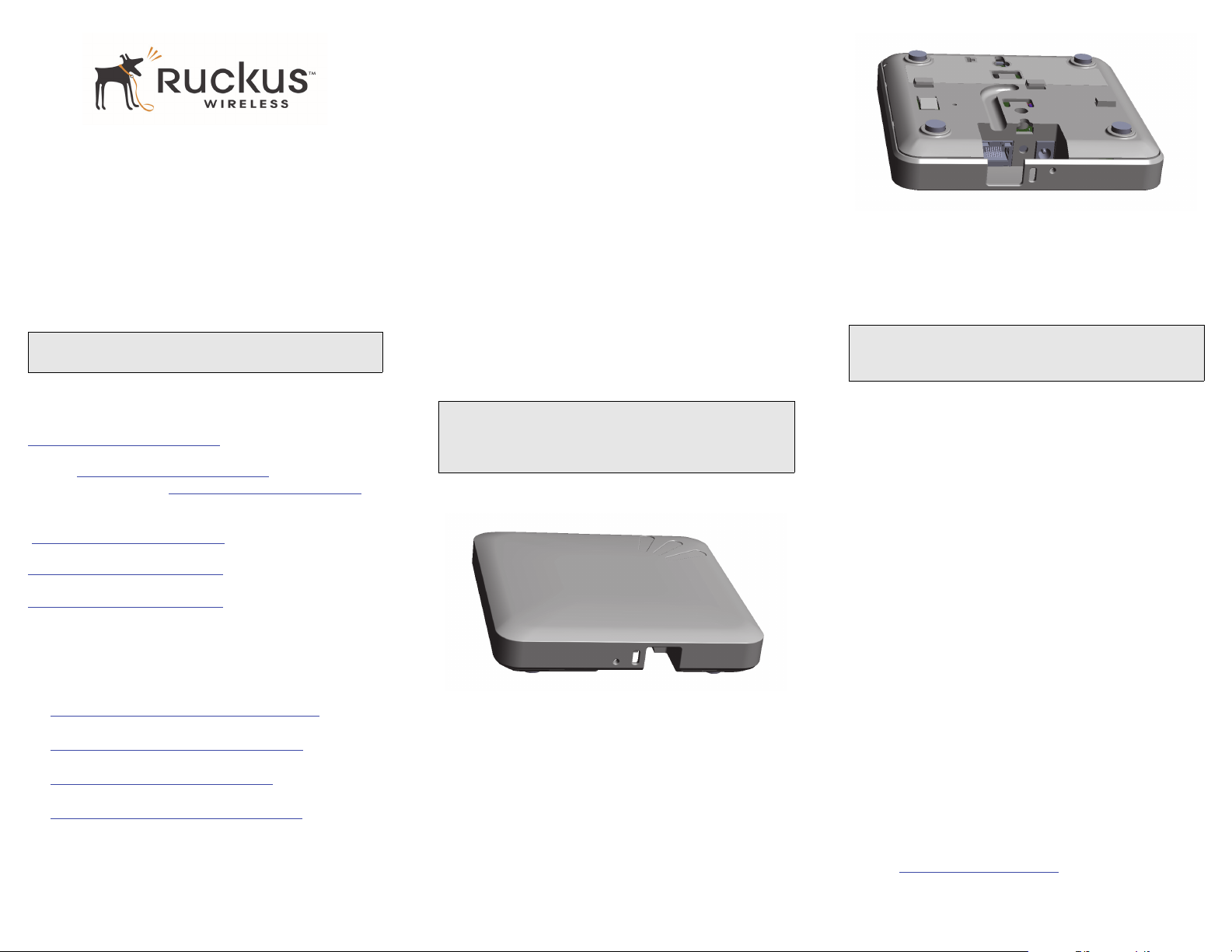
Copyright © 2013 Ruckus Wireless, Inc.
Published June 2013, Part Number 800-70507-001 Rev B
ZoneFlex R300 802.11n
Multimedia Wi-Fi Access Point
Quick Setup Guide
This Quick Setup Guide provides step-by-step instructions
on how to set up your Ruckus Wireless ZoneFlex Access
Point. After completing the steps described in this Guide,
you will be able to place the Access Point (AP) at your site
and provide wireless network access to users.
THIS GUIDE IN OTHER LANGUAGES
请从以下网站获得该指南的简体中文版
https://support.ruckuswireless.com
.
Vous trouverez la version française de ce guide à l'adresse
suivante https://support.ruckuswireless.com
.
こ の ガ イ ド の⽇本語版 は https://support.ruckuswireless.com
でご覧く ださい。
이 가이드의 한국어 버전은 웹 사이트
(https://support.ruckuswireless.com
) 에서 확인하시기 바랍니다 .
Veja a versão em português (Brasil) deste guia em
https://support.ruckuswireless.com.
Puede ver la versión en español (América Latina) de esta guía en
https://support.ruckuswireless.com.
BEFORE YOU BEGIN
Before deploying Ruckus Wireless products, please check for
the latest software and the release documentation.
• User Guides and Release Notes are available at
http://support.ruckuswireless.com/documents.
• Software Upgrades are available at
http://support.ruckuswireless.com/software.
• Open Source information is available at
http://opensource.ruckuswireless.com.
• Software License and Limited Warranty available at
http://support.ruckuswireless.com/warranty.
PACKAGE CONTENTS
• ZoneFlex R300 Access Point
• Mounting screws and anchors (2)
• Security screw
• Pin removal tool
• Regulatory flyer
•This Quick Setup Guide
SETUP REQUIREMENTS
• A computer running Windows 7 (procedures for other OS’s
are similar)
• One or more of the following:
• A modem (DSL or cable), broadband router, or other
device provided by your Internet Service Provider
that brings Internet access to your site.
• A network switch or a DSL/Internet gateway device.
• Two Cat 5e Ethernet cables
• An AC power adapter (sold separately), or
• An 802.3af or 802.3at -compliant Power over Ethernet (PoE)
switch or PoE injector
STEP 1: CONNECT THE AP TO YOUR COMPUTER
1 After removing your Ruckus Wireless AP from its package,
place it next to your computer.
2 Using an Ethernet cable, connect your computer’s network
port to the 10/100/1000 port on the AP.
3 Using the AC adapter (sold separately), connect the AP to a
convenient (and protected) power source.
• Alternatively, connect the 10/100/1000 port to a PoE
injector or PoE switch for both power and network
connectivity.
4
Verify that the Power LED on the external enclosure is a
steady green.
STEP 2: PREPARE YOUR COMPUTER FOR AP
S
ETUP
1 On your Windows 7 computer, configure your network
adapter from the Local Area Connection settings as follows:
• Start > Control Panel > Network and Sharing
Center > Change Adapter Settings
2 Edit the TCP/IPv4 address settings as follows:
• Local Area Connection > Properties > Internet
Protocol Version 4 (TCP/IPv4) > Properties
The TCP/IPv4 Properties dialog box appears.
3
Select Use the following IP address (if it is not already
selected) and then make the following entries:
• IP address: 192.168.0.22 (or any address in the
192.168.0.x network)
•
Subnet mask: 255.255.255.0
•
Default gateway: 192.168.0.1
Leave the
DNS server fields empty.
4
Click OK to save your changes.
Your changes are put into effect immediately.
STEP 3: LOG INTO THE AP
As specified earlier, the AP should be directly connected to
your computer (through the Ethernet port) and powered on,
ready for setup.
1
On your computer, open a Web browser window.
2 In the browser, type this URL to connect to the AP:
https://192.168.0.1
NOTE: The ZoneFlex R300 requires a minimum of Zone-
Flex firmware version 9.7 and above to operate.
IMPORTANT!
If the AP is deployed with a ZoneDirector, follow the
ZoneDirector Quick Setup Guide, and connect the AP to your
local network.
NOTE:
The following procedures assume Windows 7 as the operating
system. Procedures for other OS’s are similar.
Copyright © 2013 Ruckus Wireless, Inc.
Published June 2013, Part Number 800-70507-001 Rev B
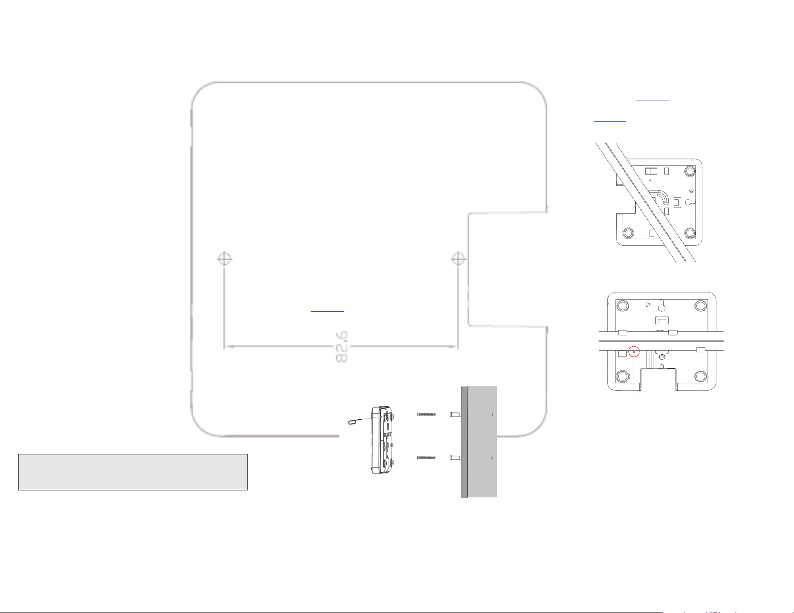
M
OU
NTING TEMPLATE
mm
3 Press <Enter> to initiate the connection. When a security
alert dialog box appears, click
OK/Yes to proceed.
4 When the Ruckus Wireless Admin login page appears, enter
the following:
• Username: super
•
Password: sp-admin
5
Click Login.
STEP 4: CUSTOMIZE THE WIRELESS SETTINGS
1 On the Web interface menu, click Configuration > Wire-
less [2.4G/5G]. The Configure :: Wireless :: Common
options appear.
2 Verify that the following options are active:
• Channel: SmartSelect
•
Country Code: If you are not located in the United
States, select your current country.
3
Click Update Settings if you made any changes.
4 Click any of the eight “Wireless #” tabs at the top of the
page.
5 In Wireless Availability, click Enabled.
6 Delete the text in the SSID field, and then type a name for
your network that will help your users identify the AP in their
wireless network connection application.
7 Click Update Settings to save your changes.
8 Repeat Steps 4-7 for each Wireless # interface that you want
to enable.
9 Click Logout to exit the Web interface.
10 Disconnect the AP from the computer and from the current
power source, and then restore your computer to its original
network connection configuration.
STEP 5: PLACE THE AP IN YOUR SITE
1 Move the AP to its permanent location (accessible to both
AC power and network connection).
2 Use an Ethernet cable to connect the 10/100/1000 port of
the AP to your network.
3 Connect the AC power adapter (or PoE power supply) to the
AP, then to a convenient power source.
4 Verify that the 10/100/1000 port LED is lit.
STEP 6: VERIFY THE INSTALLATION
1 Using any wireless-enabled computer or mobile device,
search for and select the wireless network you previously
configured.
2 If you can connect, open a browser and link to any public
Web site.
Congratulations! Your wireless network is active and ready
for use. If you need to configure advanced wireless settings,
such as enabling security, see the ZoneFlex AP User Guide.
(OPTIONAL) MOUNTING INSTRUCTIONS
The ZoneFlex R300 can be mounted to a wall, ceiling or to a
T-bar using the supplied mounting screws or the T-bar clips
built into the bottom of the AP enclosure.
Mounting to a Flat Surface
1 Use this Quick Start Guide template to mark the locations
for screw holes on the mounting surface. Use a 5mm drill bit
to drill approximately 25mm into the mounting surface.
2 Insert the anchors and mounting screws into the mounting
surface, leaving approximately 1/4” (6 mm) of the screw
heads protruding for the AP enclosure.
The screws should be approximately 3.25” (82.6mm) apart
per the template.
3 Insert the pin removal tool into the hole on the side of the
AP (
Figure 1.), to release the locking mechanism.
Figure 1. Insert the pin removal tool into the pinhole
4 Place the AP onto the mounting screws so that the screw
heads enter the mounting holes on the AP enclosure, and
push the AP (to the left or down depending on orientation)
to lock in place.
5 Remove the pin removal tool to release the lock mechanism
and secure the AP.
6 To unmount, insert the pin removal tool into the hole on the
side of the AP to unlock, then push the AP (to the right or up,
depending on orientation) to release the AP enclosure from
the mounting screws.
Mounting to a T-Bar
1 Orient the AP so that the T-bar is positioned between the T-
bar clips as shown in
Figure 2., then rotate the AP until the
third T-bar clip catches the T-bar and the latch locks the T-bar
in place (
Figure 3.).
Figure 2.
Figure 3.
2 For added physical security, use a Torx screwdriver to insert
the security screw into the hole shown in Figure 3.
3 To remove the unit, first remove the security screw, then
depress the latch while rotating the AP so that the T-bar clips
disengage the T-bar.
FOR MORE INFORMATION
For information on how to configure the AP from the Web
interface, refer to the Ruckus Wireless ZoneFlex Access Point
User Guide or the Online Help, available from within the
Web interface.
NOTE: If you will be using PoE, you will need a Cat 5e (or
better) Ethernet cable to connect the AP to the PoE injec-
tor or switch.
Hold pin removal tool
in while mounting
Security screw hole
Loading...