


 Loading...
R510 Access Point
Quick Setup Guide
This Quick Setup Guide provides step-by-step instructions on how to set up your Ruckus Wireless R510 Dual Band 802.11ac Multimedia Wi-Fi Access Point. After completing the steps described in this Guide, you will be able to place the Access Point (AP) at your site and provide wireless network access to users.
Note: The R510 requires a minimum of ZoneFlex (ZF) firmware version 9.12.2 or later, or SmartZone firmware version 3.2 or later.
THIS GUIDE IN OTHER LANGUAGES
• https://support.ruckuswireless.com.
•Vous trouverez la version française de ce guide à l'adresse suivante https://support.ruckuswireless.com.
•https://
support.ruckuswireless.com
(https://support.ruckuswireless.com).
•Veja a versão em português (Brasil) deste guia em https://support.ruckuswireless.com.
•Puede ver la versión en español (América Latina) de esta guía en https://support.ruckuswireless.com.
BEFORE YOU BEGIN
Before deploying Ruckus Wireless products, please check for the latest software and the release documentation.
•User Guides and Release Notes are available at http://support.ruckuswireless.com/documents.
•Software Upgrades are available at http://support.ruckuswireless.com/software.
•Open Source information is available at http://opensource.ruckuswireless.com.
•Software License and Limited Warranty are available at http://support.ruckuswireless.com/warranty.
Copyright © 2015 Ruckus Wireless, Inc.
Published November 2015, Part Number 800-70940-001 Rev A
PACKAGE CONTENTS
•R510 Access Point
•One wall-mount anchor kit, including two 1" No. 8 steel panhead Phillips sheet metal screws, one 5mm M2.5 x 1.06 Torx security screw, and wall-mount anchors
•One external T-bar bracket (two unassembled parts)
•One unit removal pin
•Regulatory flyer
•Product warranty statement
•Declaration of Conformity, if required
•This Quick Setup Guide
STEP 1: COLLECT TOOLS AND SETUP REQUIRE-
MENTS
•A computer running Windows 7 (procedures for other OS’s are similar)
•Two Cat 5e Ethernet cables
•No. 2 Phillips screwdriver and T8 Torx driver for wall mounting anchor kit
•An AC power adapter (sold separately), or
•an 802.3af or 802.3at -compliant Power over Ethernet (PoE) switch or PoE injector
•When mounting the R510 to a truss or pole, two customersupplied cable ties
IMPORTANT! If the AP is deployed with a ZoneDirector, then refer to the ZoneDirector Quick Setup Guide and connect the AP to your local network.
STEP 2: CONNECT THE AP TO YOUR COMPUTER
Figure 1: Top view
1After removing your Ruckus Wireless AP from its package, place it next to your computer.
2Using an Ethernet cable, connect your computer’s network port to one of the two ports on the AP.
3Using an AC adapter (sold separately), connect the AP 12VDC port to a protected power source.
Alternatively, connect the PoE port to a PoE injector or switch for both power and network connections.
4Verify that the Power LED on the external enclosure is a steady green.
Figure 2: Bottom view
STEP 3: PREPARE YOUR COMPUTER FOR AP
SETUP
Note: The following procedures assume Windows 7 as the operating system. Procedures for other OS’s are similar.
1On your Windows 7 computer, configure your network adapter from the Local Area Connection settings as follows:
•Start > Control Panel > Network and Sharing Center > Change Adapter Settings
2Edit the TCP/IPv4 address settings as follows:
•Local Area Connection > Properties > Internet
Protocol Version 4 (TCP/IPv4) > Properties
The TCP/IPv4 Properties dialog box appears.
Important! Write down all of the currently active settings so you can restore your computer to its current configuration later (when this process is complete).
3Select Use the following IP address (if it is not already selected) and then make the following entries:
•IP address: 192.168.0.22 (or any address in the 192.168.0.x network)
•Subnet mask: 255.255.255.0
•Default gateway: 192.168.0.1
Leave the DNS server fields empty.
4 Click OK to save your changes.
Your changes are put into effect immediately.
Page 1 of 4
STEP 4: LOG INTO THE AP
As specified earlier, the AP should be directly connected to your computer (through one of the Ethernet ports) and powered on, ready for setup.
1On your computer, open a Web browser window.
2In the browser, type this URL to connect to the AP: https://192.168.0.1
3Press <Enter> to initiate the connection. When a security alert dialog box appears, click OK/Yes to proceed.
4When the Ruckus Wireless Admin login page appears, enter the following:
•Username: super
•Password: sp-admin
5Click Login.
STEP 5: CUSTOMIZE THE WIRELESS SETTINGS
Default AP Settings (For Your Reference)
Network Names (SSIDs) |
Wireless1—Wireless8 |
|
(2.4GHz radio) |
|
Wireless9—Wireless16(5GHz |
|
radio) |
Security (Encryption method) Disabled for each wireless interface
Default Management IP |
192.168.0.1 |
Address |
|
1On the Web interface menu, click Configuration >
Radio 2.4G or Configuration > Radio 5G. The Configure :: Wireless :: Common options appear.
2Verify that the following options are active:
•Channel: SmartSelect
•Country Code: If you are not located in the United States, select your current country.
3Click Update Settings if you made any changes.
4Click any of the “Wireless #” tabs at the top of the page.
5In Wireless Availability, click Enabled.
6Delete the text in the SSID field, then type a name for your network that will help your users identify the AP in their wireless network connection application.
7Click Update Settings to save your changes.
8Repeat Steps 4-7 for each Wireless # interface that you want to enable.
9 Click Logout to exit the Web interface.
Optional: If You Want To Switch from DHCP (Default):
If you anticipate logging into the AP regularly to perform monitoring or maintenance once it is in place, you may want to consider assigning a static IP address to the AP.
In a default AP configuration, the AP uses a DHCPassigned IP address.
A.On the menu, click Configuration > Internet.
B.Click the Static IP option.
C.Fill in the IP Address and Mask fields.
D.Click Update Settings to save your changes.
10When the Ruckus Wireless Admin login page reappears, you can exit your browser.
11Disconnect the AP from the computer and from the current power source, and then restore your computer to its original network connection configuration.
STEP 6: PLACE THE AP IN YOUR SITE
1Move the AP to its permanent location (accessible to both power and network connections). Refer to (Optional) Mounting Instructions for physical installation.
2Use an Ethernet cable to connect the PoE port to the appropriate device:
•The ISP’s or carrier’s network device
•The Ethernet switch that is connected to the ISP’s or carrier’s network device
Note: If you will be using PoE, then you will need a Cat 5e (or better) Ethernet cable to connect the AP to the PoE injector or switch.
3Connect the AP power adapter (or PoE power supply) to the AP, then to a convenient power source.
4Verify that the PoE port LED is lit.
After a short pause to re-establish the Internet connection, you can test the AP.
STEP 7: VERIFY THE INSTALLATION
1Using any wireless-enabled computer or mobile device, search for and select the wireless network you previously configured.
2If you can connect, open a browser and link to any public Web site.
Congratulations! Your wireless network is active and ready for use.
FOR MORE INFORMATION
You can now use the wireless network to log into the AP’s Web interface. For information on how to configure the AP, refer to the Ruckus Wireless ZoneFlex Indoor Access Point User Guide.
(OPTIONAL) MOUNTING INSTRUCTIONS
The R510 can be mounted to a T-bar, wall or ceiling a using the enclosed mounting kits. Refer to the following sections:
•Mounting on a Flat Surface
•Mounting on a Recessed Drop-Ceiling T-Bar
•Mounting on a Flush Drop-Ceiling T-Bar
•Mounting on a Truss or Pole
Mounting on a Flat Surface
1Use the Mounting Template on the last page of this Quick Setup Guide as a template to mark the locations for drill holes on the mounting surface. There are two sets of keyholes available on the AP. One allows the AP to be mounted to a wall or ceiling. The other allows the R510 to be mounted to an accessory bracket (not included).
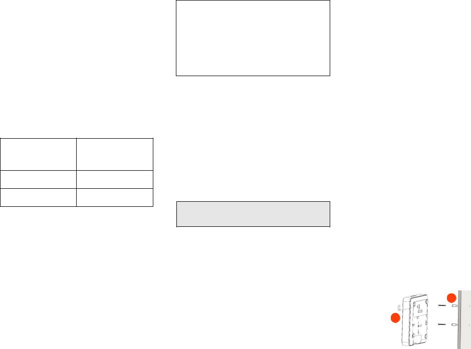
2Use a 5mm drill bit to drill holes approximately 25mm into the mounting surface (A in Figure 3).
3Insert the anchors and mounting screws into the mounting surface, leaving approximately 1/4” (6 mm) of the screw heads protruding for the AP enclosure.
4Insert the unit removal pin into the hole on the side of the AP to release the locking mechanism (B in Figure 3).
5Place the AP onto the mounting screws so that the screw heads enter the mounting holes on the AP enclosure, and push the AP down to lock in place.
6Remove the unit removal pin to release the locking mechanism and secure the AP.
7To remove the AP, insert the unit removal pin into the hole on the side of the AP to unlock, then push the AP up to release the AP enclosure from the mounting screws.
Figure 3. Flat surface mounting
A
B
Copyright © 2015 Ruckus Wireless, Inc. |
Page 2 of 4 |
Published November 2015, Part Number 800-70940-001 Rev A |
|
Loading...