

Page 1

MF 2201 Gateway
MF2201 MetroFlex Wireless Access Gateway User’s Guide
Part number: 8000003
December 2005
Page 2

Copyright © 2005 Ruckus Wireless, Inc. All rights reserved. December 2005.
Trademarks
Ruckus Wireless, BeamFlex™, MediaFlex™, MediaFlex 2900 Multimedia Access Point, MF 2201 MetroFlex Wireless Access
Gateway, MF2900 AP, and MF 2201 Gateway are trademarks of Ruckus Wireless Web Interface
All other brand and product names are registered trademarks of their respective holders.
Statement of Conditions
In the interest of improving internal design, operational function, and/or reliability , Ruckus W ireless, Inc. reserves the right to make
changes to the products described in this document without notice.
Ruckus Wireless, Inc. does not assume any liability that may occur due to the use or application of the product(s) or circuit layout(s)
described herein.
Federal Communications Commission (FCC) Compliance Notice: Radio Frequency Notice
The device has met the FCC 15.247 requirement. In order to comply with the FCC RF exposure requirement, the user must keep
20cm away from the antenna.
This device has been tested and found to comply with the limits for a Class B digital device, pursuant to part 15 of the FCC Rules.
These limits are designed to provide reasonable protection against harmful interference in a residential installation. This device
generates, uses, and can radiate radio frequency energy and, if not installed and used in accordance with the instructi ons, may cause
harmful interference to radio communications. However, there is no guarantee that interference will not occur in a particular
installation. If this device does cause harmful interference to radio or television reception, which can be determined by turning the
equipment off and on, the user is encouraged to try to correct the interference by one or more of the following measures:
• Reorient or relocate the receiving antenna.
• Increase the separation between the equipment and receiver.
• Connect the equipment into an outlet on a circuit different from that to which the receiver is connected.
• Consult the dealer or an experienced radio/TV technician for help.
Changes or modifications not expressly approved by the party responsible for compliance could void the user's authority to operate
the equipment.
Information to the user
The user’s manual or instruction manual for an intentional or unintentional radiator shall caution the user that changes or
modifications not expressly approved by the party responsib le for compliance could void the user’s authority to operate the
equipment. In cases where the manual is provided only in a form other than paper, such as on a computer disk or over the Internet,
the information required by this section may be included in the manual in that alternative form, provided the user can reasonably be
expected to have the capability to access information in that form.
EN 55 022 Declaration of Conformance
This is to certify that the MF 2201 MetroFlex Wireless Access Gateway is shielded against the generation of radio interference in
accordance with the application of Council Directive 89/336/EEC, Article 4a. Conformity is declared by the application of EN 55
022 Class B (CISPR 22).
2 MF2201 MetroFlex Wireless Access Gateway User’s Guide 8000003, December 2005
Page 3

Contents
Preface . . . . . . . . . . . . . . . . . . . . . . . . . . . . . . . . . . . . . . . . . . . . . . . . . . . . . . . . . . . . . 5
Who Should Use this Guide . . . . . . . . . . . . . . . . . . . . . . . . . . . . . . . . . . . . . . . . . . . . . . . . . . . . . . . . 5
What You’ll Find in this Guide . . . . . . . . . . . . . . . . . . . . . . . . . . . . . . . . . . . . . . . . . . . . . . . . . . . . . 5
Typographic conventions . . . . . . . . . . . . . . . . . . . . . . . . . . . . . . . . . . . . . . . . . . . . . . . . . . . . . . . . . . 5
System Requirements . . . . . . . . . . . . . . . . . . . . . . . . . . . . . . . . . . . . . . . . . . . . . . . . . . . . . . . . . . . . . 6
Support and Warranty Information. . . . . . . . . . . . . . . . . . . . . . . . . . . . . . . . . . . . . . . . . . . . . . . . . . . 6
Chapter 1: Introduction. . . . . . . . . . . . . . . . . . . . . . . . . . . . . . . . . . . . . . . . . . . . . 7
MetroFlex™ . . . . . . . . . . . . . . . . . . . . . . . . . . . . . . . . . . . . . . . . . . . . . . . . . . . . . . . . . . . . . . . . . . . . 8
BeamFlex™ . . . . . . . . . . . . . . . . . . . . . . . . . . . . . . . . . . . . . . . . . . . . . . . . . . . . . . . . . . . . . . . . . . . . 8
Key Features. . . . . . . . . . . . . . . . . . . . . . . . . . . . . . . . . . . . . . . . . . . . . . . . . . . . . . . . . . . . . . . . . . . . 8
Chapter 2: Installation and Setup. . . . . . . . . . . . . . . . . . . . . . . . . . . . . . . . . . . . . 11
Packing List . . . . . . . . . . . . . . . . . . . . . . . . . . . . . . . . . . . . . . . . . . . . . . . . . . . . . . . . . . . . . . . . . . . . 12
MF 2201 MetroFlex Wireless Access Gateway. . . . . . . . . . . . . . . . . . . . . . . . . . . . . . . . . . . . . . . . . 12
Front View . . . . . . . . . . . . . . . . . . . . . . . . . . . . . . . . . . . . . . . . . . . . . . . . . . . . . . . . . . . . . . . . . . 12
LED Status Lights. . . . . . . . . . . . . . . . . . . . . . . . . . . . . . . . . . . . . . . . . . . . . . . . . . . . . . . . . . . . . . . . 13
Rear View. . . . . . . . . . . . . . . . . . . . . . . . . . . . . . . . . . . . . . . . . . . . . . . . . . . . . . . . . . . . . . . . . . . 14
Placement Guidelines . . . . . . . . . . . . . . . . . . . . . . . . . . . . . . . . . . . . . . . . . . . . . . . . . . . . . . . . . . . . . 15
Establishing a good general location . . . . . . . . . . . . . . . . . . . . . . . . . . . . . . . . . . . . . . . . . . . . . .15
Using the Air Quality Indicator to fine-tune the placement. . . . . . . . . . . . . . . . . . . . . . . . . . . . . 15
Connecting to the MF 2201 Gateway. . . . . . . . . . . . . . . . . . . . . . . . . . . . . . . . . . . . . . . . . . . . . . . . . 15
Manually Configuring an IP Address on Your PC . . . . . . . . . . . . . . . . . . . . . . . . . . . . . . . . . . . 15
Connecting a PC to the MF 2201 Gateway . . . . . . . . . . . . . . . . . . . . . . . . . . . . . . . . . . . . . . . . . 16
Accessing the Web Interface . . . . . . . . . . . . . . . . . . . . . . . . . . . . . . . . . . . . . . . . . . . . . . . . . . . . . . . 17
Chapter 3: Using the Ruckus Wireless Web Interface . . . . . . . . . . . . . . . . . . . . 19
Wireless Settings Worksheet . . . . . . . . . . . . . . . . . . . . . . . . . . . . . . . . . . . . . . . . . . . . . . . . . . . . . . . 20
MF 2201 Gateway Settings Worksheet . . . . . . . . . . . . . . . . . . . . . . . . . . . . . . . . . . . . . . . . . . . . . . .21
Ruckus Wireless Web Interface Menus . . . . . . . . . . . . . . . . . . . . . . . . . . . . . . . . . . . . . . . . . . . . . . . 22
Common Buttons . . . . . . . . . . . . . . . . . . . . . . . . . . . . . . . . . . . . . . . . . . . . . . . . . . . . . . . . . . . . . 22
Air Quality Indicator. . . . . . . . . . . . . . . . . . . . . . . . . . . . . . . . . . . . . . . . . . . . . . . . . . . . . . . . . . . . . . 22
Configuring the MF 2201 Gateway . . . . . . . . . . . . . . . . . . . . . . . . . . . . . . . . . . . . . . . . . . . . . . . . . . 24
System Configuration. . . . . . . . . . . . . . . . . . . . . . . . . . . . . . . . . . . . . . . . . . . . . . . . . . . . . . . . . . 24
Customizing the System Configuration. . . . . . . . . . . . . . . . . . . . . . . . . . . . . . . . . . . . . . . . . . . . 25
Configuring the Wireless Interface . . . . . . . . . . . . . . . . . . . . . . . . . . . . . . . . . . . . . . . . . . . . . . .26
Advanced Wireless Configuration . . . . . . . . . . . . . . . . . . . . . . . . . . . . . . . . . . . . . . . . . . . . . . . 28
Configuring WEP Security . . . . . . . . . . . . . . . . . . . . . . . . . . . . . . . . . . . . . . . . . . . . . . . . . . . . . 30
Configuring WPA PSK . . . . . . . . . . . . . . . . . . . . . . . . . . . . . . . . . . . . . . . . . . . . . . . . . . . . . . . . 33
Viewing System Information . . . . . . . . . . . . . . . . . . . . . . . . . . . . . . . . . . . . . . . . . . . . . . . . . . . . . . . 34
System Information . . . . . . . . . . . . . . . . . . . . . . . . . . . . . . . . . . . . . . . . . . . . . . . . . . . . . . . . . . . 34
Viewing Wireless Information . . . . . . . . . . . . . . . . . . . . . . . . . . . . . . . . . . . . . . . . . . . . . . . . . . . . . . 35
8000003, December 2005 MF2201 MetroFlex Wireless Access Gateway User’s Guide 3
Page 4

Viewing Statistics . . . . . . . . . . . . . . . . . . . . . . . . . . . . . . . . . . . . . . . . . . . . . . . . . . . . . . . . . . . . . . . 37
Viewing LAN Interface Statistics . . . . . . . . . . . . . . . . . . . . . . . . . . . . . . . . . . . . . . . . . . . . . . . .37
Viewing Wireless Statistics . . . . . . . . . . . . . . . . . . . . . . . . . . . . . . . . . . . . . . . . . . . . . . . . . . . . . 38
Viewing Remote AP Statistics. . . . . . . . . . . . . . . . . . . . . . . . . . . . . . . . . . . . . . . . . . . . . . . . . . .41
Updating the Firmware. . . . . . . . . . . . . . . . . . . . . . . . . . . . . . . . . . . . . . . . . . . . . . . . . . . . . . . . . . . . 43
Performing a Web Download. . . . . . . . . . . . . . . . . . . . . . . . . . . . . . . . . . . . . . . . . . . . . . . . . . . .43
TFTP or FTP Download. . . . . . . . . . . . . . . . . . . . . . . . . . . . . . . . . . . . . . . . . . . . . . . . . . . . . . . . 45
Rebooting the System. . . . . . . . . . . . . . . . . . . . . . . . . . . . . . . . . . . . . . . . . . . . . . . . . . . . . . . . . . . . . 46
Taking a System Support Snapshot . . . . . . . . . . . . . . . . . . . . . . . . . . . . . . . . . . . . . . . . . . . . . . . . . . 48
Appendix A: Technical Specifications . . . . . . . . . . . . . . . . . . . . . . . . . . . . . . . . . . . 51
Physical Characteristics . . . . . . . . . . . . . . . . . . . . . . . . . . . . . . . . . . . . . . . . . . . . . . . . . . . . . . . . . . . 51
Performance and Supported Configurations. . . . . . . . . . . . . . . . . . . . . . . . . . . . . . . . . . . . . . . . . . . . 51
Traffic Management and QoS . . . . . . . . . . . . . . . . . . . . . . . . . . . . . . . . . . . . . . . . . . . . . . . . . . . . . . 52
Management . . . . . . . . . . . . . . . . . . . . . . . . . . . . . . . . . . . . . . . . . . . . . . . . . . . . . . . . . . . . . . . . . . . . 52
4 MF2201 MetroFlex Wireless Access Gateway User’s Guide 8000003, December 2005
Page 5
Who Should Use this Guide
Preface
This MF2201 MetroFlex Wireless Access Gateway User’s Guide will help you understand the
MF 2201 MetroFlex Wireless Access Gateway, how to install it, and configure it using the
Ruckus Wireless Web Interface.
Who Should Use this Guide
This User’s Guide assumes that the reader has basic to intermediate computer and Internet skills. All the
basic computer networking, Internet, and other information required to configure this device is provided
herein.
What You’ll Find in this Guide
The following topics are covered:
• Chapter 1: “Introduction”
• Chapter 2: “Installation and Setup”
• Chapter 3: “Using the Ruckus Wireless Web Interface”
• Appendix A: “Technical Specifications”
Typographic conventions
This User’s Guide uses the following typographic conventions:
T able 1—Typographic conventions
Typeface or
Symbol
italics Emphasis, book titles, CD names,
bold System menu names, user input Open the Control Panel.
fixed
Meaning Example
Read your User’s Guide thoroughly.
special terms.
Also used to denote optional input if
surrounded by <brackets>
Screen text, URLs, IP addresses Browse to the following IP address:
Enter an address in the range
192.168.0.<2-253>
http://192.168.0.254
8000003, December 2005 MF2201 MetroFlex Wireless Access Gateway User’s Guide 5
Page 6

System Requirements
System Requirements
The MF 2201 MetroFlex Wireless Access Gateway is compatible with most contemporary personal
computers and operating systems that are configured for Internet and wireless networking.
The MF 2201 Gateway is accessed and configured via a Web browser interface. Any of the following Web
browsers are supported:
• Microsoft Internet Explorer 5.0 and higher
• Netscape version 6.0 and higher
• Apple Safari 1.0 and higher
• Mozilla Firefox version 1.0 and higher
Support and Warranty Information
See the Warranty and Support card for detailed information about contacting Technical Support, and the
Warranty terms for your MF 2201 MetroFlex Wireless Access Gateway.
6 MF2201 MetroFlex Wireless Access Gateway User’s Guide 8000003, December 2005
Page 7

Chapter 1: Introduction
Congratulations on your purchase of the MF 2201 MetroFlex Wireless Access Gateway The MF 2201 is a
purpose-built home gateway to deliver the best possible connectivity from subscriber homes to MetroMesh
Wi-Fi networks. MetroMesh Wi-Fi networks provide coverage across wide area using a mesh distribution
of access points based on standard WiFi protocols.
The installation uses outdoor high power MetroMesh routers to achieve coverage for outdoor
wireless devices. Typically, the indoor coverage is inadequate to maintain an acceptable level for
users within the home. The MF 2201 is a Customer Premise Equipment to allow the extension of
the Metro Wifi signals to achieve a robust coverage within home. The MF 2201 communicates with
the MetroMesh routers to allow home devices (such as PC or laptops) to access the Internet.
8000003, December 2005 MF2201 MetroFlex Wireless Access Gateway User’s Guide 7
Page 8
MetroFlex™
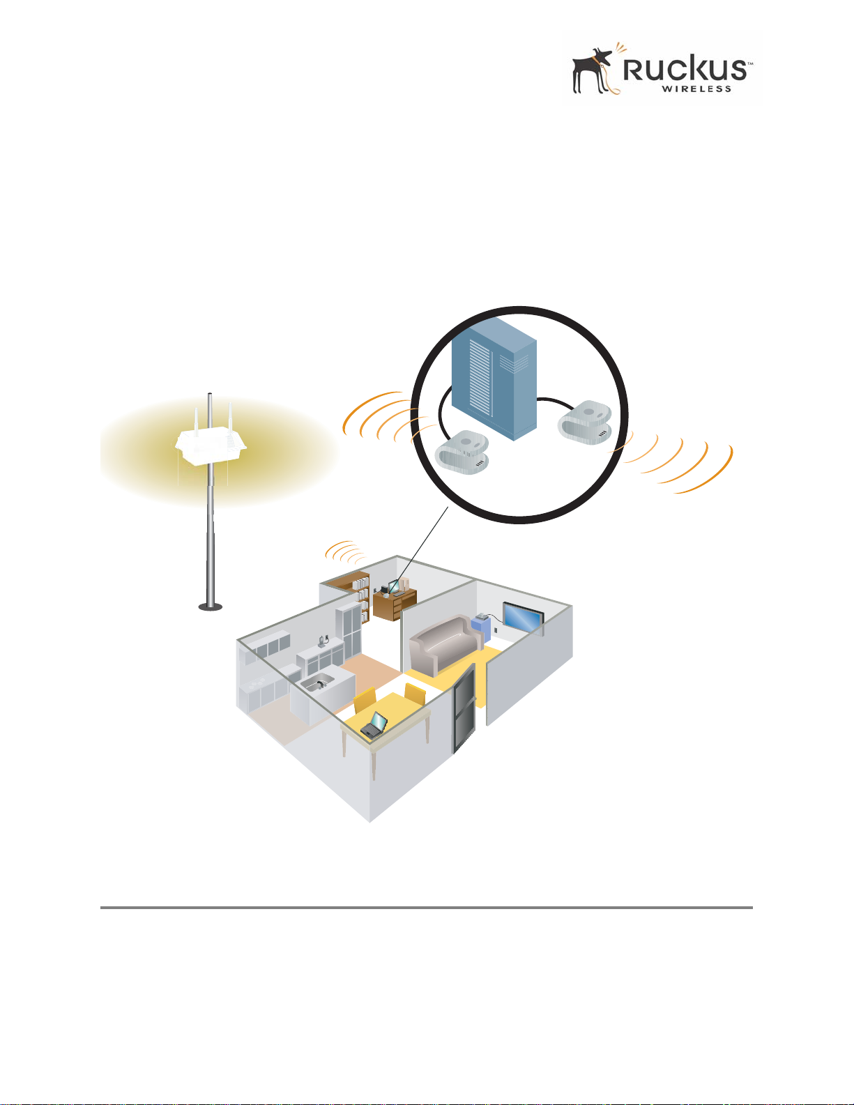
A typical installation consists of a Ruckus Wireless, Inc. MF 2201 MetroFlex Wireless Access Gateway
connected to a set top box. The MF 2201 Gateway receives wireless signals from a MediaFlex 2900
Multimedia Access Point or other remote AP that is connected to a DSL router or cable modem. V ideo, data
and voice traffic are distributed among TV, video appliances, and other wireless-enabled home
entertainment appliances.
Ruckus MF2201 for
predictable broadband
connection to metro
Wi-Fi service
Ruckus
MF2201
In-home
broadband
router
Existing
in-home
Wi-Fi
Existing Wi-Fi AP
provides in-home
IP connectivity
Figure 1—The MF 2201 MetroFlex Wireless Access Gateway in a Typical Home Network
MetroFlex™
MetroFlex™ is Ruckus Wireless, Inc.’s family of purpose-built, multimedia WiFi appliances that enable
reliable wireless metro-area wi-fi network access.
8 MF2201 MetroFlex Wireless Access Gateway User’s Guide 8000003, December 2005
Page 9
BeamFlex™
BeamFlex™
BeamFlex™ is Ruckus Wireless, Inc.’s patent-pending antenna technology that allows wireless signals to
navigate around interference, extend wireless signal range, and increase speeds and capacity for 802.11b/g
wireless networks. The BeamFlex™ antenna system consists of an array of six high-gain antenna elements,
that allow the MF2201 to find quality signal paths in a changing environment, and sustain the baseline
performance required in a metro wi-fi environment.
Key Features
BeamFlex™ Smart MIMO Antenna Maximizes Wireless Range and Performance
• Multi-In, Multi-Out (MIMO) technology supports real time learning of Radio Frequency , station, network
and application conditions.
• On-the-fly adaptation to each receiving device in respo nse to environmental changes such as interference
to maximize signal quality , data rate and minimize packet errors and retransmissions.
• Internal driver software controls an antenna array with 6 high-gain, directional antenna elements and 63
unique antenna combinations.
• Expert system 802.1 1 driver controls data rate and retransmission policies on a per -packet basis.
Media QoS Ensures Highest Video Quality
• Automatic traffic classification and T ype-of-Service (TOS) tagging eliminates complex QoS
configurations.
• Priority queuing for voice, video, best-effort and background traf fic, per W iFi Alliance WiFi Multimedia
(WMM) specifications.
• Strict priority with short (2 frames) hardware queue depth to ensure rapid feedback from the remote AP.
8000003, December 2005 MF2201 MetroFlex Wireless Access Gateway User’s Guide 9
Page 10

Key Features
Multiple Concurrent Video Streams with Simultaneous Data Traffic
• Delivers 15-20 Mbps of bandwidth at 99.9% availability throughout a typical 2500ft2 (300m2) home.
• Supports one MPEG-4/WMV stream, one DVD-quality MPEG-2 streams, or one 10Mbps+ high
definition video stream at 50ft (18m), with simultaneous data traffic.
Simple Configuration and Installation
• Simple W eb-based user interface for easy configuration and customization of features such as SSID, WEP
or WPA key, statistics monitoring and software upgrade.
Standards-based Solution Protects User Investment, Minimizes Replacement Cost
• Compliant with 802.1 1b and 802.1 1g: supports 802.1 1g wireless networking at up to 108 Mbps; and can
interoperate in 802.11g-only or mixed networks.
• Compliant with 802.1x (WEP and WPA with TKIP) and Wi-Fi Alliance WMM specifications.
• Supports W i-Fi Protected Access-Pre-Shared Key (WPA-PSK) data encryption. WPA provides strong
data encryption and authentication based on a pre-shared key .
• Supports 64-bit and 128-bit WEP encryption security. WEP keys can be generated manually or by
passphrase.
• Attaches to television set-top box via Ethernet to optimize the reception of quality internet video over the
WLAN.
• Forward compatible with the emerging 802.1 1n WLAN standard.
10 MF2201 MetroFlex Wireless Access Gateway User’s Guide 8000003, December 2005
Page 11

Chapter 2: Installation and Setup
This chapter describes how to install your MF 2201 MetroFlex Wireless Access Gateway, and how to set
up your PC to connect to the Ruckus Wireless Web Interface.
Topics covered in this chapter include:
Packing List. . . . . . . . . . . . . . . . . . . . . . . . . . . . . . . . . . . . . . . . . . . . . . . . . . . . . . . . . . . . . . . . . . . . . . . . . . . . 12
MF 2201 MetroFlex Wireless Access Gateway . . . . . . . . . . . . . . . . . . . . . . . . . . . . . . . . . . . . . . . . . . . . . . . 12
LED Status Lights. . . . . . . . . . . . . . . . . . . . . . . . . . . . . . . . . . . . . . . . . . . . . . . . . . . . . . . . . . . . . . . . . . . . . . . 13
Placement Guidelines . . . . . . . . . . . . . . . . . . . . . . . . . . . . . . . . . . . . . . . . . . . . . . . . . . . . . . . . . . . . . . . . . . . . 15
Connecting to the MF 2201 Gateway . . . . . . . . . . . . . . . . . . . . . . . . . . . . . . . . . . . . . . . . . . . . . . . . . . . . . . . 15
Accessing the W eb Interface . . . . . . . . . . . . . . . . . . . . . . . . . . . . . . . . . . . . . . . . . . . . . . . . . . . . . . . . . . . . . . 17
8000003, December 2005 MF2201 MetroFlex Wireless Access Gateway User’s Guide 11
Page 12
Packing List
Packing List
1. MF 2201 MetroFlex Wireless Access Gateway
2. AC power adapter (Input DC 5-18V 1-2A)
3. Category 5 (CAT5) Ethernet Cable
4. MF 2201 MetroFlex Wireless Access Gateway Quick Setup Guide
MF 2201 MetroFlex Wireless Access Gateway
Front View
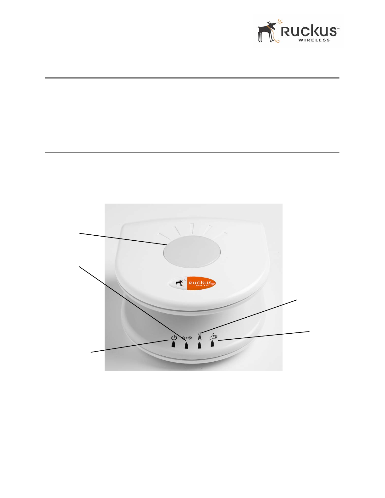
Figure 2— “Front View of the MF 2201 MetroFlex Wireless Access Gateway” shows the front view MF
2201 Gateway, with the LED indicators numbered. The numbers correspond to the labels describing LED
behavior in Table 2— “LED Indicators and Meanings” on page 13.
1
3
2
Figure 2—Front View of the MF 2201 MetroFlex Wireless Access Gateway
4
5
12 MF2201 MetroFlex Wireless Access Gateway User’s Guide 8000003, December 2005
Page 13
LED Status Lights
LED Status Lights
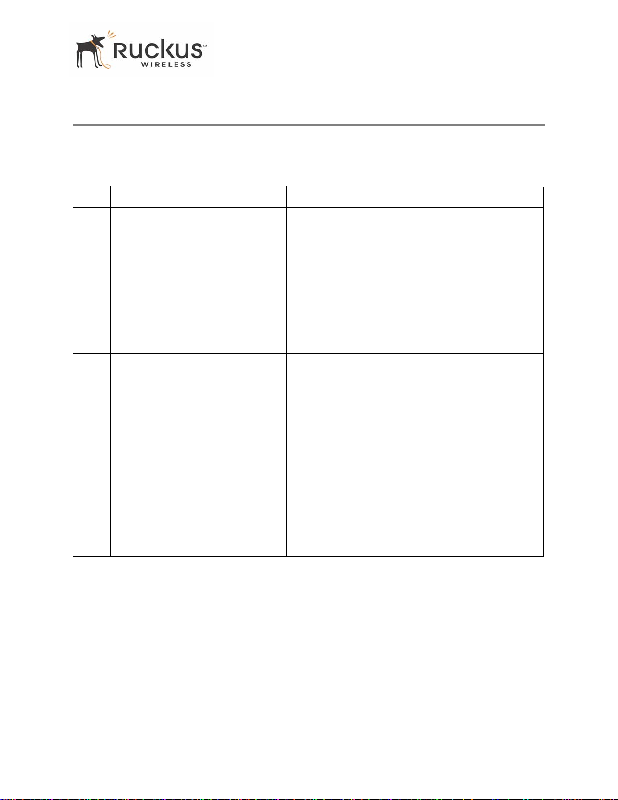
T able 2— “LED Indicators and Meanings” describes the LED lights on the front of the MF 22 01 Gateway.
T able 2—LED Indicators and Meanings
Label LED Activity Description
1 Antenna All LEDs On Green
Solid
Green Flashing
randomly
2 Power Green
Off
3 LAN Green Steady
Off
4 Wireless Green Flashing
Green Steady
5 Air Quality Green Steady
Green Flashing
Green intermittent
Flashing
The MF 2201 Gateway is booting.
The lit LEDs indicate which antennae are active.
Power is supplied to the MF 2201 Gateway.
Power is not supplied to the MF 2201 Gateway.
The MF 2201 Gateway has link.
The MF 2201 Gateway has no link.
The MF 2201 Gateway is transmitting data. The faster the
flashing, the more data is being transmitted or received.
The Wireless port is initialized and enabled.
Good Air Quality: A steady Green LED indicates that the
current environment will support quality video streaming.
Marginally Acceptable Air Quality: a flashing Green
LED (on for 0.25 second, off 0.25 second) indicates that
the current environment does not always meet the video
standard. While video streaming is possible, the quality will
vary .
Bad Air Quality: A briefly flashing Green LED (on for 0.03
second and off for 1 second) indicates that video streaming
is not possible in the current environment. The brief flash
also indicates that the device is still functioning.
8000003, December 2005 MF2201 MetroFlex Wireless Access Gateway User’s Guide 13
Page 14
LED Status Lights
Rear View
6
7
8
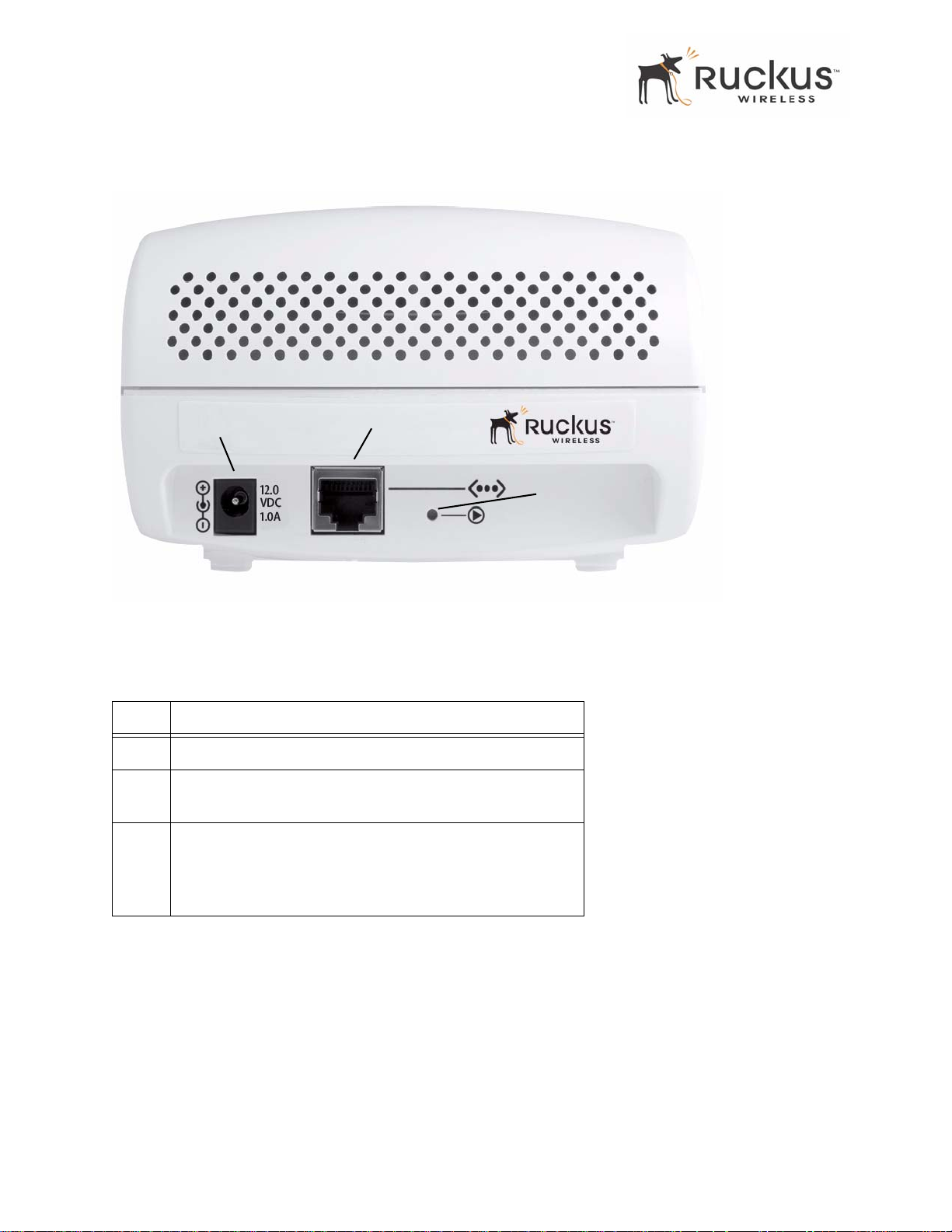
Figure 3—Rear View of the MF 2201 Gateway
Table 3—Rear Port s and Adapters
Label Description
6 AC Power Adapter (Input: DC 5V 2A)
7 10/100 Mbps Auto-sensing, autonegotiating RJ-45 network
port
8
Reset button. Used only if you need to reset the MF 2201
Gateway to its factory default settings. Insert the end of a
paper clip or pin into the hole and hold it in for at least 4
seconds.
14 MF2201 MetroFlex Wireless Access Gateway User’s Guide 8000003, December 2005
Page 15

Placement Guidelines
Placement Guidelines
Y ou or your service provider or installer can determine the best placement for the MF 2201 Gateway by using
the following guidelines.
Establishing a good general location
Your MF 2201 Gateway should be placed:
• On a shelf or other elevated location away from any physical obstructions.
• Away from other sources of electromagnetic interference (for example, microwave ovens, and cordless
phones).
• Away from large metal surfaces, pictures or mirrors.
• Away from large furniture or other physical obstructions.
Using the Air Quality Indicator to fine-tune the placement
Wireless environments are sensitive to the physical arrangement of both electronic devices and furniture in
a room. You or your installer can observe the Air Quality Indicator LED to determine the best location. The
Air Quality indicator LED is described in Table 2— “LED Indicators and Meanings” on page 13.
Your service provider or installer can guide you through a self-help troubleshooting session if video quality
deteriorates after an installation. Or, you may be able to determine a solution to the problem on your own.
If “Bad” or “Maybe Acceptable,” air quality is indicated, you can adjust the location of the MF 2201
Gateway and other devices until a steady green LED indicates “good” air quality.
Connecting to the MF 2201 Gateway
Before using the MF 2201 Gateway, you have to configure it to work within your home network. Your
service provider or installer will likely perform all installation tasks for you, or you may read the following
section to understand how to configure it manually.
The default IP address of the MF 2201 MetroFlex Wireless Access Gateway is
T o gain administrative control of the unit, set your PC or laptop network IP address to an address within the
same network as the MF 2201 Gateway’s default IP address. Then, connect your PC to the MF 2201 Gateway
using the provided Ethernet cable.
You can set your PC’s IP address to an address within the network
192.168.0.100).
192.168.0.<2-253> (Example:
Manually Configuring an IP Address on Your PC
1. Windows 20 00: Start>Settings>Network and Dial-up Connections
Windows XP: S tart>Settings>Contr ol Panel>Network Connections
2. Double-click the icon for the Local Area Connection designated for your home network, then click the
Properties button at the bottom of the screen. (This is not the same icon as your home wireless network.)
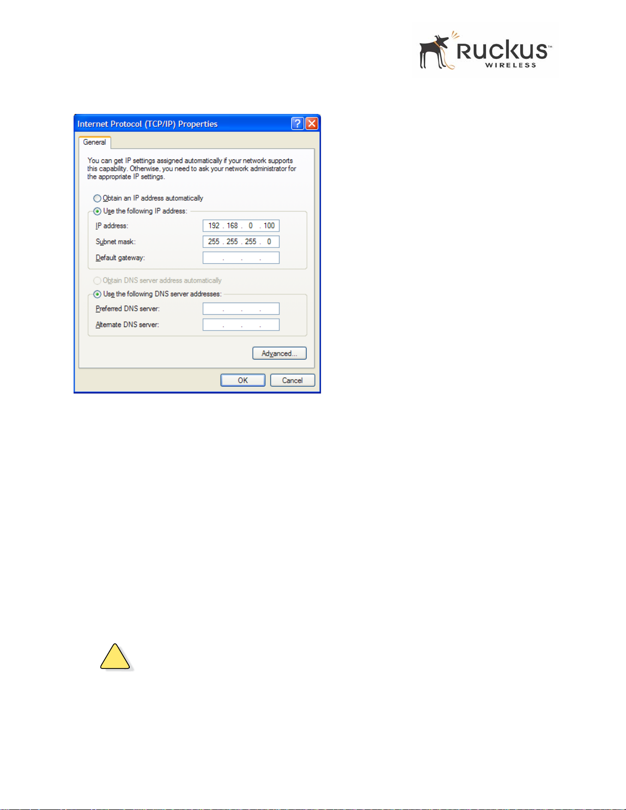
3. In the Local Area Connection Properties window , select Internet Protocol (TCP/IP) and click the Pr operties
button. The Internet Protocol (TCP/IP) Properties window appears ( Figure 4).
192.168.0.254.
8000003, December 2005 MF2201 MetroFlex Wireless Access Gateway User’s Guide 15
Page 16
Connecting to the MF 2201 Gateway
Figure 4—Internet Protocol (TCP/IP)Properties Window
4. Select the Use the following IP address button, and enter an IP address within the netwo rk as noted above.
5. Press Tab and allow the Subnet mask address to auto-fill to 255.255.255.0.
6. Click OK to exit the TCP/IP Properties window .
7. Click OK to exit the Local Area Connection Properties window .
Connecting a PC to the MF 2201 Gateway
The following steps will guide you through connecting to your MF 2201 Gateway.
1. Remove the MF 2201 Gateway from the packaging and place it next to your PC or laptop.
2. Connect the AC Power Supply to the MF 2201 Gateway and connect to a power outlet.
3. Connect your PC or laptop to the Ethernet port on the MF 2201 Gateway using the supplied Ethernet cable.
4. On your PC, open a browser window . Enter the address
5. When the login screen appears, enter the username
http://192.168.0.254.
admin and leave the password field blank. Then click
Logon.
!
CAUTION:—Make sure to write down the new IP address, username, password and SSID. If you change the
MF 2201 Gateway’s default IP address to one outside the current address range of your PC, you will not be
able to connect to the device after reboot until you reset your computer’s IP address to be within the same
network as the MF 2201 Gateway. See Table 5, “Wireless Network Settings Worksheet,” on page 20 and
Table 6, “MF 2201 Gateway Default an d User Set tings Worksheet,” on page 21 for mo re information.
16 MF2201 MetroFlex Wireless Access Gateway User’s Guide 8000003, December 2005
Page 17
Accessing the Web Interface
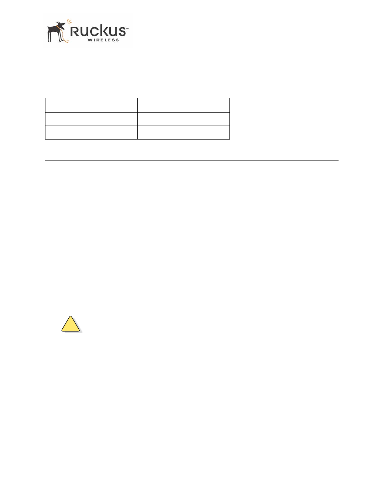
You should now be able to find the default SSID “V54” of your MF 2201 Gateway over your wireless
connection:
T able 4—Default Wireless Settings
Wireless Feature Setting
Network Name (SSID) V54
Security Disabled
Accessing the Web Interface
The MF 2201 Gateway provides a Web-based user interface for configuration and monitoring. For
information about using the Ruckus Wireless Web Interface, refer to Chapter 3:, “Using the Ruckus Wireless
Web Interface .
1. To access the Ruckus Wireless Web Interface, launch a Web browser and enter the MF 2201 Gateway’s IP
address. If this is the first time the access point is being configured, enter the default IP address:
192.168.0.254
2. A logon screen will appear. Use the default logon information:
Username:
admin
Password: <blank>
After logging in, you will see the main information page. On the information page, there are two panes. The
pane on the left shows major information or configuration points. Each major information or configuration
area has a number of sub-menus. Clicking on the relevant menu will bring the relevant page onto the screen.
The system monitors the activities on the Web user interface. If you do not use the Web interface for more
than five minutes, the system will time out, and you will be logged out automatically. You need to re-log in
to access the interface.
!
CAUTION:—Any configuration changes will be lost unless y ou use the Update button. It is recommended
that after each configuration screen you modify, you click the Update button.
8000003, December 2005 MF2201 MetroFlex Wireless Access Gateway User’s Guide 17
Page 18

Accessing the Web Interface
18 MF2201 MetroFlex Wireless Access Gateway User’s Guide 8000003, December 2005
Page 19

Chapter 3: Using the Ruckus Wireless Web Interface
This chapter describes the tasks you need to do to customize the MF 2201 Gateway to run on your wireless
network.
Topics covered in this chapter include:
Wireless Settings Worksheet . . . . . . . . . . . . . . . . . . . . . . . . . . . . . . . . . . . . . . . . . . . . . . . . . . . . . . . . . . . . . . 20
MF 2201 Gateway Settings W orksheet. . . . . . . . . . . . . . . . . . . . . . . . . . . . . . . . . . . . . . . . . . . . . . . . . . . . . . 21
Ruckus Wireless W eb Interface Menus. . . . . . . . . . . . . . . . . . . . . . . . . . . . . . . . . . . . . . . . . . . . . . . . . . . . . . 22
Air Quality Indicator. . . . . . . . . . . . . . . . . . . . . . . . . . . . . . . . . . . . . . . . . . . . . . . . . . . . . . . . . . . . . . . . . . . . . 22
Configuring the MF 2201 Gateway . . . . . . . . . . . . . . . . . . . . . . . . . . . . . . . . . . . . . . . . . . . . . . . . . . . . . . . . 24
V iewing W ireless Information. . . . . . . . . . . . . . . . . . . . . . . . . . . . . . . . . . . . . . . . . . . . . . . . . . . . . . . . . . . . . 35
V iewing Statistics . . . . . . . . . . . . . . . . . . . . . . . . . . . . . . . . . . . . . . . . . . . . . . . . . . . . . . . . . . . . . . . . . . . . . . . 37
Rebooting the System. . . . . . . . . . . . . . . . . . . . . . . . . . . . . . . . . . . . . . . . . . . . . . . . . . . . . . . . . . . . . . . . . . . . 46
T aking a System Support Snapshot . . . . . . . . . . . . . . . . . . . . . . . . . . . . . . . . . . . . . . . . . . . . . . . . . . . . . . . . . 48
8000003, December 2005 MF2201 MetroFlex Wireless Access Gateway User’s Guide 19
Page 20
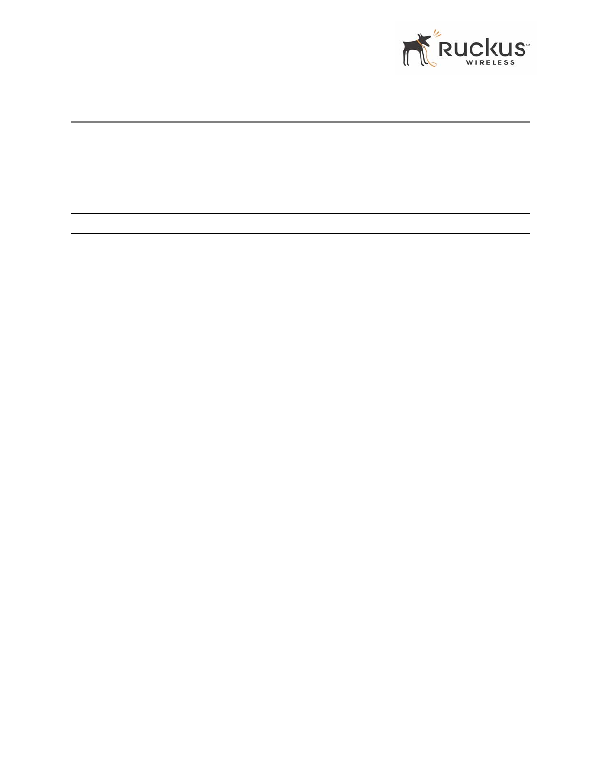
Wireless Settings Worksheet
Wireless Settings Worksheet
Before you modify any wireless settings on the MF 2201 Gateway, print Table 5— “Wireless Network
Settings W orksheet” and record the following information about your wireless network. Y our ISP or network
administrator may provide you with this information. The wireless information recorded in this worksheet
should be used to configure the MF 2201 Gateway’s wireless settings.
T able 5—Wire less Netwo rk Setti ngs W orksh eet
Item Description and Your Network Setting
MF 2201 Gateway
SSID
Security If using WEP, circle the method used: Open SystemShared KeyAuto
The MF 2201 Gateway will not provide Internet access like a home router or
gateway. The SSID identifies the remote AP. Make sure to specify the SSID of the
remote AP. Do not specify a unique SSID for the MF 2201 Gateway. You can use
up to 32 alphanumeric characters. The SSID is case sensitive.
Circle the type of Shared key: 64-bit 128 bit
Passphrase method
• If using 64-bit WEP: use 10 hex digits (any combination of 0-9 or a-f) or 5
ascii characters
• If using 128-bit WEP, use 26 hex digits or 13 ascii characters
The WEP key values are not case-sensitive.
Key 1 ______________________________________________
Key 2 ______________________________________________
Key 3 ______________________________________________
Key 4 ______________________________________________
If using WP A-PSK, write down the passphrase. The WPA-PSK passphrase is
case-sensitive.
WP A Pass phrase : ________________________________
20 MF2201 MetroFlex Wireless Access Gateway User’s Guide 8000003, December 2005
Page 21
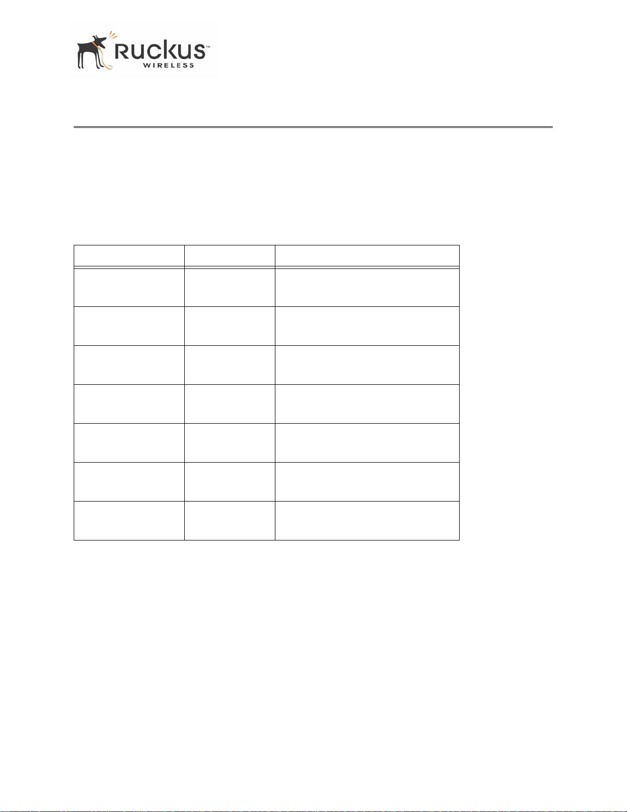
MF 2201 Gateway Settings Worksheet
MF 2201 Gateway Settings Worksheet
Print Table 6, and record your personalized settings for configuring the MF 2201 Gateway. Enter the security
settings you recorded in Table 5, “Wireless Network Settings Worksheet,” on page 20.
Remember—If the MF 2201 Gateway’s device settings do not match the remote AP settings, the MF 2201
Gateway will not be able to find your network.
Store this information in a safe place.
T able 6—MF 2201 Gateway Default and User Settings Worksheet
Item Default Setting Y our Setting
User Name
Password <none>
IP Address
Subnet Mask 255.255.255.0
SSID V54
Wireless Mode 802.11g&b
Security Disabled
admin
192.168.0.1
_______________________________
_______________________________
_______________________________
_______________________________
_______________________________
_______________________________
_______________________________
8000003, December 2005 MF2201 MetroFlex Wireless Access Gateway User’s Guide 21
Page 22
Ruckus Wireless Web Interface Menus
Ruckus Wireless Web Interface Menus
The Ruckus Wireless Web Interface menus are located on the left-hand navigation pane. To select a
particular menu, simply click on the menu link.
Common Buttons
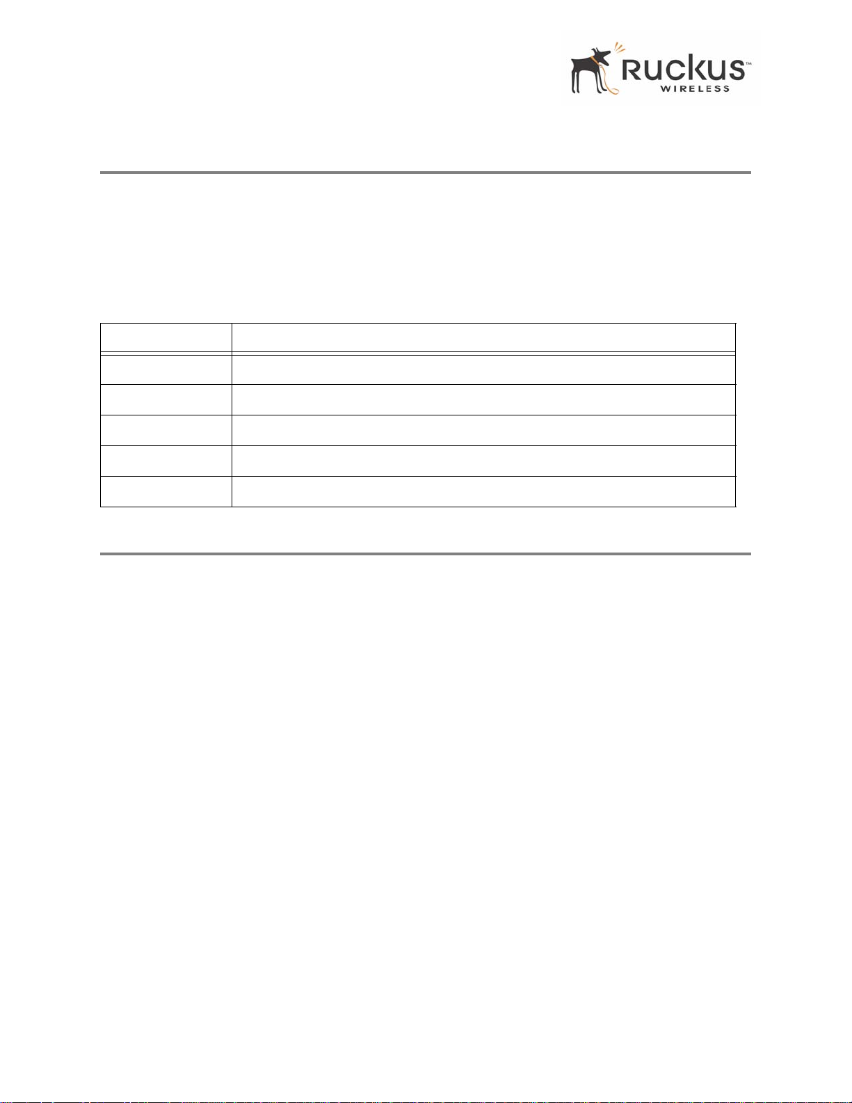
The Ruckus Wireless Web Interface screens contain the following menu buttons (Table 7):
T able 7—Wireless Web Interface Menu Buttons
Button Action
Logout Logs out the current session.
Restore Restores the original configuration.
Update Saves the new configuration.
Next Progresses to the next menu. Only found in the Configuration menus.
Back Reverts to the previous menu. Only found in the Configuration menus.
Air Quality Indicator
The Air Quality indicator icon shows the current state of your Wireless connection. Air Quality is measured
by the Received Signal Strength Indication (RSSI) value, which is a measurement of the wireless signal
strength. A high RSSI value usually means that the wireless connection is stable, and quality video data can
be transferred.
22 MF2201 MetroFlex Wireless Access Gateway User’s Guide 8000003, December 2005
Page 23

Air Quality Indicator
The Air Quality Indicator assesses the environment that surrounds a Ruckus Wireless, Inc. MF 2201
Gateway, and determines the amount of interference in the infrastructure. The Radio Frequency (RF) side
of a wireless device is a combination of a receiver and a transmitter . Both receiver and transmitter provide
feedback as they operate. The Air Quality indicator bases its evaluation on the Received Signal Strength
Indication (RSSI) that is returned as part of the 802.11 transmission acknowledgement. As the adapter
receives an 802.11 packet, it sends the RSSI value to the remote AP.
Thumb Up: Good air quality. The environment supports a quality video viewing
experience.
Thumb sideways: Marginal video signal strength. The current environment may support
video viewing, but it is also possible that the video may be flawed.
Thumb down: Low video signal strength. The current environment do es not support q ual-
ity video viewing.
8000003, December 2005 MF2201 MetroFlex Wireless Access Gateway User’s Guide 23
Page 24
Configuring the MF 2201 Gateway
Configuring the MF 2201 Gateway
This section describes the tasks and screens used to customize the MF 2201 Gateway configuration to run
on your wireless network.
Review the following topics before you change any system configuration settings:
• "Connecting to the MF 2201 Gateway" on page 15
• "Accessing the Web Interface" on page 17.
System Configuration
Table 6, “MF 2201 Gateway Default and User Settings Worksheet,” on page 21 shows the default settings
used to login to the device.
A minimum set of configurations is required to put the MF 2201 Gateway into operational mode. The system
provides the default settings for these configuration items. You should change the default settings where
necessary to match your own wireless network’s configuration, and to protect your privacy.
A system reboot is required for configuration changes to take effect. Follow the following steps to configure
the MF 2201 Gateway:
1. Connect to the MF2201 adapter by following the instructions in "Connecting to the MF 2201 Gateway" on
page 15.
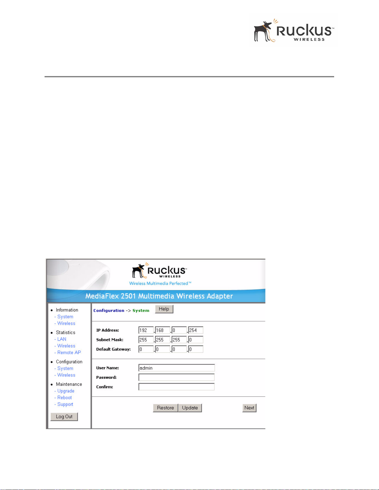
2. Choose Configuration->System.. The window of Figure 5 appears.
Figure 5—System Configuration
24 MF2201 MetroFlex Wireless Access Gateway User’s Guide 8000003, December 2005
Page 25
Configuring the MF 2201 Gateway
3. Enter your configuration changes in the appropriate fields.
4. Click the Next button to go to the next configuration screen.
5. Click the Update button to save your settings.
!
CAUTION:—You must click the Update button to save any configuration changes. The Ruckus
Wireless Web Interface will timeout after 5 minutes of inactivity. If you let the system time out befor e clicking
the Update button, any changes you made will be lost.
6. Click the Restore button to cancel configuration changes.
7. Go to the Boot menu and click the Reboot button to reboot the device for configuration changes to take effect.
!
CAUTION:—If, after having changed any default settings, you have forgotten what the new settings are, you
may not be able to login to the MF 2201 Gateway. T o regain access to the MF 2201 Gateway, you must reset
the device to its factory default settings. Do this by inserting the end of a paper clip into the Reset Button while
the unit is on and keep holding the button down until the green LEDs at the top of the unit briefly go out—
indicating the system is rebooting.
Customizing the System Configuration
It is recommended that you customize the username and password so that you can control who can gain
administrative access to the MF 2201 Gateway. You may also wish to change the default IP address if it
conflicts with another device in your wireless network. Refer to Table 8 for details on each field.
T able 8—System Configuration
Field Description
IP Address
Subnet Mask
Default Gateway The IP address of default gateway. The default is 0.0.0.0.
User Name The user name. The default user name is
Password / Confirm The user password. The default is no password. If you change the password, make
The IP address of the MF 2201 Gateway. This IP address is used only when you need
to access the Ruckus Wireless Web Interface to change configuration or view
information about the MF 2201 Gateway.
The subnet mask of the MF 2201 Gateway. The default is 255.255.255.0. Changing
the Subnet Mask field is not recommended for most installations.
admin. If you change the user name, make
sure to write it down for future reference.
sure to write it down for future reference.
8000003, December 2005 MF2201 MetroFlex Wireless Access Gateway User’s Guide 25
Page 26
Configuring the MF 2201 Gateway
Configuring the Wireless Interface
It is recommended that you consult with your service provider to understand the wireless settings. Before
changing any settings in the Wireless configuration menu, make sure you have recorded and verified the
information in the following worksheets:
• "W ireless Network Setting s Worksheet" on page 20
• "MF 2201 Gateway Default and User Settings Worksheet" on page 21.
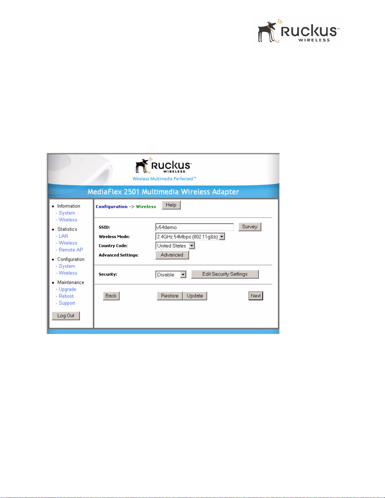
1. After connecting to the MF 2201 Gateway, choose Configuration->Wir eless. The window of Figure 6
appears.
Figure 6—Wireless Interface Configuration
26 MF2201 MetroFlex Wireless Access Gateway User’s Guide 8000003, December 2005
Page 27
Configuring the MF 2201 Gateway
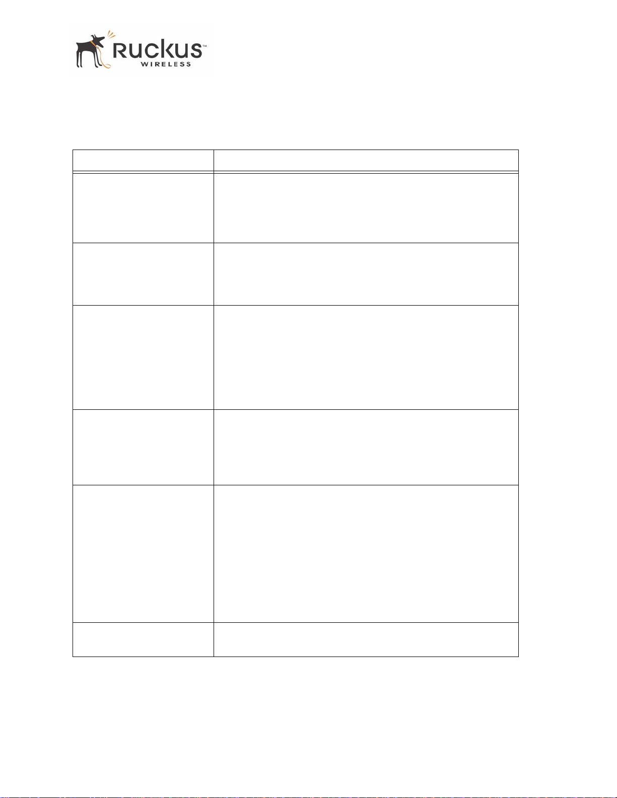
2. Fill in the parameters as described in Table 9.
T able 9—Wireless Interface Configuration
Field Description
SSID The SSID (Service Set IDentifier) is the name of the wireless network.
The default SSID is
change your SSID. If there are other wireless networks in your area,
you should give your wireless network a unique name. The SSID can
consist of up to 32 characters.
Wireless mode The wireless mode options are:
• 2.4GHz 54Mbps (802.11g&b) - allows both 802.11g- and
802.1 1b-compliant devices to join the network. This is the
default setting.
Country Code Sets your country or region code. Selecting the incorrect country or
region may result in violation of applicable law. The selectable
countries or regions are United States, Europe, Hong Kong, and
Japan.
V54, but it is strongly recommended that you
N
OTE – For MF 2201 Gateways shipped in the United States, the
country code cannot be modified. The country code is pre-defined
for United States only.
Advanced Setting This button provides access to the advanced wireless settings.
Advanced wireless settings are for advanced configuration or testing
purposes only .
Changing the advanced settings may negatively affect the operation
of the MF 2201 Gateway and is not recommended.
Security The wireless security options are:
• Disabled: This setting disables all encryption, so traffic is sent
in the clear. This setting is not recommended.
• WEP: This setting enables Wired Equivalent Privacy. WEP
Shared Key authentication and WEP data encryption provides
sufficient security in most cases.
• WPA-PSK: Wi-Fi Protected Access, Pre-Shared Key
(WP A-PSK). Each p acket of information is encrypted with a
different key . Provides very strong security, but may not be
supported on older systems.
Edit Security Setting Click this button to edit the security setting of WEP keys or the
WP A-PSK p assphrase.
8000003, December 2005 MF2201 MetroFlex Wireless Access Gateway User’s Guide 27
Page 28
Configuring the MF 2201 Gateway
Advanced Wireless Configuration
The Advanced Wireless Configuration menu is preconfigured with the optimum settings. Changing the
advanced settings may negatively affect the MF 2201 Gate way’s operation, or completely disable it. For best
results, leave the Advanced settings at their default values and do not change these settings unless directed
by your technical support personnel.
NOTE – If you have modified the advanced settings and wish to revert to the original settings, you can restore the settings by clicking the Restore button, as long as you have not already clicked the Update Button.
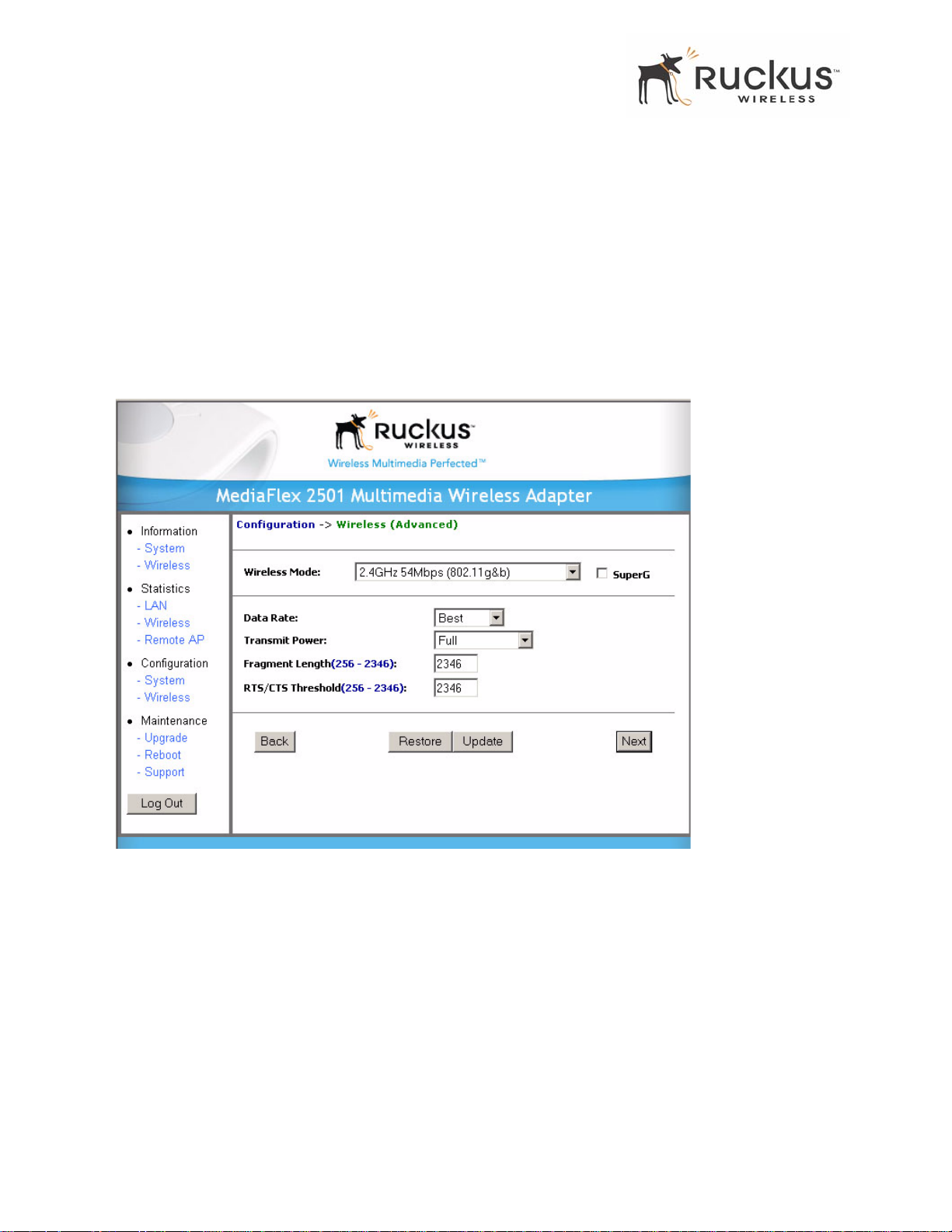
1. After connecting to the MF 2201 Gateway, choose Configuration->Wireless. Then click Advanced. The
window of Figure 7 appears.
Figure 7—Advanced Wireless Configuration
28 MF2201 MetroFlex Wireless Access Gateway User’s Guide 8000003, December 2005
Page 29
Table 10 shows the Advanced Wireless Configuration parameters.
T able 10—Advanced Wireless Configuration Parameters
Field Description
Configuring the MF 2201 Gateway
Wireless Mode
Sets the wireless mode for the MF 2201 Gateway. The wireless mode
determines the wireless speed of devices that are allowed to associate to
the MF 2201 Gateway. Options are:
• 802.1 1g&b: st ations running at either 802.11g (2.4GHz, 54Mbps)
or 802.11 b (2.4GHz 11Mbps) can associate to the MF 2201
Gateway. This is the default setting.
• 2.4GHz 54Mbps (802.1 1g only)
• 2.4GHz Auto 108Mbps (802.1 1g T urbo)
• 2.4GHz Only 108Mbps (802.1 1g Turbo)
!
CAUTION:—Using Turbo and/or super G mode is NOT supported
when running video streams. These modes are intended for
diagnostic and for networks where only non-video traffic is
transmitted.
Super G This check box is used to enable the Super G mode, which engages
advanced mechanisms when extra bandwidth is available and or required.
By default, this option is not checked.
Data Rate Select the desired data rate from the drop-down menu. The default is
Best, which means the system will adjust the data rate automatically.
Transmit Power Select the desired Adapter transmit power from the drop-down menu. In
cases where you might want to limit your signal coverage range, such as
in a small apartment or room, you can select a lower transmit power.
The options are:
•Full
• Half (-3 dB)
• Quarter (-6 dB)
• Eighth (-9 dB)
• Minimum
The default is Full.
8000003, December 2005 MF2201 MetroFlex Wireless Access Gateway User’s Guide 29
Page 30
Configuring the MF 2201 Gateway
T able 10—Advanced Wireless Configuration Parameters (Continued)
Field Description
Fragment length The fragment length. The range is between 256 and 2346 bytes. The
default is 2346.
The MF 2201 Gateway uses fragmentation to divide 802.11 frames into
smaller fragments which are sent separately to the destination. Only
unicast frames can be fragmented. The fragment length can be between
256-2346 bytes. If the data that the MF 2201 Gateway is transmitting is
larger than the threshold, it will trigger the fragmentation function. If the
packet size is equal to or less than the threshold, the access point will not
use fragmentation. In a good wireless environment, the larger the
fragment, the more efficient the network operates. In a noisy environment,
the fragment length should be adjusted to a smaller size to minimize
retransmission and increase the reliability of the transmission.
RTS/CTS Threshold The R TS-CTS threshold range. The range is between 256 and 2346. The
default is 2346.
The RTS-CTS threshold is a value that determines at what frame length
the request-to-send/clear-to-send (RTS-CTS) function is triggered. By
default, this threshold is set at its highest value. A lower threshold value
means that the RTS-CTS function is triggered for smaller frame lengths.
A lower threshold may be necessary in environments with excessive
signal noise or hidden nodes; but this may result in some performance
degradation.
We need to make a glaring warning about not using turbo or super G when using IPTV applications.
Something like: Using Turbo and/or super G mode is NOT supported when running video streams, these
modes are intended for diagnostic and for networks where only non- video traffic is transmitted.
!
CAUTION:—Using Turbo and/or super G mode is NOT supported when running video streams, these modes
are intended for diagnostic and for networks where only non-video traffic is transmitted.
Configuring WEP Security
1. Click Configuration ->Wir eless in the left-hand navigation pane. The window of Figure 6 appears.
2. Select WEP in the Security drop-down menu.
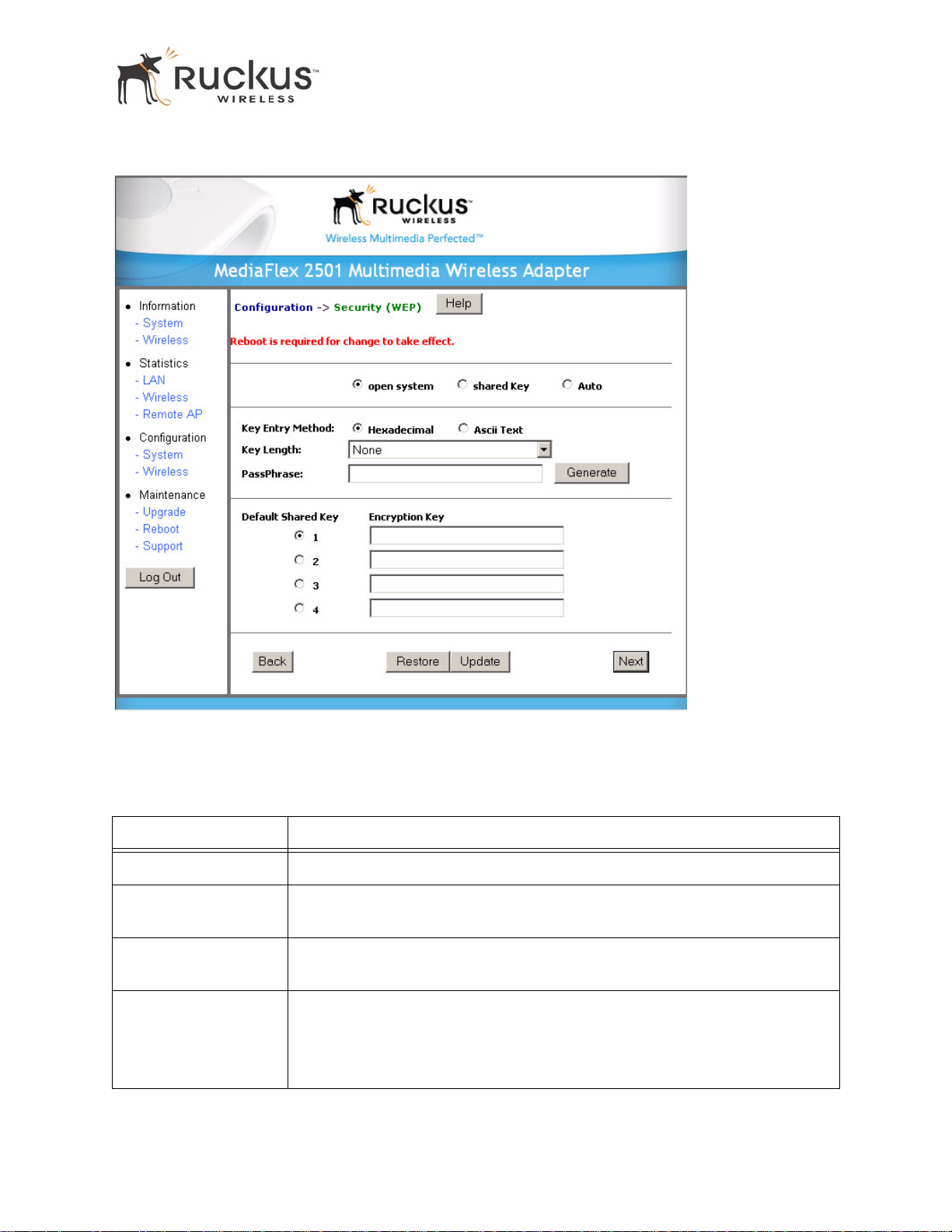
3. Click the Edit Security Settings button.TheWEP Configuration window of Figure 8 appears.
30 MF2201 MetroFlex Wireless Access Gateway User’s Guide 8000003, December 2005
Page 31
Configuring the MF 2201 Gateway
Figure 8—WEP Configuration Window
Table 11 explains the WEP Configuration parameters.
T able 11—WEP Configuration
Field Description
Open System No authentication is enforced.
Shared Key Authentication using a shared key. Shared Key authentication encrypts the SSID
and data.
Auto Automatically selects the authentication mode depending on the method used by
the remote AP.
Key Entry Method The key entry method options are:
• Hexadecimal: Accept entering encryption key with hexadecimal (0-9,
A-F).
• Ascii Text: Accept entering encryption key with ASCII characters.
8000003, December 2005 MF2201 MetroFlex Wireless Access Gateway User’s Guide 31
Page 32
Configuring the MF 2201 Gateway
T able 11—WEP Configuration (Continued)
Key Length The valid key length options are:
• None: No key.
• 40 bit WEP: Key with 10 hexadecimal digits or 5 ASCII characters.
• 128 bit WEP: Key with 26 hexadecimal digits or 13 ASCII characters.
PassPhrase This allows automatic key generation. Enter the desired passphrase and click on
the Generate button. The system will generate all four WEP keys automatically.
Default Shared Key The default share key number. There are four shared keys; select one of these
keys as the default. Make sure your MF 2201 Gateway uses the same default
shared key as the remote AP.
Encryption Keys These fields auto-fill if you use a passphrase to generate keys.
If your network doesn’t use Ruckus Wireless, Inc. APs or adapters, enter each key
manually according to the Key Entry Methods and Key Length settings. You may
specify up to four different keys and select the desired default shared key.
4. In the Configuration->Security (WEP) menu, select open system, shar ed key, or Auto. See Authentication
below for more information.
5. Select the Key Entry Method: Hexadecimal or Ascii T ext.
6. Select the Key length: 40 bit WEP or 128 bit WEP.
7. If your MF 2201 Gateway will be used with an MF2900 AP, you may use the same passphrase to generate
four unique keys. Enter a passphrase and press the Generate button. If using a remote AP from another
manufacturer, you should manually enter the four WEP keys in the same order.
8. Click the Update button to save your settings.
Authentication
WEP allows three authentication options: open system, shared key, or automatic selection of
authentication method.
Under an open system, a shared key is not required for the adapter to authenticate to a remote AP such as
the Ruckus Wireless, Inc. MF2900 AP. However, a shared key must still be used to encrypt and decrypt data
between the MF 2201 Gateway and the remote AP.
Shared key authentication adds another layer of securit y by requiring that the MF 22 01 Gateway supply a
shared key first to authenticate to the remote AP, and then supply the same shared key for encrypting and
decrypting data.
Using a Passphrase to Generate Keys
The MF 2201 Gateway supports automatic generation of four keys from a passphrase. Make sure that the
passphrase is the same as the passphrase used on the remote AP.
1. Enter a word or group of printable characters in the Passphrase box and click the Generate button. The
passphrase is case sensitive; e.g. MediaFlex is not the same as ME DIAFL EX. The four key boxes will be
automatically populated with key values.
2. Click the Update button to save your settings.
32 MF2201 MetroFlex Wireless Access Gateway User’s Guide 8000003, December 2005
Page 33
Configuring the MF 2201 Gateway
Configuring WPA PSK
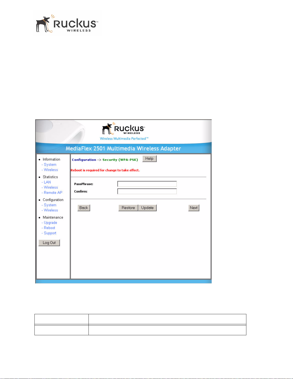
WPA PSK c onfiguration menu a llows automatic key generation based on a single passphrase. WPA PSK
provides very strong security, but may not be supported on older systems.
If you configure the MF 2201 Gateway with WPA-PSK, the other devices in the network will not connect
unless they , too are set to WPA-PSK, and are configured with the same passphrase.
1. Click the Configuration -> Wireless link in the left-hand navigation pane ( Figure 6).
2. Select WP A- PSK in the Security d rop-down menu.
3. Click the Edit Security Settings button.The WPA Configuration appears ( Fig ure 9).
Figure 9—WPA Configuration
Table 12 explains the WPA Configuration parameters
T able 12—WPA Configuration
Field Description
PassPhrase / Confirm Enter a passphrase and enter it again in the Confirm field.
8000003, December 2005 MF2201 MetroFlex Wireless Access Gateway User’s Guide 33
Page 34
Viewing System Information
4. In the Configuration ->Security (WPA-PSK) menu, enter a passphrase and enter it again in the Confirm
field.
5. Click the Update button to save your settings.
Viewing System Information
The Information Screens provide information the MF 2201 Gateway settings.
System Information
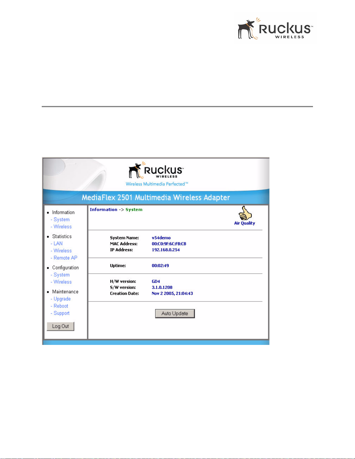
The System Information screen is the first screen to appear once you login to the MF 2201 Gateway. Figure
10 shows the System Information window.
Figure 10—System Information Window
34 MF2201 MetroFlex Wireless Access Gateway User’s Guide 8000003, December 2005
Page 35
Table 13 explains the System Information Parameters.
T able 13—System Information Parameters
Field Description
Viewing Wireless Information
System Name
MAC Address
IP Address
Uptime The system uptime since last reboot, displayed in HH:MM:SS
H/W Version The hardware revision.
S/W Version The firmware version that is currently operating.
Creation Date The date/time that the firmware was created.
The local name for the MF 2201 Gateway.
The MAC address of the MF 2201 Gateway, or the station behind the
adapter.
The IP address of the MF 2201 Gateway.
(hours, minutes, seconds).
Viewing Wireless Information
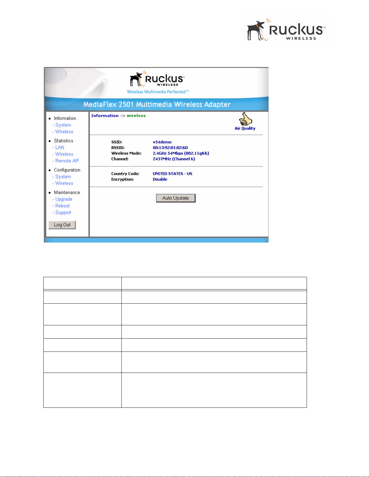
The Wireless information menu shows the current wireless configurations for the MF 2201 Gateway. To
view this window, click Information->Wireless from any window. Figure 11 shows the Wireless
Information Window.
8000003, December 2005 MF2201 MetroFlex Wireless Access Gateway User’s Guide 35
Page 36
Viewing Wireless Information
Figure 1 1—Wireless Information W indow
Table 14 shows the Wireless Information Window parameters.
T able 14—Wireless Information Window Parameters
Field Description
SSID The SSID (Service Set Identifier) is the name of the wireless network.
BSSID
Wireless Mode The wireless mode, such as 2.4 GHz 54Mbps (802.11b/g)
Channel The wireless channel number and operating frequency in MHz.
Country code
Encryption Describes the encryption type currently in use. The encryption types are
The BSSID is the MAC address of the
Gateway
The country in which the MF 2201 Gateway is operating.The country
code will automatically select the Channels available for that country.
WEP, WPA-PSK, or disabled. For more information about each type of
encryption, see T able 9— “Wireless Interface Configuration” on page
27.
associated to.
remote AP that the MF 2201
36 MF2201 MetroFlex Wireless Access Gateway User’s Guide 8000003, December 2005
Page 37
Viewing Statistics
Viewing Statistics
The Statistics Screens provide statistics for a Local Area Network (LAN) interface, the wireless interface
and wireless stations.
Viewing LAN Interface St atistics
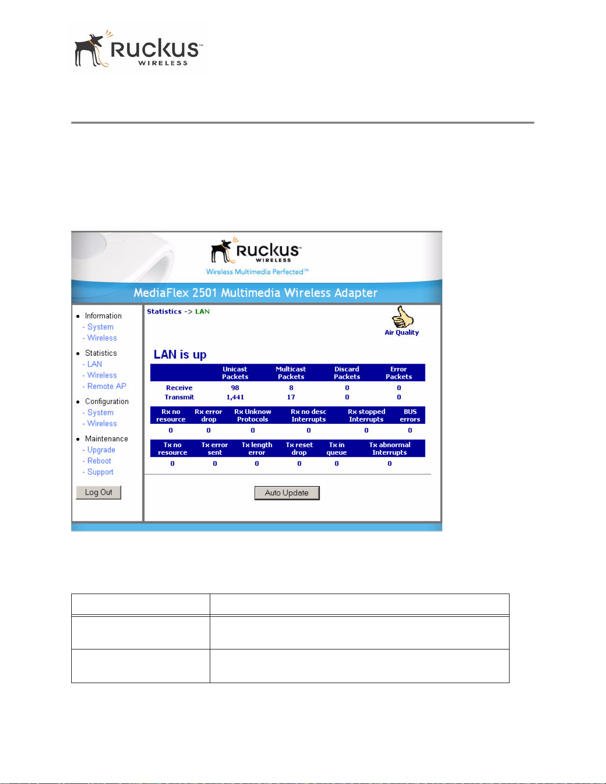
The LAN Interface statistics windows show information about packets traversing the LAN connected to the
MF 2201 Gateway. T o view the LAN interface statistics, choose Statistics->LAN from any window . Figure
12 shows the LAN Statistics Window.
Figure 12—LAN Statistics Window
Table 15 explains the LAN Statistics window parameters.
T able 15—LAN St atistics Window Parameters
Field Description
Unicast Packets The total number of unicast packets received or transmitted by the
interface.
Multicast Packets The total number of multicast packets received or transmitted by the
interface.
8000003, December 2005 MF2201 MetroFlex Wireless Access Gateway User’s Guide 37
Page 38
Viewing Statistics
T able 1 5—LAN S t atis tics W indow Para meters (Con tinued)
Field Description
Discard Packets The total number of received p ackets that were discarded by the
interface.
Error Packets The total number of error packets received or transmitted by the
interface.
Rx No Resource The number of received packets that are discarded by the interface
due to no system resources.
Rx Error Drop The number of received packets that are discarded by the interface
due to a hardware error.
Rx Unknown Protocols The number of received packets that are discarded by the interface
due to an unknown protocol.
RX No Desc Interrupts The number of received packets that are discarded by the interface
due to no descriptor interrupt.
RX Stopped Interrupts The number of received packets that are discarded by the interface
due to stopped interrupts.
BUS Error The number of received packets that are discarded by the interface
due to a BUS error.
Viewing Wireless Statistics
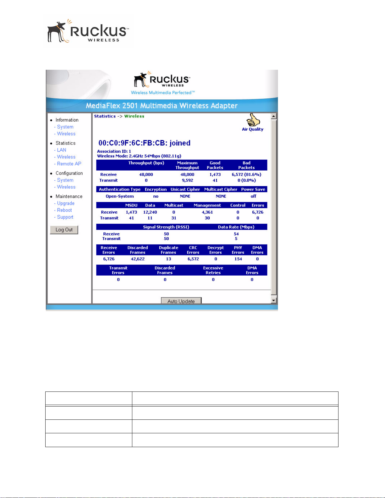
The Wireless statistics menu shows the link, traffic, and security settings for the MF 2201 Gateway. T o view
this menu, choose Statistics-Wireless from any window. The Wireless Statistics Window of Figure 13
appears. At the top of this menu, MF 2201 Gateway’s MAC address will display as either joined or
disconnected to the remote AP.
38 MF2201 MetroFlex Wireless Access Gateway User’s Guide 8000003, December 2005
Page 39
Viewing Statistics
Figure 13—Wireless Statistics
1. Click the Auto Update button to receive periodic updates to these statistics. The button will then display as
Stop Update.
2. Click the Stop Update button if you do not wish to receive periodic updates.
Table 16 shows the Wireless Statistics parameters.
T able 16—Wireless Statistics
Field Description
Throughput (bps) The average receive or transmit throughput in bits-per-second.
Maximum Throughput The high water mark receive or transmit throughput in bits-per-second.
Good Packets The total number of good packets received or transmitted by the interface.
8000003, December 2005 MF2201 MetroFlex Wireless Access Gateway User’s Guide 39
Page 40
Viewing Statistics
T able 16—Wireless Statistics (Continued)
Field Description
Bad Packets The total number of good packets received or transmitted by the interface.
Authentication Type
Encryption
The authentication type configured on the MF 2201 Gateway.
The state of encryption configured on the MF 2201 Gateway.
Unicast Cipher The type of unicast cipher used.
Multicast Cipher The type of multicast cipher used.
Power Save The state of power save mode: on or off.
MSDU The number of MSDU (Mag Service Data Unit) received or transmitted by
the interface.
Data The number of data packets received or transmitted by the interface.
Multicast The number of multicast packets received or transmitted by the interface.
Management The number of management packets received or transmitted by the
interface.
Control The number of control packets received or transmitted by the interface.
Errors The total number of error packets received or transmitted by the interface.
Signal Strength (RSSI) The RSSI value received or transmitted by the interface.
Data Rate (Mbps) The data rate in Mbps received or transmitted by the interface.
Receive Errors The total number of error packets received by the interface.
Discarded Frames The number of received or transmitted packets that were discarded by the
interface.
Duplicate Frames The number of duplicate packets received or transmitted by the interface.
CRC Errors The number of packets with CRC error received or transmitted by the
interface.
Decrypt Errors The number of packets with decryption error received or transmitted by the
interface.
PHY Errors The number of packets with PHY error received or transmitted by the
interface.
DMA Errors The number of packets with DMA error received or transmitted by the
interface.
Transmit Errors The total number of error packets transmitted by the interface.
40 MF2201 MetroFlex Wireless Access Gateway User’s Guide 8000003, December 2005
Page 41
Viewing Statistics
T able 16—Wireless Statistics (Continued)
Field Description
Discarded Frames The total number of frames discarded by the interface
Excessive Retries The total number of retries that exceed the predefined threshold.
DMA Errors The number of packets with DMA error received or transmitted by the
interface.
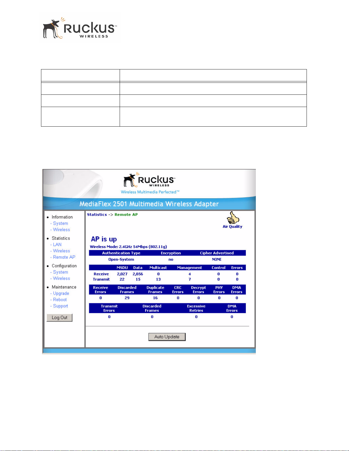
Viewing Remote AP Statistics
The Remote AP statistics menu shows statistics specific to a remote AP to which the MF 2201 Gateway is
associated. To view this menu, choose Statistics->Remote AP from any window.
Remote AP Statistics Window.
Figure 14 shows the
Figure 14—Remote AP Statistics
8000003, December 2005 MF2201 MetroFlex Wireless Access Gateway User’s Guide 41
Page 42
Viewing Statistics
describes the Remote AP Statistics parameters.
T able 17—Remote AP St atistics
Field Description
Authentication Type The authentication type used by the remote AP.
Encryption The state of encryption used by the remote AP.
Cipher Advertised The cipher advertised by the remote AP.
MSDU The number of MSDUs (Mag Service Data Unit s) received or
transmitted by the remote AP.
Data The number of data packets received or transmitted by the remote AP.
Multicast The number of multicast packets received or transmitted by the remote
AP.
Management The number of management packets received or transmitted by the
remote AP.
Control The number of control packets received or transmitted by the remote AP.
Errors The total number of error packets received or transmitted by the remote
AP.
Receive Errors The total number of error packets received or transmitted by the remote
AP.
Discarded Frames The number of received or transmitted packets that were discarded by
the remote AP.
Duplicate Frames The number of duplicate packets received or transmitted by the remote
AP.
CRC Errors The number of packets with CRC error received or transmitted by the
remote AP.
Decrypt Errors The number of packet s with decryption error received or transmitted by
the remote AP.
PHY Errors The number of packets with phy error received or transmitted by the
remote AP.
DMA Errors The number of packets with DMA errors received or transmitted by the
remote AP.
Transmit Errors The number of packets with transmit errors received or transmitted by
the remote AP.
42 MF2201 MetroFlex Wireless Access Gateway User’s Guide 8000003, December 2005
Page 43
Updating the Firmware
T able 17—Remote AP St atistics
Field Description
Discarded Frames The number of discarded frames received or transmitted by the remote
AP.
Excessive Retries The number of excessive retries received or transmitted by the remote
AP.
DMA Errors The number of packets with DMA errors received or transmitted by the
remote AP.
Updating the Firmware
This menu provides a utility for updating the MF 2201 Gateway’s firmware. A firmware update may be
necessary or desirable to add new features, important fixes or enhancements to the MF 2201 Gateway.
Contact your service provider for more information about Web sites or TFTP/FTP sites used to store
firmware images for the MF 2201 Gateway.
!
CAUTION:—If you have recently made configuration changes to the MF 2201 Gateway, make sur e to reboot
the system (see “Rebooting the System” on page 46) first so that your changes are pr eserved. Then update the
firmware.
Performing a Web Download
T o download a firmware image from a Web site and use it to update the firmware on the MF 2201 Gateway:
1. Point your browser to the Web site where the MF 2201 Gateway’s firmware is stored, and download the
firmware image to a folder on your hard drive. Note the location of the downloaded image.
2. In the Ruckus WirelessWeb Interface, click the Maintenance->Upgrade menu. The window of Figure 15
appears.
8000003, December 2005 MF2201 MetroFlex Wireless Access Gateway User’s Guide 43
Page 44

Updating the Firmware
Figure 15—Updating the Firmware
44 MF2201 MetroFlex Wireless Access Gateway User’s Guide 8000003, December 2005
Page 45
Updating the Firmware
Table 18 describes the Updating the Firmware parameters.
T able 18—Updating the Firmware
Field Description
Web Download If you have downloaded a Firmware image from a Web site and stored it
locally on your PC, you can click the Browse... button to select the image.
The path to the image will appear in the Local File Name: field.
Click the Update Firmware button located below Local File Name field.
TFTP/FTP Download Allows you to use a TFTP or FTP server to download a firmware image.
• Host Name: enter the IP address of the server.
• User Name: enter the User Name that is used to access to the
specified server. This is required only for an FTP server
• Password: enter the Password that is used to access to the
specified server. This is required only for an FTP server .
• Image Name: enter the filename of the firmware image on the TFTP
or FTP server.
Click the Update Firmware button located below Image Name field.
3. Click the Browse... button to locate and select the firmware image.
4. Click the Update Firmware button to perform the update.
5. If the firmware has updated successfully , a green check mark will appear. Click the Reboot button.
6. If the firmware did not update, a Failed: file type error message will appear .
A file type error indicates that the firmware image may be corrupt or invalid. Try downloading the
firmware image again, and repeat the above steps.
TFTP or FTP Download
T o specify a specific trivial file transfer protocol (TFTP) or File T ransfer Protocol (FTP) server from which
to download a firmware image:
1. Choose the download method by selecting either the TFTP or FTP button.
2. Enter the IP address or Hostname of the server .
3. For FTP only: Enter the User Name and Password for the server.
4. Enter the name of the firmware image.
5. Click the Update Firmware button at the bottom of the screen to perform the upgrade.
6. If the firmware has updated successfully , a green check mark will appear. Click the Reboot button.
7. If the firmware did not update, a Failed: file type error message will appear .
A file type error indicates that the firmware image may be corrupt or invalid. Check the TFTP/FTP
server address and the firmware image name. Then try downloading the firmware image again, and
repeat the above steps.
8000003, December 2005 MF2201 MetroFlex Wireless Access Gateway User’s Guide 45
Page 46
Rebooting the System
Rebooting the System
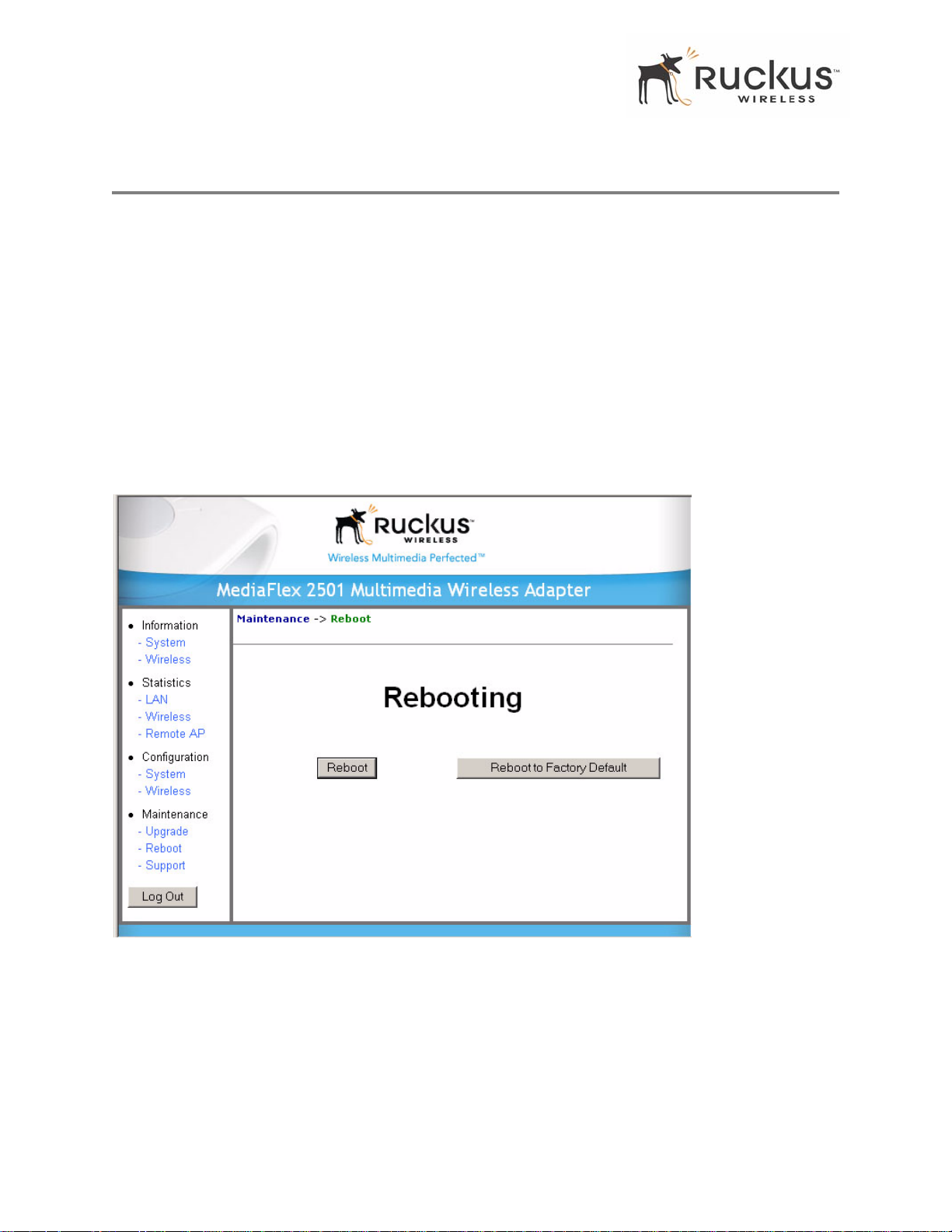
You must re boot the system if you want your configuration changes to take effect.Two types of reboot are
provided:
The Reboot button re-starts the system. All the configurations that have been saved are preserved through
the reboot. Rebooting is necessary in order to make your configuration changes permanent.
• If the system times out and you have to re-login before setting the reboot, you configuration changes will
be saved, as long as you have already clicked the Update button to save the current configuration.
• If you have powered down or logged out of the MF 2201 Gateway before clicking the Update button and
the Reboot button, your configuration changes will be lost.
The Reboot to Factory Default button restarts the system with the factory default configurations. All
previous configurations will be lost.
1. T o reboot for either type, click Maintenance->Reboot from any window . The window of Figure 16 appears.
Figure 16—Reboot Menu
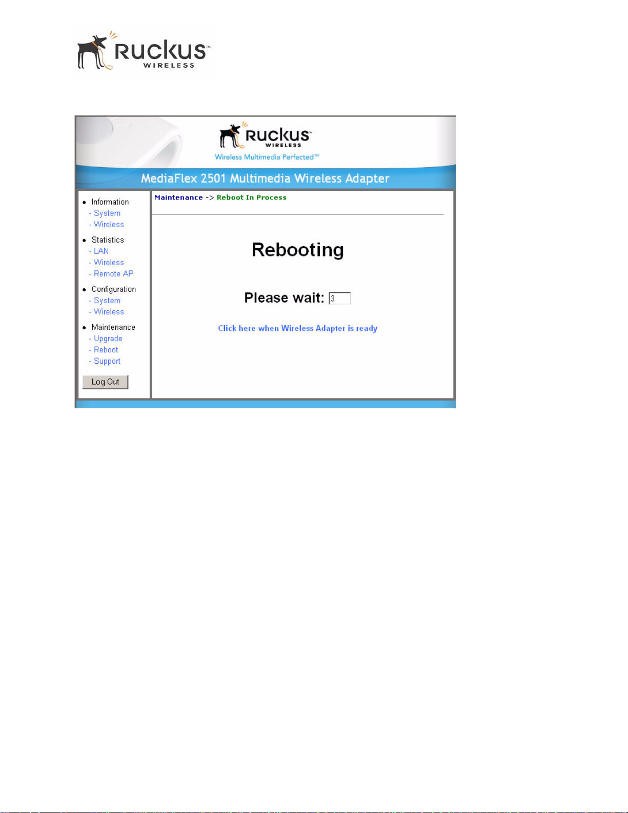
2. Click the reboot option you want. The window of Figure 17 appears.
46 MF2201 MetroFlex Wireless Access Gateway User’s Guide 8000003, December 2005
Page 47
Rebooting the System
Figure 17—Reboot in Process
During a reboot, the antenna LEDs on the top of the MF 2201 Gat eway will momentarily g o out, then light
up again.
How to tell when the Wireless Adapter is ready?
After about 18 seconds, the antenna LEDs will light up in solid green, followed by intermittent flashing. This
indicates the MF 2201 Gateway is ready. The Click here when Wireless Adapter is ready link will open
the main login page.
NOTE – If you have modified the device IP address, and then rebooted the device to factory default configuration, the
above link will not work. Instead, click the Logout button, and then point your browser to the default IP address for
the device.
8000003, December 2005 MF2201 MetroFlex Wireless Access Gateway User’s Guide 47
Page 48
Taking a System Support Snapshot
Taking a System Support Snapshot
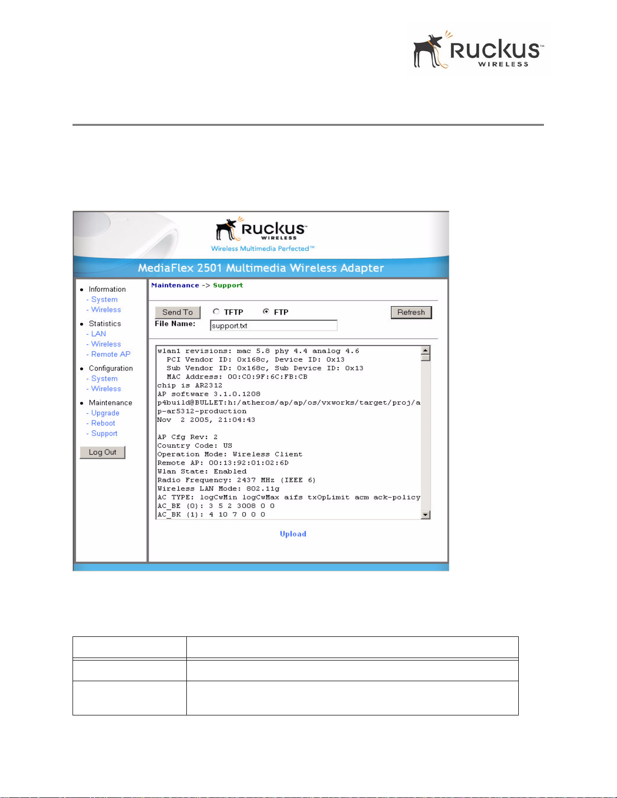
The Support menu enables you to take a system snapshot for further analysis and troubleshooting. The
system snapshot can be sent and saved to a TFTP or FTP server for analysis by a technical support engineer .
1. To view the support menu, choose Maintenance->Support from any window. The Support Menu appears (
Figure 18).
Figure 18—Support Menu
Table 19 describes the support menu parameters.
T able 19—Support Menu
Field Description
Server Type Select the server type: TFTP or FTP.
File Name S pecify the file name for the system snap shot that is to be saved on a TFTP
or FTP server.
48 MF2201 MetroFlex Wireless Access Gateway User’s Guide 8000003, December 2005
Page 49

Taking a System Support Snapshot
2. If you have not yet configured the TFTP or FTP server , click the Maintenance->Update link.
3. In the Firmware->Update menu, enter the TFTP or FTP server information. The same server is used for both
upgrading the firmware and uploading the system snapshot.
Your service provider or technical support contact should provide you with information for configuring the
TFTP or FTP server.
4. Click on the Refresh button to get the current system snapshot.
5. Click on the Send T o button to send the
support.txt file to the TFTP or FTP server. You can set the address
for the TFTP or FTP server in the Firmware Update menu.
6. Click the Upload link at the bottom of the page to upload to the specified server.
8000003, December 2005 MF2201 MetroFlex Wireless Access Gateway User’s Guide 49
Page 50

Taking a System Support Snapshot
50 MF2201 MetroFlex Wireless Access Gateway User’s Guide 8000003, December 2005
Page 51

Appendix A: Technical Specifications
Physical Characteristics
MF 2201 Gateway:
5V-1 8V 10W
External power adapter:
Power requirements
Physical size 5.72 x 4.92 x 2.9 in (145 x 125 x 74 mm.)
Weight 0.53 lbs (0.24 kg)
Unifive T echnology Co LTD, Model US300520, Input 100-240V
AC, Output 5V DC 2A, UL Listed
DVE, Model DSA-031F-12 UK 12, Input 100-240V AC, Output
12V DC 1A, TUV Certified
DVE, Model DSA-031F-12 EU 12, Input 100-240V AC, Output
12V DC 1A, TUV Certified
Antenna
Ethernet ports 1 auto MDX, auto sensing 10/100 Mbps, RJ45 port
LED display
Environmental conditions
Electromagnetic Emissions Meets requirements of FCC Part 15 Class B
Internal software-configurable antenna array with six
directional, high-gain elements and 63 unique antenna patterns
Antenna
Power
LAN
Wireless
Air Quality
Operating Temperature: 32
Operating Humidity: 15% - 95% non condensing
o
F – 104oF (0oC – 40oC)
Performance and Supported Configurations
2
Target UDP throughput
8000003, December 2005 MF2201 MetroFlex Wireless Access Gateway User’s Guide 51
15-20 Mbps sustainable throughout a typical 2500 ft
2
(300 m
) home
Page 52

Traffic Management and QoS
One MPEG-4/WMV stream, one DVD-quality MPEG-2 stream,
Video streams
Video clients Video streaming to 802.1 1b clients not supported
or one 10Mbps+ high definition stream at 50ft (18m) with
simultaneous background traffic
Traffic Management and QoS
Classes of service Voice, V ideo, Best Effort and Background
Number of hardware queues 4
Number of software queues 4
Management
Configuration and monitoring interface Ruckus Wireless Web User Interface (WebUI)
Username:
Login
Auto configuration Not available in this release
Statistics
Software update
Other Utilities System Support Snapshot
Others
Standards/Specifications
Channels
Password: <blank>
LAN, wireless and associated remote APs
Accessible via Ruckus Wireless Web Interface
Via FTP, TFTP, or Web download
Accessible via Ruckus Wireless Web Interface
802.1 1 b/g
802.11 u
802.11e,
Wi-Fi Alliance WMM
802.1x
US/Canada: 1-1 1
Europe (ETSI X30): 1-13
Japan X41: 1-13
admin
RF Power output
Certifications FCC, IC-03, CE
Wireless Security 802.1x WEP/WPA
52 MF2201 MetroFlex Wireless Access Gateway User’s Guide 8000003, December 2005
17 dBm for 802.11b
20 dBm for 802.11g
 Loading...