

Page 1
SmartCell™ Q700
Quick Setup Guide
This Quick Setup Guide provides step-by-step instructions on how
to set up your Ruckus SmartCell™ Q700 Access Point (AP). After
completing the steps described in this Guide, you will be able to
place the Q700 at your site and provide LTE wireless network
access to users.
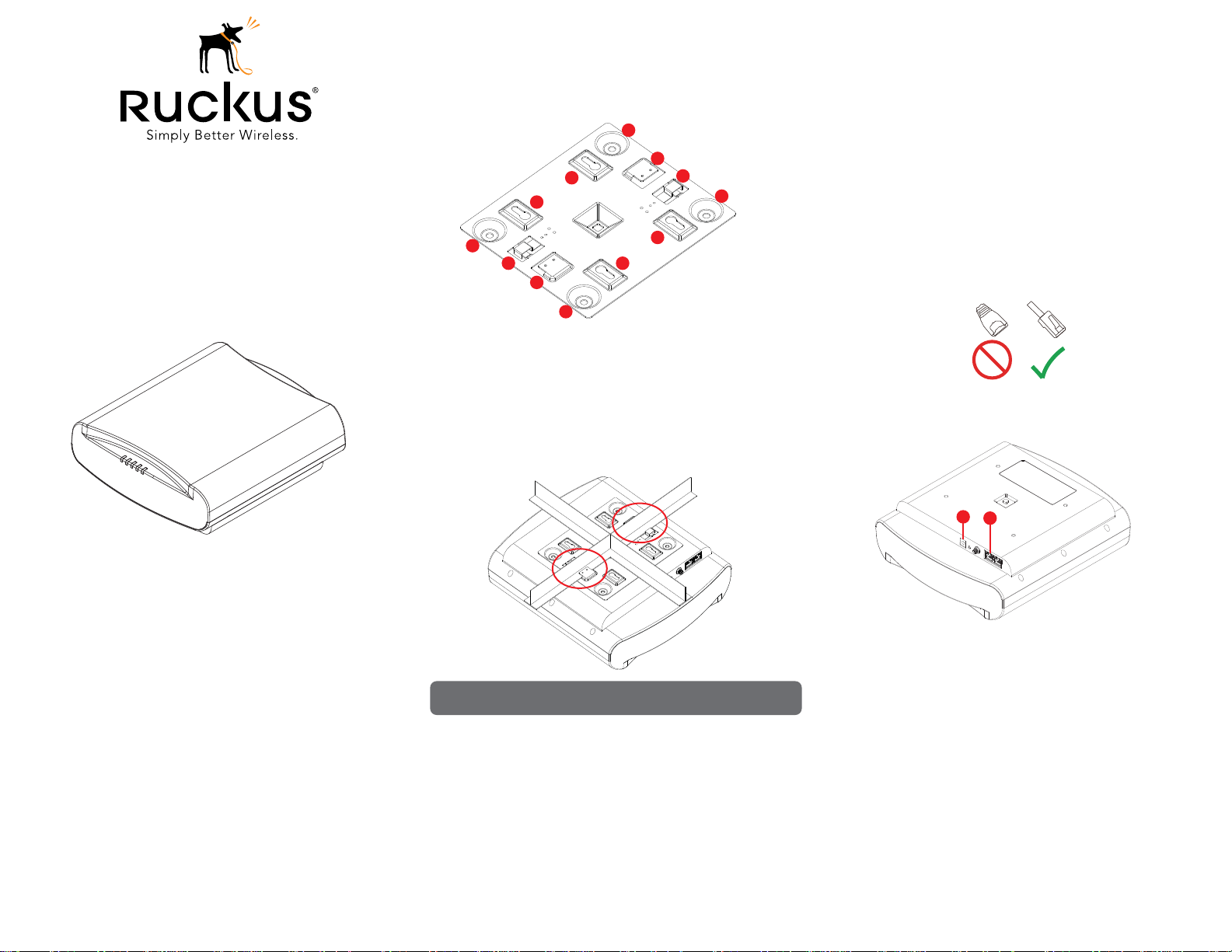
Figure 1. Ruckus SmartCell™ Q700 Access Point
Mounting on a Drop-Ceiling T-Bar
The factory-supplied mounting bracket allows you to attach the AP to
drop-ceiling T-bars.
Figure 2. AP Mounting Bracket
A
B
D
D
A
C
B
A
1) If not attached already, attach the bracket to the AP at [A] using the
included Bracket Screws.
2) Lift the AP with the bracket facing the drop-ceiling and position the
Studs [B] on the bracket slightly offset from either side of the T-bar.
3) Gently turn the AP clockwise until the Studs slip over the T-bar and
both Clasps [C] snap in place against the T-bar.
Figure 3. AP securely attached to T-bar
D
C
A
D
4) Insert the factory-supplied anchors and mounting screws into the
mounting surface, leaving approximately 6 mm (1/4”) of the screw
heads protruding for the AP bracket.
5) Place the AP and bracket onto the mounting screws so that the
screw heads enter the Keyholes [D] on the AP bracket and gently
push down.
Making the Connections
Be sure to use a Cat 5e or better Ethernet cable with non-booted
connectors (see Figure 4). If using PoE, attach one of the Ethernet
cable to an 802.3at Type 2-certified switch or PoE injector (sold
separately). Attach the other end of the Ethernet cable to the leftmost
Ethernet port [E] on the AP as shown in Figure 5. If using an AC/DC
adapter, connect it to the power port [F] in Figure 5 and to an
electrical outlet.
Figure 4. Non-booted Ethernet connector
Figure 5. Port locations
Before You Begin
Before deploying Ruckus Wireless products, please check for the
latest information and release documentation at
http://support.ruckuswireless.com/documents
Software License and Limited Warranty are available at
http://support.ruckuswireless.com/warranty
Package Contents
Check the package contents as follows:
• SmartCell Q700 Access Point
• Mounting Bracket
• 4 Bracket Screws (Phillips #2)
• 2 Wall Mounting Screws (Phillips #2)
• 2 Wall Anchors
• US AC/DC Adapter (Q700-0200 and Q700-0400 models only)
• EUR AC/DC Adapter (Q700-0300 and Q700-0700 models only)
• UK AC/DC Adapter (Q700-0300 and Q700-0700 models only)
• Product warranty statement
• This SmartCell Q700 Quick Setup Guide
Mounting Instructions
The AP can be mounted to a drop-ceiling T-bar or flat surface.
Copyright © 2015 Ruckus Wireless, Inc.
Published 17 November 2015, Part Number 800-71074-001 Rev B
Note: In order to properly support its weight, make sure that the AP is
mounted at the intersection of two rails and not along a single rail!
4) To un-mount the AP, simply press down on the two Clasps [C] and
gently turn the AP counter-clockwise until it comes off.
Mounting on a Flat Surface
The factory-supplied mounting screws and plastic wall anchors allow
you to attach the AP to a wall or ceiling.
1) Attach the bracket to the AP using the included Bracket Screws.
2) Use the Mounting Template on the last page of this Quick Setup
Guide to mark the locations for two drill holes on the mounting
surface.
3) Use a 4.75mm (3/16”) drill bit to drill holes approximately 25mm (1”)
deep into the mounting surface.
F
E
Check the LED Lights
Once connected, the AP will power on and automatically connect to
the Ruckus Cloud over the Internet to configure itself. You will see
some activity and after 2-5 minutes all lights should turn solid Green
or solid Amber. If any light is off or flashing, see the following table for
troubleshooting:
PWR Check Power, Ethernet connections and PoE switch
EMS Check Internet connection and network settings
EPC Check Internet connection and network settings
SYNC Make sure one of the APs in the network is near a window
LTE Use the Ruckus Cloud for additional guidance
For More Information
The AP is now operational and can be further managed by the Ruckus
Cloud service. For more information refer to the appropriate Ruckus
Wireless Cloud documentation or visit
http://support.ruckuswireless.com
Page 2
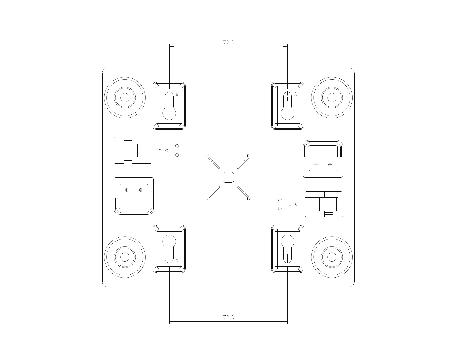
Wall Mounting Template
(All dimensions in mm)
Copyright © 2015 Ruckus Wireless, Inc.
Published 17 November 2015, Part Number 800-71074-001 Rev B
Page 3

Page 1
Federal Communications Commission Notices
This product complies with Part 15 of the FCC Rules. Operation is subject to the following two conditions: (1) this device may not cause harmful
interference, and (2) this device must accept any interference received, including interference that may cause undesired operation.
Note: This equipment has been tested and found to comply with the limits for a Class B digital device, pursuant to part 15 of the FCC Rules. These
limits are designed to provide reasonable protection against harmful interference in a residential installation. This equipment generates, uses and can
radiate radio frequency energy and, if not installed and used in accordance with the instructions, may cause harmful interference to radio
communications. However, there is no guarantee that interference will not occur in a particular installation. If this equipment does cause harmful
interference to radio or television reception, which can be determined by turning the equipment off and on, the user is encouraged to try to correct the
interference by one or more of the following measures:
—Reorient or relocate the receiving antenna.
—Increase the separation between the equipment and receiver.
—Connect the equipment into an outlet on a circuit different from that to which the receiver is connected.
—Consult the dealer or an experienced radio/TV technician for help.
FCC Caution: Changes or modifications to this equipment that have not been approved by Ruckus Wireless may void the user's authority to operate
this equipment.
This transmitter must not be co-located or operating in conjunction with any other antenna or transmitter.
Radiation Exposure Statement
This equipment complies with FCC radiation exposure limits set forth for an uncontrolled environment. This equipment should be installed and
operated with minimum distance 20cm between the radiator & your body.
Industry Canada statements
This device complies with Industry Canada’s licence-exempt RSSs. Operation is subject to the following two conditions: (1) This device may not cause
interference; and (2) This device must accept any interference, including interference that may cause undesired operation of the device.
Le présent appareil est conforme aux CNR d’Industrie Canada applicables aux appareils radio exempts de licence. L’exploitation est autorisée aux
deux conditions suivantes : 1) l’appareil ne doit pas produire de brouillage; 2) l’utilisateur de l’appareil doit accepter tout brouillage radioélectrique
subi, même si le brouillage est susceptible d’en compromettre le fonctionnement.
Radiation Exposure Statement:
This equipment complies with IC radiation exposure limits set forth for an uncontrolled environment. This equipment should be installed and operated
with minimum distance 20cm between the radiator & your body.
Déclaration d'exposition aux radiations:
Cet équipement est conforme aux limites d'exposition aux rayonnements IC établies pour un environnement non contrôlé. Cet équipement doit être
installé et utilisé avec un minimum de 20 cm de distance entre la source de rayonnement et votre corps.
Products intended to be powered by an external power supply:
Caution –This product is intended to be supplied by a Listed Direct Plug-In Power Unit marked Class 2 or LPS (sub-clause 2.5 of standard EN 60950-
1). Available Ruckus power supplies intended for product operation are identified in the product datasheet. The last two digits of the power supply
part number represent the country code. For additional applicable power supplies/options, see user instructions and product datasheet.
European Union
Česky
[Czech]
Dansk
[Danish]
Deutsch
[German]
Eesti
[Estonian]
English Hereby, Ruckus Wireless declares that this Radio LAN is in compliance with the essential requirements and other
Español
[Spanish]
Ελληνική
[Greek]
Français
[French]
Italiano
[Italian]
Ruckus Wireless tímto prohlašuje, že tento Radio LAN je ve shodě se základními požadavky a dalšími příslušnými
ustanoveními směrnice 1999/5/ES.
Undertegnede Ruckus Wireless erklærer herved, at følgende udstyr Radio LAN overholder de væsentlige krav og øvrige
relevante krav i direktiv 1999/5/EF.
Hiermit erklärt Ruckus Wireless, dass sich das Gerät Radio LAN in Übereinstimmung mit den grundlegenden
Anforderungen und den übrigen einschlägigen Bestimmungen der Richtlinie 1999/5/EG befindet.
Käesolevaga kinnitab Ruckus Wireless seadme Radio LAN vastavust direktiivi 1999/5/EÜ põhinõuetele ja nimetatud
direktiivist tulenevatele teistele asjakohastele sätetele.
relevant provisions of Directive 1999/5/EC.
Por medio de la presente Ruckus Wireless declara que el Radio LAN cumple con los requisitos esenciales y cualesquiera
otras disposiciones aplicables o exigibles de la Directiva 1999/5/CE.
ΜΕ ΤΗΝ ΠΑΡΟΥΣΑ Ruckus Wireless ∆ΗΛΩΝΕΙ ΟΤΙ Radio LAN ΣΥΜΜΟΡΦΩΝΕΤΑΙ ΠΡΟΣ ΤΙΣ ΟΥΣΙΩ∆ΕΙΣ
ΑΠΑΙΤΗΣΕΙΣ ΚΑΙ ΤΙΣ ΛΟΙΠΕΣ ΣΧΕΤΙΚΕΣ ∆ΙΑΤΑΞΕΙΣ ΤΗΣ Ο∆ΗΓΙΑΣ 1999/5/ΕΚ.
Par la présente Ruckus Wireless déclare que l'appareil Radio LAN est conforme aux exigences essentielles et aux autres
dispositions pertinentes de la directive 1999/5/CE.
Con la presente Ruckus Wireless dichiara che questo Radio LAN è conforme ai requisiti essenziali ed alle altre
disposizioni pertinenti stabilite dalla direttiva 1999/5/CE.
Page 4

Page 2
Latviski
[Latvian]
Lietuvių
[Lithuanian]
Nederlands
[Dutch]
Malti
[Maltese]
Magyar
[Hungarian]
Polski
[Polish]
Português
[Portuguese]
Slovensko
[Slovenian]
Slovensky
[Slovak]
Suomi
[Finnish]
Svenska
[Swedish]
Íslenska
[Icelandic]
Norsk
[Norwegian]
Ar šo Ruckus Wireless deklarē, ka Radio LAN atbilst Direktīvas 1999/5/EK būtiskajām prasībām un citiem ar to
saistītajiem noteikumiem.
Šiuo Ruckus Wireless deklaruoja, kad šis Radio LAN atitinka esminius reikalavimus ir kitas 1999/5/EB Direktyvos
nuostatas.
Hierbij verklaart Ruckus Wireless dat het toestel Radio LAN in overeenstemming is met de essentiële eisen en de andere
relevante bepalingen van richtlijn 1999/5/EG.
Hawnhekk, Ruckus Wireless, jiddikjara li dan Radio LAN jikkonforma mal-ħtiġijiet essenzjali u ma provvedimenti oħrajn
relevanti li hemm fid-Dirrettiva 1999/5/EC.
Alulírott, Ruckus Wireless nyilatkozom, hogy a Radio LAN megfelel a vonatkozó alapvetõ követelményeknek és az
1999/5/EC irányelv egyéb elõírásainak.
Niniejszym Ruckus Wireless oświadcza, że Radio LAN jest zgodny z zasadniczymi wymogami oraz pozostałymi
stosownymi postanowieniami Dyrektywy 1999/5/EC.
Ruckus Wireless declara que este Radio LAN está conforme com os requisitos essenciais e outras disposições da
Directiva 1999/5/CE.
Ruckus Wireless izjavlja, da je ta Radio LAN v skladu z bistvenimi zahtevami in ostalimi relevantnimi določili direktive
1999/5/ES.
Ruckus Wireless týmto vyhlasuje, že Radio LAN spĺňa základné požiadavky a všetky príslušné ustanovenia Smernice
1999/5/ES.
Ruckus Wireless vakuuttaa täten että Radio LAN tyyppinen laite on direktiivin 1999/5/EY oleellisten vaatimusten ja sitä
koskevien direktiivin muiden ehtojen mukainen.
Härmed intygar Ruckus Wireless att denna Radio LAN står I överensstämmelse med de väsentliga egenskapskrav och
övriga relevanta bestämmelser som framgår av direktiv 1999/5/EG.
Hér með lýsir Ruckus Wireless yfir því að Radio LAN er í samræmi við grunnkröfur og aðrar kröfur, sem gerðar eru í
tilskipun 1999/5/EC.
Ruckus Wireless erklærer herved at utstyret Radio LAN er i samsvar med de grunnleggende krav og øvrige relevante
krav i direktiv 1999/5/EF.
800-71054-001-A
 Loading...